1
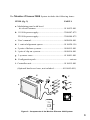
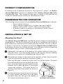
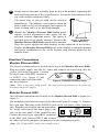
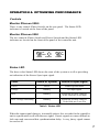
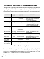
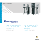
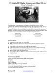
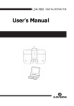
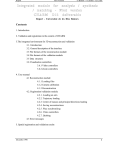
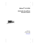
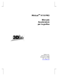
MONITOR 2000 Series 2 User’s Manual StereoGraphics Corporation 2171 East Francisco Blvd. • San Rafael, CA 94901 S T E R E O G R A P H I C S phone: USA & Canada (800) 783-2660 all other areas (415) 459-4500 fax (415) 459-3020 e-mail: [email protected] web site: www.stereographics.com Table of Contents INTRODUCTION TO THE MONITOR ZSCREEN® 2000 SERIES 1 DESCRIPTION OF CONTENTS 2 PRODUCT CONFIGURATION 4 PREREQUISITES FOR OPERATION 4 INSTALLATION & SET UP 4 OPERATION & OPTIMIZING PERFORMANCE 7 MAINTENANCE 9 TECHNICAL SUPPORT & TROUBLESHOOTING 10 SPECIFICATIONS 11 ACCESSORIES & REPLACEMENT PARTS 11 STEREOGRAPHICS’ FAMILY OF PRODUCTS 11 WARRANTY INFORMATION 13 FCC COMPLIANCE 13 WARNING: DO NOT use an abrasive material to clean the Monitor ZScreen 2000 Series panel or eyewear. They can be easily scratched. See “MAINTENANCE” section for correct cleaning and care procedure. INTRODUCTION TO THE MONITOR ZSCREEN® 2000 SERIES Thank you for purchasing StereoGraphics’ Monitor ZScreen 2000/2000i. The Monitor ZScreen 2000/2000i is a stereoscopic viewing system comprising a stereoscopic viewing panel, which is affixed over the monitor screen, and polarized eyewear. It delivers high-performance Stereo3D® visualization capabilities. Designed for engineers, scientists and medical professionals who need to view complex 3D computer graphics models, the Monitor ZScreen 2000 Series provides the most realistic representation possible of visual information. Highly regarded for GIS/Mapping applications, especially for dual display systems, the Monitor ZScreen 2000 Series produces the ideal solution for medical imaging, small group design review, presentations and simulations. The Monitor ZScreen 2000/2000i allows users to reduce errors and increase productivity by providing high-resolution Stereo3D visualization for professional applications. What is Stereo3D? Stereo3D is the use of computer technology to recreate the way we naturally see depth with two eyes — stereoscopically. Stereo3D delivers the most realistic visual representation possible of complex digital models, giving engineers, scientists and medical professionals the best possible understanding of three-dimensional information, and yielding heightened visualization not available using a typical 3D view. How It Works Stereoscopic displays are possible whenever a means is provided for creating and presenting different perspective views to the left and right eyes. Each view is generated from an appropriately shifted viewing location. There are several methods of displaying these varying views, one of the most popular being the field sequential method. In this case a source (typically a computer) shows first one eye’s view on its display screen (typically a CRT monitor), then shows the other eye’s view. The image source generates a signal as a means of identifying the on-screen image as a left or right image. Once the left and right images are presented, a selection device is required. The selection device in this case is the combination of an electrically controlled polarization modulating panel and passive polarizing eyewear. A controller unit activates the panel in synchrony with the sync signal provided. The Monitor ZScreen 2000 Series panel is made of conventional liquid crystal and is electronically controlled to change the characteristics of polarized light from passing through it. Polarizing filters in the eyewear allow only the correct perspective images to reach each eye. 1 DESCRIPTION OF CONTENTS The Monitor ZScreen 2000i System includes the following items: ITEM (fig. 1) PART # a. Modulating panel with bezel & velcro fasteners ................................................ 0110030-001 b. 110 Volt power supply............................................. 2300007-072 220 Volt power supply............................................. 2300008-072 c. User’s manual.......................................................... 0420054-001 d. 1 vertical alignment spacer...................................... 0110028-156 e. 2 pairs of deluxe eyewear........................................ 0010015-001 f. 1 pair of clip-on eyewear......................................... 0010016-001 g. 3 eyewear cases....................................................... 4110001-001 h. Configuration pack............................................................various (Optional hard travel case, not included.................4110005-001) d. a. f. b. e. g. h. c. Figure 1. Components of the Monitor 2000i System 2 The Monitor ZScreen 2000 System includes the following items: ITEM (fig. 2) PART # a. Modulating panel with bezel & velcro fasteners ................................................ 0110032-001 b. 110 Volt power supply............................................. 2300007-072 220 Volt power supply............................................. 2300008-072 c. User’s manual.......................................................... 0420054-001 d. 1 vertical alignment spacer......................................0110028-156 e. 2 pairs of deluxe eyewear........................................ 0010015-001 f. 1 pair of clip-on eyewear..........................................0010016-001 g. 3 eyewear cases....................................................... 4110001-001 h. Configuration pack............................................................various i. Controller unit.......................................................... 0110015-001 (Optional hard travel case, not included.................4110005-001) d. a. f. b. e. g. i. h. c. Figure 2. Components of the Monitor ZScreen 2000 System 3 PRODUCT CONFIGURATION In addition to the components detailed in “Description of Contents,” all Monitor ZScreen 2000 Series systems are supplied with a Monitor ZScreen 2000 Series Configuration Pack. The contents of each pack is specific to the platform for which it is intended and are detailed in “Installation & Setup.” PREREQUISITES FOR OPERATION The following items are required for the Monitor ZScreen 2000 Series to operate: • Stereo-enabled software • Stereo-enabled computer (e.g., systems with stereo-enabled graphics card) or EPC-2 for PC’s that are not stereo-ready • A monitor capable of running at a minimum of 100Hz vertical refresh rate recommended INSTALLATION & SET UP Mounting the Panel The Monitor ZScreen 2000 Series modulating panel is shipped assembled into a mounting bezel. The bezel is designed to sit on top of your monitor and is held in place with two pre-installed pieces of hook-and-loop fastener (Velcro®) as shown in Figure 2. The bezel is designed to position the Monitor ZScreen 2000 Series in the proper location for virtually all users. For additional vertical adjustment, StereoGraphics has provided a vertical alignment spacer. 1 Thoroughly clean the top of the monitor. The surface needs to be clean, dry, and free of oils. Use clean wiping material with isopropyl alcohol (rubbing alcohol) to free surface of contaminates and allow to dry. 2 Determine the location of the panel on the monitor. Gently place the panel centered in front of the monitor as shown in Figure 3. Make sure the panel is sitting flat on the front bezel of the monitor. The panel has standouts built into the surround which will leave an optimal gap between the panel and the monitor screen when the panel is positioned against the monitor. The panel should lie parallel to the front of the monitor, as shown in Figure 4. 3 Peel the release liner from the back of each piece of velcro fastener and gently lower the panel assembly down onto the top of the monitor in the location determined in Step 2. 4 Figure 3. Attaching Hook-and-Loop Fasteners 4 Gently remove the panel assembly from the top of the monitor, separating the hook and loop portions of the velcro fastener. Secure the loop fastener on the top of the monitor and press firmly. The panel may be placed back on the monitor immediately. The adhesive used requires about an hour to achieve 80% of full strength, and requires 30 hours to reach 100% of its full bond strength. 5 Should the Monitor ZScreen 2000 Series panel require vertical alignment at this point, use the provided vertical alignment spacer. The spacer is provided with velcro already attached. Remove the Figure 4. Modulator Panel Mounting Monitor ZScreen 2000 Series unit from the monitor. Place the spacer against the hook fastener on the underside of the bracket. Replace the Monitor ZScreen 2000 panel on the display, securing the bracket and spacer combination to the velcro fastener strip already applied to the monitor bezel. Electrical Connections Monitor ZScreen 2000i The electrical connections are located on the top of the Monitor ZScreen 2000i. Plug the power supply into the AC outlet and connect the barrel plug into the ‘power’ jack on the rear panel. Connect POWER CE the stereo sync cable BNC connector Other to INPUT (see figure 5) and PHASE INPUT 18VAC 2VA connect the other end of the cable Figure 5. Controller Unit Rear Panel into the computer. (Note: There is no power on/off switch. The unit is best left powered on. To power off, disconnect the power supply.) Monitor Zscreen 2000 Three electrical connections must be made for the Monitor ZScreen 2000 to operate (see Figure 6). The modulator panel must be connected as shown in Figure 2 (on page 3). Connect the 6-pin mini-DIN plug to the SCREEN jack on the rear panel of the controller unit. Plug the power supply into an appropriate SCREEN POWER AC outlet, and connect the barrel plug to the jack on the rear panel of the controller unit. INPUT 18VAC 2VA Connect the stereo sync signal BNC connector to the BNC jack labeled INPUT and connect Figure 6. Controller Unit Rear Panel the other end to the computer (as instructed in the configuration pack). (Note: The 3.5 mm INPUT jack is not normally used.) 5 Configuration Pack and Interface Cable The Monitor ZScreen 2000 Series must be connected to a computer or other signal source that is creating an alternating field sequential stereoscopic image. This signal source needs to send a stereo sync signal to the Monitor ZScreen 2000 Series controller electronics via the BNC connector. Below are the stereo Configuration Pack requirements for most computers supported by StereoGraphics Monitor ZScreen 2000 Series. If you are a current CrystalEyes user, a new cable may not be required for the Monitor ZScreen 2000 Series. In most cases a BNC adapter will be required. For complete information on the adapter and/or cable requirements, please visit StereoGraphics’ web site at www.stereographics.com. Configuration Pack Name ALPHA Configuration Pack Configurations Covered All stereo-ready Compaq ALPHA workstations (formerly DEC) SGI Configuration Pack All stereo-ready SGI UNIX Computers Sun Configuration Pack All stereo-ready Sun Microsystems computers IBM Configuration Pack All stereo-ready IBM computers Intergraph Configuration Pack All Intergraph computers equipped with RealiZm, RealiZm II and Intense3Dgraphics cards * HP Visualize 48 Configuration Pack All stereo-ready HP VISUALIZE 48 graphics cards HP Visualize FX Configuration Pack Stereo NT Configuration Pack BNC Configuration Pack All HP VISUALIZE FX graphics cards All PC graphics cards equipped with a VESA-specified 3-pin mini-DIN connector For all platforms supplying sync through a BNC connection Table 1. Configuration Pack Requirements * Intense 3D cards have either a 5-pin or 3-pin mini-DIN stereo connector. The Stereo NT configuration pack is required for the latest cards which have the 3-pin connector (Wildcat 4105 and 4110 and newer). 6 OPERATION & OPTIMIZING PERFORMANCE Controls Monitor ZScreen 2000i There is one control (Phase Switch) on the rear panel. The Status LED indicator is located on the front of the panel. Monitor ZScreen 2000 The two controls (Phase Switch and Power Switch) and the Status LED indicator are located on the front of the panel of the controller unit. STEREOGRAPHICS CE Other PHASE STATUS Monitor ZScreen On Off POWER Figure 7. Controller Unit Front Panel Status LED The three-color Status LED shows the state of the system as well as providing an indication of the Stereo Sync input signal. Color Status of System Status of Input Signal Green Active Within specifications Orange Standby No input signal Red Standby Signal has recently changed or the field rate is too high Red / Orange alternating Standby Signal has recently changed or the field rate is too low Table 2. Status LED When the input signal changes, it normally takes a few seconds for the controller unit to synchronize itself with the new signal. Erratic signals are more difficult to lock onto and can extend this synchronization delay. A very jittery signal cannot be used at all. 7 Startup When the controller is powered ON, the panel will ‘cycle’ for about 7 seconds – this ensures that all the modulator segments are fully activated and 100% efficiency is achieved. This ‘cycling’ is noticeable as a ‘flashing’ effect, only if the user is wearing the polarized glasses when the unit’s power is turned on. Activation The modulator panel is always active whenever the unit is switched on – regardless of whether a stereo sync signal is being received. It will cycle freely (free-running) until a stereo sync signal is received, at which point it will instantly re-sync. The free-running will only be noticeable if the user is wearing the polarized eyewear. Phasing Phasing refers to the relationship between the perspective of the image and the eye seeing the image. That is, does the left eye see the image destined for the left eye, or does it see the image destined for the right eye. When using computers and software that are compatible with StereoGraphics’ CrystalEyes, phasing control is simply achieved. Set the PHASE switch to “CE”. This will set up the system for proper phasing for all CrystalEyes compatible images, and all other images that follow the StereoGraphics and VESA standards. When using other sources, it may be necessary to change the phasing. Set the phasing switch to “OTHER” to reverse the phase from normal. Figure 8. Zero Parallax Figure 9. Positive Parallax If you are unsure of the proper switch setting, a bit of background in stereoscopy can help. In stereoscopic imaging, the left and right eyes generally see the same objects, but at slightly different positions (horizontally). This difference in position is called parallax. When an object is in the same position in both the left and right eyes, there is no difference in position and hence zero parallax (see Figure 8). The objects 8 Figure 10. Negative Parallax appear correct whether or not they are viewed while wearing the polarizing eyewear through the Monitor ZScreen 2000/2000i. These objects appear to be located at the surface of the monitor. When an object is farther to the right in the right eye and farther to the left in the left eye it is called positive parallax (see Figure 9). The objects appear doubled unless they are viewed while wearing the polarizing eyewear through the Monitor ZScreen 2000/2000i. These objects appear to be located behind the surface of the monitor. When an object is farther to the left in the right eye and farther to the right in the left eye it is called negative parallax (see Figure 10). The objects also appear doubled unless they are viewed while wearing the polarizing eyewear through the Monitor ZScreen 2000/2000i. These objects appear to be located in front of the surface of the monitor. Thus, you should be able to verify the phasing of the Monitor ZScreen 2000/2000i by looking at the parallax of an object. Without wearing the polarizing eyewear, choose an object that has a large value of parallax that should be far in the distance. Then put on the eyewear and look at the image first only through the left eye and then only through the right eye. If a distant object is farther to the right in the right eye, the parallax is positive and the phasing switch is in the correct position. MAINTENANCE The Monitor ZScreen 2000/2000i Series requires no maintenance other than simple cleaning. If a problem occurs with the unit, consult the Troubleshooting portion of this manual. Clean the Monitor ZScreen 2000 Series modulator panel with Windex or any other domestic glass cleaner, and a chamois, soft cloth or tissue. NOTE: DO NOT use an abrasive material to clean the Monitor ZScreen 2000 Series, as the panel can be easily scratched. Use spray cleaner sparingly. 9 TECHNICAL SUPPORT & TROUBLESHOOTING The LED on the front panel of the controller unit is a very important troubleshooting tool. The state of this indicator can provide the user with valuable information regarding the operation of the system. When there is a problem with the system, check the status of this indicator and refer to the following troubleshooting chart: SYMPTOM LED STATE POSSIBLE PROBLEM SOLUTION No stereo image. Off No power to controller unit. • Plug the AC power supply into the power outlet and the barrel connector into the ‘power’ jack. • Turn on the POWER switch.* No stereo image. Orange No stereo sync signal. • Confirm the image is indeed a stereo image and that the graphics card is configured for stereo output. • Check that the stereo sync cable is correctly connected at both ends. No stereo image. Red Sync signal is too fast. Decrease the vertical refresh rate to less than 200 Hz. No stereo image. Red Sync input is connected to Vertical Sync. Connect Sync input to a Stereo Sync source. Red / Orange Sync signal is too slow. alternating Increase the vertical refresh rate to more than 40 Hz. No stereo image. No stereo image. Green Panel is not energized. Check that the 6-pin connector is correctly plugged into the controller unit.* Partial stereo image. Green Panel is only partially energized. Secure the 6-pin panel connector into the rear of the controller unit.* Stereo image on top half of monitor only. Green Sync input is connected to Vertical Sync. Connect Sync input to a Stereo Sync source. Stereo image appears “inside out” or reversed. Green Sync signal is out of phase with image. Toggle the phase switch. Table 3: Troubleshooting Chart For additional technical support & troubleshooting, please visit StereoGraphics’ web site at www.stereographics.com or contact StereoGraphics’ Technical Support directly via e-mail at [email protected] or by calling (800) 783-2660 (within USA & Canada) or (415) 459-4500 (all other areas). *Applies to the Monitor ZScreen 2000 only. 10 SPECIFICATIONS • Light Transmission • Shutter Type • • • • Minimum field rate Maximum field rate Viewing area External frame dimensions: 2000i 2000 • Power supply 29% Surface Mode Scanning Byatt Modulator 20 Hz per frame, 40 Hz field rate 100 Hz per frame, 200 Hz field rate 15-3/4” x 12” 20-1/8”w x 18”h x 4 1/4”d 20-1/8”w x 17-1/8”h x 4 1/4”d 18 Volts AC, 2 VA, external Specifications are subject to change without notice. ACCESSORIES & REPLACEMENT PARTS For some applications, stereoscopic images are presented in interlaced format. In this situation additional controller hardware may be necessary for the Monitor ZScreen 2000 only. Users who frequently travel with the Monitor ZScreen 2000 Series may also order a hard travel case for the product. These accessories and replacement parts can be purchased through authorized StereoGraphics resellers listed on our web site (www.StereoGraphics.com). Please refer to part numbers listed in Figure 1 on page 3. For more information contact StereoGraphics via e-mail at [email protected] or by telephone at (800) 783-2660 (within USA & Canada) or (415) 459-4500 (all other areas). STEREOGRAPHICS’ FAMILY OF PRODUCTS StereoGraphics is the world’s leading supplier of Stereo3D visualization products. These products are utilized for the realistic recording and display of Stereo3D images. With more than 75,000 users, StereoGraphics’ products have been in use for nearly a decade in key design and engineering centers such as General Motors, Ford, Boeing and NASA. Engineers and scientists have used StereoGraphics’ products to design next-generation automobiles and aircraft, develop life-saving drugs, interpret images gathered from deep space, and even guide the Pathfinder mission on Mars. 11 In addition to the Monitor ZScreen 2000 Series, StereoGraphics offers the following products: CrystalEyes® CrystalEyes is a lightweight, wireless set of liquid crystal shutter eyewear for Stereo3D imaging in engineering and scientific applications. The product delivers high definition, stereoscopic 3D images on all major UNIX platforms and Windows NT workstations in conjunction with compatible software and standard workstation displays. CrystalEyes is activated by an infrared emitter that connects to the user’s workstation. CrystalEyes® Wired CrystalEyes Wired is an entry-level stereoscopic eyewear system for mechanical design, molecular modeling, computational chemistry and architectural CAD professionals working with complex 3D images. It was developed to take advantage of the new generation of OpenGL graphics cards using the VESA standard 3-pin mini-DIN connector. The product delivers high-definition, Stereo3D viewing capability on Windows NT workstations in conjunction with compatible software and standard workstation displays. The user simply plugs the CrystalEyes Wired 3-pin connector into a compatible graphics card and the eyewear is automatically activated whenever a Stereo3D application is running. Projection ZScreen® Projection ZScreen works with CRT projectors to allow audiences to view stereoscopic content using polarized glasses. The Projection ZScreen is ideal in environments where concepts, facts and results must be communicated clearly, precisely and with impact to large audiences. CrystalEyes® Video System The CrystalEyes Video System permits high-resolution, flicker-free, full-color stereo images to be simultaneously viewed and transmitted, or recorded and played back with a single VCR. The CrystalEyes Video System is a completely self-contained, affordable system that works with virtually all video equipment worldwide. The System includes a view/record unit, a playback unit and a stereo video camera. CrystalEyes® VR CrystalEyes VR is hardware that allows the user to interact with a virtual world through a stereo “window.” CrystalEyes VR changes the perspective of the image without having to touch a mouse, joystick or keyboard, allowing the user to literally “look around” objects displayed on the monitor. As the user’s head moves from side to side, closer to or further away from the monitor, the image on the display changes its perspective, giving the convincing illusion the image is a real object. The user’s hands are left free to manipulate the data, not the viewpoint. For additional product, sales or reseller information on the Monitor ZScreen and other products from StereoGraphics, call (800) 783-2660 (within USA & Canada) or (415) 459-4500 (all other areas) or visit the company’s web site at www.stereographics.com or send an e-mail to [email protected]. 12 Warranty Information To ensure full warranty coverage, please fill out the enclosed Warranty Registration Card or visit our website to register or view warranty online at www.StereoGraphics.com. FCC Compliance This equipment generates and uses radio frequency energy, and if not installed and used in strict accordance with the manufacturer’s instructions, may cause interference to radio and television reception. The equipment has been tested and found to comply within the limits for a Class B computing device in accordance with the specifications in Subpart B of Section 15 of the FCC rules, which are designed to provide reasonable protection against such interference in a residential installation. However, there is no guarantee that interference to radio or television reception will not occur, which can be determined by turning the equipment on and off. The user is encouraged to try to correct the interference by one or more of the following measures: • • • • Re-orient the receiving antenna. Relocate the equipment with respect to the receiver. Move the equipment away from the receiver. Plug the equipment into a different outlet so that the equipment and receiver are on different branch circuits. If necessary, the user should consult the dealer or an experienced radio /television technician for additional suggestions. The user may find the following booklet prepared by the Federal Communications Commission helpful: “How to Identify and Resolve Radio-TV Interference Problems” This booklet is available from: US Government Printing Office Washington, D.C. 20402 (Stock No. 004-000-0345-4) To meet FCC requirements, shielded cables are required to connect the equipment to a personal computer or other Class B certified device. Any changes or modifications not expressly approved by the party responsible for compliance could void the authority to operate the equipment. StereoGraphics, CrystalEyes and ZScreen are registered trademarks and Stereo3D is a trademark of StereoGraphics Corporation. All other product names, trademarks, and/or company names are used solely for identification and belong to their respective holders. 13 S T E R E O G R A P H I C S StereoGraphics Corporation 2171 East Francisco Blvd. • San Rafael, CA 94901 phone: USA & Canada (800) 783-2660 all other areas (415) 459-4500 fax (415) 459-3020 e-mail: [email protected] web site: www.stereographics.com 0420054-001A