1
United States Patent [191
[11]
[45]
Ogawa et a1.
[54] TERMINAL SWITCHING CONTROL
Patent Number:
Date of Patent:
4,868,865
Sep. 19, 1989
FOREIGN PATENT DOCUMENTS
APPARATUS
[75] Inventors: Fukushige Ogawa; Chiaki Motegi;
Chikara Hosokawa, all of Tokyo,
0242449 10/1986
2183427 6/1987
Japan ................................. .. 379/100
United Kingdom .............. .. 379/105
[73] Assignee: Kabushiki Kaisha Toshiba, Kawasaki,
Japan
Primary Examiner-Jin F. Ng
Assistant Examiner—Mehdi Haghani
Attorney, Agent, or Firm-Cushman, Darby & Cushman
[57]
ABSTRACT
[21] Appl. No.: 160,844
A terminal switching control apparatus includes a con
troller. The controller responds to one of a record stop
[22] Filed:
(RS) signal, a communication signal from a telephone,
and a facsimile communication end (FCE) signal from a
Japan
[30]
Feb. 26, 1988
facsimile to monitor a call detect CED signal from a call
detector. The controller determines whether the mode
Foreign Application Priority Data
Feb. 21, 1987 [JP]
Mar. 13, 1987 [JP]
set by a mode setting section is a ?rst mode or a second
Japan ................................ .. 62-44518
Japan ................................ .. 62-58121
mode, in response to the CED signal from the call de
tector. In the ?rst mode, the controller responds to a
Int. Cl.4 .................... .. H04M 11/00; H04M 1/65
U.S. Cl. ................................. .. 379/ 100; 379/80
Field of Search ........................ .. 379/ 100, 80, 105
time period and outputs a switch control (SC) signal to
CNG detect signal from a CNG detector within a ?rst
[51]
[52]
[58]
[56]
References Cited
U.S. PATENT DOCUMENTS
4,564,724
l/ 1986
Nakayama et a1. ............... .. 379/100
4,639,553
l/ 1987
Kiguchi ..... ..
4,653,086
3/1987
Laube .... ..
4,677,660
6/1987 Yoshida
4,692,817
9/1987
. 379/ 100
. 379/100
a switch so as to couple a communication line to the
facsimile, and then responds to the communication sig
nal upon elapse of the ?rst time period and outputs the
SC signal to the switch so as to couple the communica
tion line to the telephone. In the second mode, the con
troller outputs a record start control (RSC) signal to a
recording section and outputs the RS signal to the re
cording section upon elapse of a second time period.
. 379/100
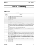
16 Claims, 7 Drawing Sheets
Theis ................................... .. 379/ 80
FACS IM 1 LE
CONTROLLER
6
-TCU i
TCROLNER
CALL
DETECTOR
SETTING
SECTION
1
US. Patent
Sep. 19,1989
Sheet 2 Of 7
4,868,865
D
30
YES
MODE
SETTING
?
3b
YES
NO
PERFORM CALLING
OPERATION
3C
INCOMING '?
‘
YE 3
6
FORM
DC LOOP
3
3n
3d
AUTO
ANSWERING
MODE ?
YES
No
O
TRANsMIT
3f
MESSAGE
3?!
Is TIME
‘NO
g
PERFORM MODE
SETTI NG OPERATION
NO
OUTGOING '.>
‘NO
3m
I
PER'OD To
ELAPSED
TS'RADSSMITTINO
OF RBI
YES
ERBATNSM'T
3h
'
. CONNECT
FACSIMILE
3;
IS CNG
REcE I VED
TO LINE.
YES
AUTOMATIC
'?
FACSIMILE
RECEIVING
NO
3J-
OPERATION
Is TIME
PERIOD TI
NO
ELAPSEO
YES @
F I G.‘ 2A
~30
US. Patent
Sep.19,1989
Sheet 3 of 7
4,868,865
GENERATE
RING TONE
4b
OFF-HOOK 9.
YES
4d
NO
4C
IS TIME
PERIOD T2
ELAPSED
'?
STOP
I
GENERATING
OF RINGTONE
CONNECT
STOP
TELEPHONE
I
TRANSMITTING
TO LINE
4e
OF RBT.
RECEPTION
cONNEcT
4g
4i“
FAcsIMILE
TO LINE
AUTOMATIC
FACSIMILE
-REcEIvING
OPERATION
FIG.2B
Q
~4h
US. Patent
Sep.19,1989
Sheet 4 0f 7
TRANSM IT
MESSAGE
5C1
IS TIME
PERIOD T3
NO
ELAPpSED
YES
START
RECORDING
OF MESSAGE
50
5d
NO
5e
‘NO
IS TIME
PERIOD T4
ELAPSEDYES
STOP
RECORDING
5f
OF MESSAGE
CONNECT
FACSIMILE
5g
TO LINE
AUTOMATIC
FACSI MILE
—RECEIVING
OPERATION
é»
FIG.2C
5h
A
4,868,865
US. Patent
Sep.19,1989
Sheet 6 of7
4,868,865
( START )
' IS
‘
RESET Si
TIMER
~~6e
INCOMING SIGNAL
DETECTED '?
6T
I
PERFORM
I
so
CALLING
RESET so _,_\6f
OPERATION
TIMER
I
TRANSMIT ‘
6
d
ITRANSMIT MESSAGEI~
FACSIMILE
g?’gg??h "\6g
START RECORDING
I
ah
OF MESSAGE
ls
6i
FACSIMILE SIGNAL
YES
DETECTED ?
6f!’
STOP RECORDING
OF MESSAGE
(68
START FACSIMILE
COMMUNICATION
G{q
6m
STOP RECORDING
OF MESSAGE
ls
vOCAL SOUND
YES ‘
DETECTED ?
TRANSM IT FACSIMILE
CONTROL SIGNAL
6n
N
I
I
NO
FIG.4
RE_S_I_ET SO TIMER
IS 40 SeC.
ELAF’SED '?
YES
I~GO
6P
1
4,868,865
2
such a communication terminal apparatus in its simplest
form, the telephone attached to the facsimile body
TERMINAL SWITCHING CONTROL APPARATUS
serves as the auto answering telephone. If an auto an
swering telephone is attached to the terminal apparatus,
in order to operate the auto answering telephone, the
BACKGROUND OF THE INVENTION
1. Field of the Invention
The present invention relates to a terminal switching
control apparatus for use in a communication terminal
apparatus equipped with a telephone, a facsimile ma
facsimile needs to be set to the manual reception mode.
In the manual reception mode, however, the auto fac
simile reception cannot be executed, thus restricting the
functions of the facsimile.
chine, a message recorder or the like.
2. Description of the related art including information
disclosed under §§ 1.97-1.99
SUMMARY OF THE INVENTION
With the above situations in mind, therefore, it is an
object of this invention to provide a terminal switching
In general, a facsimile in a communication terminal
apparatus is coupled to a communication line together
with a telephone, and these devices are alternatively
switched by a switch to the communication line for
performing their functions. There are two reception
modes for facsimiles: manual and auto reception modes.
control apparatus which automatically switches be
tween a telephone and a facsimile in accordance with
the communication mode requested by a caller upon
detection of a calling signal, thus relieving a user of
phone. In this state, even if a calling signal is received,
the facsimile does not function and instead a telephone
unnecessary troublesome switching operation and en
suring effective and assured use of the telephone and
facsimile, and which can properly switch between these
bell will ring to inform a user (receiver) of a communi
two units even when either one has an auto answering
In the manual mode, the switch is switched to a tele
cation requested. When the receiver responds to the
function.
caller via the telephone and operates the switch to the
The terminal switching control apparatus according
facsimile in response to the facsimile reception request
to this invention includes:
from the caller, the facsimile reception function can be 25 a mode setting section for setting one of ?rst and
performed thereafter. If however, the receiver does not
second modes;
operate the switch, he or she can continue the telephone
a call detector, coupled to a communication line, for
communication as desired, i.e., if the reception mode is
generating a call detect signal in accordance with a
set to the manual mode, the communication terminal
apparatus can continue to be used for the purpose of 30
telephone communication.
On the other hand, if the auto reception mode is set,
the calling signal is detected by a call detector. At this
time, the switch is automatically switched to the facsim
ile from the telephone and the facsimile reception oper
ation will take place thereafter. If this auto reception
mode is set, therefore, the communication terminal
calling signal coming through the communication
line; and
a switching circuit, coupled to the communication
line, for selectively coupling the communication
line to a recording section, a facsimile section and a
telephone in accordance with an incoming switch
control signal.
The telephone generates a communication signal in
response to a communication operation, and the facsim
ile section executes a facsimile communication through
Facsimiles have often been used in of?ces or factories
for use only in facsimile communication. Recently, 40 the communication line in accordance with a facsimile
communication start instruction received and generates
there are more facsimiles with an auto calling function
apparatus can be exclusively used as a facsimile.
appearing and available in the market. Therefore, the
facsimiles are generally used in the auto reception
mode.
As the convenience of such facsimiles is understood,
facsimiles are becoming popular even in ordinary stores
or shops or homes. The facsimile for personal use, how
ever, is not so frequent as in of?ces ‘or factories. As a
result, it is desirable that a telephone and a facsimile
should be effectively switched from one to the other to
allow use of facsimiles in the home.
According to conventional terminal control appara
tuses, when the caller is a facsimile, the receiver should
respond by means of the telephone to con?rm the caller
each time a call is made using its auto call function. And
when the caller is con?rmed to be a facsimile, the re
ceiver should operate the switch to the facsimile. This
operation is very troublesome, and when the auto re
ception mode is set to eliminate this inconvenient opera
a facsimile communication end signal upon completion
of the facsimile communication. A recording section
records vocal sounds input through the line, in accor
dance with a record start instruction received, and stops
the recording operation in accordance with a record
stop instruction.
A calling tone (CNG) detector responds to an incom
ing a CNG and generates CNG detected signal. A con
troller ?rst responds to the call detect signal from the
call detector, outputs the switch control signal to the
switching circuit so as to couple itself to the communi
cation line and determines whether the mode set by the
mode setting section is the ?rst mode or the second
55 mode. Finally, the controller responds to one of the
communication signals from the telephone and the fac
simile communication end signals from the facsimile
section to monitor the call detect signal from the call
detector. In the non-auto answering mode, the control
tion, upon detection of a calling signal, the facsimile 60 ler responds to the CNG detect signal from the CNG
detector within a ?rst time period and outputs the
reception operation is executed without conditions.
switch control signal to the switching circuit so as to
This mode, therefore, does not permit the receiver to
couple the communication line to the facsimile section,
respond to a caller sending a calling signal to the receiv
and then responds to the communication signal from the
er’s telephone.
There may be an auto answering telephone attached 65 telephone upon elapse of the ?rst time period and out
puts the switch control signal to the switching circuit so
to the communication terminal apparatus as one of the
as to couple the communication line to the telephone. In
demanded multi-functions. This auto answering func
the auto answering mode, the controller outputs the
tion may be provided in the facsimile. According to
3
4,868,865
record start instruction to the recording section and
outputs the record stop instruction thereto upon elapse
of a second time period as a recording time.
It is another object of this invention to provide a
4
calling, the presence or absence of an incoming CNG
signal is detected and the switch is switched to the
facsimile after performing the recording operation for a
given period of time, thus assuredly making the receiver
ready for facsimile reception.
facsimile with a message recording telephone, which 5
can perform both the facsimile auto reception operation
Furthermore, during the period in which the commu
and the auto answering operation, whereby a telephone
nication mode requested by the caller is being deter
reception can be executed using the auto answering
mined, a message indicating the receiver’s operation
function without sacri?cing the intrinsic function of the
mode or a pseudo ring back tone is sent to the caller.
This can reduce the uncertainty about the absence of
facsimile.
The terminal switching control apparatus therefore
the receiver which the caller may feel during calling
includes:
a call detector, coupled to a communication line, for
generating a call detect signal in accordance with a
and make the caller stay on the line until the proper
switching control is performed.
calling signal coming through the communication
When a recorder is set to function ?rst upon recep
tion of a CNG signal, the receiver can talk to the caller
line; and
a switching circuit, coupled to the communication
requesting telephone communication, or if it is deter~
mined that facsimile communication is requested, the
line, for selectively coupling the communication
line to a recording section and a facsimile section in
telephone communication operation is stopped to be
ready for the vrequested facsimile communication. This
can prevent the caller from hearing an unpleasant high
accordance with an incoming switch control sig 20
nal.
tone generated in the facsimile communication and can
The facsimile section executes a facsimile communi
cation through the communication line in accordance
with a facsimile communication start instruction re
ceived and generates a facsimile communication end 25
signal upon completion of the facsimile communication.
The recording section records vocal sounds input
through the line, in accordance with a record start in
struction received, and stops the recording operation in
therefore realize the effective use of an auto answering
telephone and a facsimile over a single communication
line.
BRIEF DESCRIPTION OF THE DRAWINGS
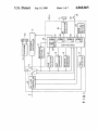
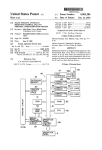
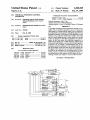
FIG. 1 is a block diagram of the structure of a termi
nal switching control apparatus according to a ?rst
30 embodiment of this invention;
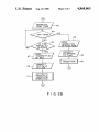
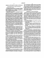
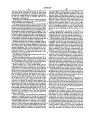
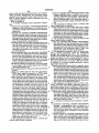
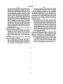
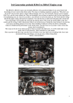
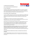
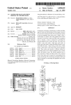
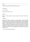
FIGS. 2A through 2C are ?owcharts for explaining
A controller ?rst responds to the call detect signal
the
operation of the ?rst embodiment;
from the call detector and outputs the switch control
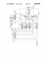
FIG. 3 is a block diagram of the structure of a termi
signal to the switching circuit so as to couple itself to
nal switching control apparatus according to a second
the communication line. The controller responds to the
facsimile communication end signal from the facsimile 35 embodiment of this invention;
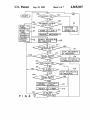
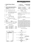
FIG. 4 is a flowchart for explaining the operation of
section to monitor the call detect signal from the call
the second embodiment; and
detector. In addition, the controller responds to the call
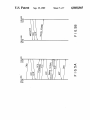
FIGS. 5A and 5B are sequence diagrams illustrating a
detect signal and sends a ?rst facsimile communication
facsimile communication and a telephone communica
control signal from the facsimile section on the commu
accordance with a record stop instruction.
nication line, then sends the record start instruction to 40 tion.
the recording section, and sends the record stop instruc
tion thereto upon elapse of a second time period as a
DETAILED DESCRIPTION OF THE
PREFERRED EMBODIMENTS
recording time. Upon reception of a second facsimile
Terminal switching control apparatuses according to
communication control signal during the second time
preferred
embodiments of this invention will be ex
period, the controller sends the record stop instruction 45
plained below, in conjunction with the accompanying
to the recording section to permit the facsimile section
drawings.
to perform the facsimilecommunication.
To begin with, referring to FIG. 1, the structure of
As described above, according to the terminal
the terminal switching control apparatus (TCU) ac
switching control apparatus of this invention, based on
cording to the ?rst embodiment of this invention will be
the presence or absence of an incoming CNG signal, it
explained. In FIG. 1, a circuit section such as a dial
is determined whether the caller requests a facsimile
communication through auto calling or a telephone
pulse generator, necessary for initiating the calling, and
communication through a telephone, and switching
those sections in a facsimile other than a facsimile con
and if the caller is a telephone, the user can assuredly
respond to the caller over the telephone.
If no off-hook operation is conducted by the user
even upon elapse of a predetermined time after a tele
periods T0, T1, T2, T3 and T4. Switch 11, which is also
included in TCU 1, has three switching nodes and is
troller are omitted for explanatory simplicity.
between the receiver’s facsimile and telephone is auto
In FIG. 1, TCU 1 has controller 16 which is mainly
matically done in accordance with the decision. There 55
constituted by a microprocessor and performs the over
fore, if the caller is an auto-calling facsimile, the facsim
all control of the apparatus. Controller 16 has timers 34,
ile communication can be performed in an auto recep
35, 36, 37 and 38, which respectively measure time
tion mode without requiring a user’s manual operation,
phone calling has started, the switch is automatically
switched between these nodes in accordance with a
switch control signal from controller 16, to establish a
channel. The common node of switch 11 is coupled to a
subscriber line 2 through DC loop controller 15. This
switched to the facsimile control section so as to pro
vide assured response even to a facsimile communica 65 controller 15 forms a DC loop of subscriber line 2 in
tion request done through manual calling by the caller.
Further, in the auto answering mode, when the caller
is a facsimile, irrespective of auto calling or manual
accordance with a loop-form control signal from con
troller 16 and sends a disconnect signal to controller 16
when a caller terminates the communication.
5
4,868,865
Of the three switching nodes of switch 11, node 3 is
coupled to telephone 31 equipped with a hand set 32.
Switch 33 is interlocked with the hook set so that it is
closed when hand set 32 is off-hooked. During on-hook
of hand set 32, therefore, a telephone communication
signal is supplied to controller 16. Node 2 is coupled to
facsimile controller 4. This controller 4 controls the
facsimile communication in accordance with a facsimile
communication start instruction from controller 16 and
sends a facsimile communication end signal to control
ler 16 upon completion of the facsimile communication.
Node 1 is coupled to CNG (calling tone) detector 12,
RBT (ring back tone) generator 13 and message genera
tor 14, which are all included in TCU 1. Node 1 is also
coupled to TCU 1 directly.
CNG detector 12 detects CNG sent from the caller’s
terminal after a calling signal is detected. Upon detec
tion of the CNG, detector 12 sends a CNG detect signal
to controller 16. RBT generator 13 generates a pseudo
ring back tone (RBT) in response to a RBT generation
instruction from controller 16 and sends the RBT to the
caller’s terminal. Message generator 14 generates a
6
from the communication signal, controller 16 sends the
switch control signal to switch 11 to connect the com
mon mode to node 1. When call detector 17 detects an
incoming calling signal, the process advances to step 3d;
otherwise, the process returns to step 30.
When a calling signal of 16 Hz sent from the ex
changer over line 2 is detected by call detector 17 in ,
step 30 in the wait state, the call detect signal is output
to controller 16 and step 3d is executed. In step 3d, DC
loop controller 15 forms a DC loop of subscriber line 2
in accordance with the loop-form control signal from
controller 16. This couples the caller and receiver
through the exchanger.
In step 3e, the currently-set operation mode is deter
15 mined. As the non-auto answering mode is currently
set, the decision in this step is negative (N) and the
subsequent step 3f will be executed. If the decision in
step 3e is affirmative (Y), then step 50 (FIG. 2c) will be
executed.
In step 3]; controller 16 sends out the message genera
tion instruction to message generator 14 and timer 34 is
started. In response to this instruction, message genera
voice message indicating the currently-specified opera
tor 14 generates a voice message indicating that the
tion mode in response to a message generation instruc
non-auto answering mode is set, and the generated mes
tion from controller 16 and sends the message to the 25 sage is sent on line 2 through switch 11 and controller
caller’s terminal. There are two operation modes set by
15. As a result, the caller is informed that either tele
a mode setting section 20: a non-auto answering mode in
phone or facsimile communication is available on the
which either a telephonereception or a facsimile recep
receiver side. In step 3g, time period T0, e.g., 10 sec
tion is possible and an auto answering mode in which an
onds, during which the message is being output, is mea
auto answering operation is ?rst initiated and the fac
sured by timer 34. If it is determined in step 3g that 10
simile reception can be initiated upon reception of the
seconds have elapsed, the transmission of the voice
CNG detect signal.
message is stopped and step 3h will be executed next.
TCU 1 further includes call detector 17 and ring tone
During
period T0, a ring back tone (RBT) has been
(RT) generator 18. Call detector 17 detects a 16 Hz
conventionally
fed back to the caller; in this embodi
calling signal incoming through subscriber line 2 from
ment, however, a message is transmitted to the caller
an exchanger (not shown) in a wait state. Upon detec
instead.
tion of the calling signal, detector 17 sends out a call
In step 3h, the RBT generation instruction is output
detect signal to controller 16. RT generator 18 gener
to
generator 13, which in turn generates and sends the
ates a signal for telephone calling in accordance with a
ring instruction from controller 16 and generates ring 40 pseudo ring back tone RBT to line 2 through switch 11
and controller 15. Consequently, the caller is informed
tone through a speaker 5 to inform a user of the tele
that TCU 1 is called. At this time, timer 35 is started in
phone calling.
step
3i and controller 16 monitors the elapsing of a
Recording section 6 is also coupled to node 1 and
given time period T1, e.g., 10 seconds, in step 3]. During
records an incoming analog voice signal in accordance
with a record start instruction from controller 16. This
recording section 6 may be a recording device such as a
tape recorder or may be constituted by an encoder and
a'RAM. This RAM may be the one provided in the
facsimile.
the time period T1, in step 3i, reception of the CNG
from the caller is monitored based on the CNG detect
signal from CNG detector 12. Here, the CNG signal is
the ?rst signal output from the caller’s facsimile before
initiating in the facsimile control sequence when the
Referring now to FIGS. 2A to 2C, the operation of 50 caller’s facsimile auto-calls, as shown in FIG. 5A, and is
output for 0.5 second at a frequency of 1100 Hz and is
TCU 1 according to the ?rst embodiment will be ex
interrupted for 3 seconds.
plained.
If, in this state, the reception of the CNG signal is
In a wait state, steps 3a to 3c are repeated and in these
detected within the given time T1, it is determined that
steps it is determined whether or not a mode setting key
the caller is a facsimile and the flow advances to step 3k
(not shown) of mode setting section 20 is operated,
from step 3i. In step 3k, controller 16 causes generator
whether or not the calling operation is to be performed
14 to stop sending the pseudo ring back tone RBT.
and whether or not an incoming calling signal is re
Then, a ?ow advances to step 31 where the controller 16
ceived. When controller 16 detects in step 30 that the
sends the switch control signal to switch 11 to connect
mode setting key is operated in the wait state, a mode
the common node to facsimile controller 4. Also, the
setting operation is executed in step 3m. Assume now
facsimile communication start instruction is output to
that the non-auto answering mode has been set. If it is
controller 4. As a result, in step 30, facsimile controller
determined in step 3b that hand set 32 is off-hooked, a
4 is coupled to subscriber line 2 and the facsimile com
communication signal is input to controller 16. In re
munication is thereafter performed between the caller’s
sponse to this signal, controller 16 sends the switch
control signal to switch 11 to connect the common node 65 facsimile and the receiver’s facsimile in accordance
with a known facsimile control sequence, as shown in
to node 2. Accordingly, a calling operation is executed
in step 3n and communication will be made as a conse
FIG. 5A. That is, the automatic facsimile-receiving
quence. When the end of communication is detected
operation is executed. Therefore, the user need not to
7
4,868,865
8
sage generator 14 generates a voice message indicating
that the auto answering mode is set, and sends it over
line 2 to the caller. The content of this message differs
from that of the message generated in step 3/: The trans
mission of the message continues for a given time period
perform any switching operation to the terminal appa
ratus.
When no CNG signal is detected within the given
time period T1, controller 16 determines that the caller
is a telephone and initiates the ?owchart as shown in
FIG. 213. First, in step 4a, controller 16 sends out the
ring instruction to RT generator 18 and starts timer 36.
Generator 18 generates a ring tone signal so that a ring
tone RT is output from speaker 5. In the subsequent step
4b, the off-hook operation of hand set 32 is monitored
on the basis of the telephone communication signal.
In this state, if the user picks up hand set 32 noticing
T3, e.g., 10 seconds. When elapse of the time period T3
is detected in step 5b, the flow advances to step 5c
where controller 16 sends the record start instruction to
recording section 6 to start the function of the recording
section 6 and starts timer 38. As a result, recording
section 6 records, for example, a speech made by the
the ring tone, controller 16 determines through switch
15
In addition to the recording control, the reception of
the CNG signal is monitored by detector 12 in step 5d.
When the reception of the CNG signal is detected
within a given time period T4, e.g., 20 seconds (step 5e)
and the CNG detect signal is sent to controller 16 from
20
and the ?ow advances to step Sfl In step 5f, the record
stop instruction is sent to recording section 6 and the
recording section stops its recording function. Then, in
step 5g controller 16 sends the switch control signal to
user on the caller side.
33 that the user is going to talk on the phone. As a
result, the ring tone is stopped in step 4d and controller
16 sends the switch control signal to switch 11 so as to
connect the common node to node 3 in step 4e. This
couples telephone 31 to subscriber line 2. Thereafter,
telephone communication is performed between tele
phone 31 and the caller’s telephone (step 4h), as shown
in FIG. 5B. That is, the switching to the telephone is
also automatic in this case. Therefore, if the caller is a
detector 12, it is determined that the caller is a facsimile
switch 11 to connect the common node to node 2 that is
telephone, the user can assuredly respond to the caller
coupled to controller 4. Controller 4 is also supplied
through the same operation as is done with ordinary
telephones. It should be noted here that the ring tone 25 with the facsimile communication start instruction.
informing the user of the incoming call is generated
upon elapse of time periods T0 and T1 after the calling
signal is actually received. No information is given to
the user until then.
When the end of the telephone communication is
con?rmed by the telephone communication signal, con
troller 16 sends the switch control signal to switch 11 to
couple line 2 to node 1 and returns to step 3a.
Consequently, the facsimile auto reception is carried
out thereafter in step 5h. Even in the auto answering
mode, therefore, the facsimile communication can be
assuredly made with the caller being facsimile. In this
case, the user also need not perform any switching oper
ation.
'
When the facsimile communication is completed, as
described above, the facsimile communication end sig
nal is sent to controller 16 and line 2 is coupled to node
It is determined whether any off-hook operation is
done during a given time T2, e.g., 20 seconds, after the 35 1.
If the caller aborts the call during each switching
generation of the ring tone in step 40. When no off-look
control operation mentioned above, controller 16 de
operation is done within this time period T2 (step 4c), it
tects this event from the output of a polarity inversion
is determined that the user is absent and the flow ad
detector (not shown) provided in DC loop controller
vances to the subsequent step 4]". In other words, the
caller may be requesting the facsimile communication 40 15, i.e., from a disconnection signal, and stops the con
trol operation at that time and returns to the wait state.
through the manual calling, so that upon elapse of the
given time period T2, the flow advances to step 4f
The present invention is not limited to the above
where the pseudo ring back tone RBT and the ring tone
are stopped. Then, the switch control signal is sent to
embodiment. For instance, the pseudo ring back tone
may be replaced with another type of tone signal or a
switch 11 to switch the common node to facsimile con 45 voice message that indicates the call being made. Fur
troller 4 in step 4g. As a result, subscriber line 2 is cou
pled to controller 4. In addition, controller 4 receives
the facsimile communication start instruction and thus
ther, when the communication mode requested by the
sends a CED (called station identification) signal to the
tion record each time. The above embodiment has been
explained with reference to a communication terminal
caller as shown in FIG. 5A. Thereafter, the facsimile
communication can be performed (step 41'), as shown in
caller is discriminated, the result may be displayed on a
display or may be stored in a memory as a communica
apparatus in which the facsimile, the telephone and the
FIG. 5A. Thus, if the caller has been requesting the
recording device with the auto answering function are
facsimile communication through the manual calling,
independently provided. However, a telephone with
the auto answering function may be integrated in the
therefore, the user on the caller side can con?rm this
facsimile. Furthermore, the switching control sequence
CED signal and can initiate the facsimile communica
and the contents of the control, the operation mode
tion thereafter.
informing means and the call discriminating/detecting
When the facsimile communication is ended, control
means can be modi?ed in various manners without
ler 4 sends the facsimile communication end signal to
departing from the scope of the invention.
controller 16, which in turn sends the switch control
In the above embodiment, line 2 is switched to node
signal to switch 11 to couple line 2 to node 1.
1 upon completion of a communication. However, line
If the operation mode of TCU 1 is set to the auto
2 may be coupled to node 1 when a call detect signal is
answering mode, the flowchart as shown in FIG. 2C
detected. Also, if the CNG detector, the RBT and mes
will be executed. When, after the forming of the DC
sage generators, and the controller 16 are directly cou
loop of subscriber line 2 in step 3d, it is determined in
step 3e that the auto answering mode has been set, the 65 pled to line 2, line 2 may be coupled to equipment to be
communicated with when a communication is started.
flow advances to step 5a where controller 16 sends the
Also, in the above embodiment, line 2 is coupled to
message generation instruction to message generator 14
telephone 31, facsimile controller 4, or recording sec
and starts timer 37. In response to this instruction, mes
4,868,865
tion 6 by switch 11 in accordance with the switch con
trol signal from controller 16. However, these three
devices may be connected to controller 16 and may be
10
the analog signal is being input, the recording operation
continues. When it is determined in step 61 that 3 sec
onds has been elapsed, the ?ow advances to the next
activated by a signal from the controller, respectively.
step 6m where it is determined whether or not a voice
In this case, switch 11 can be omitted, and line 2 is
connected to controller 16.
Referring now to FIGS. 3 and 4, a terminal switching
signal is detected by detector 19. When the voice detect
signal is input, the flow advances to step 60 where S0
time 39 is reset. When the voice detect signal is not
detected, the ?ow advances to step 6n where the fac
simile control sequence signal is sent to the caller.
Thereafter, step 6o>is executed. In the subsequent step
control apparatus according to the second embodiment
of this invention will be explained.
To being with, the structure of the second embodi
ment will be explained below, referring to FIG. 3. The
structure of the second embodiment is mainly the same
as that of the ?rst embodiment, so that only the differ
ences will be discussed here. Due to the difference in
the operation control, controller 16 is changed to con
troller 16'. Controller 16’ has an S0 timer 39 and an S1
timer 40 in place of timers 34 to 38. A message genera
tor 14‘, replacing message generator 14, is coupled be
tween node 1 and switch 11' and controller 16'. Switch
6;), it is determined whether or not 40 seconds have
elapsed. If the decision here is negative, the ?ow returns
to step 6i, and if it affirmative, the ?ow returns to step
60.
When communication interruption is detected by a
disconnect signal from controller 15 in steps 6i to 61,
controller 16’ sends the record stop instruction to re
cording section 6 in step 64, thereby stopping the re
cording operation. Then, the flow returns to step 6a.
When reception of the DCS signal as shown in FIG.
5A is detected in steps 6i to 61, the recording operation
11’ has node 1 coupled to facsimile controller 4 through
controller 16' and node 2 coupled to telephone 31.
is stopped in step 6r in the same manner as has been
Message generator 14’ generates a message different
explained, and the facsimile communication start in
from the one produced by message generator 14, in
struction is sent to controller 4 in order to initiate in the
accordance with the message generation instruction
from controller 16’. RBT generator 13 is not used in the 25 facsimile communication. Then, the facsimile communi
cation is performed as shown in FIG. 5A (step 6s).
second embodiment, but a vocal sound detector 19 is
Upon completion of the facsimile communication, the
instead coupled between node 1 of switch 11’ and con
facsimile communication end signal is sent to controller
troller 16’. Detector 19 detects the presence of an ana
16’ from controller 4, and the ?ow returns to step 6a
log signal on line 2 as a voice signal and sends a voice
As has been explained above, according to this em
30
detect signal to controller 16'.
bodiment, since recording section 6 is ?rst operated
The operation of the second embodiment will now be
when a call is detected, if telephone communication is
explained referring to FIG. 4.
requested by the caller, such communication can be
In the wait states in steps 60 and 6b, controller 16’ is
made. If, on the other hand, it is found that the caller
monitoring the off-hook of hand set 32 through switch
has intended facsimile communication, the operation for
33. When hand set 32 is off-hooked, the calling opera
making the telephone communication can be stopped to
tion is performed in step 6!. That is, the same operation
cope with the intended action. Therefore, the caller
as is done in step 3m of FIG. 2A is performed.
does not hear an unpleasant high tone signal which is
When reception of a 16 Hz calling signal from an
generated in facsimile communication, and the auto
exchanger (not shown) is detected by call detector 17
answering telephone can be used with the facsimile.
while hand set 32 is in the on-hook state, the call detect
If the caller aborts the calling operation during each
signal is sent to controller 16' in step 6c. Controller 16'
sends the loop-form control signal to DC loop control
switching control operation described above, controller
ler 15 to lock on subscriber line 2. In the subsequent step
16’ detects this event by a disconnect signal output from
6d, controller 16' sends the message generation instruc
a polarity inversion detector (not shown) provided in
DC loop controller 15, and stops the control operation
tion to message generator 14’, which in turn sends a 45
message to the caller through switch 11’ and controller
15, as shown in FIG. 5B. Then, S1 timer 40, which
measures the elapse of, for example, 40 seconds, is reset
in step 6e. In step 6f; S0 timer 39 which measures the
elapse of, for example, 3 seconds is reset. Then, in step
6g controller 16‘ sends the facsimile control sequence
signal to the caller. This corresponds to the transmission
of the CED (called station identi?cation) signal and
DIS (digital identification signal) signal in FIG. 5A. In
at that time and returns to the wait state.
Since the ?owchart shown in FIG. 4 has many por
tions similar to the flowcharts shown in FIGS. 2A to
2C, if the CNG detector and the RBT generator are
further provided in the second embodiment, the flow
chart of FIG. 4 may be incorporated in those shown in
FIGS. 2A to 2C. In this case, steps 6g, 6h to 6s need to
be executed in place of steps 5c to 5h, and steps 6g, 6i to
6p in place of steps 3i to 3j.
The present invention is not limited to the above
the next step 6h, controller 16’ sends the record start 55
embodiment. For instance, an RBT generator may be
instruction to recording section 6 and this recording
provided to send a pseudo ring back tone or the pseudo
section 6 starts recording a vocal sound received, as
ring back tone may be replaced with another type of
shown in FIG. 5B.
tone signal or a voice message that indicates the call
After the recording operation has started, S0 timer 39
measures 3 seconds in step 61. During this measuring 60 being made. Further, when the communication mode
requested by the caller is discriminated, the result may
operation, it is determined in steps 61‘ and 6] whether an
be displayed on a display or may be stored in a memory
incoming signal received over line 2 is a DCS (digital
as a communication record each time. The above em
command signal) generated in response to the facsimile
bodiment has been explained with reference to a facsim
control sequence signal, or a voice signal as an analog
signal or a non-vocal sound signal generated upon de 65 ile which incorporates a telephone with the auto an
swering function. However, the second embodiment
pression of the start switch of the facsimile on the caller
side. It is also checked in step 6k if the communication
can apply to a communication terminal apparatus in
is interrupted. When it is detected by detector 19 that
which the facsimile, the telephone and the recording
11
4,868,865
12
means for outputting said establish instruction to said
channel establish means to establish said second
device with the auto answering function are indepen
dently provided. Furthermore, the switching control
channel outputting said facsimile communication
sequence and the contents of the control can be modi
?ed in various manners without departing from the
scope of the invention.
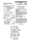
What is claimed is:
start instruction to said facsimile, when said tele
phone communication is not performed within a
third time period after elapse of said ?rst time per
1. A terminal switching control apparatus compris
mg:
a telephone for generating a communication signal in
response to the performance of a telephone com 10
munication through a ?rst channel and a communi
cation line;
iod.
3., The apparatus according to claim 1, wherein said
control means further comprises:
means responsive to one of said CNG detect signal
within said second time period and elapse of said
second time period, for outputting said record stop
instruction to said recording means, said establish
a facsimile for executing a facsimile communication
through a second channel and said communication
line in accordance with a facsimile communication
instruction to said channel establish means to estab
lish said second channel, and said facsimile commu
nication start instruction to said facsimile.
start instruction input thereto, and for generating a
4. The apparatus according to claim 3, wherein said
control means further comprises:
tion of said facsimile communication;
means for outputting said facsimile communication
recording means for recording communication data
start instruction to said facsimile and said establish
20
input through a third channel and said communica
instruction to said channel establish means to estab
tion line, in accordance with a record start instruc
lish said second channel when said telephone com
tion input thereto, and for stopping a recording
munication is not performed within a third time
operating in accordance with a record stop instruc
period after elapse of said ?rst time period.
tion input thereto;
5. The apparatus according to claim 1, further com
25
channel establish means for selectively establishing
prising message generating means for transmitting
one of said ?rst channel between said communica
through said communication line a ?rst message to
tion line and said telephone, said second channel
indicate that said ?rst mode is set, during a fourth time
between said communication line and said facsim
period, in response to a ?rst message generation control
ile, and said third channel between said recording 30 signal input thereto and a second message to indicate
means and said communication line, in accordance
that said second mode is set, during a ?fth time period,
with an establish instruction input thereto;
in response to a second message generation control
call detector means for generating a call detect signal
signal input thereto; and
in accordance with a calling signal input through
wherein said control means further comprises means
facsimile communication ends signal upon comple
said communication line;
35
mode setting means for setting one of ?rst and second
modes;
calling tone (CNG) detector means for generating a
CNG detect signal in response to a CNG signal
input through said communication line; and
for outputting said ?rst message generation control
signal to said message generating means before said
?rst time period when it is determined that said ?rst
mode is set, for starting said ?rst time period after
elapse of said fourth time period, for outputting
said second message generation control signal to
control means for monitoring said call detect signal
said message generating means before said second
time period when it is determined that said second
mode is set, and for starting said second time period
cation signal from said telephone and said facsimile
after elapse of said ?fth time period.
communication end signal from said facsimile, and 45 6. The apparatus according to claim 1, further com
for determining whether said ?rst mode of said
prising ring back tone (RBT) generating means for
second mode is set by said mode setting means in
generating a ring back tone in response to a RBT gener
accordance with said call detect signal from said
ation control signal and for transmitting said generated
call detector means; for outputting said facsimile
ring back tone through said communication line; and
from said call detector means in accordance with
one of said record stop instruction, said communi
communication start instruction to said facsimile, 50
outputting said establish instruction to said channel
wherein said control means further comprises means
for, when it is determined that said ?rst mode is set,
establish means to establish said second channel in
outputting said RBT generation control signal to
response to said CNG detect signal from said CNG
detector means within a ?rst time period, and for
outputting said establish instruction to said channel 55
said RBT generating means during said ?rst time
period or until said CNG detect signal is input from
said CNG detector means.
establish means to establish said ?rst channel to
7. A terminal switching control'apparatus compris
enable said telephone communication in response
to elapse of said ?rst time period, when it is deter
mined that said ?rst mode is set; and for outputting
mg:
a facsimile for executing a facsimile communication
through a communication line in response to a
said record start instruction to said recording
means and said establish instruction to said channel
establish means to establish said third channel, and
facsimile communication start instruction input
generating and outputting to said recording means
said record stop instruction, in accordance with
elapse of a second time period when it is deter 65
mined that said second mode is set.
2. The apparatus according to claim 1, wherein said
control means further comprises:
thereto and for generating a facsimile communica
tion end signal upon completion of said facsimile
communication;
recording means for recording communication data
input through said communication line in accor
dance with a record start instruction input thereto,
and for stopping a recording operation in accor
dance with a record stop instruction input thereto;
13
4,868,865
14
call detector means for generating a call detect signal
10. The apparatus according to claim 9, further com
in accordance with a calling signal input through
said communication line;
ing a CNG detect signal in response to a CNG signal
prising CNG (calling tone) detector means for generat
input through said communication line; and
data detector means for detecting that said communi
cation data is being input through said communica
wherein said control means further comprises means
for outputting said record stop signal to said re
cording means and said facsimile communication
start instruction to said facsimile in response to said
tion line, and for generating a data detect signal;
and
control means for outputting a ?rst facsimile control
signal through said communication line once dur
ing a ?rst time period, in response to said call de
tect signal from said call detector means, said ?rst
time period being repeated within a second time
period, for outputting said record start instruction
to said recording means, for outputting said record
stop instruction to said recording means upon
11. The apparatus according to claim 9, further com
prising message generating means for transmitting a
message through said communication line in response to
a message generation control signal input thereto; and
elapse of said second time period, for outputting
said record stop instruction to said recording
signal before beginning of said ?rst'time period,
means and said facsimile communication start in
struction to said facsimile in accordance with a
and for starting said ?rst time period after transmit
ting said message.
12. A terminal switching control apparatus compris
second facsimile control signal input through said
CNG detect signal from said CNG detector means -
during said ?rst time period.
wherein said control means further comprises means
for generating said message generation control
20
communication line during said second time per
iod, for outputting said record stop instruction to
ing:
a telephone for generating communication signal in
said recording means in response to inactivation of
said data detect signal output from said data detec
tor means during said record second time period, 25
and for monitoring said call detect signal from said
call detector means in response to one of elapse of
said second time period and said facsimile commu
nication end signal from said facsimile.
8. The apparatus according to claim 7, further com
prising message generating means for transmitting a
message through said communication line in response to
a message generation instruction input thereto; and
start instruction input thereto, and for generating a
dance with a record start instruction input thereto,
and for stopping a communication data recording
operation in accordance with a record stop instruc
for outputting said message generation instruction
to said message generating means in response to
said call detect signal, before said second time per
iod.
tion input thereto;
channel establish means for selectively establishing
one of said ?rst channel between said communica
9. A terminal switching control apparatus compris
ing:
a facsimile for executing a facsimile communication
- through a communication line in response to a
facsimile communication start instruction input
thereto, and for generating a facsimile communica—
tion end signal upon completion of said facsimile 45
communication;
recording means for recording communication data
input through said communication line in accor
dance with a record start instruction input thereto,
and for stopping a recording operation in accor
dance with a record stop instruction input thereto;
call detector means for generating a call detect signal
modes;
data detector means for detecting that said communi
cation data is being input through said communica
tion line, and for generating a data detect signal;
data detector means for detecting that said communi 55
cation data is being input through said communica
tion line, and for generating a data detect signal;
and
control means including ?rst means for monitoring
said call detect signal from said call detector means
in response to one of said record stop instruction,
said communication signal from said telephone,
and said facsimile communication end signal from
said facsimile and for determining whether said
and
control means for outputting said record start instruc
tion to said recording means in response to said
detect signal from said call detector means, for
?rst mode or said second mode is set by said mode
outputting said record stop signal to said recording
means and said facsimile communication start in
struction to said facsimile upon elapse of a ?rst time
facsimile communication end signal from said fac
simile.
tion line and said telephone, said second channel
between said communicationqline and said facsim
ile, and said third channel between said communi
cation line and said recording means, in accordance
with an establish instruction input thereto;
call detector means for generating a call detect signal
in accordance with a calling signal input through
said communication line;
mode setting means for setting one of ?rst and second
in accordance with a calling signal input through
said communication line;
from said call detector means in response to said
cation line;
a facsimile for executing a facsimile communication
through a second channel and said communication
line in accordance with a facsimile communication
facsimile communication end signal upon comple
tion of said facsimile communication;
recording means for recording communication data
input through said communication line, in accor‘
wherein said control means further comprises means
period, and for monitoring said call detect signal
response to the performance of a telephone com
munication through a ?rst channel and a communi
65
setting means, in response to said call detect signal
from said call detector means; means, when it is
determined by said ?rst means that said ?rst mode
is set, for outputting a ?rst facsimile control signal
through said communication line once every ?rst
time period repeated within a second time period,
for outputting said establish instruction to said
channel establishment means to establish said sec
15
4,868,865
16
0nd channel and said facsimile communication start
said second facsimile control signal input through
instruction to said facsimile, in response to a second
said communication line within said fourth period.
15. The apparatus according to claim 12, further
comprising message generating means for transmitting
facsimile control signal input through said commu
nication line within said second time period, and
for outputting said establish instruction to said
channel establishment means to establish said ?rst
channel to enable said telephone communication in
' response to elapse of said second time period; and
means, when it is determined by said ?rst means
that said ?rst mode is set, for outputting said record
through said communication line a ?rst message indicat
ing that said ?rst mode is set, during a sixth time period,
in response to a ?rst message generation control signal
input thereto and a second message indicating that said
second mode is set, during a seventh time period, in
10 response to a second message generation control signal
start instruction to said recording means and said
establish instruction to said channel establishment
means to establish said third channel, for output
input thereto; and
wherein said control means further comprises means
for outputting said ?rst message generation control
signal to said message generating means before said
communication line once every third time period
second time period when it is determined that said
repeated within a fourth time period, and for gener
?rst mode is set, for starting said second time per
ating and outputting to said recording means said
iod after said sixth time period, for outputting said
record stop instruction in response to elapse of said
second message generation control signal to said
fourth time period.
message
generating means before said fourth time
13. The apparatus according to claim 12, wherein said 20
period when it is determined that said second mode
control means further comprises:
is set, and for starting said fourth time period after
means for outputting to said facsimile said establish
said seventh time period.
instruction to said channel establishment means to
16.
The apparatus according to claim 12, further
establish said second channel and said facsimile
communication start instruction when said tele 25 comprising RBT generating means for generating a ring
back tone in response to a RBT generation control
phone communication is not performed within a
signal input thereto, and for transmitting said generated
?fth time period after elapse of said second time
ring
back tone through said communication line; and
period.
wherein said control means further comprises means
14. The apparatus according to claim 12, wherein said
ting said ?rst facsimile control signal through said
control means further comprises:
means for outputting said record stop instruction to
said recording means, said establish instruction to
said channel establishment means to establish said
second channel, and said facsimile communication
start instruction to said facsimile, in response to 35
45
50
55
65
for outputting said RBT generation control signal
to said RBT generating means during said second
time period or until said second facsimile control
signal is input through said conmiunication line,
when it is determined that said ?rst mode is set.
i
*
i
ll
#