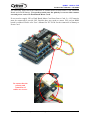
1
ROBOT . HEAD to TOE
Product User’s Manual – IFC-BH02
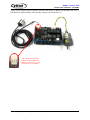
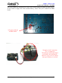
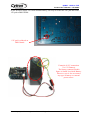
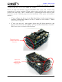
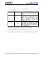
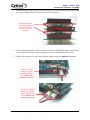
f. Connect the External power source for Dual Brush Motor Card. Please refer hardware
setup in chapter 5.0 for connecting power to Dual Brush Motor Card. Please ensure
the external power supply voltage selection’s pad on BH02 board is correctly soldered
according to power supply voltage.(12V or 24V)
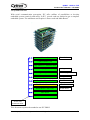
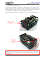
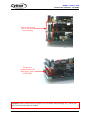
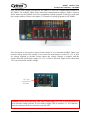
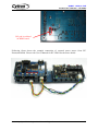
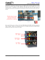
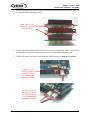
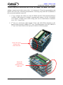
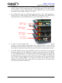
g. Turn ON the IFC power by pushing the toggle switch to “ON”. There should be at
least 3 LED (12V LED on Power Card, PWR LED on Main Brain and PWR LED on
Dual Brush Motor Card) light up as shown.
PWR LED on
IFC – BH02
PWR LED on
IFC - MB00
12V LED on
IFC - PC00
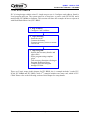
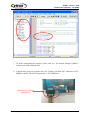
h. 3rd step is to write program and load it. IFC comes with comprehensive function to
reduce program development time. Functions library will come with the interfacing
card in the form of header file (*.h) and object file (*.o). In order to call these
functions, particular header file and object file must be included under a project.
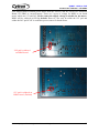
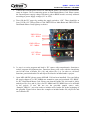
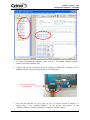
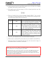
i. Open MPLAB IDE (please ensure MPLAB C18 has been installed). User can follow
the step in chapter 6.2 of IFC-MB00 user manual to open project named “IFC-BH02”
for IFC Dual Brush Motor Card. Please note that the header file (iic.h and iic_bh.h)
and object file (iic.o and iic_bh.o) for IFC-MB00 and IFC-BH02 have to be included
in the project. If user did not use the provided sample source code,
“Sample1_BH02.c”, user also needs to include card’s header file at the beginning of
the program. Figure below shows the example to include header file, object file and
card’s header file.
Created by Cytron Technologies Sdn. Bhd. – All Rights Reserved
25