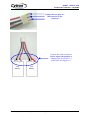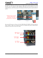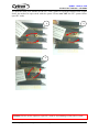
1
IFC-BH02
Interface Free Controller
Dual Brush Motor
User’s Manual
V1.0
Jan 2009
Information contained in this publication regarding device applications and the like is intended through suggestion only and may
be superseded by updates. It is your responsibility to ensure that your application meets with your specifications. No
representation or warranty is given and no liability is assumed by Cytron Technologies Incorporated with respect to the accuracy
or use of such information, or infringement of patents or other intellectual property rights arising from such use or otherwise. Use
of Cytron Technologies’s products as critical components in life support systems is not authorized except with express written
approval by Cytron Technologies. No licenses are conveyed, implicitly or otherwise, under any intellectual property rights.
ROBOT . HEAD to TOE
Product User’s Manual – IFC-BH02
Index
1. Introduction and Overview
1
1.1 Introduction of Interface Free Controller
1
1.2 System Overview
2
2. Packaging List
3
3. Product Specification
4
3.1 Communication Address
4
3.2 Programmer
4
3.3 Input and Output device
4
3.4 Operating Voltage
4
4
Board or Product Layout
5
5
Installation (hardware)
7
6
Installation (software)
21
7
Getting Started
22
7.1 Basic Setup (IFC-PC00 + IFC-MB00 + IFC-BH02)
23
7.2 Basic Setup with Control Panel (IFC-PC00 + IFC-MB00 + IFC-BH02
+ IFC-CP04)
8. Warranty
Created by Cytron Technologies Sdn. Bhd. – All Rights Reserved
28
33
ROBOT . HEAD to TOE
Product User’s Manual – IFC-BH02
1. INTRODUCTION AND OVERVIEW
1.1 Introduction of Interface Free Controller
IFC (Interface Free Controller) offer a new concept of developing microcontroller embedded
system and also robotics system. With IFC, no more frustration in determine hardware
interface and configuring peripheral in software. Checking few hundreds pages of data sheet
can be waved. With the concept of interfacing card, user may stack as many as 64 cards in a
system to get infinite combination of peripherals. The design aims to offer 3 simple steps in
microcontroller system development – Configure card’s address, Stack IFC cards, Write
Program and Run!
Furthermore, with functions based software library, user save valuable time during software
development by concentrating on algorithm development. No more flipping or scrolling PIC
data sheet looking for ADCON0, T1CON or even TRISA. With just a programming hand
book, user may simply copy the header file, call comprehensive functions and it’s ready to
rock.
IFC come with a brain card (main controller) where the main program is loaded. There are
several cards available for robotics development such as control panel, 15A brush motor
driver, brushless motor controller, counter and digital input, output card, Play Station 2
Controller card, analog input card, dual brush motor card and power card. This document will
focus on the dual brush motor card, IFC-BH02. This card has been designed with capabilities
and features as below:
• Industrial grade PCB.
• Every component is soldered properly and tested before board is shipped.
• Circuit power and busy indicator LED.
• 12V operation.
• 6 set of 1x3 headers to select communication address.
• 2 brush motor ports.
• 2 encoder ports.
• Selectable power source for encoder (5V, 12V or 24V).
• Drive brush motor in 2 different ranges of voltage (12v or 24 V), default is 12V.
• 2 motor status indicator LED to indicate the direction of motor (CW and CCW).
• “Motor Power In” status indicator LED.
• Maximum of 5A continuous current output per channel.
• Control each channel of motor independently for start, stop, speed and direction.
• Dimension 11.1cm x 6.9cm
• Template and sample source code is provided for MPLAB C18 compiler.
Warning: This card is not suitable for fast direction changing application due to some
timing delay needed when changing the motor direction using onboard relays.
Created by Cytron Technologies Sdn. Bhd. – All Rights Reserved
1
ROBOT . HEAD to TOE
Product User’s Manual – IFC-BH02
1.2 System Overview
With serial communication perception, IFC offer million of possibilities to develop
embedded system creatively and easily. In IFC, several cards are stacked to get a complete
embedded system. The minimum card requires is Power card and Main Board.
More cards
More devices
Control Panel Card
Play station 2 Controller card
Analog Input Card
Analog sensor
Digital Input Card
Encoder, digital sensor
Output Card
Brushless Motor Card
Relays, etc
Brushless motors
Dual Brush Motor Card
2 Brush motors
Brush Motor Card (15A)
Brush motor
Main Brain
Power card
Power and
communication
This document explains the method to use IFC-BH02.
Created by Cytron Technologies Sdn. Bhd. – All Rights Reserved
2
ROBOT . HEAD to TOE
Product User’s Manual – IFC-BH02
2. PACKAGING LIST
Please check the parts and components according to the packing list. If there are any parts
missing, please contact us at [email protected] immediately.
1. 1 x IFC Dual Brush Motor Card ,IFC-BH02 with:
• 7 x mini jumper.
• 1 x Female Connector (3961-03)
• 2 x Female Connector (3961-02)
• 2 x Female Connector (2510-03)
• 7 x 3961 iron pin
• 6 x 2511 iron pin
Created by Cytron Technologies Sdn. Bhd. – All Rights Reserved
3
ROBOT . HEAD to TOE
Product User’s Manual – IFC-BH02
3. PRODUCT SPECIFICATION
3.1 Communication Address
There are 64 (26) communication address of IFC-BH02 that can be selected. The 6 bits
communication address is determine by selector A5 through A0 (6 set of 1x3 headers on IFCBH02). User may set the card address by using the mini jumper. However, user is required to
make sure the communication address chosen on board is compatible with program written in
Main Board.
3.2 Programmer
User does not need to prepare programmer for IFC-BH02. IFC-BH02 is one of the slave
cards of IFC system. The slave program is preloaded before shipped to customer. User will
only need the Main Board of IFC system, IFC-MB00 to control this slave card.
3.3 Input and Output device
The output devices on BH02 are as below:
• 2 status indicator LED: Power and busy LED:
- Power LED (PWR) will turn ON when power is supplied to BH02.
- Busy LED (Busy) will turn ON or blinking when BH02 is communicating
with master card, IFC-MB00.
• Motor Power In status indicator LED.
• 2 brush motor port to connect brush motor. The brush motor connected can run up
to 5A per channel. BH02 will be solder at 12V for motor voltage option in
default. However, user may de-solder the 12V pad and solder 24V pad if motor
used is rated at 24V.
• 2 motor’s direction indicator LED for each motor, clockwise (CW) and counterclockwise (CCW).
The input devices on BH02 are as below:
• 2 encoder input port ready with selectable power source:
- Selectable power source for encoder input port (5V, 12V or 24V). User
can select the encoder power source by using the mini jumper.
3.4 Operating Voltage
• The operation voltage of IFC-BH02 is 12V. User needs to stack a Power Card, IFCPC00, and connect a 12V battery on Power Card to supply 12V to Dual Brush
Motor Card. However, user needs to connect external power source through Power
In connector on IFC-BH02 to supply voltage to brush motor. The Motor Power In
status indicator LED will turn ON when either 12V or 24V external power is
connected. User may connect external power source from IFC Power Card (IFCPC00), IFC Extension Board (IFC-EB02) or external battery. There are 2 types of
voltage for BH02 to run brush motor, which are 12V and 24V. By default, BH02
will be solder at option 12V. However, user can de-solder the 12V pad and solder
24V pad if 24V is needed as voltage input. However, please be caution! Only 1
power pad can be soldered each time.
Created by Cytron Technologies Sdn. Bhd. – All Rights Reserved
4
ROBOT . HEAD to TOE
Product User’s Manual – IFC-BH02
4. BOARD OR PRODUCT LAYOUT
B
C
C
D
A
E
P
O
N
F
G
O
F
G
G
M
L
H
L
Label
A
B
C
D
E
F
G
H
K
Function
Encoder connectors
Encoder voltage selector
Motor’s direction indicator LED
Brush Motor connectors
Orientation marking
Relays
Side connector
Motor Power In connector
J
Label
I
J
K
L
M
N
O
I
H
Function
Motor Power In status indicator LED
Fuse and fuse holder
Communication address selectors
Status indicator LED
Manufacturing Test Points
PIC Microcontroller
Arrow
A – Connector for encoder. User can connect 5V, 12V or 24V encoder with suitable voltage
pre-selected. Please ensure the pins are correct when connect encoder to the board. Please
refer to the marking at the back of connector for wiring polarity and signal.
B – Encoder voltage selector. User can use the mini jumper to select 5V, 12V or 24V for
voltage supplied to encoder. Please ensure the voltage selected is suitable with the encoder
before powering up the board and only ONE input voltage range (5V, 12V or 24V) is
selected.
C – 2 Motor’s direction indicator LEDs for each motor. The CW LED will turn ON when
motor run in clockwise while CCW LED will turn ON when motor run in counter-clockwise.
Created by Cytron Technologies Sdn. Bhd. – All Rights Reserved
5
ROBOT . HEAD to TOE
Product User’s Manual – IFC-BH02
D – The connector to connect brush motor. The brush motor connected can run up to 5A for
each motor.
E – The orientation marking on IFC-BH02. Every IFC card will have this orientation
marking, this is to help user in ensuring the cards are stack correctly.
F – Relay for driving brush motor. Each motor need 2 relay to drive motor in CW and CCW
direction.
G – Side connector for stack card and communication between cards.
H – Motor Power In connector for user to connect external power source for motor. The
external power source must be provided to IFC-BH02 in order to run motor. User may
connect it using the standard connector provided. The voltage for motor will also depends on
pad soldered on the BH02 card either 12V or 24V. Only 1 input can be soldered as input.
I – Motor Power In status indicator LED. The Motor Power In status indicator LED will turn
ON when either 12V or 24V external power is connected.
J – 15A fuse used as motor control circuit protection.
K – 6 set of 1x3 headers use as communication address selector on IFC-BH02. User can set
the card address by using the mini jumper.
L – 2 status indicator LEDs are used to indicate the status for power ON (PWR) and busy in
communicating with Main Board card (Busy). PWR LED will turn ON when power supplied
to the board. Busy LED will turn ON when the card is busy in communicating with master
card, IFC-MB00.
M – Reserved for Manufacturing Test Point. Please DO NOT short or connect wire to any of
these pins.
N – Microcontroller which used as controller for this slave card.
O – An arrow to help user in ensuring the cards are stack correctly. Every IFC card has this
arrow; user needs to ensure that the arrow points to the same direction when IFC cards are
stack together.
Cautions: Only ONE power input (12V or 24V) can be soldered on BH02 board as
power source for motor. If user accidently solders both pad to power input, the PC00 and
battery will be damaged.
Created by Cytron Technologies Sdn. Bhd. – All Rights Reserved
6
ROBOT . HEAD to TOE
Product User’s Manual – IFC-BH02
5. INSTALLATION (HARDWARE)
For the hardware installation of IFC-BH02, user will first need the Main Board card (IFCMB00) and Power Card (IFC-PC00) of IFC system. IFC-MB00 is the main controller of the
IFC system while IFC-PC00 is the main power supply of the system. For the installation of
IFC-MB00 and IFC-PC00 please refer to the user’s manual of IFC-MB00.
After user obtain the IFC-BH02, user can stack it on IFC system as shown in figure below.
Ensure the arrow
points to the same
direction.
Ensure the
orientation
marking at the
same side.
Cautions: Please ensure that every card is being stacked properly in correct orientation.
Whole IFC system will be damaged if one of the cards is being stacked wrongly when it
is powered up.
Created by Cytron Technologies Sdn. Bhd. – All Rights Reserved
7
ROBOT . HEAD to TOE
Product User’s Manual – IFC-BH02
Besides stack every card in correct orientation, user must also require to ensure all card pins
are not shifted when stacking. Figures show the example of stacking cards in proper location
and example of stacking cards with shifted pins.
Ensure that all card
pins are not shifted
when stacking.
Examples of
stacking cards with
shifted pins. Please
AVOID this!
Created by Cytron Technologies Sdn. Bhd. – All Rights Reserved
8
ROBOT . HEAD to TOE
Product User’s Manual – IFC-BH02
Ensure that all card
pins are not shifted
when stacking.
Examples of
stacking cards with
shifted pins. Please
AVOID this!
Cautions: Please ensure that all card pins are not shifted when stacking. IFC system will
NOT function if the pins are shifted.
Created by Cytron Technologies Sdn. Bhd. – All Rights Reserved
9
ROBOT . HEAD to TOE
Product User’s Manual – IFC-BH02
User can use mini jumper provided on IFC-BH02 to select the communication address of
IFC-BH02. For example, figure below shows the communication address, 000011 selected.
Please make sure the address selected is compatible with the program. Each slave card must
have unique address. Please refer chapter 7 for details of writing program for IFC-BH02.
User also needs to select power source for the encoder if it is connected to BH02. There is an
encoder voltage selector for encoder. User can use the mini jumper to select 5V, 12V or 24V
for voltage supplied to encoder. Please ensure the voltage selected is suitable with the
encoder and only ONE input voltage (5V, 12V or 24V) is selected. Figure below shows that
12V was selected for encoder voltage.
12V was
selected for
Encoder.
Caution: Please ensure that only ONE input voltage range (5V, 12V or 24V) selected for
each encoder voltage selector. If user need to supply 24V to encoder, 2 x 12V batteries
must be connected to Power Card or to provide 24V.
Created by Cytron Technologies Sdn. Bhd. – All Rights Reserved
10
ROBOT . HEAD to TOE
Product User’s Manual – IFC-BH02
Figure below shows how to connect Encoder and motor to BH02. Each BH02 can drive 2
brush motors independently. The encoder voltage was selected at 12V.
Do ensure that the pins
connected to encoder are
correct. (+) for VCC, (-) for
GND and (s) for signal.
Created by Cytron Technologies Sdn. Bhd. – All Rights Reserved
11
ROBOT . HEAD to TOE
Product User’s Manual – IFC-BH02
User should connect external power source from IFC Power Card, IFC-PC00, IFC Extension
Board, IFC-EB02 or external battery. There are 2 types of voltage for BH02 to run brush
motor, which are 12V and 24V. Please ensure the supply voltage is suitable for the motor.
BH02 will be soldered at 12V by default. However, user may de-solder the 12V pad and
solder the 24V pad if 24V is needed as power source for brush motor.
24V pad is soldered
on BH02 board.
12V pad is soldered on
BH02 board. (Default)
Created by Cytron Technologies Sdn. Bhd. – All Rights Reserved
12
ROBOT . HEAD to TOE
Product User’s Manual – IFC-BH02
The following figures show the connection of external Power In from Power Card, Extension
Board and external battery. User needs to make sure the polarity is correct when connect
external power source for Dual Brush Motor Card.
If user need to supply 24V to Dual Brush Motor Card from Power Card, 2 x 12V batteries
must be connected to provide 24V. Besides that, user needs to ensure 24V pad on BH02
board is soldered. Please refer User’s Manual for IFC-PC00 for the connection of battery to
Power Card.
Do ensure that the
polarity and
connection of
cables are correct.
Created by Cytron Technologies Sdn. Bhd. – All Rights Reserved
13
ROBOT . HEAD to TOE
Product User’s Manual – IFC-BH02
24V pad is soldered
on BH02 board.
Following figure shows the example connection of external power source from IFC
Extension Board. Please refer User’s Manual for IFC-EB02 for the more details.
Created by Cytron Technologies Sdn. Bhd. – All Rights Reserved
14
ROBOT . HEAD to TOE
Product User’s Manual – IFC-BH02
User may connect the external power source from external battery as shown in figures below.
If user needs to supply 24V from external battery, ensure 24V pad is soldered on BH02
board.
24V pad is soldered
on BH02 board.
Example of 24V connection
(2 x 12V Batteries).
The batteries connected in figure
are Sealed Lead Acid Battery.
However, user is free to connect
any type of battery as external
Created by Cytron Technologies Sdn. Bhd. – All Rights Reserved
15
ROBOT . HEAD to TOE
Product User’s Manual – IFC-BH02
If user needs to supply 12V from external battery, user may de-solder the 24V pad and solder
12V pad to BH02 board.
12V pad is soldered on
BH02 board.
Example of 12V connection
(1 x 12V Battery).
The battery connected in this
figure is Sealed Lead Acid Battery.
However, user is free to connect
any type of battery as external
power source.
Created by Cytron Technologies Sdn. Bhd. – All Rights Reserved
16
ROBOT . HEAD to TOE
Product User’s Manual – IFC-BH02
User may follow the steps below to build a cable connector for connecting the external power
source from 2 extra batteries.
Materials needed:
a. 4 x cable
b. 1 x 3961-3 female
connector
c. 3 x 3961 iron pins
2
1
3
Solder some
lead on it.
5
4
Insert into 3961
connector.
6
Solder some
lead on it.
7
8
9
Insert into 3961
connector.
Solder another
cable on it.
11
10
Solder some
lead on it.
12
Insert into 3961
connector.
Created by Cytron Technologies Sdn. Bhd. – All Rights Reserved
17
ROBOT . HEAD to TOE
Product User’s Manual – IFC-BH02
Ensure the iron pins are
fully inserted to the
connector
Connect the cable to batteries.
Please ensure the polarity is
correct. Red for positive (+)
while black for negative (-).
-
+
12V
Battery
-
+
12V
Battery
Created by Cytron Technologies Sdn. Bhd. – All Rights Reserved
18
ROBOT . HEAD to TOE
Product User’s Manual – IFC-BH02
After power is connected to Motor Power in, the Motor Power In status indicator LED will
turn ON. The Motor Power In status indicator LED will turn ON no matter 12V or 24V
external power is connected. If the indicator LED does not turn ON when power is
connected, please check the polarity and connection, DO NOT proceed to turn on the IFC
system.
The Motor Power In status
indicator LED turn ON
when either 12V or 24V
external power is connected.
Next, turn ON the power on Power Card, the PWR LED of IFC-BH02 will ON as shown in
Figure. Initially, if there are no functions related to IFC-BH02 being called in Main Board’s
program, the busy LED will not ON or blink.
PWR LED on
IFC – BH02
PWR LED on
IFC - MB00
12V LED on
IFC - PC00
Created by Cytron Technologies Sdn. Bhd. – All Rights Reserved
19
ROBOT . HEAD to TOE
Product User’s Manual – IFC-BH02
To open the cards, user should use the IFC card’s opener to open the stacked cards. Figure
shows the method to open cards with the opener. Please turn OFF the IFC system before
open IFC cards.
1
2
3
Caution: Please use the opener to open IFC cards to avoid damage of the pins or cards.
Created by Cytron Technologies Sdn. Bhd. – All Rights Reserved
20
ROBOT . HEAD to TOE
Product User’s Manual – IFC-BH02
6. INSTALLATION (SOFTWARE)
User need only to write program for IFC-MB00 in order to send data and communicate with
IFC-BH02. A program editor, C compiler and UIC00A software are required to be installed
in order for user to write program, compile it and load the program to IFC main board. User
is recommended to use MPLAB IDE as source code editor and MPLAB C18 as C compiler.
Both of the softwares are available for free download from Microchip website. Please refer
user’s manual of IFC-MB00 for the installation of MPLAB IDE and MPLAB C18. As for the
installation of UIC00A software, please refer to UIC00A User’s Manual.
Please refer to MB00 User’s Manual, Chapter 6 for details step to install MPLAB IDE and
C18 compiler.
Created by Cytron Technologies Sdn. Bhd. – All Rights Reserved
21
ROBOT . HEAD to TOE
Product User’s Manual – IFC-BH02
7. GETTING STARTED
IFC is being design with the aim of 3 simple steps to use it. Configure card address, Stack it,
Load program and run. The system must be at least have a power card (IFC-PC00) and a
main board (IFC-MB00) to function. This section will show the example on how to operate it
with Dual Brush Motor card, IFC-BH02.
1st step: Address
- Configure Card’s address
2nd step: Stacking
- Stack the card/s
- Connect the battery
- Connect necessary sensor or motor
- Turn it ON
3rd step: Program
- Include the necessary header and
object file/s
- Write program using template
given
- Call necessary function referring to
Program Reference Notes
- Compile and Load Program
through UIC00A
There are 2 basic setups in this chapter for IFC-BH02; the 1st example includes 3 cards, IFCPC00, IFC-MB00 and IFC-BH02, while 2nd example includes one extra card, which is IFCCP04. Please refer to the following section of this chapter for setup details.
Created by Cytron Technologies Sdn. Bhd. – All Rights Reserved
22
ROBOT . HEAD to TOE
Product User’s Manual – IFC-BH02
7.1 Basic Setup (IFC-PC00 + IFC-MB00 + IFC-BH02)
This is the basic and minimum setup for IFC-BH02 which comes with 2 brush motor
terminals and 2 encoder terminals. Though without other card, this basic setup can still
perform some task such as drive 2 brush motors or controlling the motor based on value
counted in encoder. Following steps show the installation of this system and method to
operate it.
a. 1st step, configure the address of card. Dual Brush Motor Card has 6 mini jumpers to
configure communication address (A5-A0). It should be set to 000011 if sample
source code is being used.
b. 2nd step is to stack all 3 cards together. Power card (IFC-PC00) should be at the
bottom, while Main board (IFC-MB00) at 2nd layer and Dual Brush Motor Card (IFCBH02) at top layer as shown in following figure.
Ensure the arrow
points to the same
direction.
Ensure the
orientation
marking at the
same side.
Created by Cytron Technologies Sdn. Bhd. – All Rights Reserved
23
ROBOT . HEAD to TOE
Product User’s Manual – IFC-BH02
c. Besides stacking every card in correct orientation, user must ensure all card’s pins are
not shifted when stacking the cards.
Ensure that all card
pins are not shifted
when stacking.
d. Connect the brush motor and encoder (if necessary) to Dual Brush Motor Card. Please
refer hardware setup for connecting input devices to Dual Brush Motor Card.
e. Connect the battery to Power card as shown; please ensure the polarity is correct.
Connect 1 x 12V
battery to supply
operating voltage to
IFC. Ensure the
polarity is correct.
If 24V is needed in
the system, connect
2 x 12V batteries to
PC00. Ensure the
polarity is correct.
Created by Cytron Technologies Sdn. Bhd. – All Rights Reserved
24
ROBOT . HEAD to TOE
Product User’s Manual – IFC-BH02
f. Connect the External power source for Dual Brush Motor Card. Please refer hardware
setup in chapter 5.0 for connecting power to Dual Brush Motor Card. Please ensure
the external power supply voltage selection’s pad on BH02 board is correctly soldered
according to power supply voltage.(12V or 24V)
g. Turn ON the IFC power by pushing the toggle switch to “ON”. There should be at
least 3 LED (12V LED on Power Card, PWR LED on Main Brain and PWR LED on
Dual Brush Motor Card) light up as shown.
PWR LED on
IFC – BH02
PWR LED on
IFC - MB00
12V LED on
IFC - PC00
h. 3rd step is to write program and load it. IFC comes with comprehensive function to
reduce program development time. Functions library will come with the interfacing
card in the form of header file (*.h) and object file (*.o). In order to call these
functions, particular header file and object file must be included under a project.
i. Open MPLAB IDE (please ensure MPLAB C18 has been installed). User can follow
the step in chapter 6.2 of IFC-MB00 user manual to open project named “IFC-BH02”
for IFC Dual Brush Motor Card. Please note that the header file (iic.h and iic_bh.h)
and object file (iic.o and iic_bh.o) for IFC-MB00 and IFC-BH02 have to be included
in the project. If user did not use the provided sample source code,
“Sample1_BH02.c”, user also needs to include card’s header file at the beginning of
the program. Figure below shows the example to include header file, object file and
card’s header file.
Created by Cytron Technologies Sdn. Bhd. – All Rights Reserved
25
ROBOT . HEAD to TOE
Product User’s Manual – IFC-BH02
j. To better understand the program, please refer to c file named “Sample1_BH02.c”
which is provided with this card.
k. Compile this project to generate hex file. Connect UIC00A IDC connector to IFCMB00 as shown. The hex file generated is “IFC-BH02.hex”.
Connector for UIC00A
programmer
Created by Cytron Technologies Sdn. Bhd. – All Rights Reserved
26
ROBOT . HEAD to TOE
Product User’s Manual – IFC-BH02
l. Load the generated hex file using PICkit2 window (refer to UIC00A User’s Manual
for details). Power up IFC system if it is OFF.
m. There are also 3 modes for user to select in program “Sample1_BH02.c”. User can
select mode by pressing push button on IFC-MB00. Each time after selecting the
mode, user needs to press reset to restart. The modes are:
Mode
Push Button
1
SW1
2
SW2
3
SW3
Function
Buzzer on IFC-MB00 ‘beeps’ for 1 time.
Brush Motor is activated and run based on
program.
Buzzer on IFC-MB00 ‘beeps’ for 2 times.
Brush Motor is activated. Motor 1 will
change the running direction to counterclockwise and speed to 100 when encoder 1
value >= 1000. Motor 2 will stop when
encoder 2 value >= 500.
The two motors will run independently.
The speeds will increase and decrease
gradually and then direction will be changed.
This program will run repeatedly until the
reset button is pressed.
n. Please refer the comments in source code for the details of each mode.
o. To remove a card from IFC system, the power should be switched OFF.
p. Please use proper tool to remove the card. User may refer previous section in chapter
5.0 Installation (hardware) for the method to remove card with IFC card opener.
Created by Cytron Technologies Sdn. Bhd. – All Rights Reserved
27
ROBOT . HEAD to TOE
Product User’s Manual – IFC-BH02
7.2 Basic Setup with Control Panel (IFC-PC00 + IFC-MB00 + IFC-BH02 + IFC-CP04)
Adding a control panel which comes with a 2 x16 character LCD and 4 programmable push
buttons will offer more interesting demonstration. Following steps show the installation of
this system and method to operate it.
a. 1st step, configure the address of cards, IFC-BH02 and IFC-CP04. Dual Brush Motor
Card has 6 mini jumpers to configure communication address (A5-A0). It should be
set to 000011 if sample source code is being used. As for Control Panel, it should be
set to “CP1” (Upper side).
b. 2nd step is to stack all 4 cards together. Power card (IFC-PC00) should be at the
bottom, Main board (IFC-MB00) at 2nd layer, Dual Brush Motor Card (IFC-BH02) at
3rd layer and Control Panel at the top layer as shown in following figure.
Ensure the arrow
points to the
same direction
Ensure the
orientation
marking is at the
same side
Created by Cytron Technologies Sdn. Bhd. – All Rights Reserved
28
ROBOT . HEAD to TOE
Product User’s Manual – IFC-BH02
c. Besides stacking each card in correct orientation, user also needs to ensure that all the
pins are not shifted and were inserted into correct location.
Ensure that all the
pins when stacking
are not shifted and
inserted to correct
location.
d. Connect the brush motor and encoder (if necessary) to Dual Brush Motor Card. Please
refer to hardware setup for connecting input devices to Dual Brush Motor Card.
e. Connect the battery to Power card as shown; please ensure the polarity is correct.
Connect 1 x 12V
battery to supply
operating voltage to
IFC. Ensure the
polarity is correct.
If 24V is needed in
the system, connect
2 x 12V batteries to
PC00. Ensure the
polarity is correct.
Created by Cytron Technologies Sdn. Bhd. – All Rights Reserved
29
ROBOT . HEAD to TOE
Product User’s Manual – IFC-BH02
f. Connect the External power source for Dual Brush Motor Card. Please refer hardware
setup in chapter 5.0 for connecting power to Dual Brush Motor Card. Please ensure
the external power supply voltage selection’s pad on BH02 board is correctly soldered
according to power supply voltage.(12V or 24V)
g. Turn ON the IFC power by pushing the toggle switch to “ON”. There should be at
least 4 LED (12V LED on Power Card, PWR LED on Main Brain and PWR LED on
Dual Brush Motor Card and PWR LED on Control Panel) light up as show.
PWR LED on
IFC – CP04
PWR LED on
IFC – BH02
PWR LED on
IFC - MB00
12V LED on
IFC - PC00
h. 3rd step is to write program and load it into IFC. IFC comes with comprehensive
function to reduce program development time. Functions library come with the
interfacing card in the form of header file (*.h) and object file (*.o). In order to call
these functions, particular header file and object file must be included under a project.
i. Open MPLAB IDE (please ensure MPLAB C18 has been installed). User can follow
the step in chapter 6.2 of IFC-MB00 user manual to open project named “IFC-BH02”
for IFC Dual Brush Motor Card. Please note that the header file (iic.h, iic_bh.h and
iic_cp.h) and object file (iic.o, iic_bh.o and iic_cp.o) for IFC-MB00, IFC-BH02 and
IFC-CP04 have to be included in the project. If user did not use the provided sample
source code, “Sample2_BH02.c”, user needs to include card’s header file at the
beginning of the program. Figure below shows the example on how to include header
file, object file and card’s header file.
Created by Cytron Technologies Sdn. Bhd. – All Rights Reserved
30
ROBOT . HEAD to TOE
Product User’s Manual – IFC-BH02
j. To better understand the program, please refer to c file named “Sample2_BH02.c”
which is provided with this card.
k. Compile this project to generate hex file. Connect UIC00A IDC connector to IFCMB00 as shown. The hex file generated is “IFC-BH02.hex”.
Connector for UIC00A
programmer
l. User can also add the “iic_cp.h” and “iic_cp.o” in project opened in chapter 7.1,
remove the C file, “Sample1_BH02.c”, in the project and replace it with
“Sample2_BH02.c” without creating a new project for this example.
Created by Cytron Technologies Sdn. Bhd. – All Rights Reserved
31
ROBOT . HEAD to TOE
Product User’s Manual – IFC-BH02
m. Load the generated hex file using PICkit2 window (refer to UIC00A User’s Manual
for details). Power up IFC system if it is OFF.
n. This sample project will print message at LCD on Control panel after reset. The
message print after reset are:
Welcome!
IFC User
o. There are 3 modes for user to select in program “Sample2_BH02.c”. User can select
each mode by pressing push button on IFC-CP04. Each time after selecting the mode,
user needs to press reset to restart. The modes are:
Mode
Push Button
1
SW1
2
SW2
3
SW3
Function
Buzzer on IFC-MB00 ‘beeps’ for 1 time. Brush
Motor is activated and run based on program. The
motor’s status will be display on Control Panel.
Buzzer on IFC-MB00 ‘beeps’ for 2 times. Motor 1
will change the running direction to counterclockwise and speed to 100 when encoder 1 value
>= 1000. Motor 2 will stop when encoder 2 value
>= 500. LCD will displays the both speeds and
encoders' value at the same time
Buzzer on IFC-MB00 ‘beeps’ for 3 times. Brush
Motor is activated. The two motors will run
independently. The speeds will increase and
decrease gradually and then direction will be
changed. This program will run repeatedly until the
reset button is pressed.
p. Please refer the comments in source code for the details of each mode.
q. Before remove a card from IFC system, make sure power should be switch OFF first.
r. Please use proper tool to remove the card. User may refer last section in chapter 5.0
for method to remove card with IFC card opener.
Note1: User can refer to IFC-BH02 Card Function Library for the program function
list. It will help user in writing program for IFC-BH02.
Note2: Each time open a new project for IFC, user need to add ALL header files and
object files for all related IFC cards that are used. User also needs to include ALL
cards’ header file at the beginning of the program. Please refer sample source code for
the example to include card header file.
Created by Cytron Technologies Sdn. Bhd. – All Rights Reserved
32
ROBOT . HEAD to TOE
Product User’s Manual – IFC-BH02
8. WARRANTY
¾
¾
¾
¾
Product warranty is valid for 6 months.
Warranty only applies to manufacturing defect.
Damage caused by miss-use is not covered under warranty.
Warranty does not cover freight cost for both ways.
Prepared by
Cytron Technologies Sdn. Bhd.
19, Jalan Kebudayaan 1A,
Taman Universiti,
81300 Skudai,
Johor, Malaysia.
Tel:
Fax:
+607-521 3178
+607-521 1861
URL: www.cytron.com.my
Email: [email protected]
[email protected]
Created by Cytron Technologies Sdn. Bhd. – All Rights Reserved
33