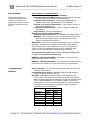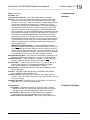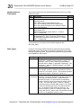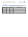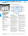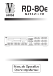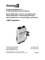
1
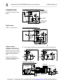
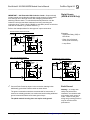
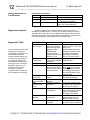
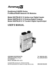
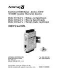
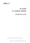
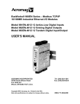
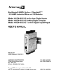
BusWorks® 900PB Series ProfiBus/RS485 Network I/O Modules Model 981PB-2012 12 Active-Low Digital Inputs Model 982PB-2012 12 Sinking Digital Outputs Model 983PB-2012 12 Tandem Digital Input/Output USER’S MANUAL ACROMAG INCORPORATED 30765 South Wixom Road Wixom, MI 48393-2417 U.S.A. Copyright 2002, Acromag, Inc., Printed in the USA. Data and specifications are subject to change without notice. Tel: (248) 624-1541 Fax: (248) 624-9234 8500689E 2 BusWorks® 981/982/983PB Module User’s Manual ProfiBus Digital I/O __________________________________________________________________ TABLE OF CONTENTS Symbols on equipment: ! Means “Refer to User’s Manual (this manual) for additional information”. The information of this manual may change without notice. Acromag makes no warranty of any kind with regard to this material, including, but not limited to, the implied warranties of merchantability and fitness for a particular purpose. Further, Acromag assumes no responsibility for any errors that may appear in this manual and makes no commitment to update, or keep current, the information contained in this manual. No part of this manual may be copied or reproduced in any form without the prior written consent of Acromag, Inc. IMPORTANT SAFETY CONSIDERATIONS You must consider the possible negative effects of power, wiring, component, sensor, or software failure in the design of any type of control or monitoring system. This is very important where property loss or human life is involved. It is important that you perform satisfactory overall system design and it is agreed between you and Acromag, that this is your responsibility. GETTING STARTED MOUNTING AND DIMENSIONS……………………… CONTROLS & INDICATORS..………………………… ISOLATION BARRIERS..………………………………. SETTING SLAVE ADDRESS………………………….. I/O PULLUP RESISTOR INSTALLATION…………… CONNECTIONS…………………………………………. DIN-Rail Mounting And Removal……………… Network…………………………………………….. Power……………………………………………….. Digital Inputs……………………………………… Digital Outputs..………………………………….. Earth Ground..……………………………………. TROUBLESHOOTING………………………………….. Tips For Building ProfiBus Networks..………. Top Four Common ProfiBus Problems………. Troubleshooting Tools………………………….. Using Connectors To Troubleshoot………….. Diagnostics Function……………………………. Diagnostics Table………………………………. 3 3 3 4 4 5 5 5 7 7 8 9 10 10 11 11 11 12 12 TECHNICAL REFERENCE KEY FEATURES………………………………………… HOW IT WORKS………….…………………………….. SPECIFICATIONS………………………………………. Model Numbers….……………………………….. Digital Inputs…………………....………………… Digital Outputs………………..………………….. General Specifications………………………….. Enclosure and Physical…………………………. Agency Approvals…..……………………………. Environmental…………………………………….. Communication Interface……………………….. Controls & Indicators……………………………. Module Specific Parameters…………………… Data Types………………………………………… 13 14 15 15 15 15 16 16 17 17 18 19 19 20 Windows® is a registered trademark of Microsoft Corporation. Profibus® is a registered trademark of ProfiBus Trade Organization. All trademarks are the property of their respective owners. ______________________________________________________________________________________ Acromag, Inc. Tel:248-624-1541 Fax:248-624-9234 Email:[email protected] http://www.acromag.com TB4 TB3 MOUNTING AND DIMENSIONS Unit mounts to “T” type DIN rails (35mm, type EN50022). DIGITAL IN or OUT DC- PWR Units may be mounted sideby-side on 1-inch centers. Model 983PB-2012 Shown (981PB-2012 & 982PB-2012 Similar) WARNING: IEC Safety Standards may require that this device be mounted within an approved metal enclosure or sub-system, particularly for applications with exposure to voltages greater than or equal to 75VDC or 50VAC. RTN CH 6 CH 7 CH 5 TB2 11 12 13 14 15 16 CH 4 DIGITAL IN or OUT RTN CH 2 CH 1 CH 3 CH 0 EXC1 TB1 2.34 (59.4) DIGITAL IN or OUT 21 22 23 24 25 26 TB2 TB1 1.05 (26.7) DC+ CH 8 EXC3 CH 9 CH10 RTN LSD MSD 33 32 31 SLAVE ADDRESS (HEX) EXC2 8 9 10 11 PROFIBUS CH11 4.68 (118.9) 01 23 4 567 3.75 (95.3) CH. I/O STATUS CL 46 45 44 43 42 41 BUS TB4 Acromag RUN 3.90 (99.1) "T" RAIL DIN MOUNTING DIN EN 50022, 35mm 4.35 (110.5) NOTE: Dimensions Are INCHES (MILLIMETERS). 3 TB3 BusWorks® 981/982/983PB Module User’s Manual ProfiBus Digital I/O ___________________________________________________________________ MODEL 981/982/983PB ENCLOSURE DIMENSIONS DP SLAVE ADDRESS SWITCHES TB4 D IGITA L IN or OU T CONTROLS & INDICATORS Green Run LED will stay ON if power is on and unit is OK, and will blink if unit fails. TB3 SLA VE A D D RESS (H EX) DC+ DC- LSD MSD 33 32 31 TB4 EXC3 CH 8 CH 9 01 23 4 567 46 45 44 43 42 41 I/O LED's (YELLOW) ON WHEN OUTPUTS ARE CONDUCTING OR INPUTS ARE ASSERTED LOW. CH10 BUS RTN PWR 8 9 10 11 PROFIBUS Yellow BUS LED will turn ON if module is connected to the network and in data exchange mode. Model 983PB-2012 Shown (981PB-2012 & 982PB-2012 Similar) 11 12 13 14 15 16 RTN CH 7 CH 6 CH 5 Yellow I/O LED’s will turn ON if output switch is closed, or input signal is asserted low. 21 22 23 24 25 26 TB2 TB1 981/982/983PB ISOLATION DIAGRAM CH 4 TB2 RTN CH 2 CH 1 CH 3 CH 0 TB1 D IGITA L IN or OU T DIGITAL I/O PWR TB4 SLAVE ADDRESS (HEX) DIGITAL IN or OUT DC+ LSD MSD 33 32 31 PWR TRANSFORMER OPTICAL 5V 11 12 13 14 15 16 ISOLATION BARRIERS Dashed Lines denote isolation barriers. The I/O circuit, network, and power circuit are isolated from each other for safety and noise immunity. RTN CH 7 CH 6 CH 5 CH 4 DIGITAL IN or OUT TB2 RTN CH 2 CH 3 CH 1 CH 0 EXC1 TB1 DIGITAL IN or OUT EXC2 NETWORK 5V TB3 TB4 EXC3 CH 8 CH 9 CH10 RTN CH11 46 45 44 43 42 41 TB3 DC- REMOVABLE (PLUG-IN TYPE) TERMINAL BLOCKS EXC1 D IGITA L IN or OU T PROFIBUS CONNECTOR DB9 FEMALE EXC2 CH. I/O STATUS RUN RUN/PWR LED (GREEN) BUS STATUS LED (YELLOW) CH11 Acromag TB3 21 22 23 24 25 26 TB2 TB1 DIGITAL I/O DIGITAL I/O Acromag, Inc. Tel:248-624-1541 Fax:248-624-9234 Email:[email protected] http://www.acromag.com 4 BusWorks® 981/982/983PB Module User’s Manual ProfiBus Digital I/O __________________________________________________________________ HEX ADDRESS MSD LSD x16 x1 SETTING SLAVE ADDRESS TOP EDGE VIEW Address is set to 126 (7EH) from factory. This address is reserved for commissioning purposes only. EF 0 1 2 EF 0 1 2 D 3 D 3 C 4 C 4 B 5 B 5 A9 76 A9 76 8 8 SET SWIT CHES T O A VALID SLAVE ADDRESS FROM 0 TO 125 (00H TO 7DH) Locate hexadecimal address switches in recessed opening next to power terminals. 1. Choose a slave address from 0-125 and locate highest MSD number less than this address. Set MSD switch to this number's corresponding HEX digit. Use a screwdriver to rotate these switches to set a unique valid address from 0 to 125. If these switches are instead set to 126 (7EH) upon powerup (or 126 to 254), the unit will retrieve its address from the internal EEPROM, which is modified via the Set Slave Address command. If these switches are set to 255 (FFH) upon power-up, this will return the address in EEPROM to 126 (7EH). I/O PULLUP RESISTOR INSTALLATION 5.6KΩ I/O Pullup resistors are already installed from the factory. You do not need to refer to this information unless you need to change or remove these resistors. You must connect excitation and/or install pull-ups for proper operation. I/O terminals must not be left floating. 2 0 0 0 0 16 1 1 1 32 2 2 2 48 3 3 3 64 4 4 4 80 5 5 5 96 6 6 6 112 128 144 160 176 192 208 224 240 7 8 9 A B C D E F 7 8 9 10 11 12 13 14 15 7 8 9 A B C D E F 2. Determine the DECimal remainder and set the LSD switch to its corresponding HEX digit. The address stored in the internal EEPROM is modified via the Set Slave Address command. If the address switches are set to 126 (or 126 to 254) upon power-up, the module will retrieve the last address stored within its EEPROM (126 from the factory). With both the internal EEPROM and external switch addresses set to 126, the unit will await the Set Slave Address command after power-up, before proceeding to the parameterization state (address 126 cannot be used in data exchange mode and is reserved for commissioning purpose only). You must use the Set Slave Address command to change the internal (EEPROM) address following power-up in order to proceed. However, if the switches are set to an address less than 126 upon power-up, then the switches determine the slave address and the EEPROM setting is ignored. You can later restore the internal EEPROM setting to 126 by powering the unit up with the address switches set to 255 (FF). You would then power the unit up again with these switches set to 126 in order to place the unit in commissioning mode. PORT 2 RTN (CH8-11) EXC+ 5.6K x4 ISOLATED 0.5W RESISTORS RESISTOR NETWORK Acromag RUN CH. I/O STATUS If the switches are set to a valid address from 0-125, then the switch setting determines the slave address and the Set Slave Address command will be rejected. MSD x16 HEX LSD DEC x1 HEX 1 BUS 01 23 4 567 8 9 10 11 PROFIBUS BOURNS 4308H-102-562 OR EQUIVALENT SERIES 981PB/982PB/983PB SIP PULLUP RESISTOR SOCKET LOCATION TB4 TB3 SOCKET PORT 2 CH11 CH10 CH9 CH8 X3 EACH PORT HAS A SIP RESISTOR LOCATED AS SHOWN AT RIGHT. SIP RESISTORS PULL-UP THE I/O CHANNEL TO THE EXC SUPPLY. 8 7 6 5 4 3 2 1 R11 BASE BOARD PLUG-IN I/O BOARD (Turned Face Up) SIPS ARE INSTALLED IN SOCKETS X1, X2, AND X3. PORT 0 SIP = R2 INSTALLED IN X1 PORT 1 SIP = R7 INSTALLED IN X2 PORT 2 SIP = R11 INSTALLED IN X3 THE SIP IS AN ISOLATED RESISTOR NETWORK OF 4 ELEMENTS. FACTORY SIP VALUE IS 5.6K OHMS. POWER IS 0.5W PER ELEMENT. PORT 1 WHEN REPLACING SIPS OR CHANGING VALUES, WATCH THAT POWER DISSIPATION DOES NOT EXCEED SIP RATING. USE SMALL SCREW DRIVER TO PRY OFF SIDE COVER. COVER IS HELD IN PLACE WITH EIGHT SNAP PINS. CAREFULLY SEPARATE I/O BOARD FROM BASE BOARD. CAUTION: HANDLE CIRCUIT USING ESD-SAFE PROCEDURES. PORT 0 CH7CH6CH5CH4 X2 THE EVEN-NUMBERED PINS OF THE SOCKETS ARE TIED TO THE PORT EXCITATION TERMINAL. EXC+ PORT 0 RTN (CH0-3) 1 2 3 4 5 6 7 8 R7 R2 PULLUPS ARE LOCATED IN SOCKETS ON PLUG-IN I/O BOARD AS SHOWN HERE TB2 TB1 CH3CH2CH1CH0 X1 1 2 3 4 5 6 7 8 EXC+ PORT 1 (CH4-7) 981PB/982PB/983PB SHOWN WITH SIDE COVER REMOVED AND I/O BOARD SEPARATED RTN WHEN REPLACING COVER, ALIGN ALL PINS, THEN SNAP TOGETHER IN SEQUENCE TO SECURE COVER. ______________________________________________________________________________________ Acromag, Inc. Tel:248-624-1541 Fax:248-624-9234 Email:[email protected] http://www.acromag.com BusWorks® 981/982/983PB Module User’s Manual ProfiBus Digital I/O ___________________________________________________________________ To Remove or Replace Factory Pullup Resistors… Locate pullup resistor SIP’s installed in sockets of plug-in I/O board as shown above. You must remove the side cover and separate the two boards to remove or install these resistors. 5.6K resistor SIP’s are installed from the factory. Remove these resistors if I/O channels are pulled up externally. Limit power in each SIP resistor to 0.4W maximum. 5 If your application delivers power to the I/O terminals rather than the excitation terminal, the internal pull-ups should be removed to avoid coupling current into adjacent port channels. CONNECTIONS PUSH MODULE REMOVAL FROM DIN RAIL DC- DC+ LSD MSD 33 32 31 SLAVE ADDRESS (HEX) DIN-Rail Mounting & Removal TB3 TB4 USE YOUR FINGER TO APPLY DOWNWARD PRESSURE HERE AS YOU LIFT AND TILT MODULE TO REMOVE IT FROM RAIL 46 45 44 43 42 41 PWR "T" TYPE DIN RAIL TB2 Any Series 9XXPB ProfiBus Module TB1 When attaching the module to the T-type DIN rail, angle the top of the unit towards the rail and locate the top groove of the adapter over the upper lip of the rail. Firmly push the unit towards the rail until it snaps into place. To remove, first separate the input terminal block(s) from the bottom side of the module to create a clearance to the DIN mounting area. Next, while holding the module in place from above, insert a screwdriver into the lower arm of the DIN rail connector and use it as a lever to force the connector down until the unit disengages from the rail (do not twist the screwdriver to avoid damaging plastic). 11 12 13 14 15 16 21 22 23 24 25 26 Remove Terminal Blocks On This Side To Provide Clearance PRY WITH SCREWDRIVER INSERTED IN SLOT HERE (DO NOT TWIST TO AVOID DAMAGING PLASTIC TAB) PUSH SCREWDRIVER AS SHOWN TO TILT AND LIFT MODULE OFF RAIL 8 3 7 off R on off ProfiBus Cable (Violet) Green Wire = A Red Wire = B IN OUT Network Do not mix RS485 A & B connections. Green wire is A, red wire is B. You MUST terminate the network at both ends only. Termination resistors are integrated in the ProfiBus connector. When you switch termination ON, the out-going connections are disconnected from the network. Insul Shld on Grn Termination Switch Strip Cable Similar to Shown AB 0.25 Red 2 6 1 DB9 (Male) 4 9 5 Siemens ProfiBus Connector Network Use ProfiBus connectors similar to the one shown at left (Siemens version shown). 0.35 0.30 PVC Sheath Use ProfiBus cable per DIN 19245 and EN 50170. Always use ProfiBus cable per DIN 19245 and EN 50170. When building cables, do not mix A & B connections. Green wire is A, Red wire is B. The connector must have built in inductors in order to operate at the higher baud rates. Acromag, Inc. Tel:248-624-1541 Fax:248-624-9234 Email:[email protected] http://www.acromag.com 6 BusWorks® 981/982/983PB Module User’s Manual ProfiBus Digital I/O __________________________________________________________________ CONNECTIONS Network GSD Files: 981PB-2012 ACRO06F3.GSD Ident_Number=06F3H 982PB-2012 ACRO06F2.GSD Ident_Number=06F2H 983PB-2012 ACRO06F1.GSD Ident_Number=06F1H Network Length IMPORTANT: Do not connect earth ground to logic Ground (DB9 Pin 5). Earth Ground should connect to Shield (Common to DB9 Pin 1). Note that Acromag modules also support the optional RTS direction control signal at Pin 4. Use Type A ProfiBus cable per EN 50170. Keep line lengths less than the length indicated below for your transmission rate. For baud rates not shown, the lower length of the closest range end points apply (i.e. 100M at 3MB). Bus Segment Length Limit Per Baud Rate For Type A Bus Cable BAUD 9.6K 19.2K 93.75K 187.5K 500K 1.5MB 12MB Type A 1200M 1200M 1200M 1000M 400M 200M 100M Termination The network must be terminated at both ends only. Most ProfiBus connectors include a switch for termination as shown above. Note that this switch will also disconnect the outgoing network signal. Example ProfiBus System Connections Up to 125 slave modules may network together with a class 1 master using four repeaters (one repeater every 31 nodes). Address 0 is typically reserved for the class 1 master. Note: 12Mbps installations require a minimum cable length of 1M between stations. TIP: A recommended RS485 repeater for ProfiBus is the Siemens 6ES7 972-0AA010XA0. A network segment may contain up to 32 nodes without the use of a signal repeater. Transmission distance is up to 1200 meters per segment without a repeater. Termination must be placed at both ends of a network or network-segment. A cr om ag A cr om ag RUN RUN BUS PRO FI BUS BUS The total number of nodes and total distance may be extended by using signal repeater(s). The maximum number of modules possible is further limited by the address range from 0 to 125. PRO FI BUS on 61 of f A cr om ag RUN RUN PRO FI BUS on 31 BUS BUS PRO FI BUS RS485 SIGNAL REPEATER TERMINATION SWITCH NODE 32' A cr om ag on of f NODE 2' END OF NETWORK (TERMINATION ON) NODE 1' START OF SEGMENT (TERMINATION ON) on of f NODE 32 30 NODE 31 END OF SEGMENT (TERMINATION ON) of f 4 NODE 5 SEGMENT 2 (UP TO 1200 METERS, UP TO 32 NODES PER SEGMENT) PROFIBUS MASTER PLUG-IN CARD INSTALLED IN PC. NETWORK LENGTH PER BAUD RATE w/ TYPE A PROFIBUS CABLE BAUD 9600bps 19.2Kbps 93.75Kbps 187.5Kbps 500Kbps 1.5Mbps 12Mbps LENGTH 1200M 1200M 1200M 1000M 400M 200M 100M START OF NETWORK (TERMINATION REQD) PROFIBUS MASTER - A HOST PC WITH PROFIBUS CARD INSTALLED AND RUNNING APPLICATION SOFTWARE. A cr om ag A cr om ag RUN RUN RUN BUS PRO FI BUS on of f 2 NODE 3 BUS PRO FI BUS on of f 1 BUS PRO FI BUS on NODE 1 NODE 2 PROFIBUS RS485 NETWORK A cr om ag of f 3 NODE 4 SEGMENT 1 (UP TO 1200 METERS, UP TO 32 NODES PER SEGMENT) NOTE: THE PROFIBUS CONNECTORS SHOWN HAVE A TERMINATION NETWORK BUILT-IN. WITH TERMINATION ON, THE OUTGOING CABLE IS DISCONNECTED FROM NETWORK. SWITCH TERMINATION ON ONLY AT THE BEGINNING AND END OF A NETWORK OR NETWORK SEGMENT. ______________________________________________________________________________________ Acromag, Inc. Tel:248-624-1541 Fax:248-624-9234 Email:[email protected] http://www.acromag.com BusWorks® 981/982/983PB Module User’s Manual ProfiBus Digital I/O ___________________________________________________________________ Connect 12-36V DC to the power terminals labeled DC+ & DC-. Observe proper polarity. For supply connections, use No. 14 AWG wires rated for at least 75C. CAUTION: Do not exceed 36VDC peak. TB3 NC EARTH GROUND DC- PWR TB3 DC+ INPUT POWER IS ISOLATED IMPORTANT – External Fuse: If unit is powered from a supply capable of delivering more than 1A to the unit, it is recommended that this current be limited via a high surge tolerant fuse rated for a maximum current of 1A or less (for example, see Bel Fuse MJS1). Connect digital input signals to the input terminals. Refer to the figures below: 5.6K SIP RESISTOR INSTALLED IN SOCKET I/O +5V OFF (0) 100K OFF (0) R TVS (48V) ON (1) TVS (48V) ON (1) (Active-LOW) CH LED RTN R OFF (0) CH LED Digital Inputs (981PB & 983PB Only) 983PB SIMPLIFIED INTERNAL I/O CONNECTIONS (ONE CHANNEL) SHIELDED CABLE OR OPEN COLLECTOR OR DRAIN TB1 EXC CH00 CH01 CH02 CH03 RTN +5V DIGITAL IN or OUT 16 15 14 13 12 11 DIGITAL INPUT CONNECTIONS +5V Input threshold is TTL compatible. Limit Input Voltages to 35V maximum. RTN LOW-SIDE SWITCH CAUTION: Risk of Electric Shock – More than one disconnect switch may be required to de-energize equipment before servicing. Inputs are active-low. TO OTHER 3 CHAN OF PORT OFF (0) 100K ON (1) (Active-LOW) Current 224mA 170mA 104mA 74mA ON (1) TO OTHER 3 CHAN OF PORT OFF (0) 5.6K SIP RESISTOR INSTALLED IN SOCKET EXC +5V ON (1) I/O Power SIMPLIFIED 983PB CHANNEL (Tandem Input/Output) SIMPLIFIED 981PB CHANNEL (Input Only) EXC CONNECTIONS Voltage 12VDC 15VDC 24VDC 36VDC SLAVE ADDRESS (HEX) 12 TO 36VDC LSD MSD 33 32 31 7 5.6K PULLUP (IN SOCKET) 100K Note: Do not allow EXC or unused inputs to float. If pullups are installed, this will cause one I/O signal to pull the other floating port channels via the pull-ups and common EXC lead connection. TB1 Refer to the examples below for other types of input connections. DRY-CONTACT RELAY CONNECTIONS - NORMALLY OPEN 981PB & 983PB I EXC SIP INSTALLED +5V 5.6K ADJUST VOLTAGE (V) AS REQUIRED TO CHANGE EXCITATION CURRENT( I) OR CHANGE SIP RESISTOR VALUE. Normally Open Dry Contact Relay. OTHER THREE CHAN OF PORT 100K V I/O N.O. RTN R 983PB ONLY CH CH LED IS ON FOR ACTIVE-LOW INPUT ON 983PB UNITS, MAKE SURE OUTPUT IS OFF (0) FOR INPUT ONLY APPLICATIONS. Acromag, Inc. Tel:248-624-1541 Fax:248-624-9234 Email:[email protected] http://www.acromag.com 8 BusWorks® 981/982/983PB Module User’s Manual ProfiBus Digital I/O __________________________________________________________________ CONNECTIONS DRY-CONTACT RELAY CONNECTIONS - NORMALLY CLOSED EXC Normally Closed Dry Contact Relay. N.C. 981PB & 983PB +5V SIP INSTALLED 5.6K ADJUST VOLTAGE (V) AS REQUIRED TO CHANGE EXCITATION CURRENT( I) OR CHANGE SIP RESISTOR VALUE. OTHER THREE CHAN OF PORT 100K V I/O R 983PB ONLY CH LED IS ON FOR ACTIVE-LOW INPUT CH ON 983PB UNITS, MAKE SURE OUTPUT IS OFF (0) FOR INPUT ONLY APPLICATIONS. RTN Digital Inputs Digital TTL Logic Monitor LOGIC (TTL) MONITOR (981PB & 983PB ONLY) EXC 981PB or 983PB 5.6K SIP RESISTOR INSTALLED IN SOCKET ON +5V ON TO OTHER 3 CHAN OF PORT 100K RLIM OFF OFF 5V I/O R RLIM IS INCLUDED TO PROTECT DRIVER IF TANDEM OUTPUT IS INADVERTANTLY TURNED ON. 983PB CH ON OFF RTN ON 983PB, KEEP OUTPUTS TURNED OFF TO MONITOR EXTERNAL LOGIC SIGNAL Digital Outputs (982PB & 983PB Only) Connect digital outputs to the output terminals. Refer to figures below: SIMPLIFIED 983PB CHANNEL (Tandem Input/Output) SIMPLIFIED 982PB CHANNEL (Output Only) Outputs are the open-drains of DMOS mosfet switches for DC current-sinking applications only. Outputs turn OFF (open) following a software or poweron reset of the module. 5.6K SIP RESISTOR INSTALLED IN SOCKET EXC 5.6K SIP RESISTOR INSTALLED IN SOCKET EXC +5V ON (1) I/O TO OTHER 3 CHAN OF PORT I/O ON (1) TVS (48V) ON (1) (Active-LOW) OFF (0) 100K OFF (0) OFF (0) TO OTHER 3 CHAN OF PORT OFF (0) ON (1) (Active-LOW) R CH LED ON (1) TVS (48V) R CH LED OFF (0) RTN RTN DIGITAL OUTPUT CONNECTIONS POSSIBLE VARIATIONS - CURRENT SINKING DC APPLICATIONS ONLY INTERNAL OUTPUT PULLUPS ARE OPEN OUTPUTS RATED TO 35V/500mA DC R D L OUT0 0-35V OUT1 D L V A 983PB SIMPLIFIED INTERNAL I/O CONNECTIONS (ONE CHANNEL) SHIELDED CABLE R OUT2 0-V B FOR GREATER OUTPUT DRIVE, CONNECT AN INTERPOSING RELAY (+) OUT3 (-) TB1 EXC CH00 CH01 CH02 CH03 RTN +5V DIGITAL IN or OUT 0-35V 16 15 14 13 12 11 V B 5.6K PULLUP (IN SOCKET) 100K TB1 OPEN-DRAIN OUTPUTS SHARE RETURN EARTH GROUND ______________________________________________________________________________________ Acromag, Inc. Tel:248-624-1541 Fax:248-624-9234 Email:[email protected] http://www.acromag.com BusWorks® 981/982/983PB Module User’s Manual ProfiBus Digital I/O ___________________________________________________________________ IMPORTANT – Add Protection With Inductive Loads: Outputs already include internal reverse-bias shunt diodes to help protect the output switch from damage due to the high reverse-bias voltages generated when switching inductive loads. You should add external protection near the inductive load to prevent these transients from being sent along the connection wires. Place a diode (1N4006 or equivalent) across an inductive load with the cathode to (+) and the anode to (-). 9 Digital Ouputs (982PB & 983PB Only) Refer to the examples below for other types of output connections. SOLID-STATE RELAY (SSR) OR LED DRIVER TO LOAD/LINE EXC 5.6K SIP RESISTOR INSTALLED IN SOCKET R SSR (N.O.) LED Examples: - Solid-State Relay (SSR) or LED Driver. 983PB +5V - Relay Coil or Solenoid Driver (Note Protection). ON TO OTHER 3 CHAN OF PORT 100K OFF V I/O TO LOAD/LINE - Lamp Driver. R 982PB/983PB CH ON OFF RTN RELAY COIL/SOLENOID DRIVER INCANDESCENT LAMP CONTROL EXC 983PB 5.6K SIP RESISTOR INSTALLED IN SOCKET 1N4006 TO OTHER 3 CHAN OF PORT +5V ON 100K I/O ON TO OTHER 3 CHAN OF PORT 100K OFF R 982PB/983PB V 5-35V I/O CH OFF R 982PB/983PB ON CH ON OFF RTN 983PB 5.6K SIP RESISTOR INSTALLED IN SOCKET +5V V 5-35V EXC Connect Earth Ground as shown in the connection drawing below. Additionally, ground the ProfiBus cable as shown below. The ground connections noted are recommended for best results. If sensors are already grounded, use caution and avoid making additional ground connections which could create ground loops. The plastic module housing does not require earth ground. OFF RTN Earth Ground Warning: To comply with safety and performance standards, use shielded cable and connect earth ground as noted. Failure to use good wiring and grounding practices may be unsafe and hurt performance. Acromag, Inc. Tel:248-624-1541 Fax:248-624-9234 Email:[email protected] http://www.acromag.com 10 BusWorks® 981/982/983PB Module User’s Manual ProfiBus Digital I/O __________________________________________________________________ CONNECTIONS PROFIBUS WIRING AND GROUND PROFIBUS CONNECTOR GROUNDING: 1. Always connect the cable shield to earth ground at both ends as shown. 2. If the field device does not include an earth ground screw, it may be necessary to strip the cable insulation near the field device and clamp the cable shield to a local grounding bar or surface as shown. PROFIBUS FIELD DEVICE THE SHIELD IS COMMON TO THE HOUSING (FOR METAL ENCLOSURES). OUT R on off CABLE SHIELD ACROMAG MODULES: Tips For Building ProfiBus Networks CABLE SHIELD EQUIPOTENTIAL BONDING STRIP (IF NECESSARY--SEE NOTE) The metal shroud of the DB9 ProfiBus connector on Acromag modules is common to pin 1 of the DB9 connector (SHIELD). This is also common to the cable shield which must be earth grounded. Acromag modules are enclosed in plastic and do not provide a dedicated earth ground screw. As such, a local earth ground connection to the cable shield must be made as shown above. TROUBLESHOOTING INP NOTE: If a potential difference exists between earth grounding points, an equalization current can flow through the cable shield when connected at both ends. In this case, it may be necessary to install an additional potential equalization line between field locations to minimize this current as shown here. GROUND CLAMP EARTH GROUND SCREW ON EQUIPMENT (WHEN AVAILABLE) PROFIBUS CABLE GROUND CLAMP THE SHIELD IS COMMON TO THE HOUSING (FOR METAL ENCLOSURES). Use ProfiBus cable per DIN 19245 and EN 50170. Use only approved cables with braided shields of density greater than 80%. Green Wire = A Red Wire = B AB Shld Red R on off EARTH GROUND SCREW ON EQUIPMENT (WHEN AVAILABLE) Grn PROFIBUS FIELD DEVICE Insul PROFIBUS CONNECTOR PVC Sheath The module routinely performs internal diagnostics following power-up or reset. During this period, the green “Run” LED will flash for a moment. If the diagnostics complete OK, the “Run” LED will stop flashing after a few seconds and remain ON. This indicates the unit is operating normally. Once the unit has passed through the initialization, parameterization, and configuration states, and is in data exchange mode, the yellow BUS LED will be ON. If the BUS LED is OFF and the unit is connected to the network, then this is indicative of an initialization problem. Follow the ProfiBus installation guidelines. Use the recommended cable and connectors of the standard. Verify that none of the wires are broken or shorted. Don’t mix the A & B lines. Use green wire for A and red wire for B. Do not exceed the recommended segment length for the baud rate. Make sure that there are no more than 32 RS-485 devices per segment (including the master device and the repeater). Check for proper termination of all copper-wire network segments (an RS-485 segment must have a termination resistor at both ends of the segment only). All activated terminations must be powered all the time. If this is not possible, then consider using an active-termination box. Check whether the station address is set to the correct value. If your network connects between buildings or runs through hazardous environments, consider the use of fiber-optics. Avoid drop lines and keep their length within the specified maximum. For T-drops, consider using repeaters and active-bus terminations. ______________________________________________________________________________________ Acromag, Inc. Tel:248-624-1541 Fax:248-624-9234 Email:[email protected] http://www.acromag.com BusWorks® 981/982/983PB Module User’s Manual ProfiBus Digital I/O ___________________________________________________________________ 1. Incorrect slave address set at the slave. 2. ProfiBus connector between the master and slave has its termination switch turned ON. 3. Incorrect module configuration sent to slave. 4. Configuration is based on outdated GSD file information. There are several models of handheld devices on the market that simplify the installation and troubleshooting of ProfiBus networks. The more sophisticated units include LCD displays that read out errors directly. Two of these of these devices are referenced below: 11 Top Four Common ProfiBus Problems Troubleshooting Tools Hand-Held ProfiBus Network Maintenance Tools Manufacturer Part Number Special Features Siemens BT 200 Primarily a Cable Tester Comsoft NetTest II Set Includes DP Mono-Master 4000-7-06C-J Functionality In general, these devices can be used to check the network wiring before devices are connected to the bus and are often used to indicate: Whether the A and B lines have been switched. Whether a short exists between the A & B lines and shield. The occurrence of a wire-break in the A or B line, or shield line. Improper termination. These devices can also be used to check the RS-485 interface of ProfiBus devices after they have been connected. They may include the following functions: Create a list of all stations connected to a network (useful for identifying missing or “offline” devices). Test individual stations and help identify duplicate addresses. Measure the distance along a network segment to verify whether it complies with Profibus requirements for distance and data rate. Detect signal reflections along the network, useful for locating bus line interruptions and discontinuities. Acromag strongly suggests the use of these tools for building and maintaining ProfiBus networks. Note that Profichip also offers a Profibus connector (PA003100) that includes 4 network diagnostic LED’s that may be helpful in trouble-shooting your network (see table below). The standard 9-pin ProfiBus connectors with integrated termination resistors are also helpful in troubleshooting segments of the network. In most of these connectors, when the termination resistors are switched ON, the outgoing portion of the connector is disconnected. As such, you can selectively disable segments of the network until you find the branch that is causing the problem. For example, if your handheld unit is connected to the beginning of a network and indicates a wire break, you can selectively switch off portions of the network and recheck your handheld unit to help pin point the portion of the network that is causing the problem. Below are some ProfiBus connectors that we recommend: Using Connectors To Troubleshoot Acromag, Inc. Tel:248-624-1541 Fax:248-624-9234 Email:[email protected] http://www.acromag.com 12 BusWorks® 981/982/983PB Module User’s Manual ProfiBus Digital I/O __________________________________________________________________ Using Connectors To Troubleshoot Preferred Bus Connectors Manuf. Part Number Siemens 6ES7972-0BA12-0XA0 Siemens 6ES7972-0BB12-0XA0 Profichip Diagnostics Function Diagnostics Table If your problem still exists after checking your wiring and reviewing this information, or if other evidence points to another problem with the unit, an effective and convenient fault diagnosis method is to exchange the module with a known good unit. Acromag’s Application Engineers can provide further technical assistance if required. Complete repair services are also available from Acromag. PA003100 Special Features Switchable Termination Adds PB Interface (Piggy Back DB9 For Diagnostic Connection) Adds PB Interface and 4 Diagnostic LED’s For Trouble-Shooting. ProfiBus includes a rich diagnostic function that can be used to troubleshoot ProfiBus devices. This function contains 6 bytes of standard diagnostic information, plus up to an additional 238 bytes of device specific diagnostic information. Most configuration tools support this command and can read the diagnostic information from the Profibus device. SYMPTOM Yellow BUS LED does not light. Cannot communicate. Yellow BUS LED turned OFF. Continuous flashing green RUN LED. Many Communication Errors. POSSIBLE CAUSE Initialization Problem. LED ON if module in data exchange state. Both the internal EEPROM and external address switches are set to an address of 126. Power ON at the module and/or RS485 converter? Is address correct? Is the termination switch of the Profibus connector at the prior node turned on? Communication Halted. Internal firmware problem. Missing Termination Resistors? Is baud rate too high for distance? Outputs Not Working. Missing excitation connection? Missing pull-up resistors? POSSIBLE FIX Check Station Address. Is GSD file correct. Check for wiring error. Module awaiting Set Slave Address command in order to complete initialization. Alternately, set switches from 0-125 and re-power. Check power. Is green RUN LED ON? Check slave address setting Switch Termination on only at the ends of the network. With termination switch on, the outgoing connections are disconnected from the network chain. Cycle power to reset unit. Investigate grounding. Return module for service. Termination resistors must be placed only at both ends of a network or segment. Maximum distance is limited below 1200 meters as baud rate is increased above 93.75Kbps (see Table). Connect an excitation supply between the port EXC and RTN terminals Install SIP resistor in socket on board for port of interest. ______________________________________________________________________________________ Acromag, Inc. Tel:248-624-1541 Fax:248-624-9234 Email:[email protected] http://www.acromag.com BusWorks® 981/982/983PB Module User’s Manual ProfiBus Digital I/O ___________________________________________________________________ 13 TECHNICAL REFERENCE PTO Certified - Certified by the ProfiBus Trade Organization. Safety Agency Approvals – CE, UL, & cUL listed, plus Class 1; Division 2; Groups A, B, C, D approval. Fully Independent Slave w/ Direct I/O Connection – Self-contained unit does not require special bus couplers, power supply, or rack mount to operate. Plug-In Terminal Blocks & DIN-Rail Mount - Make mounting, removal, and replacement easy. Industry Standard ASIC – Siemens SPC3 intelligent ASIC for ProfiBus. Isolated RS485/ProfiBus Network Interface – Immune to noise & can operate over long distances. Allows many modules to network together. Auto-Baud Rate Detection – The baud rate is set automatically. High-Speed Data Rates – Half-duplex RS485 up to 12M baud. Includes RTS Support – ProfiBus interface includes the optional RTS (Request-To-Send) direction control. Failsafe Mode Support – Slave outputs can be sent to a failsafe state if the slave master fails. Supports Set_Slave_Address Command – Allows unit to have its address set via software. Supports Sync & Freeze – Useful for synchronization of output control. Nonvolatile Reprogrammable Memory – Allows the functionality of this device to be reliably reprogrammed thousands of times. Fully Isolated – I/O channels, network, and power are all isolated from each other for safety and increased noise immunity. Flexible Discrete Inputs and Outputs - High voltage & current opendrain outputs provide direct (low-side) control of external devices. Buffered inputs allow outputs to be read back, or input levels to be monitored. Tandem Input/Output Circuitry (983PB Only) - Input buffers are connected in tandem with open-drain outputs for convenient loop-back monitoring of the output state. Convenient Pullup Resistors Mounted In Sockets – SIP resistors are installed in sockets on the I/O board and provide input and output pullups to the excitation supply. These SIP resistors can be easily removed or exchanged according to your application. Outputs Have Built-in Protection – Over-temperature and over-current shut-down protection is built-in and outputs include active clamping circuitry for switching inductive loads. LED Indicators – Yellow LED’s indicate I/O state (active-low). Green LED indicates power. Yellow BUS LED indicates data exchange mode. Watchdog Timer Built-In – Standard for the ASIC and operates in the data exchange mode if communication with the master is lost. Self-Diagnostics & Built In Watchdog - For easy maintenance and troubleshooting. Includes a hardware watchdog timer built into the microcontroller that causes it to initiate a self reset if the controller ever “locks up” or fails to return from an operation in a timely manner. Wide-Range DC-Power – Wide range diode-coupled for use with redundant supplies, and/or battery back-up. Hardened For Harsh Environments - For protection from RFI, EMI, ESD, EFT, & surges. Has low radiated emissions per CE requirements. Wide Ambient Operation – Reliable over a wide temperature range. KEY FEATURES Acromag, Inc. Tel:248-624-1541 Fax:248-624-9234 Email:[email protected] http://www.acromag.com 14 BusWorks® 981/982/983PB Module User’s Manual ProfiBus Digital I/O __________________________________________________________________ These digital I/O modules will interface with any mix of up to twelve digital input and/or output signals according to the model, and provide an isolated RS485/ProfiBus interface for configuration, monitoring, and control of the I/O. Outputs of these models are the open-drains of n-channel mosfets (982PB & 983PB). Input buffers are connected in tandem with the drain circuits via series 100K resistors, and over-voltage clamps to +5V are connected to the buffer inputs (981PB & 983PB). I/O terminals also include transient suppression. Sockets are installed for installation of optional input or output drain pull-up resistors, and 5.6K SIP resistors are installed from the factory. These resistors are pulled up to an external supply connected to the EXC and RTN terminals. These modules implement the ProfiBus protocol via an industry-standard SPC3 ASIC from Siemens. This ASIC acts like a RAM or UART chip to the internal microcontroller and completely handles the requirements of the protocol standard. The ASIC communicates with the network via an optically isolated RS485 transceiver. It transfers network data to the microcontroller and automatically provides the response to the bus. The microcontroller completes the information transfer according to its I/O type and embedded program. I/O lines of the microcontroller switch outputs ON/OFF and sample the digital inputs. Embedded configuration parameters are stored in non-volatile memory integrated within the microcontroller. A wide input switching regulator (isolated flyback) provides isolated power to the I/O circuit and the RS485 port. Refer to the simplified schematic shown below to gain a better understanding of the circuit. HOW IT WORKS EXC 5.6K OHM SIP RESISTOR INSTALLED IN SOCKET 5.6K P U L L U P S 983PB SIMPLIFIED SCHEMATIC ISOLATED RS485 981PB/983PB INPUT BLOCK BUFFERED INPUT +5V TO OTHER 3 CHAN OF PORT RTS ON 100K OFF MICROCONTROLLER I/O Active LOW PROFIBUS SPC3 SLAVE ASIC RS485 PROFIBUS TRANSCEIVER RTN 4 DB9 SHLD 4 OPEN-DRAIN OUTPUT ADDRESS BUFFER ON OFF 982PB/983PB OUTPUT BLOCK SIMPLIFIED SCHEMATIC (1 CHANNEL OF 12) EF 0 1 2 D 3 C 4 B 5 A9 76 8 R (982PB) EF 0 1 2 D 3 C 4 B 5 A9 76 8 ISOLATED INPUT POWER or CH I/O STATUS LED R (981PB) (983PB) 12-36VDC ISOLATED SECONDARIES NETWORK POWER 5V I/O LOGIC POWER 5V ISOLATED FLYBACK SWITCHER DC+ DC- P O W E R ______________________________________________________________________________________ Acromag, Inc. Tel:248-624-1541 Fax:248-624-9234 Email:[email protected] http://www.acromag.com BusWorks® 981/982/983PB Module User’s Manual ProfiBus Digital I/O ___________________________________________________________________ 15 These DIN-rail mount, ProfiBus DP slave, digital I/O modules include twelve digital inputs (981PB), twelve digital outputs (982PB), or twelve combination digital input/output channels (983PB), and provide an isolated RS485/ProfiBus network interface. Units are DC-powered and include reverse polarity protection. Outputs are open-drain, low-side switches. Inputs are active-low. Channel I/O, network, and power are isolated. Outputs have high voltage and current capacity for discrete on/off control of external devices. Non-inverting, buffered inputs provide support for digital level sensing, or for simply reading back the tandem output (983PB). I/O channels share common. Pull-up resistors to the port EXC supply (every four channels) are installed in sockets on the board. Non-volatile reprogrammable memory in the module stores configuration information. SPECIFICATIONS The ProfiBus model prefix “900” denotes the Series 900. The “PB” suffix denotes ProfiBus. Select 981PB for digital inputs, 982PB for digital outputs, or 983PB for tandem digital inputs and outputs. The four digit suffix of this model number represents the following options, respectively: “2” = ProfiBus DP; “0” = Default; “12” = 12 Channels. Model Numbers 981PB-2012 (Input) 982PB-2012 (Output) 983PB-2012 (Inp/Out) Twelve active-low, buffered inputs, with a common connection (RTN). For DC voltage applications only. Inputs include transient suppression and have series connected 100K resistors, plus diode over-voltage clamps to the internal +5V supply. Sockets are provided at each port (group of four channels) for installation of SIP resistor networks that serve as pullups to the port EXC supply terminal. 5.6K pull-up resistor SIP’s are installed from the factory. External excitation is required for proper operation and is connected between the port EXC and RTN terminals. Digital Inputs (981PB & 983PB Only) Input Signal Voltage Range: 0 to +35VDC. Input Current: 293uA, typical at 35VDC. This is computed as the applied input voltage minus 5.7V, divided by the series 100K input resistance. Input Signal Threshold: TTL compatible with 100mV of hysteresis, typical. Low-to-High threshold is 1.7VDC typical, High-to-Low threshold is 1.6VDC, typical. Limit logic transition to TTL levels of 0.8VDC (Max LOW level) and 2.0VDC (Min HIGH level). Input Resistance: 100K, typical. Input Hysteresis: 100mVDC typical. Input Response Time: 800ns typical, measured from input step to logic transfer at the ASIC. Actual input response will vary with interrupts. Twelve open-drain, DMOS mosfet switches with a common source connection at the port RTN terminal. For DC voltage and current-sinking applications only. Outputs have built-in transient protection. Sockets are provided at each port (four channels) for quick replacement and installation of SIP resistor networks that serve as pullups to the port EXC supply terminal. 5.6K pull-up resistor SIP’s are installed from the factory. Digital Outputs (982PB & 983PB Only) Output “OFF” Voltage Range: 0 to 35V DC. Limit voltage to 35V or less or damage to the unit may result. Output “OFF” Leakage Current: : 0.1uA typical, 50uA maximum (mosfet only, 25C, 35V). Does not include the tandem input bias current of 983PB models (see below). Acromag, Inc. Tel:248-624-1541 Fax:248-624-9234 Email:[email protected] http://www.acromag.com 16 BusWorks® 981/982/983PB Module User’s Manual ProfiBus Digital I/O __________________________________________________________________ Digital Outputs (982PB & 983PB Only) To control higher voltages and/or currents, or for controlling AC, an interposing relay may be used (see Note). Note (983PB): The 100K series input buffer resistors in combination with the +5V voltage clamps at the input buffers will tend to increase the off-state drain current with increased drain voltage (up to 0.3mA at 35V). This is due to the fact that the input buffer circuitry and output mosfet drain circuitry are connected in tandem to the same I/O pin for the Model 983PB. Output “ON” Current Range: 0 to 500mA DC, continuous (up to 6A total for all 12 channels combined). No deration required at elevated ambients. Group one RTN per each group of 4 outputs. Output Rds ON Resistance: 0.13 typical, 0.28 Maximum. Output Response Time: 220us typical measured from output trigger at the ASIC to corresponding input transition at the ASIC. Actual switch time will vary with output load and interrupts. Note: Per UL, when the outputs are used to control interposing relays for switching AC and DC devices of higher voltage/current, the coil ratings for the interposing relay shall not exceed 24VDC, 100mA. General Specifications I/O Pullups & Socket: I/O channels include sockets for installation of optional SIP resistor networks to act as pull-ups for the channel. These resistors are located on the plug-in I/O board (cover removal required). A SIP socket is included for each group of four channels (port) and a 5.6K resistor SIP is installed from the factory. The even-numbered pins of these sockets (common leads) connect to the port EXC+ terminal. An external excitation supply is typically connected between the EXC+ and RTN terminals of the port. The recommended SIP resistor is a four isolated resistor type (8 pins) and may be obtained from Acromag or another vendor. These SIP resistors typically come rated for 0.2W, 0.3W, or 0.4W per element. For example, refer to Bourns 4308R-102, 4308M-102, or 4308H-102 parts. You may also refer to Dale CSC08C03, MSP08C03, or MSM08C-03 parts. The 5.6K SIP provided is a high-power type from Bourns (part number 4308H-102-562) and is rated at 0.4W per resistor up to 70C. See I/O Pullup Resistor Installation section for more information. IMPORTANT: When selecting a SIP resistor, be sure to limit the individual resistor power dissipation to less than the rated power per element. This is 0.4W for the 5.6K SIP resistor installed from the factory. Further, do not exceed 500mA of drain current per output, or 2A total per RTN terminal. Excitation (External): External voltage is applied between the port EXC and RTN terminals and must be limited to 35V or less. The EXC terminal is tied to the even-numbered pins of the resistor SIP socket provided for each port or group of 4 channels. Enclosure and Physical Dimensions: 1.05 inches wide, 4.68 inches tall, 4.35 inches deep. Refer to the dimensions drawing at the front of this manual. DIN Rail Mount: Type EN50022; “T” rail (35mm). I/O Connectors: Removable plug-in type terminal blocks rated for 15A/300V; AWG #12-24 stranded or solid copper wire. ______________________________________________________________________________________ Acromag, Inc. Tel:248-624-1541 Fax:248-624-9234 Email:[email protected] http://www.acromag.com BusWorks® 981/982/983PB Module User’s Manual ProfiBus Digital I/O ___________________________________________________________________ Network Connector: 9-pin D-Sub connector (female) with metal housing and 4-40 jack screw support. D-Sub Pin 1 2 3 4 5 6 7 8 9 Signal SHLD NC A RTS GND +5V NC B NC 17 Enclosure and Physical Description Shield (Connect to Earth Ground) No Connection Data A (TxD/RxD+) Request To Send RS485 Logic Ground +5V No Connection Data B (TxD/RxD-) No Connection Case Material: Self-extinguishing NYLON type 6.6 polyamide thermoplastic UL94 V-2, color beige; general purpose NEMA Type 1 enclosure. Printed Circuit Boards: Military grade FR-4 epoxy glass. Shipping Weight: 1 pound (0.45 Kg) packed. ProfiBus Trade Organization (PTO): Certified. Safety Approvals: CE marked (EMC Directive 89/336/EEC); UL Listed (UL508, UL1604); cUL Listed (Canada Standard C22.2, No. 142M1987 & 213-M1987); Hazardous Locations: Class 1; Division 2; Groups A, B, C, and D. Agency Approvals Operating Temperature: -25C to +70C (-13F to +158F). Storage Temperature: -40C to +85C (-40F to +185F). Relative Humidity: 5 to 95%, non-condensing. Power Requirements: Non-polarized 11-36V DC SELV (Safety Extra Low Voltage). Observe proper polarity. See table for current. Note that current draw will decrease up to 8% as the baud rate is increased to 12MB. Data below is at 9600 baud. Environmental Supply 12V 15V 24V 36V 981/982/983PB-2012 Current Draw 203mA Typical, 224mA Maximum 154mA Typical, 170mA Maximum 94mA Typical, 104mA Maximum 67mA Typical, 74mA Maximum CAUTION: Do not exceed 36VDC peak, to avoid damage to the module. External Fuse: Select a high surge tolerant fuse rated for 1A or less to protect unit. CAUTION: Risk of Electric Shock – More than one disconnect switch may be required to de-energize equipment before servicing. Isolation: I/O channel, power, and network circuits are isolated from each other for common-mode voltages up to 250VAC, or 354V DC off DC power ground, on a continuous basis (will withstand 1500VAC dielectric strength test for one minute without breakdown). Complies with test requirements of ANSI/ISA-82.01-1988 for voltage rating specified. Installation Category: Designed to operate in an Installation in a Pollution Degree 2 environment with an installation category (over-voltage category) II rating. Electromagnetic Interference Immunity (EMI): Inputs/outputs do not change states with interference from switching solenoids, commutator motors, and drill motors. Note that I/O channels are not isolated channel-to-channel. Acromag, Inc. Tel:248-624-1541 Fax:248-624-9234 Email:[email protected] http://www.acromag.com 18 BusWorks® 981/982/983PB Module User’s Manual ProfiBus Digital I/O __________________________________________________________________ Environmental These limits represent the minimum requirements of the standard, but product has typically been tested to comply with higher standards in some cases. Electromagnetic Compatibility (EMC) Minimum Immunity Per European Norm EN50082-1: Electrostatic Discharge (ESD) Immunity: 4KV direct contact and 8KV air-discharge to the enclosure port per EN61000-4-2. Radiated Field Immunity (RFI): 10V/M, 80 to 1000MHz AM and 900MHz keyed carrier, per EN61000-4-3 and ENV50204. Electrical Fast Transient Immunity (EFT): 2KV to power, and 1KV to signal I/O per EN61000-4-4. Conducted RF Immunity (CRFI): 10V rms, 150KHz to 80MHz, per EN61000-4-6. Surge Immunity: 0.5KV per EN61000-4-5. Emissions Per European Norm EN50081-1: Radiated Frequency Emissions: 30 to 1000MHz per EN55022 Class A WARNING: This is a Class A product. In a domestic environment, this product may cause radio interference in which the user may be required to take adequate measures. IMPORTANT: Power, input, and output (I/O) wiring must be in accordance with Class I, Division 2 wiring methods Article 501-4(b) of the National Electrical Code, NFPA 70 for installations in the U.S., or as specified in section 18-1J2 of the Canadian Electrical Code for installations within Canada and in accordance with the authority having jurisdiction. This equipment is suitable for use in Class I, Division 2, Groups A, B, C, and D, or non-hazardous locations only. WARNING – EXPLOSION HAZARD – Substitution of components may impair suitability for Class I, Division 2. WARNING – EXPLOSION HAZARD – Do not disconnect equipment unless power has been switched off or the area is known to be non-hazardous. Communication Interface Interface Standard: 3-wire RS-485 multi-drop, half-duplex (D, D-bar, and Common), asynchronous. Command/Response Protocol: Standard ProfiBus DP (Master/Slave) protocol per European Norm EN50170. Baud Rate: Supported baud rates are 9600, 19.2K, 45.45K, 93.75K, 187.5K, 500K, 1.5M, 3M, 6M, and 12M bits per second, auto-detected. Maximum transmission length is dependent on baud rate selection (range is up to 1200M at 9600bps, or up to 100M at 12Mbps). Refer to the following table for maximum transmission distances at supported baud rates using recommended type A (<30pF/M), or alternately type B (<60pF/M) bus wire (see EN50170): Baud Rate 9600 bps 19.2K bps ≤ 93.75K bps 187.5K bps 500K bps 1.5M bps ≤ 12M bps NETWORK LENGTH Type A Type B 1200M 1200M 1200M 1200M 1200M 1200M 1000M 600M 400M 200M 200M NA 100M NA ______________________________________________________________________________________ Acromag, Inc. Tel:248-624-1541 Fax:248-624-9234 Email:[email protected] http://www.acromag.com BusWorks® 981/982/983PB Module User’s Manual ProfiBus Digital I/O ___________________________________________________________________ 19 Parity: Even parity. Stop Bits: One. Communication Distance: Up to 1200 meters without a repeater. Address: Set via two rotary hexadecimal switches adjacent to the power terminals, or alternately via the Set Slave Address command. Valid setting is 0-125 (7 bits). Address 126 (7EH) is a default factory address reserved for commissioning purposes only. Address 127 (7FH) is reserved by the software as a global address for broadcast messages. If the address switches are set to 126 upon power-up (or 126 to 254), then the unit will retrieve its address from its internal EEPROM rather than the switches. The internal EEPROM setting is modified via the Set Slave Address command. Powering up with switches set to 255 (FFH) will cause the internal EEPROM setting to revert back to 126 (7EH), which may be used to re-commission the module. If both the internal EEPROM address and the switches are set to 126 upon power-up (this is the initial state from the factory), the module will await the Set Slave Address command before completing initialization and assuming the data exchange mode. IMPORTANT (Address Setting): The internal EEPROM address setting and external switch setting is 126 from the factory. As such, the module will await the Set Slave Address command following power-up and will not proceed to exchange data, unless the external switches are instead set to an address from 0-125, or the internal setting is changed to an address from 0-125 via the Set Slave Address command. Maximum Message Size: Up to 32 bytes recommended, extendable up to 244 bytes of data/node/message, plus 11 bytes of overhead (frame). ProfiBus Character: 11 bits (1 start bit + 8 data bits + 1 even parity bit + 1 stop bit). Applies to all bytes, including frame bytes. Bus Idle State: “1” (a start bit causes line to go to “0”). An idle state of at least 33 Tbits (sync-time) must be provided between messages. Note: 1Tbit at 12Mbaud = 1/12000000bit/sec = 83nsec. Ident_Number: 06F3 Hex (981PB-2012), 06F2 Hex (982PB-2012), 06F1 Hex (983PB-2012). GSD File: ACRO06F3.GSD (981PB-2012), ACRO06F2.GSD (982PB2012), ACRO06F1.GSD (983PB-2012). Network Capacity: Multi-drop up to 31 modules, plus a host, without a repeater. Up to 125 modules plus a host if four repeaters are used (one for every 31 nodes). Network Termination: Use 220Ω “A” to “B”, plus 390Ω “A” to GND, and 390Ω “B” to +5V. Use ±2%, 0.25W resistors. Communication Interface LED Indicators: Run (Green) - Constant ON if power is on and unit is OK. Flashing ON/OFF indicates unit is performing diagnostics (first few seconds after power-up), or has failed diagnostics (after a few seconds). Bus (Yellow) – ON indicates unit has completed its initialization sequence and is in the data exchange mode on the network. Output (Yellow, One Per Output) – ON if output relay is ON (closed). Controls & Indicators Acromag, Inc. Tel:248-624-1541 Fax:248-624-9234 Email:[email protected] http://www.acromag.com 20 BusWorks® 981/982/983PB Module User’s Manual ProfiBus Digital I/O __________________________________________________________________ Module-Specific Parameters This model includes three user parameterization bytes (User_Prm_Data) defined as follows: Byte 0 1 2 3 Description Do Not Use - Reserved for SPC3 ASIC. (982/983PB Only) Action taken in Clear Mode or upon watchdog timeout. 00H = Clear outputs (set all outputs to zero). 01H = Do not change (maintain last output states). 02H = Set outputs according to user definition in bytes 1 and 2 defined below. (982/983PB Only) Output Data lower byte (bits 0-7 for digital outputs 0-7). Bit position determines output channel. 0 = Output OFF, 1 = Output ON. (982/983PB Only) Output Data upper byte (bits 8-11 for digital outputs 8-11, bits 12-15 are not used and set to 0). Bit position determines output channel. 0 = Output OFF, 1 = Output ON. Default NA 00H 00H 00H This model does not include any user defined diagnostic data (Ext_Diag_Data). Data Types I/O values of Acromag 9xxPB modules are represented by the following simple data types for temperature, percentage, and discrete on/off. Note that when transferring words, data bytes are transmitted using “Big Endian” format (MSB first, LSB second). Data Types Percentage Temperature Discrete (This Model) Description A 16-bit signed integer value with resolution of 0.005%/lsb. 20000 is used to represent 100%. For example, -100%, 0% and +100% are represented by decimal values –20000, 0, and 20000, respectively. The full range is –163.84% (-32768 decimal) to +163.835% (+32767 decimal). A 16-bit signed integer value with resolution of 0.1C/lsb. For example, a value of 12059 is equivalent to 1205.9C, a value of –187 equals –18.7C. The maximum possible temperature range is –3276.8C to +3276.7C. A discrete value is generally indicated by a single bit of an 8-bit byte. The bit number/position typically corresponds to the discrete channel number. Unless otherwise defined for outputs, a 1 bit means the corresponding output is closed or ON, a 0 bit means the output is open or OFF. For active-high inputs, a value of 1 typically means the input is in its high state (usually >> 0V), while a value of 0 specifies the input is in its low state (near 0V). I/O channels of this model are active-low. For active low inputs, a value of 1 means the input is ON (Active low near 0V), while a value of 0 specifies the input is OFF or in its high state (usually >> 0V). _______________________________________________________________________________________ Acromag, Inc. Tel:248-624-1541 Fax:248-624-9234 Email:[email protected] http://www.acromag.com BusWorks® 981/982/983PB Module User’s Manual ProfiBus Digital I/O ___________________________________________________________________ 21 Revision History The following table shows the revision history for this document: Release Date Version EGR/DOC Description of Revision 14 JAN 03 A BC/KLK Initial Release. 18 MAR 03 B BC/KLK “DIN-Rail Mounting and Removal” Drawing Update per ECN 03C008. 28 OCT 03 C BC/KLK UL Updates per ECN 03J022. 02 NOV 04 D CAP/KLK Added latest UL Information to Manuals and Labels per ECN 04J008. 02 FEB 15 E FJM/MJO Correction to connectors on DB9 Connections table.