1
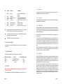
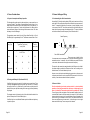
3.2.2
Pin
Colour
Function
Comments
1
Black
Ground
2
3
4
5
Red
Green
Yellow
Blue
Serial Out
Wheel Sensor Input
Tacho in
+5 volts Out
6
7
8
Violet
Brown
White
Anal. Channel 1i/p
Anal. Channel 2 I/p
+12 volts in
Connect to cable screen and
chassis
insulate
Connect to wheel sensor output
Connect to rpm sensor output
Connect to wheel sensor 5 volts
input
Insulate if not used
Insulate if not used
Connect to car‘s 12 volt supply
Driver Code
As with Session Number, Driver Code does not alter the way the system operates and is simply a code stored with each lap.
3.2.3
Track Code
The track code is another user parameter that is simply stored with each lap time
and available for later processing.
3.2.4
Main Channel
Analogue inputs must be from sensors that provide a 0 to + 5 volt output.
Use the +5 volts output and Ground to power potentiometers.
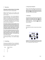
The Beacon transmits a beam of infra red light encoded with a channel number.
This channel number depends on the Beacon Control Knob setting and can be
from 1 to 4 inclusive. The Lap Timer will respond to the channel number set as
its Main Channel Number.
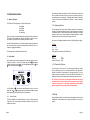
The wheel sensor should be connected to the black (GND), blue (+5V)
and Green (wheel sensor input) wires.
Set the main Channel Number to the channel number that you are going to use
on the Beacon.
Solder all connections carefully and insulate.
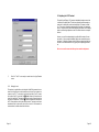
The Lap Timer will set this channel automatically if you point the beacon (set to
the channel you wish to use) at the IR Detector when the Main Channel is shown
on the display in Set Up Mode. Once channel number is displayed on the Lap
Timer, you will have to point the Beacon at the ground so that the IR Detector is
not receiving the channel code before being able to move on to the next set up
item.
2.3 Sensor Connections
The following sections apply to both the later type of Junction Box and the earlier
sensor loom.
NOTE Setting the Main Channel number to 0 will allow the system to respond to
PI System 1 beacons. These are installed at many Kart tracks and at motor racing circuits during some test days and meetings.
2.3.1 Wheel Sensor
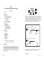
The wheel sensor cable has the following wires for connection:
3.2.5
Wheel Sensor Cable
When the IN Channel position on the Beacon is selected, a special code is transmitted which causes the IN display to be triggered in the car. This special code
is assigned to the Beacon during manufacture and is one of a set of 200. Although not impossible, it is very unlikely that your Beacon IN channel is the same
as another Beacon being used at the same time.
Brown
Black
Blue
connect to
+5 volts (NOT 12 volts)
wheel sensor output
ground
Junction Box Terminal
+5V
Wheel
GND
2.3.2 RPM
DO NOT connect the RPM terminals to the vehicle’s coil – THIS WILL DESTROY THE SYSTEM.
Use a separate sensor for RPM that is independent of the ignition system. This
Page 32
IN Channel
For the Lap Timer to respond to the IN code it must be set in its memory. You
can find out what the IN channel of your beacon is by watching the visible LED
when you switch it on (see Section 5), but the Lap Timer will set this code automatically if you point the Beacon, set to the IN channel, at the IR Detector when
the IN Channel is shown on the display in Set Up Mode. Once the IN code is
displayed on the Lap Timer, you will have to point the Beacon at the ground so
that the IR Detector is not receiving the IN code before being able to move on to
the next set up item.
Page 9