1
PCI – 951 Board
User’s Manual
Version: 1.01
Kontron Embedded Computers GmbH
0-0096-2834
Contents
Contents
Introduction ..........................................................................................................3
Symbols used in this Manual .................................................................................4
Important Instructions.........................................................................................5
Note on the Guarantee ..........................................................................................5
Exclusion of Accident Liability Obligation...............................................................5
Liability Limitation / Exemption from the Guarantee Obligation .............................5
Safety Instructions...............................................................................................6
Safety Instruction for the Lithium Battery ...............................................................7
Electrostatic Discharge (ESD)................................................................................7
Electromagnetic Compatibility................................................................................8
FCC Statement ......................................................................................................8
Scope of Delivery.................................................................................................9
Optional Parts ........................................................................................................9
Product Identification .............................................................................................9
Board Description..............................................................................................10
Features...............................................................................................................11
Extended Functions .............................................................................................13
Functional Diagram..............................................................................................14
Configurations ...................................................................................................15
CPU Installation ...................................................................................................15
Memory Installation..............................................................................................16
Jumpers on the PCI-951 ......................................................................................17
Jumpers Location on the PCI-951 ...................................................................18
Connectors on the PCI-951 .................................................................................22
External Interfaces ..........................................................................................23
On Board Connectors......................................................................................25
Watchdog Timer Configuration ............................................................................43
BIOS Configuration............................................................................................44
BIOS Setup ..........................................................................................................44
Standard CMOS Setup ........................................................................................46
Advanced BIOS Features ....................................................................................51
Advanced Chipset Features.................................................................................57
Integrated Peripherals..........................................................................................61
Power Management Setup ..................................................................................66
PCI-951 Board – User‘s Manual
1
Contents
PNP/PCI Configuration........................................................................................ 70
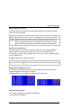
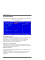
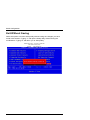
PC Health Status................................................................................................. 72
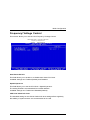
Frequency/ Voltage Control................................................................................. 73
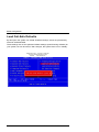
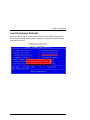
Load Fail-Safe Defaults....................................................................................... 74
Load Optimized Defaults ..................................................................................... 75
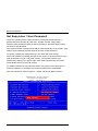
Set Supervisor / User Password.......................................................................... 76
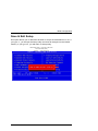
Save & Exit Setup ............................................................................................... 77
Exit Without Saving ............................................................................................. 78
Resources .......................................................................................................... 79
I/O Port Address Map .......................................................................................... 79
Interrupt Request Lines (IRQ) ............................................................................. 80
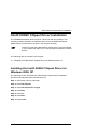
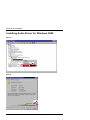
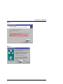
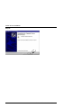
Intel® 845GV Chipset Driver Installation......................................................... 81
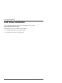
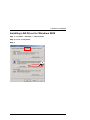
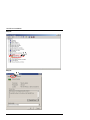
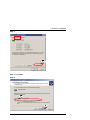
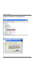
Installing the Intel® 845GV Chipset Driver for Windows 2000, XP ..................... 81
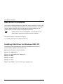
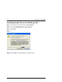
VGA Driver Installation ..................................................................................... 82
Installing VGA Driver for Windows 2000, XP....................................................... 82
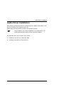
Audio Driver Installation................................................................................... 83
Installing Audio Driver for Windows 2000............................................................ 84
Installing Audio Driver for Windows XP ............................................................... 87
LAN Driver Installation...................................................................................... 88
Installing LAN Driver for Windows 2000 .............................................................. 89
Installing LAN Driver for Windows XP ................................................................. 94
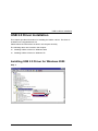
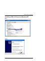
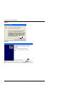
USB 2.0 Driver Installation ............................................................................... 95
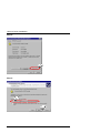
Installing USB 2.0 Driver for Windows 2000........................................................ 95
Installing USB 2.0 Driver for Windows XP........................................................... 99
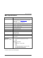
Main Specifications......................................................................................... 101
Electrical Specifications..................................................................................... 102
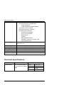
Power Specification........................................................................................... 103
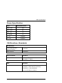
CE-Directives, Standards .................................................................................. 103
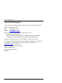
Technical Support ........................................................................................... 104
Returning Defective Merchandise ..................................................................... 105
2
PCI-951 Board – User’s Manual
Introduction
Introduction
Kontron Embedded Computers would like to point out that the information
contained in this manual may be subject to technical alteration, particularly as a
result of the continuos upgrading of Kontron Embedded Computers products. The
attached documentation does not entail any guarantee on the part of Kontron
Embedded Computers with respect to technical processes described in the
manual or any product characteristics set out in the manual. Kontron Embedded
Computers does not accept any liability for any printing errors or other
inaccuracies in the manual unless it can be proven that Kontron Embedded
Computers is aware of such errors or inaccuracies or that Kontron Embedded
Computers is unaware of these as a result of gross negligence and Kontron
Embedded Computers has failed to eliminate these errors or inaccuracies for this
reason. Kontron Embedded Computers expressly informs the user that this
manual only contains a general description of technical processes and
instructions which may not be applicable in every individual case. In cases of
doubt, please contact Kontron Embedded Computers.
This manual is protected by copyright. All rights are reserved by Kontron
Embedded Computers. Copies of all or part of this manual or translations into a
different language may only be made with the prior written consent of Kontron
Embedded Computers. Kontron Embedded Computers points out that the
information contained in this manual is continuously being updated in line with
the technical alterations and improvements made by Kontron Embedded
Computers to the products and thus this manual only reflects the technical status
of the products by Kontron Embedded Computers at the time of printing.
© 2003 by Kontron Embedded Computers
Printing and duplication, even of sections, is only permissible with the express
approval of
Kontron Embedded Computers GmbH
Oskar-von-Miller-Str. 1
85385 Eching near Munich
Germany
PCI-951 Board – User‘s Manual
3
Introduction
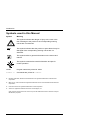
Symbols
used in this Manual
Symbol
Meaning
This symbol indicates the danger of injury to the user or the
risk of damage to the product if the corresponding warning
notices are not observed.
This symbol indicates that the product or parts thereof may be
damaged if the corresponding warning notices are not
observed.
This symbol refers to general information on the device and
manual.
This symbol comes before useful information and tips for
routine operation.
SYSM
Program names are printed in italics.
format a:
Commands are printed in Courier.
®
Microsoft, MS-DOS, Windows and Windows NT are registered trademarks of the Microsoft
Corporation.
®
IBM, PC-AT, OS/2 and PS/2 are registered trademarks of the International Business Machines
Corporation.
®
Intel and Pentium are registered trademarks of Intel Corporation.
®
Award is a registered trademark of Phoenix Technologies, Ltd.
Other product names cited in this manual may also be trademarks and are used here solely for
identification purposes.
4
PCI-951 Board – User’s Manual
Important Instructions
Important Instructions
This chapter contains safety instructions which must be observed when using
your PCI-951 board. The manufacturer’s instructions provide useful information
on your PCI-951 board.
Note
on the Guarantee
Due to their limited service life, parts which by their nature are subject to a
particularly high degree of wear (wearing parts) are excluded from the guarantee
beyond that provided by law. This applies, for example to the batteries.
Exclusion of Accident Liability Obligation
Kontron Embedded Computers shall be exempted from the statutory accident
liability obligation if the user fails to observe the safety instructions.
Liability Limitation / Exemption from the
Guarantee Obligation
In the event of damage to the device caused by failure to observe the hints in this
manual and eventually on the device (especially the safety instruction), Kontron
Embedded Computers shall not be required to honour the guarantee even during
the guarantee period and shall be exempted from the statutory accident liability
obligation.
PCI-951 Board – User‘s Manual
5
Safety Instructions
Safety Instructions
Please read this section carefully and observe the instructions for your own
safety and correct use of the board. Observe the warnings and instructions on the
board and in the manual.
The PCI-951 board is built and tested by Kontron Embedded Computers in
accordance with IEC / EN60950 and left the works in a perfectly safe condition.
In order to maintain this condition and ensure safe operation, the user must
observe the instructions and warnings contained in this manual.
Kontron Embedded Computers can only guarantee the safety, reliability and
performance of the board if all of the following safety instructions are observed.
q The PCI-951 board must be used in accordance with the instructions for use.
q The PCI-951 board is designed to be built into a system. The integration into
the system has to be done such, that the system complies with the
IEC / EN 60950 safety rules.
q In order to install the board into a system, ensure that the system is switched
off and the systems power cord is disconnected from the power source.
Disconnect all cable connections of peripheral devices from the system.
q Ensure that the DC operating voltages adheres to the specification given in
the “Electrical Specifications”.
q Only devices and components may be connected to the interfaces of the PCI951 board which fulfil the requirements of a SELV circuit (security low voltage
output) in accordance with IEC/EN60950.
q Please observe, that all cables attached to the PCI-951board must be duly
connected and fixed.
q If extensions are made to the PCI-951 board, the legal stipulations and the
board specifications must be observed.
6
PCI-951 Board – User’s Manual
Safety Instructions
q It must be assumed that safe operation is no longer possible,
if the device has visible damage or
if the device no longer functions.
In these cases the device must be shut down and secured against
unintentional operation.
q Repairs may only be carried out by a person authorised to do so by Kontron
Embedded Computers.
Safety Instruction for the Lithium Battery
The PCI - 951 board is equipped with a lithium battery. The lithium battery should
be replaced only in the factory.
Warning
There is a danger of explosion if the wrong type of battery is used
for replacement.
Electrostatic Discharge (ESD)
The components on the board are sensitive to static electricity. Care must
therefore be exercised at all times during handling and inspection of the PCI-951
board, in order to ensure the product integrity.
q Do not handle this product while it is outside its protective enclosure, while it
is not used for operational purposes, unless it is otherwise anti-static
protected.
q Unpack or install this product only at EOS/ESD safe work stations. When safe
work station are not guaranteed, it is important for the user to be electrically
discharged before touching the PCI-951 board with his/her hands or tools.
This is most easily done by touching a metal part of your system housing.
q Only hold the assemblies at the edge.
q Do not touch any connection pins or conductors on the assembly.
PCI-951 Board – User‘s Manual
7
Safety Instructions
Electromagnetic Compatibility
This device was developed for use in industrial applications and for business and
commercial areas as well as small companies. The EMC guideline 89/336/EWG
in the most recent version or the German EMC law shall apply. Insofar as the
user makes alterations or extensions to the device (e.g. installation of extension
cards) the preconditions for the CE conformity declaration (protection
requirements) may no longer be fulfilled.
FCC
Statement
This equipment has been tested and found to comply with the limits for a Class A
digital device, pursuant to Part 15 of the FCC Rules. These limits are designed to
provide reasonable protection against harmful interference when the equipment
is operated in commercial environment. This equipment generates, uses, and can
radiate radio frequency energy and, if not installed and used in accordance with
the instruction manual, may cause harmful interference to radio communications.
Operation of this equipment in residential area is likely to cause harmful
interference in witch case the user will be required to correct the interference at
his own expense.
8
PCI-951 Board – User’s Manual
Scope of Delivery
Scope of Delivery
Please check that your package is complete, and contains the items below
(according to the ordered unit configuration). If you discover damaged or missing
items, please contact your dealer.
q 1x PCI-951 Board PICMG (Full-Size)
q 1x Safety Instructions
q 1x IDE Cable Connector (40-pin) for CD-ROM
q 1x IDE Cable Connector (80-pin) for HDD
q 1x Cable Connector for 3.5” Floppy Drive
q 1x Serial Port and 1x Parallel Port Cable Connectors attached to a Mounting
Bracket
q 1x Serial Port Cable attached to a Slot Mounting Bracket
q 1x USB Cable Connector attached to a Slot Mounting Bracket with
double USB-Connector (type A)
q 1x Audio Slot Bracket
q 1x Y Cable Mini-DIN PS/2 Keyboard and Mouse
q 1x ATX Adapter Cable
q 1x CD-ROM with the required Drivers and the PCI-951 Board User’s Manual
Optional Parts
q DVI Adapter Card with Slot Bracket
Product Identification
The board is labelled at the rear side with the corresponding product identification
number.
Label
Product Identification
2-AXXX-XXXX
PCI-951 Board
The /"XXXX"/ group defines the ordered board configuration.
PCI-951 Board – User‘s Manual
9
Board Description
Board Description
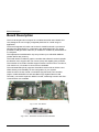
The PCI-951single board computer is a multifunctional full-size PICMG CPU
card, designed for use in highly integrated platforms for a wide range of
application.
The board integrates a Socket 478 Socket for Intel® Pentium® 4 processors.
Adopting the Intel® 845GV in combination with 82801DB (ICH4), the board
provides a PSB (processor side bus) of 400MHz or 533MHz by a bandwidth of
4.2 Gbytes/s.
The implemented Intel® 845GV chip set provides up to 2GB GDR SDRAM
(double DATA rate) memory.
The Intel® 845GV includes a graphic controller that offers 2D- and 3D graphic
acceleration and, supports the use of both (VGA) and digitally (DVI) monitors.
The onboard AC’97 audio CODEC supports stereo sound function. The Mic-In,
Line-Out/Line-In, CD Audio-In connectors are available.
The used 82801DB (ICH4) supports Ultra DMA-100 as well as USB 2.0 and
offers thereby more flexibility for the configuration of your system.
Other functions consist of dual 10/100 Base-T(X) Ethernet LAN controller
(Option: Intel® 82540EM 10/100/1000 Base-T(X) Gigabit Ethernet LAN
controller), one 32-bit expansion MiniPCI socket, Watchdog function and IrDAcommunication are available.
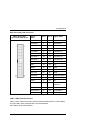
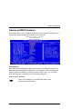
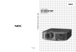
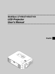
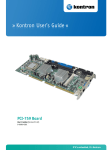
Fig. 1: PCI - 951 Board
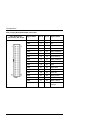
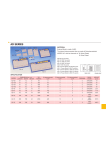
Fig. 2: PCI - 951 Board slot bracket with interfaces
10
PCI-951 Board – User’s Manual
Board Description
Features
Processor Socket: Intel® Socket 478.
Processor: Intel® Pentium® 4 and / or Celeron® CPU.
2
The CPU temperature is monitored via an I C sensor.
The Intel® Pentium® 4 uses a supply voltage (Vcore), witch is
generated from the 12V. It requires the extra 4-pin power
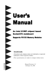
header from the PSU in order to function. (See Fig. 4: PCI - 951
Jumpers and connectors location)
Processor Side Bus Speed (FSB): 400 / 533MHz
Chipset: Intel® 845GV with Intel® 82801DB (ICH4) Chipset
Memory:
q Two 184-pin non-ECC DDR DIMMs, single-sided and/ or double-sided
up to 2GB as DDR200, DDR266 or DDR333.
BIOS: Award BIOS.
q The BIOS provides “Plug &Play” feature, which detects the PnP-compatible
peripheral devices and expansion cards automatically.
q ACPI Power management
DMI BIOS Support:
q Desktop Management Interface (DMI) allows users to download system
hardware-level information such as CPU type, CPU speed, frequencies and
memory size.
LPC I/O: Winbond W83627HF
PCI to ISA Bridge: ITE IT8888F
Parallel Port: One high-speed parallel port, that supports SPP/EPP/ECP mode.
Serial Port: Two 16550 UART compatible ports with:
q COM1 configurable as RS-232 and
q COM2 configurable as RS-232 / RS-422 / RS-485 (selectable by jumper
setting).
PCI-951 Board – User‘s Manual
11
Board Description
Enhanced IDE: Support two Bus Mastering IDE mode, up to 4 devices. Two IDE
interfaces for up to four devices, support PIO Modes up to 5 or Ultra DMA
33/66/100 IDE Hard Disk and ATAPI CD-ROM.
FDD Interface: supports two floppy drives (1.44MB, 2.88MB)
USB Interface: Two USB pin-header connectors (support 4 interfaces, compliant
with USB Specification Rev. 2.0)
Audio: AC’97 2.0 (AD1881A) CODEC compatible with stereo sound function,
which contained Mic-In, Audio Line-In / Line-Out.
Watchdog Timer: programmable ca. 1 to 256 sec.
PICMG Compliance: Fully compliant to PICMG 1.0 standards
VGA: Embedded Intel® 845GV with integrated VGA controller
q Simultaneous CRT display (VGA and DVI)
q 64-bits memory bus in 2/4/8/16/32 MB DDR SDRAM
q LCD panel that supports DVI
q CRT resolution: 1920x 1440 at 85 Hz
q resolution for digital flat panels: Up to 1280x 1024 at 60 Hz
q It support fast 2D and 3D graphics performance; enhance 3D feature set;
Improves platforms for DVD and Video playback and Enhance Multimedia
functionally
Ethernet: Intel® 82562ET / 82801DB
q The Intel® 82801DB ICH4 supports LAN functions for fast Ethernet (10/100
Mbit/s). In combination with Intel® 82562ET supports 10/100 Base-T
connection.
q The Intel® 82551QM provides a standard IEEE 802.3 Ethernet interface for
10/100 Base-TX applications (802.3, 802.3u, 802.3ab).
Keyboard and Mouse Connectors:
q Combined PS/2 keyboard and mouse connector on the board slot bracket.
q On board 7-pin header connector that supports an external keyboard and
mouse connector.
12
PCI-951 Board – User’s Manual
Board Description
IrDA Interface: Pin-header connector that allows to connect an external IrDA
module.
CompactFlash™ Socket (IDE compatible): allows the operation with a
TM
ComapctFlash Card (Type I, II).
MiniPCI Socket: allows the extension with a MiniPCI card.
Extended Functions
q Temperature Monitoring and Alert: The internal CPU temperature is
2
monitored via an I C sensor. When the temperature exceeds the safe heat
level an acoustical signal alerts the user or the system can be shut down.
q ATX-Power Control: Provides functions such as switching off by shutdown of
the operating system or Wake UP on LAN
q Modem Ring-On: Allows the system to be waked up through an external
modem. The system must be connected to the power source and the power
switch must be in On position.
q Wake On LAN: Allows the system to be waked up by the network. The
system must be connected to the power source and the power switch must be
in On position. Wake On LAN functions properly only with an ATX power
supply.
PCI-951 Board – User‘s Manual
13
Board Description
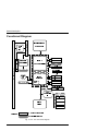
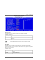
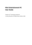
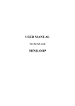
Functional Diagram
3
&
,
3&,
WR
,6$
,QWHO3HQWLXP
6RFNHW
''5',00
0
L
(WKHUQHW
Q
&RQWUROOHU
L
''5',00
L*9
9*$
9*$&RQWUROOHU
'9,
3
3
,
&
0
*
&
,
/$15-
&RPSDFW)ODVK
%DWWHU\
,'(
,&+
IRU
57&
,'(
'%
/$15-
[86%
/$1
3+<
[86%
$&
$XGLR/LQH,Q2XW
FRGHF
0LF,Q
/3&
&RQWUROOHU
36
.H\E0RXVH
,2
.H\E0RXVH
)ORSS\
%,26
6HULDO
)ODVK
3DUDOOHO
2QERDUGFRQQHFWRUV
/HJHQG
([WHUQDOLQWHUIDFHV
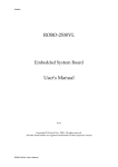
Fig. 3: PCI - 951 Functional diagram
14
PCI-951 Board – User’s Manual
Configurations
Configurations
This chapter provides information on how to use the jumpers and connectors
located on the PCI-951 in order to set up a workable system.
CPU Installation
The PCI-951 provides a 478-pin socket for Intel® Pentium® 4 or Celeron®
processors with mPGA form factor.
To install the CPU, insert it to the socket by aligning the notch of the CPU with
the one of the mPGA socket. For the CPU fan installation, refer to the installation
procedures of the fan manufacturer.
Due to mechanical incompatibility of the fan, we recommend not
to install the heat sink supplied with the boxed Intel®
Pentium® 4 processor.
Ensure that the contact between the CPU heat sink and the CPU
top surface is proper, in order to avoid CPU overheating problem,
that would cause your system to hang or be unstable.
PCI-951 Board – User‘s Manual
15
Configurations
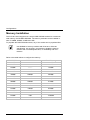
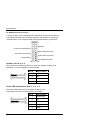
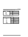
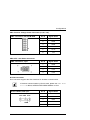
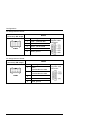
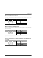
Memory Installation
The PCI-951 board supports two 184-pin DDR SDRAM sockets for a maximum
total memory of 2GB DDR SDRAMs. The memory modules can be installed in
size of 128MB, 256MB, 512MB and 1GB.
To populate the DDR SDRAM sockets, any of the socket can be populated first.
Use SDRAM of memory modules with PC2100 or PC2700
specification. Our suggest: you should not install the memory
modules with PC1600 specification, for availability and cost
reasons.
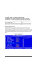
Refer to the table bellow to configure the memory:
16
DDR DIMM1
DDR DIMM2
Total Memory
128MB
--------
128MB
256MB
--------
256MB
512MB
--------
512MB
1GB
--------
1GB
128MB
128MB
256MB
128MB
256MB
384MB
128MB
512MB
640MB
256MB
128MB
384MB
256MB
256MB
512MB
256MB
512MB
768MB
256MB
1GB
1280MB
512MB
128MB
640MB
512MB
256MB
768MB
512MB
512MB
1GB
512MB
1GB
1536MB
1GB
1GB
2GB
PCI-951 Board – User’s Manual
Configurations
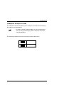
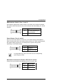
Jumpers on the PCI-951
The jumpers on the PCI-951 allow you to configure your CPU card according to
the needs of your applications.
In order to change a jumper setting, turn off the computer by
use of the ATX-power supply switch. Otherwise, the board
could be damaged.
The following examples show the conventions used in this section.
Jumper Open
1
2
1
2
Jumper Closed
PCI-951 Board – User‘s Manual
17
Configurations
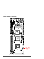
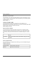
Jumpers Location on the PCI-951
-
-
$
*
9
6
0
%
.
3
-
3
5
,
3
-
\U
HW
WD
%
-
%' :
,QWHO
Q
D
)
UH
Z
R
3
3
-
-
O HW Q
,
-
1
$
/
7 (
3
-
-
(
,'
(
'
,
3
-
HOW ,Q /
2
:
1
$
)
V
K
&
0
7 2
3 &
/
1
$
/
3
-
0
2
&
&
'
)
3
-
:
3
%
6
8
3
/
&
%
6
8
3
/
&
,QWHO
*
,
9
'
3
/
&
3
/
&
3
-
:
3
0
0
,
'1
$
)
8
3
&
0
0
,
'
+12V ATX
PSU
-3
3
,7
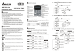
Fig. 4: PCI - 951 Jumpers and connectors location
18
PCI-951 Board – User’s Manual
Configurations
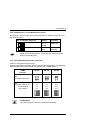
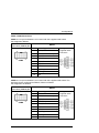
JP2: CompactFlash™ Card, Master/Slave Select
This jumper is used to select if the CompactFlash™ is master or slave device to
the secondary IDE.
JP2: Pin Header; DIP 2-pin
Setting
Function
2
Pin 1-2
Closed
Mastered
1
1
2
Pin 1-2
Open
Slave
(Default)
While using CompactFlash™-cards, only one device could be
used on secondary IDE.
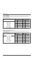
JP3, JP4: RS232/422/485 (COM1, 2) Selection
COM1 is configured as RS-232 only.
COM2 is selectable for RS232, RS-422 and RS-485 configuration. The following
table describes the jumper settings to configure the COM2 interface.
COM2
Function
RS-232
RS-422
RS-485
6 5
6 5
6 5
2 1
2 1
2 1
11-10
8-7
5-4
2-1
12-11
9-8
6-5
3-2
12-11
9-8
6-5
3-2
3-2-1
3-2-1
3-2-1
JP3:
Pin Header; DIP 6-pin
JP4 :
Pin Header; DIP 12-pin
Jumper Setting
(pin closed)
RS485 Mode:
The (RTS–) signal is used to activate the transmitter.
PCI-951 Board – User‘s Manual
19
Configurations
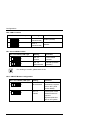
JP5: LAN1 Function
Setting
JP5: Pin Header; DIP 3-pin
Function
1
3
Pin 1-2
(Short/Closed)
Enable (Default)
1
3
Pin 2-3
(Short/Closed)
Disable
JP7: Clear CMOS Content
JP7: Pin Header; DIP 3-pin
Setting
Function
1
3
Pin 2-3
Closed
Clear CMOS
Content
1
3
Pin 1-2
Short/Closed
Normal Operation
(Default)
For clearing of content, please wait 10 sec.
JP11: ON/OFF Button Configuration
JP11: Pin Header; DIP 3-pin
Setting
Function
1
3
Pin 1-2
Short/Closed
The ON/OFF-button
switches the system
ON or OFF, (ATX
Power Mode).
1
3
Pin 2-3
Closed
The function of the
ON/OFF-button is
ignored.
System behaviour:
like an AT-system.
20
PCI-951 Board – User’s Manual
Configurations
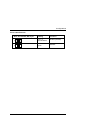
JP12: LAN2 Function
JP12: Pin Header; DIP 2-pin
Setting
Function
1
2
Pin 1-2
Short/Closed
Enable (Default)
1
2
Pin 1-2
Open
Disable
PCI-951 Board – User‘s Manual
21
Configurations
Connectors on the PCI-951
The connectors on the PCI-951 allow you to connect external devices such as
keyboard, floppy disk drives, hard disk drives, printers, etc. The following table
lists the connectors on PCI-951 and their respective functions.
External interfaces
LAN1, LAN2
RJ45 Connectors
VGA
VGA Connector
J4
Combined PS/2 Keyboard and Mouse Connector
On board connectors
J1
CD-Audio-In Connector
J2
Audio Connector
J3
Multifunctional Connector
J5
MiniPCI Socket
J6
External ATX Power Control Connector (+5VSB, PS_ON)
J8
Negative Voltages Power Connector (–5V, –12V)
KBMS
Keyboard/ Mouse External Connector
USB1
USB Header (Port 1, 2) Connectors
USB2
USB Header (Port 3, 4) Connectors
DVI
Connector for DVI Extension
IDE1, IDE2
IDE Connectors
FDC
Floppy Drive BOX Header Connector
PW1
Positive Voltage Power Connector (+3,3V, +5V)
PW2
ATX +12V Power Connector
IR
IrDA Connector
WOL
Wake On LAN Connector
LPT1
Parallel Port Connector
COM1, COM2
Serial Ports
CPU Fan
CPU Fan Power Connector
CHS Fan
Chassis Fan Power Connector
PWR Fan
Chassis Fan Power Connector
CF
CompactFlash
22
TM
Disk Connector (rear side)
PCI-951 Board – User’s Manual
Configurations
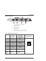
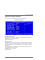
External Interfaces
1
2
3
4
Fig. 5: PCI-951 – User interface
1
LAN2 connector
2
LAN1 connector
3
VGA connector
4
PS/2 keyboard and mouse connector
LAN1, LAN2 Ethernet Connectors
PIN#
LAN1 or LAN2
10/100
Signal Name
Only LAN1
10/100/1000
(Option:82540EM)
Signal Name
1
TX+
MDI0+
2
TX-
MDI0-
3
RX+
MDI1+
4
NC
MDI2+
5
NC
MDI2-
6
RX-
MDI1-
7
NC
MDI3+
8
NC
MDI3-
LEFT
LED
LINK / ACTIVE
LINK / ACTIVE
RIGHT
LED
100/10
1000/100
PCI-951 Board – User‘s Manual
RJ45 (female)
23
Configurations
VGA-Interface - Connector
Pin
Signal name
1
red
2
green
3
blue
4
pulled to VCC
15-pin D-SUB socket (female)
5, 6, 7,8,10 GND
9
+5 V fused *
11
pulled to VCC
12
DDC-SDA *
13
HSYNC
14
VSYNC
DDC-SCL *
* used for DDC
PS/2 Keyboard and Mouse - Connector
Pin
Signal name
1
Keyboard data
2
Mouse data
3
GND
4
+5 V fused
5
Keyboard clock
6
Mouse clock
24
6 pin Mini-DIN socket (female)
PCI-951 Board – User’s Manual
Configurations
On Board Connectors
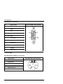
J1: CD-Audio-In Connector
J1: MINI Base; DIP 4-pin
Pin #
Signal Name
1
Left
2
GND
3
GND
4
Right
4 3 2 1
J2: Audio Connector
J2: Pin Header; DIP 10-pin
PCI-951 Board – User‘s Manual
Signal Name
Pin #
Pin #
Signal Name
LineOut-R
1
2
LineOut-L
GND
3
4
GND
LineIn-R
5
6
LineIn-L
GND
7
8
GND
Mic-In
9
10
VREF
25
Configurations
J3: Multifunctional Connector
A system chassis can be equipped with components, that provide acoustical
or/and light indication of the computer activities, and switches to change the
computer status. J3 is a 20-pin header that provides following connections.
Speaker
Power LED and Keylock
SMI / Hardware Swich
ATX Power ON Switch
Power LED Connector
Reset Switch
Hard Disk Drive LED
6SHDNHU3LQV
This connector provides an interface to connect a speaker for audio tone
generation. An 8-ohm speaker is recommended.
Pin #
Signal Name
2
Speaker out
4
NC
6
VCC
8
GND
3RZHU/('DQG.H\ORFN3LQV
The power LED shows, that your system is ready for use.
If the keylock is active, no keyboard entry is possible.
Pin #
26
Signal Name
1
Power LED
3
NC
5
GND
7
Keylock
9
GND
PCI-951 Board – User’s Manual
Configurations
60,+DUGZDUH6ZLWFK3LQVDQG
This interface supports the "Green switch" of a system. If the switch is pressed,
the system will be switched into the power-saving mode immediately (in a forced
manner).
Pin #
Signal Name
12
Ext. SMI (depending on
BIOS settings)
11
GND
3RZHU%XWWRQ3LQVDQG
This 2-pin connector allows to connect an “ATX Power Supply On/Off Button”.
When pressing this button, the system will be powered on. When pressing again,
the system will be powered off, or will be put into a power-saving mode,
depending on the BIOS settings.
Pin #
Signal Name
14
PWRBTN
13
Pulled up to VSB
It is supported only if the ATX function and a corresponding
power supply is used.
$OWHUQDWLYH&RQQHFWRUIRU3RZHU/('3LQVDQG
These pins can be used as an alternative port for a power LED.
Pin #
PCI-951 Board – User‘s Manual
Signal Name
16
Power LED
15
GND
27
Configurations
5HVHW6ZLWFK3LQVDQG
The reset switch allows to restart the system without turning the main power
switch off and then on again.
Pin #
Signal Name
18
Reset
17
GND
Depending on the software and operating system, some data
may be lost.
+DUG'LVN'ULYH/('&RQQHFWRU3LQVDQG
This connector allows to connect a hard drive activity LED. This LED will flash
when the HDD is being accessed.
Pin #
Signal Name
20
HDD-LED
19
Pulled up to VCC
J4: PS/2 Keyboard and PS/2 Mouse Connectors
See chapter “External Interfaces”.
28
PCI-951 Board – User’s Manual
Configurations
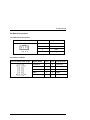
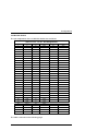
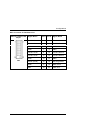
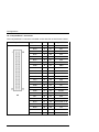
J5: MiniPCI Socket
The pin assignments of the J5 MiniPCI Socket are as follows:
SMD PCI Slot, 124-pin, Pin Assignments
Pin Name
Pin Name
Pin Name
1
X
51
AD21
101
GND
2
X
52
AD22
102
GND
3
X
53
AD19
103
X
4
X
54
AD20
104
X
5
X
55
GND
105
X
6
X
56
PAR
106
X
7
X
57
AD17
107
X
8
X
58
AD18
108
X
9
X
59
-CEB2
109
X
10
X
60
AD16
110
X
11
X
61
-IRDY
111
X
12
X
62
GND
112
X
13
X
63
VCC3
113
X
14
X
64
-FRAME
114
GND
15
X
65
-CLKRUN
115
X
16
X
66
-TRDY
116
X
17
-INTB
67
-SERR
117
X
18
VCC
68
-STOP
118
X
19
VCC3
69
GND
119
X
20
-INTA
70
VCC3
120
X
21
X
71
-PERR
121
X
22
X
72
-DEVSEL
122
-MPCIACT
23
GND
73
-CBE1
123
X
24
V3.3Aux
74
GND
124
3.3VAUX
25
CLK
75
AD14
26
-RST
76
AD15
27
GND
77
GND
28
VCC3
78
AD13
29
-REQ
79
AD12
30
-GNT
80
AD11
31
VCC3
81
AD10
32
GND
82
GND
The table continued on the following page.
PCI-951 Board – User‘s Manual
29
Configurations
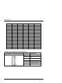
33
AD31
83
GND
34
-PME
84
AD9
35
AD29
85
AD8
36
X
86
-CBE0
37
GND
87
AD7
38
AD30
88
ACC3
39
AD27
89
ACC3
40
VCC3
90
AD6
41
AD25
91
AD5
42
AD28
92
AD4
43
RESV
93
X
44
AD26
94
AD2
45
-CBE3
95
AD3
46
AD24
96
AD0
47
AD23
97
VCC
48
IDSEL
98
X
49
GND
99
AD1
50
GND
100
R-WIP
J6: External ATX Power Control Connector
J6: Boxheader, (shrouded), DIP 6-pin
30
Pin #
Signal Name
1
PWRBTN
2
GND
3
PWRBTN
4
GND
5
PS-ON (soft on/off)
6
5V SB (standby +5V)
PCI-951 Board – User’s Manual
Configurations
J8: Negative Voltages Power Connector (–5V, –12V)
J8: MINI Base DIP 4-pin
Pin #
Signal Name
1
GND
2
-5V
3
GND
4
-12V
KBMS: Keyboard / Mouse External Connector
KBMS: Pin Header; DIP 7-pin
.%06
PCI-951 Board – User‘s Manual
Pin #
Signal Name
1
KB DAT
2
KEY
3
MS DAT
4
GND
5
VCC fused
6
KB-CLK
7
MS-CLK
31
Configurations
USB1 and USB2:
USB1 Header (Port 1, 2): the onboard USB1 pin-header supports two ports
(Port 1 and Port 2).
USB1: Port 1
USB1: Port 2
Pin # Signal Name
Pin # Signal Name
USB1: Pin Header; DIP 10-pin
1
VCC fused
2
VCC fused
3
D1-
4
D2-
5
D1+
6
D2+
7
GND
8
GND
9
Key
10
NC
USB2: USB Header (Port 2, 4)
USB2 Header (Port 3, 4): the onboard USB2 pin-header supports two ports
(Port 3 and Port 4).
USB2: Port 3
USB2: Port 4
USB2: Pin Header; DIP 10-pin
Pin # Signal Name Pin # Signal Name
32
1
VCC fused
2
VCC fused
3
D3-
4
D4-
5
D3+
6
D4+
7
GND
8
GND
9
Key
10
NC
PCI-951 Board – User’s Manual
Configurations
DVI: Connector for DVI Extension
DVI: Pin Header; DIP
20-pin
DVI
Signal Name
Pin #
Pin #
T.M.D.S Data 1+
1
2
T.M.D.S Data 2+
T.M.D.S Data 1-
3
4
T.M.D.S Data 2-
GND
5
6
GND
GND
7
8
GND
T.M.D.S CLK+
9
10
T.M.D.S Data 0+
T.M.D.S CLK–
11
12
T.M.D.S Data 0-
GND
13
14
GND
Power (fused)
15
16
Hot Plug Detect
GND
17
18
DDC DATA
KEY
19
20
DDC CLK
PCI-951 Board – User‘s Manual
Signal Name
33
Configurations
IDE1: Primary IDE Connector
IDE1: Boxheader,
(VKURXGHG), DIP 40-pin
34
Signal
Name
Pin #
Pin #
Signal Name
Reset IDE
1
2
GND
Host data 7
3
4
Host data 8
Host data 6
5
6
Host data 9
Host data 5
7
8
Host data 10
Host data 4
9
10
Host data 11
Host data 3
11
12
Host data 12
Host data 2
13
14
Host data 13
Host data 1
15
16
Host data 14
Host data 0
17
18
Host data 15
GND
19
20
Key
DRQ0
21
22
GND
Host IOW
23
24
GND
Host IOR
25
26
GND
IOCHRDY
27
28
GND permanent
DACK0
29
30
GND
IRQ14
31
32
NC
Address 1
33
34
80 pos. Cable
detection
Address 0
35
36
Address 2
Chip select 0
37
38
Chip select 1
Activity
39
40
GND
PCI-951 Board – User’s Manual
Configurations
IDE2: Secondary IDE Connector
IDE2: Boxheader,
(VKURXGHG), DIP 40-pin
Signal
Name
Pin #
Pin #
Signal Name
Reset IDE
1
2
GND
Host data 7
3
4
Host data 8
Host data 6
5
6
Host data 9
Host data 5
7
8
Host data 10
Host data 4
9
10
Host data 11
Host data 3
11
12
Host data 12
Host data 2
13
14
Host data 13
Host data 1
15
16
Host data 14
Host data 0
17
18
Host data 15
GND
19
20
Key
DRQ0
21
22
GND
Host IOW
23
24
GND
Host IOR
25
26
GND
IOCHRDY
27
28
GND permanent
DACK0
29
30
GND
IRQ14
31
32
NC
Address 1
33
34
80 pos. Cable
detection
Address 0
35
36
Address 2
Chip select 0
37
38
Chip select 1
Activity
39
40
GND
LAN1, LAN2: RJ45 Connectors
LAN1, LAN2: These connections support Ethernet data transfer of 10/100 Mbps.
The port LAN1 offers optionally also 10/100/1000 Mbps.
See chapter “External Interfaces”.
PCI-951 Board – User‘s Manual
35
Configurations
FDC: Floppy Drive Boxheader Connector
FDC: Boxheader,
(VKURXGHG DIP 34-pin
FDC
36
Signal Name
Pin #
Pin #
Signal Name
GND
1
2
RM/LC
GND
3
4
NC
GND
5
6
NC
GND
7
8
Index
GND
9
10
Motor enable 0
GND
11
12
Drive select 1
GND
13
14
Drive select 0
GND
15
16
Motor enable 1
GND
17
18
Direction
GND
19
20
Step
GND
21
22
Write data
GND
23
24
Write gate
GND
25
26
Track 00
GND
27
28
Write protect
NC
29
30
Read data
GND
31
32
Side 1 select
NC
33
34
Diskette
change
PCI-951 Board – User’s Manual
Configurations
PW1: Positive Voltage Power Connector (+3,3V, +5V)
PW1: Connector, P/B, 6P-M 180D
1
6
Pin #
Signal Name
1
GND
2
GND
3
GND
4
+3.3V
5
+3.3V
6
+5V
Pin #
Signal Name
1
GND
2
GND
3
+12V
4
+12V
PW2: ATX +12V Power Connector
PW2: Connector, 4-pin-
IR: IrDA Connector
This connector supports the IrDA interface for wireless communication.
If wireless communication by IrDA is used, please set 8$570RGH
6HOHFW in BIOS, INTEGRATED PERIPHERIAL to IrDA.
IR: Pin Header, DIP 4-pin
+5V IrRX IrTX
GND
PCI-951 Board – User‘s Manual
Pin #
Signal Name
1
+5V
2
N/A
3
IrRX
4
GND
5
IrTX
37
Configurations
VGA: VGA Connector
See chapter “External Interfaces”.
WOL: Wake On LAN Connector
WOL: is a 3-pin header for the Wake On LAN function of the CPU card.
Wake On LAN will function properly only with an ATX power
supply that provides 200mA standby current for the +5VSB
voltage.
WOL: Boxheader, (shrouded), 3-pin
Pin #
Signal Name
1
+5VSB
2
GND
3
Wake on LAN
LPT1: Parallel Port Connector
LPT1: Boxheader,
(shrouded), DIP 26-pin
/37
38
Signal Name
Pin #
Pin #
Signal Name
–Strobe
1
14
–AutoFeed
PD0, Data 0
2
15
–Error
PD1, Data 1
3
16
–Initialize
PD2, Data 2
4
17
–Select
PD3, Data 3
5
18
GND
PD4, Data 4
6
19
GND
PD5, Data 5
7
20
GND
PD6, Data 6
8
21
GND
PD7, Data 7
9
22
GND
–Acknowledge
10
23
GND
Busy
11
24
GND
Paper empty
12
25
GND
–Select
13
26
NC
PCI-951 Board – User’s Manual
Configurations
COM1, COM2 Serial Ports
COM1: the 10-pin boxheader is to be used with the supplied serial cable.
Pin assignment RS232:
COM1: Boxheader,
(shrouded), DIP 10-pin
&20
RS232
Pin #
Signal Name
1
DCD, Data carrier detect
2
DSR, Data set ready
3
RXD, Receive data
4
RTS, Request to send
5
TXD, Transmit data
6
CTS, Clear to send
7
DTR, Data terminal ready
RI, Ring indicator
9
GND, ground
10
NC
Pining on the
supplied cable
connector:
COM2: the 10-pin boxheader is to be used with the supplied serial cable. The
interface can be configured as RS232, RS422 or RS485.
Pin assignment as RS232:
COM2: Boxheader,
(shrouded), DIP 10-pin
&20
RS232
Pin #
Signal Name
1
DCD, Data carrier detect
2
DSR, Data set ready
3
RXD, Receive data
4
RTS, Request to send
5
TXD, Transmit data
6
CTS, Clear to send
7
DTR, Data terminal ready
RI, Ring indicator
9
GND, ground
10
NC
PCI-951 Board – User‘s Manual
Pining on the
supplied cable
connector:
39
Configurations
Pin assignment as RS422:
COM2: Boxheader,
(shrouded), DIP 10-pin
RS422
Pin #
&20
Signal Name
1
TXD–, Transmit data
3
TXD+, Transmit data
5
RXD+, Receive data
7
RXD–, Receive data
9
GND, ground
Pining on the
supplied cable
connector:
Pin assignment as RS485:
COM2: Boxheader,
(shrouded), DIP 10-pin
RS485
Pin #
&20
Signal Name
1
TXD–,
Transmit/Receive data
3
TXD+,
Transmit/Receive data
Pining on the
supplied cable
connector:
5
7
9
40
GND, ground
PCI-951 Board – User’s Manual
Configurations
CPU Fan: CPU Fan Power Connector
It is a 3-pin header that allows the connection of the CPU fan. The CPU fan must
be a 12V fan.
CPU Fan: Pin Header, 3-pin
Pin #
Signal Name
1
GND
2
+12V controlled
3
Rotation
CHS Fan: Chassis Fan Power Connector
It is a 3-pin header that allows the connection of the System fan. The System fan
must be a 12V fan.
CHS Fan: Pin Header, 3-pin
Pin #
Signal Name
1
GND
2
+12V
3
Rotation
PWR Fan: Chassis Fan Power Connector
It is a 3-pin header that allows to connect the Chassis fan. The Chassis fan must
be a 12V fan.
PWR Fan: Pin Header, 3-pin
PCI-951 Board – User‘s Manual
Pin #
Signal Name
1
GND
2
+12V controlled
3
Rotation
41
Configurations
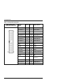
CF: CompactFlash™ Connector
The CompactFlash™ connector is located on the rear side of the PCI-951 board.
CompactFlash
CF
42
Signal Name
Pin #
Pin #
Signal Name
GND
1
26
GND
DO3
2
27
D11
DO4
3
28
D12
DO5
4
29
D13
DO6
5
30
D14
DO7
6
31
D15
CSO
7
32
CS1
GND
8
33
GND
GND
9
34
IORD
GND
10
35
IOWR
GND
11
36
WE
GND
12
37
IRQ25
VCC
13
38
VCC
GND
14
39
CSEL
GND
15
40
NC
GND
16
41
RESET
GND
17
42
IORDY
AO2
18
43
NC
A01
19
44
VCC
AO0
20
45
IDE-ACT
DO0
21
46
connected to 39
DO1
22
47
D8
DO2
23
48
D9
pulled down
24
49
D10
GND
25
50
GND
PCI-951 Board – User’s Manual
Configurations
Watchdog Timer Configuration
The function of the watchdog timer is to reset the system automatically and is
defined by Winbond W83627HF chip. If the Wachdog timer is activated, the
system could restart only when the Watchdog is not relocated within the installed
time interval.
Please observe: the watchdog timer has a tolerance of 20% for its
intervals.
For more information for the programming of the watchdog timer
refer to the on-line manual of the Winbond chip W83627HF
(www.winbond.com).
PCI-951 Board – User‘s Manual
43
BIOS Configuration
BIOS Configuration
This chapter describes the settings available in the Award BIOS for the PCI-951
board.
The Award BIOS (Basic Input/Output System) installed in your computer system’s
ROM supports Intel® Pentium® 4 and Celeron® processors in a standard IBMAT compatible I/O system.
BIOS Setup
The Award BIOS provides a Setup utility program for specifying the system
configurations and settings. The BIOS ROM of the system stores the Setup utility.
When you turn on the computer, the Award BIOS is activated.
Pressing the <Del> key immediately allows you to enter the Setup utility. If you
are a little bit late pressing the <Del> key, POST (Power On Self Test) will
continue with its test routines, thus preventing you from invoking the Setup. If you
still wish to enter Setup, restart the system by pressing the ”Reset” button or
simultaneously pressing the <Ctrl>, <Alt> and <Delete> keys. You can also
restart by turning the system Off and back On again. The following message will
appear on the screen:
3UHVV'(/!WR(QWHU6HWXS
In general, you press the arrow keys to highlight items, <Enter> to select, the
<PgUp> and <PgDn> keys to change entries, <F1> for help and <Esc> to quit.
When you enter the Setup utility, the Main Menu screen will appear on the
screen. The Main Menu allows you to select from various Setup functions and
exit choices.
44
The changes will be adopted only, if „SAVE & EXIT“ is selected
for quitting.
PCI-951 Board – User’s Manual
BIOS Configuration
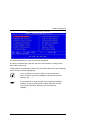
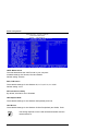
CMOS SETUP UTILITY-Copyright ( C ) 1984-2001
The fields selected by the user are coloured highlighted.
The keys (command keys) and their functions are indicated in a range at the
lower edge of the menu.
Underneath the command keys border are information about the current selected
menu function (coloured highlighted).
If your computer can not boot after you have made some
Setup changes, exists the possibility to reload the functional
settings. (vgl. …..)
We recommend to avoid changes of the chipset pre-settings
(default). These pre-settings are carefully selected, in order
to ensure the maximum efficiency with simultaneous
reliability.
PCI-951 Board – User‘s Manual
45
BIOS Configuration
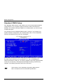
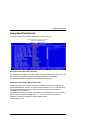
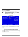
Standard CMOS Setup
The “Standard CMOS Setup” choice allows you to record some basic hardware
configurations in your computer system and set the system clock and error
handling. If the board is already installed in a working system, you will not need
to select this option.
You will need to run the Standard CMOS option, however, if you change your
system hardware configurations, the onboard battery fails, or the configuration
stored in the CMOS memory was lost or damaged.
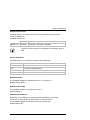
CMOS Setup Utility – Copyright (C) 1984-2001
Standard CMOS Features
AWARD BIOS INC.
At the bottom of the menu are the control keys for use on this menu. If you need
any help in each item field, you can press the <F1> key. It will display the
relevant information to help you. The memory display at the lower right-hand side
of the menu is read-only. It will adjust automatically according to the memory
changed. The following describes each item of this menu.
If the memory is not completely recognised, please ensure
that it correspond to the recommended specification.
46
PCI-951 Board – User’s Manual
BIOS Configuration
Date
Date:
indicate the date of the device. If you change the date setting,
enter the date in the format mm:dd:yyyy (month: day: year).
Date settings: Day:
Month:
Sun - Sat
1 - 12
Date:
1 - 31
Year:
1999 - 2099
Time
Time:
indicate the time of the device. If you change the time setting,
enter the time in the format hh:mm:ss (hours: minutes: seconds)
Time settings: Hour:
00 - 23
Minute:
00 - 59
Second:
00 - 59
IDE Primary / IDE Secondary
The onboard IDE connectors provide primary and pecondary channels for
connecting up to four IDE hard disks or other IDE devices. Each channel can
support up to two hard disks; the first is the “Master” and the second is the
“Slave”.
IDE HDD Autodetection
If you select this option, the parameters of the IDE devices are registered
automatically.
PCI-951 Board – User‘s Manual
47
BIOS Configuration
IDE Primary / IDE Secondary
None
Set to None, if no IDE equipment is installed, or you remove the
IDE device without replacing it.
Auto
If the hard disk supports this mode, the Setup menu reads the hard
disk parameters from the disk itself. You do not need to select the
parameters yourself. This will enable auto detection of your IDE
drives and CD-ROM drive during POST.
Manual
You have to enter the parameters of the IDE devices manually.
Please only use, if Auto does not work correctly
Some data may be lost, if you made changes of the already
installed IDE devices subsequently.
Capacity
This entry (size) results automatically from the following
data.
CYLS:
Number of cylinders
HEAD:
Number of read/write heads
PRECOMP:
Write pre-compensation cylinder
LANDZ:
Landing zone
SECTOR:
Number of sectors
Access MOD (only for IDE HDDs)
CHS
HD < 528MB
LBA:
HD > 528MB or different CF-devices
Large:
To use with MS-DOS only
Auto:
The optimal mode is selected by the BIOS automatically.
48
PCI-951 Board – User’s Manual
BIOS Configuration
The specifications of your drive must match with the drive table.
The hard disk will not work properly, if you enter incorrect
information in these fields. If your hard disk drive type is not
matched or listed, you can use Manual to define your own drive
type manually. If you select the option Manual, the HDD referred
information should be registered manually.
Drive A / Drive B
This field determines the type of the floppy disk drives, which are installed in your
system.
The available settings are:
1.44MB - 3.5 in.
360KB - 5.25 in.
1.2MB - 5.25 in.
720KB - 3.5 in.
2.88MB – 3.5 in.
A 3.5“ Floppy disk drive with 1.44MB is installed.
None
The floppy disk drive is not installed.
Video
This field allows you to select the type of the video card installed in your system.
Available settings:
EGA/VGA(default) For EGA, VGA, SEGA, SVGA or PGA monitor adapters.
CGA 40
Power up in 40 column mode (only for DOS).
CGA 80
Power up in 80 column mode (only for DOS)..
MONO
For Hercules or MDA adapters.
PCI-951 Board – User‘s Manual
49
BIOS Configuration
Halt On
This field specifies the errors which determine the interruption of the boot
procedure.
All errors (Default)
The boot procedure stops, whenever the BIOS
detects an error.
No errors
The boot procedure will be not halted for any
error that may be detected.
All, But Keyboard
The boot procedure will not be halted for a
keyboard error; it will stop for all other errors
All, But Diskette
The boot procedure will be not halted for a
disk error; it will stop for all other errors.
All, But Disk/Key
The boot procedure will be not halted for a
key- board or disk error; it will stop for all
others.
If the system stops because of an error, press the F1-key to
continue the boot procedure. The system does not start in such
a case independently.
50
PCI-951 Board – User’s Manual
BIOS Configuration
Advanced BIOS Features
This section allows you to configure and improve your system and allows you to
set up some system features according to your preference.
CMOS Setup – Copyright ( C ) 1984-2001
Advanced BIOS Feature
AWARD SOFTWARE, INC.
Virus Warning
This setting (when Enabled) protects the boot sector and partition table of your
hard disk against accidental modifications. If an attempt is made, the BIOS will
halt the system and display a warning message. If this occurs, you can either
allow the operation to continue or run an anti-virus program.
Default setting: Disabled.
Note: The message is not visible under graphic user
surfaces such as Windows.
PCI-951 Board – User‘s Manual
51
BIOS Configuration
CPU L1 & L2 Cache
This setting allows you to enable or disable the Level-1 and Level-2 cache
function.
Enabled (Default):
L1 and L2 Cash are enabled.
Disabled
L1 and L2 Cash are disabled.
Quick Power On Self Test
This field determines whether booting is to be shortened.
Enabled (Default):
Certain tests are not carried out during booting. This
accelerates the system start-up.
Disabled
The complete system tests will be carried out during the
POST.
First/ Second/ Third Boot Device
These fields specify the sequence in which the BIOS searches the drives of the
system, to boot the operating system.
The available options include: Floppy, LS120, HDD-0, SCSI, CDROM, HDD-1,
HDD-2, HDD-3, ZIP 100, USB-FDD, USB-ZIP, USB- CDROM, USB- HDD, LAN
and Disabled.
Default settings:
First Boot Device
Floppy
Default
Second Boot Device
HDD-0
Default
Third Boot Device
LS120
Default
Boot Other Device
This setting allows you to boot the operating system from other devices other
than the ones selected in the First/Second/Third Boot Device.
Default setting: Enabled.
52
PCI-951 Board – User’s Manual
BIOS Configuration
Swap Floppy Drive
This field allows you to change the drive letters of the disc drives.
Enabled (Default): Drive A: becomes B: and drive B becomes A.
Disabled
The drive letters are not changed.
Boot Up Floppy Seek
When Enabled, the BIOS will seek whether or not the floppy drive installed has
40 or 80 tracks.
360K type has 40 tracks while 760K, (1.2M and 1.44M) all have 80 tracks.
Default setting: Enabled.
Boot Up NumLock Status
This allows you to activate the NumLock function after you power up the system.
On (Default):
The number PAD of the keyboard functions in number mode.
Off:
The number PAD of the keyboard functions in cursor mode.
Gate A20 Option
This field allows you to select how Gate A20 is working. Gate A20 is a device
used to address memory above 1 MB.
Fast (Default):
The access is made by the chip set.
Normal:
The access is made by the keyboard controller.
PCI-951 Board – User‘s Manual
53
BIOS Configuration
Typematic Rate Setting
This field allows you to specify the repetition rate of the keyboard.
Enabled:
A character sequence appears on the screen, as long as you
keep the key pressed.
Disabled (Default): When a key is held down continuously, only one indication
appears on the screen.
Typematic Rate (Chars/Sec)
This field allows you to select, how quickly (characters/second) the keyboard
entry (repetition of characters) is to take place.
6 (Default):
Six (6) Chars/Sec
6 to 30
6, 8, 10, 12, 15, 20, 24, 30 Chars/Sec
Typematic Delay (Msec)
These settings allow you to select the time interval for displaying the first and
second characters.
By default, this setting is set to 250msec.
250 (Default):
250 Msek.
250-1000
250, 500, 750, 1000 Msek.
54
PCI-951 Board – User’s Manual
BIOS Configuration
CMOS Setup – Copyright ( C ) 1984-2001
Advanced Chipset Feature Setup
AWARD SOFTWARE, INC.
Security Option
This field allows you to limit the access to the System and Setup.
Available settings are:
Setup (Default): The password is required only for the access to the BIOS.
System
The password is required each time when the computer
boots up.
If the installed password is empty, then no inquiry is made.
APIC Mode
This field is used to enable or disable the APIC (Advanced Programmable
Interrupt Controller). Due to compliance with PC2001 design guide, the system is
able to run in APIC mode.
Available settings:
Enabled (Default):
APIC mode will expand available IRQ resources for the
system.
Disabled:
APIC is switched off.
PCI-951 Board – User‘s Manual
55
BIOS Configuration
MPS Version Control For OS
This field allows you to select which MPS (Multi-Processor Specification) version
is used. You have to select the MPS version supported by your operating system.
Available settings: 1.4 and 1.1.
Default setting: 1.4.
OS Select for DRAM > 64MB
This field determines whether the storage area over 64 MByte is to be
administrated by the operating system OS/2. If is used the operating system OS/2
select the option OS2 here, otherwise Non-OS2.
Default setting: Non-OS2.
Report No FDD For WIN 95
This field determines whether the BIOS should inform the operating system
Windows 95 whether a floppy disc drive is present or not. This function avoids
unnecessary waiting times under Windows 95. Available settings are Yes and
No.
Yes:
Windows 95 should not look for a floppy disc drive if none is
present.
No (Default):
Windows 95 should ascertain itself whether a floppy disc drive
is present.
Small Logo (EPA) Show
This option allows you to determine if the EPA Logo is to be indicated during the
bootup on the screen.
Available settings are:
Enabled (Default):
Show the EPA screen logo.
Disabled:
No show EPA screen logo.
56
PCI-951 Board – User’s Manual
BIOS Configuration
Advanced Chipset Features
This Setup menu controls the configuration of the board chipset.
CMOS Setup Utility – Copyright © 1984-2001
Advanced CHIPSET FEATURES
AWARD
SOFTWARE INC.
DRAM Timing Selectable
This field allows you to select the timing of the DDR DRAM memory modules.
Available settings: By SPD and Manual.
Default setting: By SPD.
CAS Latency Time
This field allows you to select the latency between access time from the “Read”
command of the memory controller to the time of the delivering the requested
data. The manufacturer of this board sets this value, according to the installed
DDR DRAM.
Do not change the values in this field, unless you change specifications of the
installed DRAM or the installed CPU.
Available settings: 1.5, 2 and 2.5 .
Default setting: 1.5.
PCI-951 Board – User‘s Manual
57
BIOS Configuration
Activity to Precharge Delay
This setting controls the number of clock cycles for DRAM to be allowed to
precharge from the active state. Available settings : 7, 6, and 5.
Default setting: 7. (Do not change the default setting)
DRAM RAS# to CAS# Delay
You can select RAS to CAS Delay time in CLKs of 2/2 or 3/3. The manufacturer
of this board sets this value, according to the installed DDR DRAM. Do not
change this value, unless you change specifications of the installed DRAM (DDR)
or the installed CPU.
Available settings are: 2 and 3.
Default setting: 3.
DRAM RAS# Precharge
This field allows you to select how much time between two memory accesses
passes. Available settings are 2 und 3.
Default setting: 3
Turbo Mode
This setting controls the DRAM running to Turbo mode or not.
Setting option: Disabled (default), Enabled.
Memory Frequency For
This field allows you to configure the clock frequency of the installed SDRAM.
Available settings: Auto (Default), DDR 200, DDR 266, DDR 333.
System BIOS Cacheable
The setting of Enabled allows caching of the system BIOS ROM at
F000h-FFFFFh, resulting in better system performance. This memory area can
be buffered (in the internal Cache of the CPU). The accesses to the BIOS
become faster.
Available settings are Enabled (Default) and Disabled.
58
PCI-951 Board – User’s Manual
BIOS Configuration
Video BIOS Cacheable
The video BIOS occupies the range from C000:0 to maximally DFFF:0. This
range can be buffered (in the internal Cache CPU). The accesses to the video
BIOS become faster. Available settings are: Enabled (default) and Disabled.
The settings „Video BIOS Cacheable“ and „System BIOS
Cacheable“ offer practically only under DOS an acceleration.
Modern operating systems did not use the BIOS.
Memory Hole At 15M-16M
In order to improve performance, certain space in memory can be reserved for
ISA cards. This memory must be mapped into the memory space below 16 MB.
Available settings are Enabled and Disabled (default).
Delayed Transaction
The chipset has an embedded 32-bit posted write buffer to support delay
transactions cycles. Settings options are Enabled (default) and Disabled.
The compatibility to the PCI specification version 2.1 is only ensured, if the buffer
is activated (Enabled).
Delay Prior to Thermal
When the CPU temperature reaches a factory preset level, a thermal monitoring
mechanism will be enabled following the appropriate timing delay specified in this
field. With the thermal monitoring enabled, clock modulation controlled by the
processor’s internal sensor is also activated to keep the processor within
allowable temperature limit.
Available settings: 4 Min, 8 Min, 16 Min (Default), 32 Min.
AGP Aperture Size (MB)
The field sets aperture size of the graphics. The aperture is a portion of the PCI
memory address range dedicated for graphics memory address space. Host
cycles that hit the aperture range are forwarded to the AGP without any
translation. Available settings are 4M, 8M, 16M, 32M, 64M, 128M and 256M.
Default setting: 64M.
PCI-951 Board – User‘s Manual
59
BIOS Configuration
On-Chip VGA
The available settings for the On-Chip VGA are Enabled and Disabled.
Default setting: Enabled.
On-Chip Frame Buffer Size
The available settings for the On-Chip Frame Buffer Size are 8MB and 1MB.
Default setting: 8MB.
Boot Display
The available settings for the Boot Display are Auto, CRT, TV and EFP.
Default setting: Auto.
60
PCI-951 Board – User’s Manual
BIOS Configuration
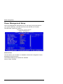
Integrated Peripherals
This option sets your hard disk configuration, mode and port.
CMOS Setup Utility – Copyright © 1984-2001
INTEGRATED PERIPHERALS
AWARD
SOFTWARE INC.
On-Chip Primary/Secondary PCI IDE
The integrated peripheral controller contains an IDE interface with support for two
IDE channels. Available settings are Enabled (Default) and Disabled.
The setting Enabled is available for each channel separately.
IDE Primary/Secondary Master/Slave PIO
These fields allow your system hard disk controller to work faster. Rather than
have the BIOS issue a series of commands that transfer to or from the disk drive,
PIO (Programmed Input/Output) allows the BIOS to communicate with the
controller and CPU directly.
The system supports five modes, numbered from 0 (default) to 4, which primarily
differ in timing. Available settings are: 0, 1, 2, 3, 4 and Auto. When Auto is
selected, the BIOS will select the best available mode.
Default setting: Auto.
PCI-951 Board – User‘s Manual
61
BIOS Configuration
IDE Primary/Secondary Master/Slave UDMA
These fields allow you to improve the disk I/O through the Ultra DMA feature. The
available settings are Auto and Disabled.
Default setting: Auto
USB Controller
The available settings for this field are Enabled and Disabled.
Default setting: Enabled.
USB 2.0 Controller
The available settings for this field are Enabled and Disabled.
Default setting: Enabled.
USB Keyboard Support
This field allows you to switch on or off the support for USB keyboards (for
operating systems without USB supporting).
Available settings are Enabled and Disabled.
Default setting: Disabled.
This function should not be activated, if the operating system
provides USB support.
AC97 Audio
The available settings for this field are Auto and Disabled.
Default setting: Auto.
Init Display First
This field allows you to select the VGA card that is to be initialised first. Available
choices: PCI-slot or AGP card.
Available settings are Onboard/AGP und PCI Slot.
Default setting: Onboard/AGP.
Onboard LAN Controller
The field determines whether the onboard LAN controller will be activated.
Available settings are Enabled and Disabled.
Default setting: Enabled.
62
PCI-951 Board – User’s Manual
BIOS Configuration
IDE HDD Block Mode
If your hard disk supports the block mode, select Enabled for the automatic
determination of the number of the blocks per request. Several sectors can be at
the same time read/written. The data transfer rate will be increased.
Available settings are Enabled and Disabled.
Default setting: Enabled.
Onboard FDC Controller
This field allows you to activate or to deactivate the on board integrated floppy
disk controller.
Enabled (Default): The floppy disk controller of the board is used.
Disabled
If a supplementary floppy disk controller is used or
the system is not equipped with a floppy disk drive.
Onboard Serial Port 1&2
These fields allow you to select the onboard serial ports and their addresses.
Available settings are:
Default
Available settings (without default setting)
Serial Port 1 3F8/IRQ4
2F8/IRQ3 / 3E8/IRQ4 / 2E8/IRQ3 / Disabled / Auto
Serial Port 2 2F8/IRQ3
3F8/IRQ4 / 3E8/IRQ4 / 2E8/IRQ3 / Disabled / Auto
PCI-951 Board – User‘s Manual
63
BIOS Configuration
CMOS Setup Utility – Copyright © 1984-2001
INTEGRATED PERIPHERIAL
AWARD
SOFTWARE INC.
UART Mode Select
This field determines the UART mode in your computer.
Available settings are Normal, IrDA and ASKIR.
Default setting: Normal.
RxD, TxD Active
The available settings for this field are Hi,Lo / Lo,Hi / Lo,Lo / Hi,Hi.
Default setting: Hi,Lo.
IR Transmission Delay
By default, this field is set to Enabled.
UR2 Duplex Mode
The available settings for this field are Half (default) and Full.
Use IR Pins
The available settings for this field are IR-Rx2Tx2 (default) and RxD2, TxD2.
The setting depends on the used infrared transmitter and the
used end device.
64
PCI-951 Board – User’s Manual
BIOS Configuration
Onboard Parallel Port
This field allows you to select the resources (I/O address and IRQ) for the
onboard parallel port.
Available settings are:
Default
Parallel Port 378/IRQ7
Available settings (without default setting)
278/IRQ5 / 3BC/IRQ7 / Disabled
The ECP or EPP mode is not supported, if the setting option is
3BC.
Parallel Port Mode
This field allows you to select the modes of the parallel port.
SPP
Normal Printer Port
EPP
Enhanced Parallel Port
ECP
Extended Capabilities Port
ECP+EPP
Enhanced Parallel and Extended Capabilities Port
Normal
Normal Parallel Port
ECP Mode Select
The available settings for this field are EPP 1.7 and EPP 1.9.
Default setting: EPP 1.7.
ECP Mode Use DMA
The available settings for this field are 3 and 1.
Default setting: 3.
PWRON After PWR-Fail
Depending on this setting, the system behaves differently, if the power
connection is restored after a power failure or interrupt occurs.
The available settings for this field are Off, On, Former-Sts.
Default setting: Off.
PCI-951 Board – User‘s Manual
65
BIOS Configuration
Power Management Setup
The Power Management Setup allows you to use energy saving functions for
your system effectively. It will shut down the hard disk and turn off video
controller after a period of inactivity.
CMOS Setup Utility – Copyright © 1984-2001
POWER MANAGEMENT SETUP
AWARD
SOFTWARE, INC.
ACPI Function
This field allows you to enable or to disable the Advanced Configuration Power
Management (ACPI) function.
The available settings are Enabled and Disabled.
Default setting: Enabled.
66
PCI-951 Board – User’s Manual
BIOS Configuration
Power Management
This field allows you to select the type of power saving management modes.
Available settings for this field are:.
User Define
(Default)
Each of the ranges is from 1 min. to 1h.
Exception: the ranges can be set for the HDD from
1 min. to 15 min.
Min. Power Saving
Minimum power management.
Max. Power Saving
Maximum power management.
In order to ensure the CPU overheat protection, the Power
Management field should not be set to Disabled; (the
setting Disabled is not available).
Video Off Method
This field defines the Video Off features.
The available settings are:
DPMS
Allows the BIOS to control the video card if it supports
the DPMS feature.
Blank Screen
This option only writes blanks to the video buffer.
V/H SYNC+Blank Video off function depend on display’s H-SYNC & VSYNC signal.
Video Off In Suspend
This field determines whether the monitor will be switched into the power save
mode or not.
Available settings are: Yes (Default) and No.
Suspend Type
Available settings for this field are: Stop Grant, PwrOn Suspend.
Default setting: Stop Grant.
Modem Use IRQ
This field names the interrupt request (IRQ) line assigned to the modem (if any)
on your system. Activity of the selected IRQ always wakes up the system.
Available settings are: NA, 3 (Default), 4, 5, 7, 9, 10, 11.
PCI-951 Board – User‘s Manual
67
BIOS Configuration
Suspend Mode
When Enabled, after the set time of system inactivity all devices, except the CPU,
will be shut off.
Available settings are: Enabled and Disabled (Default).
HDD Power Down
This field determines whether the hard disk will be powered down or not.
Available settings are: Disabled (Default), 1Min, 2Min, 3Min, 4Min, 5Min, 6Min,
7Min.
After the set time (Min. = minutes) of system inactivity, the hard disk drive will be
powered down.
Default setting: Disabled (The system will be not powered down the hard disk).
Soft-Off by PWR-BTTN
This field defines the power-off mode when using an ATX power supply.
The available settings are Instant Off and Delay 4 sec.
Default setting: Instant-Off.
The instant-Off mode allows powering off immediately upon pressing the power
button. In the Delay 4 Sec. mode, the system powers off when the power button
is pressed for more than four seconds or places the system in a very low-powerusage state, with only enough circuitry receiving power to detect power button
activity or Resume by Ring activity (see next field) when pressed for less than 4
seconds.
CPU THRM-Throttling
This field allows you to reduce the CPU internal working frequency.
Available settings are: 12,5 %, 25%, 37,5%, 50%, 62,5%, 75%, 87,5%.
(e.g.: for a set value of 12%, the CPU working frequency will be stopped to 12%.)
Default setting: 50.0 %.
Wake-Up by PCI Card & Power On by Ring
These fields specify whether the system will be waked up from power saving
modes, when activity or input signal of the specified hardware peripheral or
component is detected.
The available settings are Enabled und Disabled.
Default setting: Enabled.
To use the function “Wake Up On Ring“ or “Wake Up On
LAN” you have to install a modem/LAN card, that supports
the “power on” function.
68
PCI-951 Board – User’s Manual
BIOS Configuration
Resume by Alarm
The available settings are Enabled and Disabled (Default).
This field allows you to enable or to disable the resumption of the system
operation. When Enabled, the user can set the Date Alarm and Time Alarm.
Date ( of Month) Alarm
Default
Available settings
0
0-31
Time (HH:MM:SS:) Alarm 00:00:00
00-23 / 00-59 / 00-59
Reload Global Timer Events
The HDD, FDD, COM, LPT Ports, and PCI PIRQ are I/O events which can
prevent the system from entering a power saving mode or can wake up the
system from such a mode. When an I/O device wants to gain the attention of the
operating system, it signals this by causing an IRQ to occur. When the operating
system is ready to respond to the request, it interrupts itself and performs the
service.
CMOS Setup Utility – Copyright © 1984-2001
POWER MANAGEMENT SETUP
AWARD
SOFTWARE, INC.
PCI-951 Board – User‘s Manual
69
BIOS Configuration
PNP/PCI Configuration
This option configures the PCI bus system and the Plug & Play function.
Change of the default settings in this menu may only carried out
by very experienced users. Incorrect settings can cause
malfunctions or damage of the board.
CMOS Setup Utility – Copyright © 1984-2001
PNP/PCI CONFIGURATION
AWARD
SOFTWARE INC.
PNP OS Installed
This field determines the Plug&Play function. Plug&Play means that added
components are automatically recognised and installed if they support automatic
recognition.
The available settings are No (Default) and Yes.
Yes:
The operating system assumes part of the Plug&Play functions. This
setting should only be selected if the operating system supports
Plug&Play (e. g. Windows 95 or higher).
No:
(Default)
The system BIOS assumes the recognition of the components and
assigns the resources.
70
PCI-951 Board – User’s Manual
BIOS Configuration
Reset Configuration Data
This field determines whether the configuration data are newly initiated (reset)
when the device is started.
Disabled The installed components and drives are initiated with the existing
(Default): configuration data. There is no updating when the device is started.
Enabled: After the device is started the old configuration data are reset. The
current configuration data are registered by the Plug&Play function.
The installed components and drives are initiated with these data.
Resources Controlled by
This field determines by whom the system resources are to be administrated.
This PnP BIOS can configure all of the boot and PnP compatible devices
automatically. However, this capability needs you to use a PnP operating system
such as Windows 95.
Available settings are: Auto and Manual.
Auto(ESCD) (Default): The BIOS administrates the resources automatically.
Manual
The user determines the resources assignment.
IRQ Resources/ DMA Resources
To configure the IRQ Resources and the DMA Resources, these Resources
Controlled By field should be set to Manual.
Available settings are: PCI/ISA PnP (Default) and Legacy ISA.
PCI/ VGA Palette Snoop
The available settings are Enabled and Disabled.
Leave this filed at Disabled.
PCI-951 Board – User‘s Manual
71
BIOS Configuration
PC Health Status
This section shows the states of the CPU, fans, warning for overall system status.
CMOS Setup Utility – Copyright © 1984-2001
PC Health Status
AWARD
SOFTWARE INC.
CPU Warning Temperature
The available settings are Disabled (Default), 50°C (122°F), 53°C (127°F), 56°C
(133°F), 60°C (140°F), 63°C (145°F), 66°C (151°F) und 70°C (158°F).
When Enabled, you can set a temperature limit value for the temperature
monitoring of the CPU. The system will warn the user, when the CPU
temperature has reached the set temperature value.
Temperature/ Fan Speed/ Voltages
These fields allow you to observe the parameters of the hardware monitoring
function feature of the system. The values are read-only values for the monitoring
of the system and show the PC health status.
Shutdown Temperature
The Available settings are Disabled (Default), 60°C (140°F), 65°C (149°F), 70°C
(158°F) und 75°C (167°F).
This field allows you to set the Shutdown Temperature level for the processor.
The system will be shut down, when the processor has reached the set
temperature.
72
PCI-951 Board – User’s Manual
BIOS Configuration
Frequency/ Voltage Control
This section allows you to set the CPU Frequency/ Voltage Control.
CMOS Setup Utility – Copyright © 1984-2001
Frequency / Voltage Control
AWARD
SOFTWARE INC.
Auto Detect PCI Clk
This field allows you to enable or to disable auto detect PCI Clock.
Available settings are: Enabled (Default) and Disabled.
Spread Spectrum
This field allows you to set the CPU Clock / Spread Spectrum.
The setting Enable is recommended for low EMI radiation.
Available settings are: Enabled and Disabled (Default).
CPU Host/ 3V66/ PCI Clock
The standard setting for this field is Default. All other settings affect negatively
the stability of system and are not recommended to be used.
PCI-951 Board – User‘s Manual
73
BIOS Configuration
Load Fail-Safe Defaults
By this option the system can reload all default settings, which are permanently
stored in the BIOS-ROM.
These settings are not the optimised default settings (manufacturing defaults) for
your system, but can be used, if after changes, the system does not run reliably.
CMOS Setup Utility – Copyright © 1984-2001
Load Fail-Safe Defaults Setup Utility
AWARD
SOFTWARE INC.
74
PCI-951 Board – User’s Manual
BIOS Configuration
Load Optimized Defaults
This option allows you to load the default values of your system configuration.
These default settings (manufacturing settings) are optimal and enable all high
performance features.
CMOS Setup Utility – Copyright © 1984-2001
Load Optimized Defaults Setup Utility
AWARD
SOFTWARE INC.
PCI-951 Board – User‘s Manual
75
BIOS Configuration
Set Supervisor / User Password
These two options set the system password. Supervisor Password sets a
password that will be used to protect the “System” and the “Setup utility”.
Starting of the operating system as well as changes in the BIOS Setup require
the enter of this password.
User Password sets a password that will be used exclusively on the system. Only
starting of the operating system requires the enter of this password.
To specify a password, highlight the type you want and press <Enter>.
The Enter Password: message prompts on the screen. Type the password, up to
eight characters in length, and press <Enter>. The system confirms your
password by asking you to type it again. After setting a password, the screen
automatically returns to the main screen.
To disable a password, just press the <Enter> key when you are prompted to
enter the password. A message will confirm the password to be disabled.
See also subsection “Security Option”, chapter “Advanced BIOS Features”.
CMOS Setup Utility – Copyright © 1984-2001
Set Supervisor / User Password Utility
AWARD
SOFTWARE INC.
76
PCI-951 Board – User’s Manual
BIOS Configuration
Save & Exit Setup
This option allows you to determine whether to accept the modifications or not. If
you type “Y”, you will quit the Setup utility and save all changes into the CMOS
memory. If you type “N”, you will return to Setup utility.
CMOS Setup Utility – Copyright © 1984-2001
Save & Exit Setup Utility
AWARD
SOFTWARE INC.
PCI-951 Board – User‘s Manual
77
BIOS Configuration
Exit Without Saving
Select this option to exit the Setup utility without saving the changes you have
made in this session. Typing “Y” will quit the Setup utility without saving the
modifications. Typing “N” will return you to Setup utility.
CMOS Setup Utility – Copyright © 1984-2001
Exit Without Saving Utility
AWARD
SOFTWARE INC.
78
PCI-951 Board – User’s Manual
Resources
Resources
I/O Port Address Map
Each peripheral device in the system is assigned a set of I/O port addresses,
which also becomes the identity of the device. There is a total of 1K port address
space available for ISA devices. The following table lists the I/O port addresses
used for the standard settings of the PCI-951 board.
Address
Device Description
000h - 01Fh
DMA Controller #1
020h - 03Fh
Interrupt Controller #1
040h - 05Fh
Timer
060h - 06Fh
Keyboard Controller
070h - 07Fh
Real Time Clock, NMI
080h - 09Fh
DMA Page Register
0A0h - 0BFh
Interrupt Controller #2
0C0h - 0DFh
DMA Controller #2
0F0h
Clear Math Coprocessor Busy Signal
0F1h
Reset Math Coprocessor
1F0h - 1F7h
IDE Interface
278 - 27F
Parallel Port #2(LPT2)
2F8h - 2FFh
Serial Port #2(COM2)
2B0 - 2DF
Graphics adapter Controller
378h - 3FFh
Parallel Port #1(LPT1)
360 - 36F
Network Ports
3B0 - 3BF
Monochrome & Printer adapter
3C0 - 3CF
EGA adapter
3D0 - 3DF
CGA adapter
3F0h - 3F7h
Floppy Disk Controller
3F8h - 3FFh
Serial Port #1(COM1)
PCI-951 Board – User‘s Manual
79
Resources
Interrupt Request Lines (IRQ)
There are a total of 15 IRQ lines available on the Industrial CPU Card. Peripheral
devices use interrupt request lines to notify CPU for the service required. The
following table shows the IRQ used for the standard settings of the PCI-951
board.
Level
Function
IRQ0
System Timer Output
IRQ1
Keyboard
IRQ2
Interrupt Cascade
IRQ3
Serial Port #2
IRQ4
Serial Port #1
IRQ5
Parallel Port #2
IRQ6
Floppy Disk Controller
IRQ7
Parallel Port #1
IRQ8
Real Time Clock
IRQ9
Software Redirected to Int 0Ah
IRQ10
Reserved
IRQ11
Reserved
IRQ12
Reserved
IRQ13
80287
IRQ14
Primary IDE
IRQ15
Secondary IDE
80
PCI-951 Board – User’s Manual
Intel® 845GV Chipset Driver Installation
Intel® 845GV Chipset Driver Installation
The Intel®845GVChipset driver comes in a driver CD with the package. This
chapter provides information to install the driver for the Intel®845GVChipset.
Please follow the instructions set forth in this chapter carefully.
Please note that the Intel® 845GV Chipset driver must be installed
in your system first, before you could proceed to install the relevant
drivers.
The following item is covered in this chapter:
q Installing the Intel® 845GV Chipset Driver for Windows 2000, XP
Installing the Intel® 845GV Chipset Driver for
Windows 2000, XP
The following section describes the Intel® 845GV Chipset driver installation
procedures for Windows 2000 and Windows XP.
Step 1: Insert driver CD into CD-ROM.
Step 2: Click Intel Chipset.
Step 3: Click Intel Chipset for all type.
Step 4: Click Next.
Step 5: Click Yes.
Step 6: Click Next.
Step 7: Click Finish.
PCI-951 Board – User‘s Manual
81
VGA Driver Installation
VGA Driver Installation
This chapter provides information to install VGA drivers. This driver comes on the
driver CD with the package. Please follow the instructions set forth in this chapter
carefully. Please note that there must be relevant software installed in your
system before you could proceed to install the VGA drivers.
Please observe, that for the installation of the VGA driver, the
Intel® 845GV chipset driver should be already installed.
The following item is covered in this chapter:
q Installing VGA Driver for Windows 2000, XP
Installing VGA Driver for Windows 2000, XP
The following section describes the VGA driver installation procedures for
Windows 98SE, Windows 2000, Windows XP.
6WHS: ,QVHUWWKHGULYHU&'LQWR&'520
6WHS: &OLFN9*$'HYLFH
6WHS&OLFN,QWHO*9*/9*$'ULYHU
6WHS&OLFN1H[W
6WHS&OLFN1H[W
6WHS&OLFN<HV
6WHS&OLFN)LQLVK<RXPXVWUHVWDUW\RXUFRPSXWHUQRZ 82
PCI-951 Board – User’s Manual
Audio Driver Installation
Audio Driver Installation
This chapter provides information to install the AC’97 CODEC Audio Driver. The
driver is included on the supplied driver CD.
Please follow the instructions set forth in this chapter carefully.
Please observe, that for the installation of the Audio driver, the
Intel® 845GV chipset driver should be already installed.
The following items are covered in this chapter:
q Installing Audio Driver for Windows 2000
q Installing Audio Driver for Windows XP
PCI-951 Board – User‘s Manual
83
Audio Driver Installation
Installing Audio Driver for Windows 2000
Step 1:
Step 2:
84
PCI-951 Board – User’s Manual
Audio Driver Installation
Step 3:
Step 4:
PCI-951 Board – User‘s Manual
85
Audio Driver Installation
Step 5:
86
PCI-951 Board – User’s Manual
Audio Driver Installation
Installing Audio Driver for Windows XP
Step 1: Insert driver CD into CD-ROM Ã Sound Device.
Step 2: Click Analog AD188X AC97 Codec Sound.
Step 3: Click Next.
Step 4:
Step 5: Click Finish. You must restart your computer now.
PCI-951 Board – User‘s Manual
87
LAN Driver Installation
LAN Driver Installation
This chapter describes the LAN driver installation of the onboard
Intel® 82551QM LAN controller.
The following items are covered in this chapter:
q Installing LAN Driver for Windows 2000
q Installing LAN Driver for Windows XP
88
PCI-951 Board – User’s Manual
LAN Driver Installation
Installing LAN Driver for Windows 2000
Step 1: Click Start à Settings à Control Panel.
Step 2: Double click System.
Step 3:
PCI-951 Board – User‘s Manual
89
LAN Driver Installation
Step 4:
Step 5:
90
PCI-951 Board – User’s Manual
LAN Driver Installation
Step 6:
Step 7: Click Next.
Step 8:
PCI-951 Board – User‘s Manual
91
LAN Driver Installation
Step 9:
Step 10:
Step 11: Click Next.
92
PCI-951 Board – User’s Manual
LAN Driver Installation
Step 12:
Step 13: Click Finish. You must restart your computer now.
PCI-951 Board – User‘s Manual
93
LAN Driver Installation
Installing LAN Driver for Windows XP
Step 1:
Step 2:
94
PCI-951 Board – User’s Manual
USB 2.0 Driver Installation
USB 2.0 Driver Installation
This chapter provides information for installing the USB 2.0 driver. The driver is
included on the supplied driver CD.
Please follow the instructions set forth in this chapter carefully.
The following items are covered in this chapter:
q Installing USB 2.0 Driver for Windows 2000
q Installing USB 2.0 Driver for Windows XP
Installing USB 2.0 Driver for Windows 2000
Step 1:
PCI-951 Board – User‘s Manual
95
USB 2.0 Driver Installation
Step 2:
Step 3:
96
PCI-951 Board – User’s Manual
USB 2.0 Driver Installation
Step 4:
Step 5:
PCI-951 Board – User‘s Manual
97
USB 2.0 Driver Installation
Step 6:
98
PCI-951 Board – User’s Manual
USB 2.0 Driver Installation
Installing USB 2.0 Driver for Windows XP
Step 1:
Step 2:
PCI-951 Board – User‘s Manual
99
USB 2.0 Driver Installation
Step 3:
Step 4:
100
PCI-951 Board – User’s Manual
Main Specifications
Main Specifications
PCI-951
Main Specification
Processor
Intel® Pentium® 4 CPU or Celeron®
For CPU frequency, please refer to the actually data
sheet on the web site: www.kontron.com
Socket 478
400/533MHz FSB (Front Side Bus)
Memory
2x 184-pin non-ECC DDR DIMMs for up to 2GB of
200MHz or 266MHz DDR SDRAM (PC1600/PC2100)
Cache
8-KB Level 1
512-KB or 256-KB Level 2
Chipset
Intel® 845GV with integrated graphic controller
Intel® 82801DB (ICH4)
LPC I/O
Winbond W83627HF
PCI to ISA Bridge
ITE IT8888F
BIOS
Award BIOS PnP
FWH 4Mbit Flash
DMI BIOS support
Board Type
PICMG 1.0 standards
Ethernet
1x ICH4 with 82562ET
1x 82551QM
Interfaces
Connectors
Expansion sockets
External connectors (on the board bracket)
1x combined PS/2 (keyboard and mouse)
1x VGA
2x LAN
Onboard Connectors:
2x FDD
4x USB (Vers. 2.0) with cable
2x IDE
1x IrDA
TM
1x CompactFlash Socket (on the rear side)
1x DVI with optional adapter card
1x keyboard and mouse connector
The table continued on the following page.
PCI-951 Board – User‘s Manual
101
Main Specifications
1x LPT1 Parallel Port
2x COM Serial Port compatible with:
COM1 as RS232
COM2 as RS232 / RS422 / RS485
1x CPU fan power connector
2x Chassis fan power connector
1x Multifunction connector:
PowerLED and Keylock
ATX Power ON Switch
Reset Switch
Speaker
SMI / Hardware Switch
alternative connector for Power LED
Hard Disk Drive LED
Power supply
Battery socket and lithium battery 3.0 V for RTC
Input: ATX 12V
Operating systems
Windows 2000®, Windows XP®
Dimensions
338mm x 122mm (13.307“ x 4.803“)
Operating Temp.
0C to 50C (32°F to122°F)
Storage Temp.
–25C to +65C (–13°F 5to 149°F)
Relative Humidity
5% to 95%
Weight:
0.450kg (0.992 lbs) (without CPU fan)
Electrical Specifications
Board Version
Type of the external PSU
PCI-951 Board
ATX 12V PSU by use of
the supplied ATX adapter
cable
102
Inputs
PW1
+3:3V, +5V
PW2
+12V
J6
+5VSB
J8
–5V, –12V
PCI-951 Board – User’s Manual
Main Specifications
Power Specification
Input
Input Peak Current
PW2: +12V
10A
PW1: +3V3
6A
PW1: +5V
1A
J6: +5VSB
1A
J8: –5V
negligible
J8: –12V
negligible
CE-Directives, Standards
CE -Directives
Low Voltage directive
(Electrical Safety)
73/23/EEC
EMC Directive
89/336/EEC
Electrical Safety
Standards
rd
EN 60950, 3 edition
rd
IEC 60950, 3 edition
EMC
Standards
EN 50081-1/ -2 (emission)
EN 50082-1, EN 61000-6-2 (immunity)
EN 55022/ A: 1994 (CISPR22)
FCC 47 CFR Part 15, Class A
PCI-951 Board – User‘s Manual
103
Technical Support
Technical Support
For any technical questions, please contact our Technical Support department.
German headquarter Hotline:
TEL:
(+49) 8165-77 112
FAX:
(+49) 8165-77 110
E-mail:
[email protected]
Make sure you have the following on hand when you call:
the unit part number (P/No #),
and the serial number (S/No #) of the defective unit (provide the serial
number found on the label, placed on the rear side of the board).
Be ready to explain the nature of your problem to the service technician.
If you have any questions about Kontron Embedded Computers or our products
and services, you may reach us at the aforementioned numbers, or at :
www.kontron.com or by writing to:
Kontron Embedded Computers GmbH
Oskar von Miller-Str. 1
85386 Eching near Munich
Germany
104
PCI-951 Board – User’s Manual
Technical Support
Returning Defective Merchandise
Before returning any merchandise please do the following if your Kontron product
malfunctions:
1. Contact our Service and request an
RMA number (Return Material Authorization) by :
Fax:
(+49) 8165-77 311
E-mail: [email protected]
2. Make sure that you receive an RMA number from Kontron Embedded
Computers-Service before returning any merchandise. Clearly write or mark
this number on the outside of the package you are returning.
3. Describe the device failure behavior as precisely as possible.
4. Include the name and telephone number of a person whom we can contact
for further explanations if necessary when returning goods. Where applicable,
always include all duty papers and invoice(s) associated with the item(s) in
question.
5. When returning a Kontron Embedded Computers unit:
Ensure that the unit is packed in the original box.
include a copy of the RMA form.
PCI-951 Board – User‘s Manual
105