1
4 SETUP AND PROCEDURE BEFORE STARTING THE OPERATION
MELSEC-Q
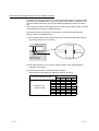
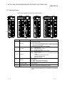
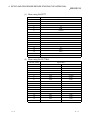
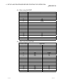
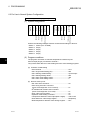
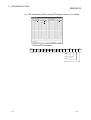
4.3 Parts Identification
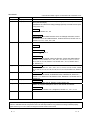
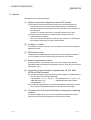
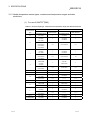
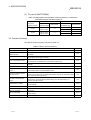
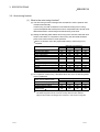
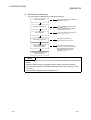
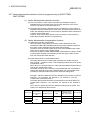
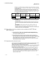
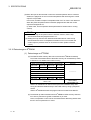
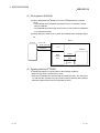
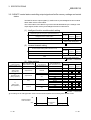
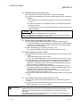
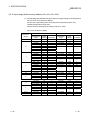
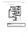
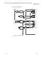
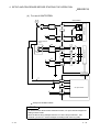
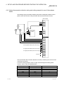
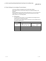
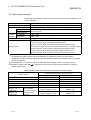
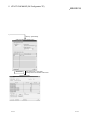
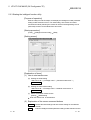
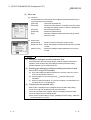
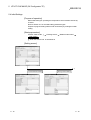
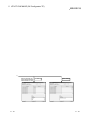
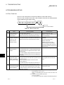
This section explains the names of the Q64TC parts.
1)
3) 1)
3) 1)
3) 1)
3)
2)
2)
4) 2)
2)
4)
NC
NC
6)
6)
5)
5)
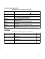
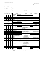
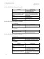
Number
5)
Name
1)
RUN LED
2)
ERR. LED
3)
ALM LED
4)
HBA LED
5)
Terminal block
6)
Cold junction
compensation resistor
5)
5)
5)
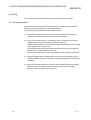
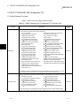
Description
Indicates the operating status of the Q64TCTT(BW).
On: Operating normally.
Off: 5V power is off, watchdog timer error occurred, or CPU stop
error occurred with intelligent function module switches of all
channels set to "CLEAR".
Indicates the error status of the Q64TCTT(BW).
On
: Hardware fault
Flicker : Write data error occurring
Off
: Operating normally.
Indicates the alert status of the Q64TCTT(BW).
On
: Alert occurring
Flicker : Process value (PV) came out of measured temperature
range.
Loop disconnection was detected.
Sensor is not connected.
Off
: Alert not occurring
Indicates the heater disconnection detection status of the
Q64TCTT(BW).
On: Heater disconnection was detected.
Off: Heater disconnection is not detected.
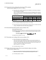
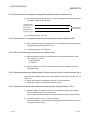
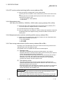
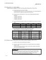
Used for temperature sensor input, transistor output and current
sensor (CT) input.
Used when cold junction compensation is made.
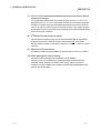
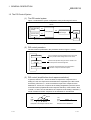
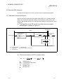
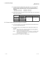
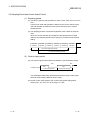
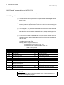
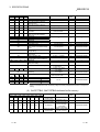
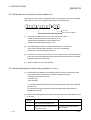
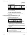
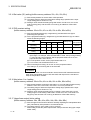
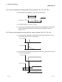
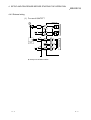
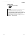
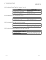
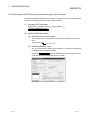
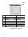
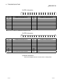
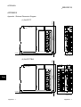
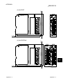
: The terminal block layout varies with the module used.
Respective terminal block layouts are indicated on the following
pages.
4-3
4-3