1
Return to Table of Contents
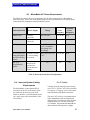
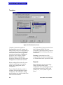
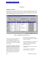
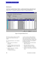
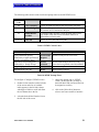
NOTE: Keys only are available in multiples
of ten.
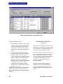
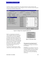
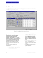
The {XP/AP Keys} column defines the
number of accessory panel keys attached to
an intercom station. The MicroMatrix
automatically detects the number of keys
assigned with two exceptions:
• if non-display XP panels are installed
• if accessory panel configuration is
changed after the panel’s initial
identification.
In both cases select the drop-down menu by
clicking on the desired cell. Then click on
the down arrow in that cell to correctly
define the quantity of expansion and
assignment panels connected to a station.
The XP/AP column displays two numbers
separated by a slash or {None}. A station
with a 10 key expansion panel, a 20 key
expansion panel and an assignment panel is
defined as 30/20 in the XP/AP column.
Select the desired combination of expansion
panel and/or assignment panel keys. With a
single XPL-22 panel installed the {XP/AP
Keys} column should read {20/0}. With a
single AP panel installed the column should
read {0/20}. With one XPL panel and one
AP panel installed the column should read
{20/20}.
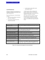
It does not matter whether the expansionpanel keys are 10 key panels (like the XP12) or 20 key panels like the XP-22). For
example, select the number 30 whether there
are three XP-12s installed or one XP-12 and
one XP-22.
WARNING: Make sure the number of
expansion keys shown in <Setup|Hardware
and Labels> matches the number of XP
panel keys connected to the station. If this
isn’t the case, unpredictable results may
occur when using expansion keys.
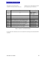
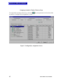
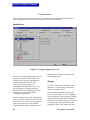
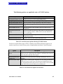
{Talk} and {Listen} labels identify stations,
interfaces, fixed groups, party lines, or
50
controls in the MicroMatrix system.
Generally talk and listen labels are identical
for a given port. When a talk label is entered
for a port, the listen label is given the same
name. Additionally, stations and interfaces
may have split labels; typically split labels
are only used for the IFB Out/Program In
function.
Each port in the system can be given a
{Description}. This description is for user
convenience. The label PGDIR, for
example, might receive a description of
program director.
Checking the {Inward DTMF} column
enables incoming DTMF tone encoding for
a port. That port is then listed on the
<Configure|DTMF Access> screen and
made available for inward DTMF
configuration.
{Card Slot} identifies the matrix card
location for each port. This is for
information purposes and cannot be
modified.
{Matrix Card} identifies the type of matrix
card for a given port.
{Interface} identifies the type of interface (if
any) connected to a port. This is for
information purposes only and cannot be
modified.
Checking the {Party Line} box configures
that port as a party line. Anyone using a port
configured as a party line can hear everyone
else talking on that party line.
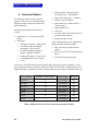
Fixed Groups, Party-Lines, and Controls
{Select One of} in <Setup|Hardware and
Labels> also provides access to the setup of
fixed groups, party lines, and controls.
These functions are given labels and
descriptions and are enabled through these
screens. From an assignment point of view,
these function labels are special and
MicroMatrix User Manual