1
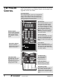
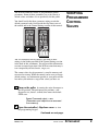
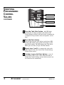
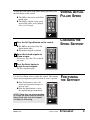
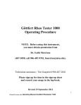
Attachment for
Fenner Control
Option
on Conair Belt
Pullers
WARNING - Reliance on this Manual Could Result in Severe Bodily Injury or Death!
This manual is out-of-date and is provided only for its technical information, data and capacities. Portions of this manual
detailing procedures or precautions in the operation, inspection, maintenance and repair of the product forming the subject
matter of this manual may be inadequate, inaccurate, and/or incomplete and cannot be used, followed, or relied upon.
Contact Conair at [email protected] or 1-800-654-6661 for more current information, warnings, and materials about
more recent product manuals containing warnings, information, precautions, and procedures that may be more adequate
than those contained in this out-of-date manual.
Fenner Control
IME005/1102
THE PULLER
CONTROL
The M-Trim control is an optional operator interface for the belt
puller. Instructions for any optional controls can be found in the
Appendix of this User Guide.
Four-Digit Display
When programming the control, the four-digit display
shows control settings. During normal operation, it
displays either setpoint or actual speed (tach). Both
setpoint and actual speed are expressed as either
linear speed (ft/min or cm/min) or rpm.
Speed Buttons
Use the Set Speed button to enter
and monitor the setpoint speed.
Pressing the Tach button displays
the actual speed. When you select
one of these, the LED in the corner
of the button lights. Either Set
Speed or Tach is active at all times.
NOTE: The actual speed shown is
the average speed. It is updated
once every second.
Numeric Keypad
Use the numeric keypad to
access control parameters,
adjust program settings
and change the setpoint
speed.
Data Entry Buttons
The Clear button deletes the value
showing on the digital display that
you have just entered. The Enter
button to confirms and accepts data
values.
Scroll Buttons
Use the Up and Down scroll
buttons to adjust the active setpoint
displayed on the digital display by
one engineering unit. These buttons
are always enabled.
Programming Keypad
Flip open the bottom
control cover to reveal the
programming keypad.
Two-Digit Display
The two-digit display
shows the active
programming code.
Code Select LEDs
The LED next to the code
lights when that code is
selected. These are not relevant when the Master
Scaling format is used.
Code Select Button
Use this button to enter the
desired programming code.
Programming codes
This table lists the major codes for
you to choose. See the Control
Settings section in the back of this
attachment for a complete listing of
codes.
1
ATTACHMENT
Fenner Control
IME005/1102
The M-Trim control has about 55 programmable control
parameters. Some of these parameters are set by Conair as
default values and others are set specifically for this puller.
You should verify that these parameter settings match the
default parameter codes listed inside the flip-down cover of
the control and in the Control Settings section of this manual.
VERIFYING
PROGRAMMED
CONTROL
VALUES
You also should record any changes you make to these
settings in the blanks provided in the Control Settings section
in the back of this attachment. You will need this information
to return to normal operation if the M-Trim control memory is
ever corrupted by electrical noise, surges, etc.
The current value of each parameter is stored in memory and
recovered on startup. While the control can be reset to factorydefault settings, any information specific to your puller will be
lost unless you maintain a copy of the values you have set.
1
Turn on the puller by turning the main disconnect to
the ON position. The microprocessor performs a selfdiagnostic test (about 2 seconds) then enters the default
STOP state:
Speed Command output = zero
(Parameters and setpoints are recovered
from memory)
2
Open the controller's flip-down cover to view
the programming keypad.
Continued on next page.
IME005/1102
Fenner Control
ATTACHMENT
2
VERIFYING
PROGRAMMED
CONTROL
VALUES
Two-digit display
Code Select button
CONTINUED
Code Select LEDs
Programming codes
3
Press the Code Select button (the LED lights)
and enter the two-digit parameter code. Refer to the
Control Settings section in the back of this attachment for
a complete list of parameter codes, descriptions, and settings.
3
ATTACHMENT
4
Press the Enter button.
5
Repeat steps 3 and 4 to compare the value in the
6
Continue to press the Enter button to view all
The two-digit program code displays in the lower LED
window. The current value for that code displays in the
upper LED window. The LED light on the Code Select
button goes out when you press the Enter button.
upper display to the value listed in the Control Settings
section of this manual.
the parameter codes. If any values differ from what is
listed in the Control Settings section of this manual, contact Conair Service immediately.
Fenner Control
IME005/1102
To view the actual speed of the puller during operation, press
the Tach button on the control.
◆ The LED in the corner of the Tach
VIEWING ACTUAL
PULLER SPEED
button lights.
◆ The Display changes to the actual
speed of the puller, and is updated
every 1 to 2 seconds.
1
Press the Set Speed button on the control.
◆ The LED in the corner of the Set
CHANGING THE
SPEED SETPOINT
Speed button lights.
◆ The numeric keypad is enabled.
2
Enter the desired setpoint in
ft/min or rpm.
If necessary, press the Clear to delete
any errors.
3
Press the Enter button to
accept the new setpoint.
The new setpoint displays.
Use the Up or Down arrow to adjust the setpoint. The setpoint
adjusts by one engineering unit each time an arrow is pressed.
◆ If the Tach button is active, the
FINE-TUNING
THE SETPOINT
actual speed gradually changes to
the new value.
◆ If the Set Speed button is active,
the setpoint changes immediately.
NOTE: These keys are always enabled
to change the active setpoint. Because
they provide only slow scroll speeds,
use them for fine tuning.
IME005/1102
Fenner Control
ATTACHMENT
4
RESTORING
DEFAULT
MEMORY
SETTINGS
WARNING
This procedure restores the M-Trim control to
the factory default settings. Any user-entered
parameters or programming will be erased.
To restore default memory settings:
1
Turn OFF power to the puller.
2
While simultaneously pressing the Clear and the 7
on the numeric keypad, turn the power ON.
◆ The factory default settings are restored. The
M-Trim control performs the power up routine.
RESTORING
USER-SPECIFIC
MEMORY
SETTINGS
Set any user-specific memory settings after you have restored
the default memory settings. Using the Control Settings found
on the tables in Appendix D-1, restore your control to it’s normal operating state:
1
Open the flap at the bottom of the M-Trim control.
2
3
Press the Control Select button.
4
Press the Enter button.
Enter the desired two-digit code number
(from the control settings section located in the back of
this attachment.)
◆ The two-digit code displays in the lower digital
display.
◆ The current parameter value displays in the upper
digital display.
◆ The numeric keypad is enabled.
If necessary, use the numeric keypad to enter a new value.
CAUTION
Press the Enter button within 10 seconds to
accept the new number. Otherwise the parameter reverts to the previous value.
5
ATTACHMENT
Fenner Control
IME005/1102
PID (Proportional, Integral, Differential) tuning is the process
of setting the M-TRIM control algorithm parameters (codes
65-69) to achieve optimum performance. While each puller is
tuned before shipment to optimize performance over the entire
speed range, customers may wish to tune the puller for their
specific operating conditions.
Code Description
Procedure
65
Gain-small numbers
increase the contribution
of the Proportional component. Zero eliminates
the Gain contribution.
1. Set Reset (66) and
Rate (67) to zero.
2. Set Trim Authority
(68) to 100.
3. Reduce the Gain setting until the system
becomes unstable.
4. Increase Gain slightly
to re-stabilize the system.
66
Reset-small numbers increase the contribution of
the Integral component.
Zero eliminates the Reset
contribution.
Decrease the value of
Reset until overshoot
is observed.
Overshoot occurs when
the feedback goes over
the desired setpoint
before settling to the
desired value.
67
Rate-small numbers increase the contribution of
the Derivative component.
Zero eliminates the Rate
contribution.
1. Decrease the value of
Rate until the system
becomes unstable.
2. Increase Rate slightly
to re-stabilize the system.
68
Trim authority-determines
how much of the output is
influenced by Gain, Reset
and Rate, and how much
is determined by feedforward.
Start with Trim Authority
set at 100. If stable operation cannot be achieved,
reduce this parameter
and repeat the tuning
procedure.
69
Rate threshold-sets the
amount of differential
error required before the
Rate term influences the
control output.
If unstable operation
occurs only at very low
feedback frequencies,
slightly increase the
this parameter.
IME005/1102
Fenner Control
ADVANCED
PROCEDURE:
PID TUNING
ATTACHMENT
6
PRODUCT
QUALITY
PROBLEMS
Symptom
Possible cause
Solution
◆ Wall thickness
There are variations in
the speed of the puller.
Check:
❏ The PID Tuning.
❏ If motor brushes are worn.
◆ Diameter fluctu-
There are variations in
the speed of the puller.
fluctuation on the
extrudate.
ation on the extrudate.
7
Look in this section when the extrudate shows annular rings in
the cross-sectional cut of the product.
ATTACHMENT
Fenner Control
Check:
❏ The PID Tuning. See the
section entitled, ADVANCED
PROCEDURE: PID TUNING in this
attachment.
.
❏ If motor brushes are worn.
IME005/1102
OPERATION
PROBLEMS
Look in this section when the control or motor is not working
properly.
Symptom
Possible cause
Solution
◆ Controller
RAM failed.
Contact Conair service.
◆ Controller
PROM checksum comparison failed.
Contact Conair service.
stopped during
power-up PROM
❐.❐
❐.❐
❐.❐
❐’ distest. ‘❐
plays in the digital
display.
stopped during
power-up RAM
test. A number displays in the digital
display.
◆ Motor does not
Check programming code 53.
See M-TRIM USER MANUAL,
DIAGNOSTICS.
stop.
◆ Motor does not
Check programming code 53.
See M-TRIM USER MANUAL,
DIAGNOSTICS.
run.
Fenner Control
IME005/1102
ATTACHMENT
8
Look in this section when the control or motor is not working
properly.
Symptom
OPERATION
PROBLEMS
Possible cause Solution
◆ Motor runs at
Check programming code 53.
See M-TRIM USER MANUAL,
DIAGNOSTICS.
wrong speed.
◆ Motor at correct Maximum rpm incorrect- Check programming code 11.
(set) speed, but not
fast enough for the
extrusion line.
See M-TRIM USER MANUAL,
DIAGNOSTICS.
ly set.
◆ Motor at correct Minimum rpm is set
Check programming code 10.
See the M-TRIM USER MANUAL,
DIAGNOSTICS.
◆ Motor seems
Check PID tuning. See the
section entitled, ADVANCED
PROCEDURE: PID TUNING in this
attachment.
(set) speed, but not
slow enough of the
extrusion line.
incorrectly.
unstable.
◆ Tach reads
See item 8, M-TRIM USER
MANUAL, DIAGNOSTICS.
incorrectly.
◆ Display shows
---1, ---2, or ---3.
Electrical noise is reaching controller.
Check control parameters
against desired values. If values have changed, restore the
original settings. See
RESTORING MEMORY SETTINGS
in this section.
9
ATTACHMENT
Fenner Control
IME005/1102
This table shows the settings for each control parameter set at
the factory. The parameters are set either to the default setting,
or to a setting specific to your requirements (Customer column). If you change any value, record it in this column. Keep
these values up-to-date so you can easily restore your puller to
normal operation if the memory is corrupted.
Code Parameter
Setpoint Control
01
Primary Setpoint 1
02
Primary Setpoint 2
03
Secondary Setpoint 1
04
Secondary Setpoint 2
05
Jog Setpoint
06
Output Setpoint
Alarms and Limits
10
Minimum Limit
11
Maximum Limit
12
Low Alarm
13
High Alarm
14
Error Alarm 1, ramped
15
Error Alarm 2, scaled
Acceleration and Deceleration
16
Acceleration time
17
Deceleration time
Phase Control
18
Lag Pulse Limit
19
Lead Pulse Limit
Scaling
20
Engineering units
21
22
23
(primary setpoint)
Engineering units
(secondary setpoint)
Engineering units
(primary display)
Engineering units
(secondary display)
Phase Control
29
Recovery multiplier
Scaling
30
PPR (external
31
32
33
34
35
reference input)
PPR (feedback input)
PPR (auxiliary input)
Max RPM (external
refer. input: primary mode)
Max RPM (feedback:
primary mode)
Max RPM (auxiliary
input: primary mode)
Fenner Control
Range
Default Customer
0000-9999
0000-9999
0000-9999
0000-9999
0000-9999
0000-9999
CONTROL
SETTINGS
If the controller's memory is
corrupted by electrical noise
or static, you may need to
reset the control parameters.
0000-9999
0000-9999
0000-9999
0000-9999
0000-9999
0000-9999
000.0-600.0
000.0-600.0
0-9999
0-9999
000.0-9999
000.0-9999
000.0-9999
000.0-9999
0-100
1-9999
1-9999
1-9999
1-9999
60
1-9999
1750
1-9999
Continued on next page.
IME005/1102
ATTACHMENT
10
CONTROL
SETTINGS
CONTINUED
11
ATTACHMENT
Code Parameter
Range
Max RPM (external refer.
1-9999
input: secondary mode)
37
Max RPM (feedback:
1-9999
secondary mode)
38
Max RPM (auxiliary input: 1-9999
secondary mode)
Scaling Format Selection and Control
60
Output format
1-2
61
Primary scaling mode
0-3
62
Secondary scaling mode
0-3
63
Primary display mode
1-2
64
Secondary display mode
1-2
Tuning
65
Gain
0-9999
66
Reset (integral)
0-9999
67
Rate (derivative)
0-9999
68
Trim authority
0-100
69
Rate threshold
0-100
Serial Communications
70
Device addresses
1-32
71
Baud rate
1-6
72
Character format
1-3
73
Control mask
0-255
Alarms and Limits
74
Zero speed logic
0-1
Scaling Format Selection and Control
75
Primary mode
0-9999
positive offset
76
Primary mode
0-9999
negative offset
77
Secondary mode
0-9999
positive offset
78
Secondary mode
0-9999
negative offset
Setpoint Control
79
Setpoint mask
0-2
Analog Input/Output
80
Analog output
0-99
function select
81
Analog output range
0-9999
82
Analog output zero
0-2048
83
Analog output span
2048-4095
84
Analog input
0-7
function select
85
Analog input zero
0-2048
86
Analog input span
2048-4095
Default Customer
36
IME005/1102
01
01
Fenner Control