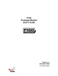
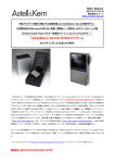
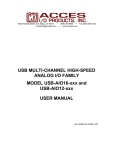
1
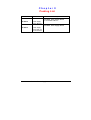
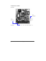
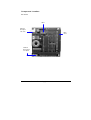
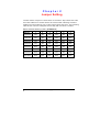
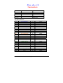
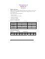
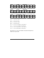
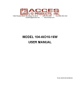
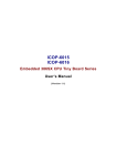
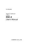
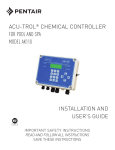
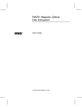
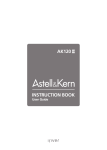
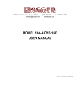
EX-90070/90072
Power Supply AC/DC PC/104 Module
Power Supply DC/DC + DIO PC/104 Module
User’s Manual
(Version 3.2)
Table of Contents
Chapter 0
Packing List
1
Chapter 1
Specifications
2
Chapter 2
Jumper Settings
6
Chapter 3
Connectors
7
Chapter 4
Digital I/O
8
Warranty
10
iii
Chapter 0
Packing List
Function
EX-90070
Function
Power Supply
AC/DC Module
Package
z EX-90070 Power Supply Module
z 3 Pin extend cable x 1
z EX-90072 Power Supply Module
EX-90072
1
Power Supply
DC/DC with 24Bit DIO Module
PC/104 Power Supply User's Manual
Chapter 1
Specifications
Features
EX-90070
Power
Input voltage range : 90 ~ 264 VAC
Output voltage :
+5 VDC @ 2A,
-5 VDC @ 0.2 A,
+12 VDC @ 1 A,
-12 VDC @ 0.3 A
Input frequency : 47 ~ 63 Hz
Inrush current cold : 20A @ 110VAC, 40A @ 220 VAC
Hold-up time : 16 ms
Raise time: 500 ms
Overload protection: power limit
Short protection : auto-recovery
MOSFET design
Built-in line filter
Meets FCC, CE, TÜV
Meets UL478 and CS
Fast type FUSE 2A/250V
Connector
3-pin AC input
6-pin DC output (-5V,-12V,+12V,GND,GND,+5V)
Bus Interface
PC/104 standard compliant
Dimensions
90 (L) x 96 (W) mm.
Weight
90 g
Operating
Temperature
0 ~ +60 °C
2
PC/104 Power Supply User's Manual
Features
EX-90072
Digital I/O
24 bit digital I/O lines (1 group)
Group emulates a 8225 PPI mode 0
Buffered circuits for higher driving capacity than 8255
Output status read back
Pin-compatible with OPTO-22 I/O module racks
Transfer rate: 300 KB/sec. (typical)
Digital output:Logic level 0: 0.5 V max. @ 24 mA sink
Logic level 1: 2.0 V min. @ 15 mA source
Digital input:
Logic level 0: 0.8 V max.
Logic level 1: 2.0 V min.
Input Voltage: +8V ~ +48V DC
Power
Output Voltage: 5V DC / 3A
Over load protection
Over heat protection
Converted frequency: 52 KHz
Converted effect: Over 80%
Suitable for auto / truck system
Bus Interface
PC/104 standard compliant
Dimensions
90 (L) x 96 (W) mm.
Weight
110 g
Operating
Temperature
-20 ~ +60 °C
3
PC/104 Power Supply User's Manual
Component Location
EX-90070
CN1
AC Input
L
CN4
DC Output
N
G
EX-90071
-5v / -12v / +12v / GND / GND / +5v
4
PC/104 Power Supply User's Manual
Component Location
EX-90072
SW1
CONT4
DC Input
+8v~+48
DIO
Cont
CONT5
DC Output
+5v @ 3A
5
PC/104 Power Supply User's Manual
Chapter 2
Jumper Setting
The EX-90072 occupies 8 consecutive I/O locations. Dip-switch SW1 sets
the base address for the EX-90072. Be careful when selecting the base
address as some settings can conflict with existing PC ports. The following
table shows common examples that usually will not cause a conflict.
Base Address Setting (SW1) (EX-90072)
Address
1
2
3
4
5
6
000-00Fh
ON
ON
ON
ON
ON
ON
010-01Fh
ON
ON
ON
ON
ON
OFF
020-02Fh
ON
ON
ON
ON
OFF
ON
030-03Fh
ON
ON
ON
ON
OFF
OFF
200-20Fh
OFF
ON
ON
ON
ON
ON
210-21Fh
OFF
ON
ON
ON
ON
OFF
300-30Fh *
OFF
OFF
ON
ON
ON
ON
3F0-3FFh
OFF
OFF
OFF
OFF
OFF
OFF
6
PC/104 Power Supply User's Manual
Chapter 3
Connectors
Connector
CONT1
EX-90070
EX-90072
AC Input
CONT2
CONT3
CONT4
DC Output
CONT5
EX-90072
PIN
1
3
5
7
9
11
13
15
17
19
21
23
25
27
29
31
33
35
37
39
41
43
45
47
49
7
CONT3
ASSIGNMENT
AIO23/PARTC
AIO22/PARTC
AIO21/PARTC
AIO20/PARTC
AIO19/PARTC
AIO18/PARTC
AIO17/PARTC
AIO16/PARTC
AIO15/PARTB
AIO14/PARTB
AIO13/PARTB
AIO12/PARTB
AIO11/PARTB
AIO10/PARTB
AIO9/PARTB
AIO8/PARTB
AIO7/PARTA
AIO6/PARTA
AIO5/PARTA
AIO4/PARTA
AIO3/PARTA
AIO2/PARTA
AIO1/PARTA
AIO0/PARTA
VCC
Digital I/O Group 1
8-48VDC Input
5VDC Output
PIN
2
4
6
8
10
12
14
16
18
20
22
24
26
28
30
32
34
36
38
40
42
44
46
48
50
ASSIGNMENT
GND
GND
GND
GND
GND
GND
GND
GND
GND
GND
GND
GND
GND
GND
GND
GND
GND
GND
GND
GND
GND
GND
GND
GND
GND
PC/104 Power Supply User's Manual
Chapter 4
Digital I/O
(EX-90072)
Mode 0 Operation
Mode 0 operation provides simple input and output operation for each of the
three ports. No handshaking is required, data is simply written to or read
from a specific port.
Mode 0 Basic Functional Definitions:
- Three 8-bit ports
- Any port can be input or output
- Outputs are latched
- Inputs are not latched
I/O port Assignments
Location
Write
Read
BASE+0
A0
A0
BASE+1
B0
B0
BASE+2
C0
C0
BASE+3
Mode Register for A0,B0,C0
N/A
8255 Data Registers
Base+0
8
Port A0
(read/write)
Bit
7
6
5
4
3
2
1
0
Value
PA07
PA06
PA05
PA04
PA03
PA02
PA01
PA00
PC/104 Power Supply User's Manual
Base+1
Port B0
(read/write)
Bit
7
6
5
4
3
2
1
0
Value
PB07
PB06
PB05
PB04
PB03
PB02
PB01
PB00
Base+2
Port C0
(read/write)
Bit
7
6
5
4
3
2
1
0
Value
PC07
PC06
PC05
PC04
PC03
PC02
PC01
PC00
Base+3
Port A0,B0,C0
(write)
Bit
7
6
5
4
3
2
1
0
Value
1
0
0
PA0
PCH
0
PB0
PCL
PA0 = 0 => Port A0 is output
PA0 = 1 => Port A0 is input
PB0 = 0 => Port B0 is output
PB0 = 1 => Port B0 is input
PCL = 0 => Port C0 Low Nibble is output (Bit0-3)
PCL = 1 => Port C0 Low Nibble is input (Bit0-3)
PCH =0 => Port C0 High Nibble is output (Bit4-7)
PCH =1 => Port C0 High Nibble is input (Bit4-7)
After power-on or reset of the module the A0, B0 and C0 ports are
default set to input mode.
9
PC/104 Power Supply User's Manual
Warranty
This product is warranted to be in good working order for a period of one
year from the date of purchase. Should this product fail to be in good
working orderat any time during this period, we will, at our option, replace or
repair it at noadditional charge except as set forth in the following terms.
This warranty doesnot apply to products damaged by misuse, modifications,
accident or disaster. Vendor assumes no liability for any damages, lost
profits, lost savings or anyother incidental or consequential damage
resulting from the use, misuse of, orinability to use this product. Vendor will
not be liable for any claim made by anyother related party. Return
authorization must be obtained from the vendor before returned merchandise will be accepted. Authorization can be obtained by calling or faxing the
vendor and requesting a Return Merchandise Authorization (RMA) number.
Returned goods should always be accompanied by a clear problem
description.
10
PC/104 Power Supply User's Manual