1
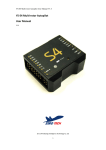
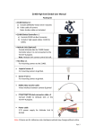
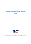
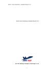
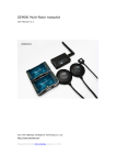
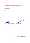
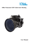
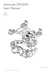
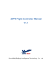
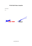
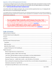
ZERO Gimbal Z1400 User Manual www.zerouav.com SAFETY INFORMATION Thank you for purchasing our product. Please carefully read and observe the following safety information before using this product. Our company assumes no liability or responsibility for equipment damage or for injury caused by ignoring the following safety information. Do not modify the gimbal or related structure. This may impact the function of the gimbal or in serious cases, destroy the electronics. Before leaving the factory, the center of gravity of the Gimbal Z1400 is adjusted for the Panasonic GH3 camera with a Lumix G 14mm f/2.5 lens. If a different camera is used, it must be adjusted. If not, the gimbal does not need to be adjusted; all that is necessary is that the camera be attached. The gimbal must be operated with a load equivalent to a camera with its center of gravity regulated to the best position. (The camera should remain static and balanced when deployed at any angle. If the gimbal is not loaded it will shake uncontrollably and may burn out the motors or electronics. The Gimbal must be matched by a flight control system designed by our company and should be used and commissioned in an open and safe site and in normal weather conditions. Before energizing the gimbal should be manually rotated to ensure it is free from obstructions which may destroy the motors. Do not forcibly operate this equipment. If there is any doubt about its correct operation or if it does not move freely, please contact our technical staff or sales department. © The information in this user manual is protected by copyright, without prior written permission of our company, such information or data shall not be photocopied or duplicated in any way. The Company reserves the right of final interpretation of this notebook and relevant information. Contents 1 General Product Information ................................................................................................................................................................................ 1 2 Product Inventory................................................................................................................................................................................................. 3 3 Gimbal wiring ....................................................................................................................................................................................................... 5 3.1 Definition Of Gimbal Controller Interface ..................................................................................................................................................... 6 3.2 Independent Gimbal Operation ................................................................................................................................................................... 6 3.3 Non-independent gimbal operation ............................................................................................................................................................. 8 4 Installation of camera........................................................................................................................................................................................... 9 4.1 Installation Steps (taking Panasonic GH3 as an example) .......................................................................................................................... 9 4.2 Adjustment of Center of Gravity ................................................................................................................................................................ 11 5 Gimbal Working modes ..................................................................................................................................................................................... 12 6 Setting up the Remote control transmitter ......................................................................................................................................................... 13 7 Gimbal Operation............................................................................................................................................................................................... 14 7.1 Check before operation ............................................................................................................................................................................. 14 7.2 AaOperational steps .................................................................................................................................................................................. 15 8 APPENDIX ........................................................................................................................................................................................................ 18 8.1 Resetting the gimbal Gyro ......................................................................................................................................................................... 18 8.2 Upgrading the firmware ............................................................................................................................................................................. 19 8.3 Adjusting parameters ................................................................................................................................................................................ 21 8.4 SPECIFICATION....................................................................................................................................................................................... 24 8.5 Zero UAV Technical support and videos ................................................................................................................................................... 27 1 GENERAL PRODUCT INFORMATION The Z1400 gimbal is a three-axis brushless motor direct drive gimbal researched and developed by Zero UAV especially for professional photographic applications. The three axes are each driven by a Brushless Motor with high accuracy and a high speed driver module developed by us. When used with our Multi-Rotor Autopilot, the Zero UAV Gemini the gimbal has super strong stability, super high accuracy and super sensitive response. GH3/4/α7 professional 3-axis motor driving gimbal with high stability Can be operated independently and is compatible with other mobile gimbals Perfectly matches Zero UAV Multi-rotor flight control systems 3-axis rotation angle without limit High precision IMU module 360°panorama shooting function Rotation speed of all 3-axes is controllable Supports various lens options Expandable wireless remote focus following module Simple access to CF card(memory card) Can be further upgraded and expanded to carry RED and other cameras Zero UAV (Beijing) Intelligent Technology Co., Ltd. 1 Gimbal direction Yaw axis (360° continuous rotation) Damper ball Gimbal retention clip Motor driver 1 IMU module Motor driver 3 Roll axis (360° continuous rotation) Pendant above camera Pendant below camera Motor driver 2 Tile axis (360° continuous rotation) Figure 1 gimbal: Schematic diagram Zero UAV (Beijing) Intelligent Technology Co., Ltd. 2 2 PRODUCT INVENTORY Product Instruction Built-in Zero professional brushless motor speed controllers, integrated camera video Gimbal Z1400 output cable, shutter release tec. HDMI lead for GH3 / GH4 camera Links between camera HDMI port and gimbal HDMI video output. AV video extension cord Extends camera video output to connect video equipment. Gimbal CONTROLLER Gimbal controller connects the Zero Data Bus from the flight controller to the gimbal. Receiver cable Connect to S-BUS receiver (only one S-BUS cable needed). Power cord Supplies power for gimbal controller and gimbal. USB cable Connects PC to gimbal controller to adjust parameters and upgrade firmware. PTZ1 / PTZ2 / PTZ3 connecting The gimbal controller communicates with GEMINI dual or GEMINI individual units vis cable this connecting cable. Zero UAV (Beijing) Intelligent Technology Co., Ltd. 3 Hot-shoe Assists fixing gimbal to camera. 2×8PT socket head cap screw with Fix camera on pendant above gimbal. flat head 3×8PT socket head cap screw with Fix camera on pendant above gimbal. flat head 4 × 12PT socket head cap screw Fix camera on pendant below gimbal. with flat head 1/4×10 BS screws Fix camera on pendant below gimbal. 3×6 socket head cap screw with Regulating weight. round head 3×8 socket head cap screw with Regulating weight. round head Zero UAV (Beijing) Intelligent Technology Co., Ltd. 4 3 GIMBAL WIRING Please carefully read and observe the following instructions before wiring the unit to avoid serious personal injury or equipment damage. All connections must be in strict accordance with the wiring diagram, otherwise the equipment will not perform normally and may even be damaged. Use a 6 cell (6S) Lithium Polymer (LIPO) battery to supply power to the gimbal. The standard power supply module supplied, must be used to supply power to the gimbal controller and flight controller, if not, the equipment may be burnt out. When installing, please note that arrow printed on the gimbal must correspond to the forward direction of the aircraft. If this form of installation is not possible, parameter regulating software may be used to change the deviation angle between the forward direction of the gimbal and the aircraft head direction. Zero UAV (Beijing) Intelligent Technology Co., Ltd. 5 3.1 Definition Of Gimbal Controller Interface Figure 2 definition of gimbal controller interface 3.2 Independent Gimbal Operation If you need to use the gimbal independently (without being mounted on an aircraft), a Gemini or individual GEMINI-M/GEMINI-S flight control unit must still be used with the Z2000 Gimbal. After connecting the gimbal to the flight controller it will provide the gimbal with posture data corresponding its three-dimensional position. The arrow on the gimbal needs to keep consistency with the arrow on the Gemini flight control. Zero UAV (Beijing) Intelligent Technology Co., Ltd. 6 5.7V PSU S-BUS receiver AV video 6S Li battery clock line (CLOCK, green and black line) data line(DATA green line) power(black and red line) GIMBAL video(yellow and black line) Figure 3 Connection diagram for independent gimbal operation Zero UAV (Beijing) Intelligent Technology Co., Ltd. 7 3.3 NON-INDEPENDENT GIMBAL OPERATION The Gemini auto-pilot or individual GEMINI-M/GEMINI-S flight control units can provide the Z2000 gimbal with high precision positional information and will guarantee the normal flight of the aircraft. . The arrow on the gimbal needs to keep consistency with the arrow on the Gemini flight control. S-BUS receiver 5.7V PSU S-BUS receiver AV video 6S Li battery clock line (CLOCK, green and black line) data line(DATA green line) power(black and red line) GIMBAL video(yellow and black line) Figure 4 Connection diagram for non-independent gimbal operation Zero UAV (Beijing) Intelligent Technology Co., Ltd. 8 4 INSTALLATION OF CAMERA 4.1 INSTALLATION STEPS (TAKING PANASONIC GH3 AS AN EXAMPLE) Step1, install the hot shoe to the slot of camera. slot hot shoe Figure 5 push the hot shoe into the slot Step2, fix the camera to the upper pendant by screws in figure Zero UAV (Beijing) Intelligent Technology Co., Ltd. 9 camera upper pendant 2×8PT screw (2×10PT screw for old version) 3×8PT screw (3×6PT screw for old version) Figure 6 fixing with upper pendant Step3, fix the camera to the lower pendant by screws in figure British system screw 1/4×10 4×12PT screw camera lower pendant Figure 7 fixing with camera lower pendant Step4, use standard HDMI video switch line to Gimbal video port and camera video output port Note: Zero UAV (Beijing) Intelligent Technology Co., Ltd. 10 Take out the peripherals of the camera(such as filter and hood),camera center of gravity need to be adjusted again by customer if other peripherals need to be added. Check the installation of battery ,memory card and focus; shutter speed need to be set to 1/120s,otherwise may lead to jelly or jitter. 4.2 ADJUSTMENT OF CENTER OF GRAVITY 1. Before leaving the factory, the center of gravity of the Z1400 Gimbal is pre-adjusted for the Panasonic GH3 camera with the Lumix G 14mm f/2.5 lens. Re-adjustment is required when changing camera or lens. If the camera or lens is not changed, then there is no need to modify the mechanical structure or the installation mode of the gimbal. All that is needed is to fix the camera. 2. The gimbal must be equipped with a camera load, and its center of gravity must be adjusted to the best position (the camera should stop and remain static when deployed at any angle. Do not energize the gimbal under a no-load condition, this would lead to the gimbal jittering, and might burn out the motors or the controller. A video tutorial demonstrating camera adjustment can be seen at: http://v.youku.com/v_show/id_XODkwMjc5ODky.html Zero UAV (Beijing) Intelligent Technology Co., Ltd. 11 5 GIMBAL WORKING MODES This equipment supports two working modes: gimbal working mode and remote control rate mode: Position Gimbal working mode CH5 1st Non-direction lock mode, i.e. the direction of the gimbal does not change along Remote control rate mode CH6 Slow gimbal movement speed. position with the change of direction of the aircraft. Direction follow mode without allowance, i.e. the gimbal direction and aircraft 2nd Median gimbal movement direction track each other exactly, the size of the angle can be regulated by the position speed. transmitter sticks. 3rd Direction follow mode with 5º allowance, i.e. the gimbal only follows the aircraft Fast gimbal movement speed. position direction when the angle between them is greater than 5°. Zero UAV (Beijing) Intelligent Technology Co., Ltd. 12 6 SETTING UP THE REMOTE CONTROL TRANSMITTER Your RC transmitter (TX) must use “fixed-wing mode”, do not set up any mixes. If using a Futaba TX, none of the channels should be reversed. JR, Tiandifei and possibly other remote controls should have all channels reversed. Video refer to: http://www.tudou.com/programs/view/e1ai526Mbt4/. Gimbal remote controller channel definition Channel Definition Description CH1 Aileron channel Gimbal roll control CH2 Elevator channel Gimbal pitch control CH3 Throttle channel CH4 direction channel CH5 Add force to the gimbal when pushing up,decrease force to the gimbal when pulling down Gimbal direction control position 1 No direction follow position 2 Direction follow lock position 3 Direction follow with 5° lag Zero UAV (Beijing) Intelligent Technology Co., Ltd. 13 CH6 position 1 Low speed position 2 Mid range position 3 Fast NOTE: method to view remote controller channel: power on remote controller→MOL→SERVO. Gimbal remote controller setting step 1. Set a 3-position switch to CH5,controlling gimbal work mode; set a 3-position to CH6,adjusting gimbal revolving speed. 2. Retractable landing gear control: If the signal wire of retractable control module is plugged in an empty channel of gimbal receiver, then correspond channel is set into 2-position switch or knob switch, for controlling the retractable landing gear. 3. CH8 is set to a 2-position switch, controlling the shooting and recording. 7 GIMBAL OPERATION 7.1 CHECK BEFORE OPERATION 1. Check the installation of parts is accurate and the wiring firmly fastened. Zero UAV (Beijing) Intelligent Technology Co., Ltd. 14 2. Inspect the power supply to the gimbal, if all gimbal indicators light up, successful energizing is indicated. 3. Check the center of gravity of the camera: it should be stable and centered i.e. when unpowered, move the camera to any position, it should stay static in its current position after release. 4. Check that all screws are tightened to avoid instability and shaking. 5. Check that channel settings on the transmitter are correct. 7.2 AAOPERATIONAL STEPS 1. Supply power to the gimbal (When using the spark prevention plug it must be inserted at the bottom, otherwise the gimbal will be in an abnormal power supply state). 2. Switch on the transmitter 3. Self-inspection of gimbal: by hand, rotate the camera in at least one complete circle (360°) along all three axes, i.e. make sure it freely and continuously rotates in pitch, roll and yaw (pan) directions. NOTE: The gimbal must be allowed to carry out its self-inspection every time it switched on to ensure that it functions correctly. Zero UAV (Beijing) Intelligent Technology Co., Ltd. 15 Figure 8 Self-inspection 4. Push the throttle on the gimbal remote control to its maximum level, now the gimbal will start stabilization. Now slightly push the gimbal to check whether it recovers, and whether it stops stabilization when the throttle is reduced to minimum. 5. If the gimbal remote control sends a roll, tilt or pan signal, then the gimbal should respond accordingly. 6. Other operations: making the gimbal automatically follow the direction of aircraft—CH5 1. Initiate the stabilization process on your gimbal (i.e. push the throttle stick to its maximum level) 2. Rapidly toggle CH5 three times, the gimbal will turn to face the same direction as the front of the aircraft. Panoramic Scanning—CH6: 1. Initiate the gimbal motor stabilization process (i.e. push the throttle to its maximum level); 2. Rapidly toggle CH6 three times to start the panorama shooting function. When carrying out Zero UAV (Beijing) Intelligent Technology Co., Ltd. panorama scanning , 16 the gimbal will automatically sequence the following functions: keep level to the ground , tilt down 30º, tilt down 60º, tilt down 90º (vertical), repeating each “layer” four times in total ( Respectively: 12 photos for the first 3 layers, 1 photo for the last layer making 37 copies in total ). 3. After completion of the panoramic scan, the gimbal will automatically return to level (when shooting the last photo, the gimbal will have moved vertically downwards). Point camera down 90º (vertical)—CH7: Rapidly toggle CH7 three times to make the camera point immediately down. NOTE: When the gimbal cannot detect the signal from the gimbal remote control (if it is out of range or the transmitter is broken etc.) the gimbal will retain its state before communication was lost. If the gimbal has shifted or been moved then the stick operation to reset the gyro should be carried out. Check parts or settings that may cause “jello”: 1 If there is any damage or ageing on the damping ball, please replace it immediately. 2 Check the aircraft does not vibrate excessively and that that the gimbal fixing is stable as this could cause destructive resonance. 3 The shutter speed should be set at 1/120s to avoid the jello effect. Zero UAV (Beijing) Intelligent Technology Co., Ltd. 17 8 APPENDIX 8.1 RESETTING THE GIMBAL GYRO If there is a large change in temperature (extreme cold /extreme hot), then there may be some gyro drift, causing the gimbal to slowly rotate without any signal input. If so the gyro should be reset. Taking a FUTABA RC transmitter as an example, place the gimbal on a fully static table or on the ground, bring the throttle to the bottom. Now move the gimbal motors and let them stop in any position. The gimbal should remain fully static. Now start the gyro reset operation. Here we are using the Japanese stick-mode as an example (Mode 3) Pull the rudder to the left and elevator to the bottom and the aileron to the right and throttle to the bottom as in the figure (move the sticks in a “/\"-shape if your stick-mode is Japanese or American style, move the sticks in a “V”- shape if your stick-mode is Chinese or European style), then release the sticks after holding for a half-second. This will automatically start to reset the gyro (keep the camera in an absolutely static state during the gyro reset process) After 3 seconds, the gyro reset will be completed. Now manually keep the camera upright and gently push the throttle to its maximum value to initiate stabilisation. Zero UAV (Beijing) Intelligent Technology Co., Ltd. 18 Figure 9 Resetting the gimbal Gyro ((example with Japanese Hand)) 8.2 UPGRADING THE FIRMWARE NOTE: The sales or technical department of Zero-UAV should be contacted to find out if a firmware upgrade is needed. Step 1, Installation of USB driver.. (1) Download the USB driver installation program from www.zerouav.com or the official Zero UAV QQ forum. (2) Install the USB driver in accordance with the instructions on the interface. Restart the PC after installation. (3) Connect one USB connection to the COM port on the gimbal controller (white wire is up); connect the other USB connection to the PC. Step 2, Upgrade gimbal firmware (4) Download the firmware upgrade program from www.zerouav.com or from the official Zero UAV QQ forum. Zero UAV (Beijing) Intelligent Technology Co., Ltd. 19 (5) Shut down the power supply of gimbal controller. (6) Open the “AP firmware upgrade” program, click “Upgrade”, then carry out the following 4 steps. 1. Select serial port: (My PC: Properties: Device: Manager: Port) 2. Click “Open COM” 3. Click “Open” to select firmware from current file location on PC. 4. Restart gimbal controller begin upgrade process . Figure 10 Upgrade gimbal firmware (for reference) Zero UAV (Beijing) Intelligent Technology Co., Ltd. 20 (7) When the words "Upgrade complete, please close this window!" appear, shutdown power to complete the upgrade operation. NOTE: Contact Zero UAV sales or tech. support to provide the required firmware upgrade program if you are unable to download it from the site. If the software does not start upgrading when you apply power, close the program and re-connect the serial port to start again. 8.3 ADJUSTING PARAMETERS NOTE: All parameter adjustments have been completed before any Z series gimbals leave the factory, they can be used immediately. If you need to adjust any parameters you should first consult Zero UAV tech. or sales. Improper parameter setting may lead to abnormal operation or even damage the gimbal. Zero UAV (Beijing) Intelligent Technology Co., Ltd. 21 Download gimbal configuration software from www.zerouav.com or the official Zero UAV QQ Forum. Energize the gimbal, open the software and carry out the following 4 steps: 2. Click “Open COM”, for dynamic data display. 1. Select serial port: (My PC: Properties: Device: Manager: Port, choose current port) 3. Click “Read” to acquire current gimbal parameters. 4. Click “Save” to upload data or modifiled parameters to gimbal controller. Figure 11 Adjusting parameters (for reference) Zero UAV (Beijing) Intelligent Technology Co., Ltd. 22 Stick positions on RC transmitter: when the sticks are released these values should reflect the neutral stick position. If not gimbal should be restarted after the transmitter is switched on (the gimbal will automatically record the neutral positions). This is the angle rate of the pitch, roll and yaw axes. The range is between 0.01 and 0.1 when it is static. If the gimbal moves and the value does not change, then the gimbal bus is damaged or not connected properly. The position reached by the motors on each axis, the value is an integer between 0-8191. The value will not change when the gimbal is static. If the gimbal moves the value should increase or decrease. If not, the gimbal bus is damaged or not connected properly. The position when the gimbal is connected via PTZ1/PTZ2/PTZ3. When the flight controller is tilted by hand this value should change to the corresponding posture angle. If not, the gimbal bus is damaged or not connected properly. The serial number and the firmware version number of the gimbal controller. The PID values for YAW, ROLL and PTICH have been preset. No further adjustment is needed. There are 4 choices for the deviation angle between the forward direction of the gimbal and the head of the aircraft: the default value is 0 (matched). There are 2 transmitter types. The default value is shown (Gimbal Controlled by SBUS Transmitter). There are 2 gimbal installation styles shown. The default value is Normal (Gimbal Below Platform). Figure 12 Data and parameters NOTE: After modifying data or parameters, “Save” should be clicked several times to activate the settings. Now click “Read” to check the settings are correct. If the angle of deviation between the gimbal and aircraft head direction has been modified "the settings should be activated as follows: Zero UAV (Beijing) Intelligent Technology Co., Ltd. 23 1. Align the camera, make the camera lens consistent with the direction of gimbal, and then click "Test mode". 2. Initialize stabilization (i.e. push the throttle to its maximum level); If the gimbal now automatically rotates to the direction of aircraft head, then the setting will come into effect. If not you should reset after clicking "Default Parameters" and "Read". 3. After inspection, click “Normal Mode” to revert to normal status. 8.4 SPECIFICATION Platforms hand-held, vehicle-mounted, aircraft, and others built-in HDMI-to-AV mode, real-time output of Video signal , build-in Built-in functions IMU General Features Non-direction lock mode ,follow mode without allowance and follow Working modes mode with 5º allowance Size Horizontal diameter 280mm,height 340mm Weight 1.4kg (without camera) , 2KG (with camera) Zero UAV (Beijing) Intelligent Technology Co., Ltd. 24 Pan:±360°Continuous rotation extended stable range Tilt:360°Continuous rotation Roll:±30°Continuous rotation (adjustable ±360°Continuous rotation) Mechanical Rotation range Three axis ±360°Continuous rotation Characteristics angle control precision ±0.03° (Pan): ±145°/s Maximum speed (Tilt): ±145°/s (Roll): ±145°/s quiescent current: 200mA (@24V) Electronic working current Characteristics Peripheral dynamic current:500mA (@24V) Locked current: 4A (@24V) Operating Temperature -10°C~50°C Gimbal input power 6S @ 22.2V Support camera Panasonic GH3/GH4 Zero UAV (Beijing) Intelligent Technology Co., Ltd. 25 Sony A7(camera Shutter control is not supported) products Lumix G 14mm f/2.5 Lumix G 20mm/F1.7 Support lens Panasonic LEICA 25/1.4 OLYMPUS M.ZUIKO DIGITAL ED12mm f/2.0 etc. Parameter Configuration Software Windows XP SP3; Windows 7; Windows 8 Installation Environment S-BUS receiver Control Requirement Standard receiver (matched with conversion module ) Zero UAV (Beijing) Intelligent Technology Co., Ltd. 26 8.5 ZERO UAV TECHNICAL SUPPORT AND VIDEOS Setting up RC TX : http://www.tudou.com/programs/view/e1ai526Mbt4/ Adjusting camera center of gravity : http://v.youku.com/v_show/id_XODkwMjc5ODky.html Zero UAV Z1400 (GH3/GH4)3-axis gimbal aerial photography :http://v.youku.com/v_show/id_XNTgxNzY4NTg0.html Zero UAV QQ groups:168451730(group 1),228669705(group 2),242018689(group 3), 53371874(group 4) Zero UAV Official website:http://www.zerouav.com Zero UAV Telephone:010-82825376 Relevant technical files can be downloaded from the Zero UAV official website or from Zero UAV QQ groups. Zero UAV (Beijing) Intelligent Technology Co., Ltd. 27