1
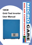
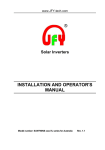
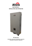
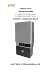
Grid-Tied Inverter
User Manual
Models: 3000 Watt
Included
1 x 3Kw GRID TIED Inverter
2 x MC4 Connector Sets
4 x White 2-Way Expansion Plugs
4 x Co-Axial Screws
4 x Flat Washers
2 x Stainless Steel Bolts M5
2 x Stainless Steel Bolts M6
1 x Installation Bracket
1 x Installation Manual
1 x Sealing Plug Sets
1 x AC Power Connector
Installation
Dimensions
Height
Width
Depth
Weight
360 mm
500 mm
194 mm
18.4 kg
Mounting Position
•
•
•
Choose a surface that can support the inverter’s weight (ex. Concrete or steel surface.)
Installation must be easily accessible for installation, connection of electrics and
maintenance.
For optimal heat dissipation and airflow the inverter should be mounted to a vertical
surface with the power terminals on the bottom.
•
•
When multiple inverters are connected in parallel the ambient temperature may be
higher than desired. To ensure normal operation increase clearances between
inverters and/or substitute an external cold air supply.
Do not install the inverter in a sealed enclosure to insure proper ventilation.
Mounting Bracket
•
•
•
•
•
When using the mounting bracket it is important to select a vertical surface that will be
able to take the weight of the inverter.
After a suitable position has been selected drill 8mm wide 40-45mm deep holes using
the mounting plate as a template.
After the holes have been drilled ,place expansion rubber stoppers into the holes
Now place the mounting bracket onto the surface matching up the holes in the bracket
to the stoppers.
Use the 7 mounting screws to securely fasten the mounting bracket to the surface.
•
•
•
Insert the protruding plaits on the mounting bracket into the rectangular notches on the
back of the inverter.
Slowly pull the inverter vertically downwards until the inverter’s bottom plate touches
the mounting bracket’s bottom.
Fix the inverter to the mounting bracket be screwing it to the bracket.
System connection diagram
A: Solar panel
B: DC circuit breaker
C: Grid tie inverter
D: AC circuit breaker
E: Electricity meter
F: Power grid
AC Connection Terminals
DC Connection Specifications
Model
Max input current
Max input voltage
1500
9A
450 V
2000
10 A
500 V
2500
13 A
500 V
3000
13 A
500 V
3600
18 A
550 V
4000
19 A
550 V
4600
18 A
550 V
5000
18 A
550 V
Operation
Start-up checks
•
•
•
•
•
•
•
Check that the solar panel’s operation specifications are within the inverters safe
operation range.
Check that the inverter’s operation specifications are within the local grid
regulations.
Check that the inverter is securely mounted.
Check that the DC terminals and solar panels are correctly connected.
Check that the AC terminal and grid connections are correctly connected.
Check that the AC and DC circuit breakers are correctly connected.
Check that the inverter cover is securely tightened and sealed.
Display
The state of the inverter is displayed on the first line of the display. The Microcare Grid tie
inverter operates in the following four states:
•
•
•
•
Standby: The inverter is standing by to be initialised.
Waiting: The inverter is waiting for the grid to be connected.
Normal operation: The inverter is operating normally.
Fault state: The inverter has detected a fault.
The button on the front of the inverter can be used to scroll through the info displayed on the
second line. Alternately it will automatically scroll through the info after no input from the user
for about 20 seconds.
Displayed info
Displayed on the second line
Details
User: xxxx
Displays the user type for the inverter
Spec: xxxx
Displays the spec the inverter is running at (Default VDE)
Model: x.xKw
Displays the model number of the inverter (1500, 3000, 5000)
SW Version: XX.XX
Displays the current software version installed (5.06)
Etotal: XXXKwh
Displays the total amount of power the inverter has produced
Etoday: XX.XKwh
Displays the amount of power the inverter has produced today
Ttoday: XXhxxmin
Displays the time the inverter has been operating today
PV: Displays the solar panel voltage
BUS: Displays the voltage on the MPPT BUS
AC: Displays the voltage of the grid
Hz: Displays the frequency the grid is operating at.
PV: xxxV BUS: xxxV
AC: xxxV xx.xhz
SN: xxxxxxxxxxxxxxx
SN: Displays the serial number of the inverter
Fault states
Displayed fault
Details
Disconnect Grid
The inverter is not connected to the grid.
Grid V Fault
The grid voltage is out of range.
Grid F Fault
The grid frequency is out of range
Low Isolation
The input isolation is too low.
High PV Voltage
PV input voltage to high
High Ground 1
The ground fault circuit interrupter has tripped.
High Temperature
The inverter is in thermal shutdown and will resume when cool down.
EEPROM Damaged
The inverters memory has been damage and the long may be lost.
Please Initiate
System has not been initiated and need programming
GFCI Damaged
The inverters ground fault circuit interrupter is damaged.
Sensor Damaged
The inverters output ac sensor is damaged
SCI Damaged
The inverters processors are not communicating correctly
Not Consistent
The inverters processors data are conflicting.
High DC INJ
The output of the DC MPPT is too high.
Relay Damaged
The inverters relay is faulty.
High Bus Voltage
The DC Bus voltage is too high.
Auto test failed
The inverter has failed its auto test and has an internal fault.
2.5V Ref fault
There is a problem with the 2.5v Reference on the processor board.
Specifications
3000 Watt
Input data
Max.DC power
3160W
Max.DC voltage
500V
Recommended system voltage
383V
System start-up voltage
150V
PV voltage range MPPT
110V-480V
Full load voltage range MPPT
250V-400V
Max.input current
13A
DC voltage ripple
< 5%
Output data
Nominal AC output
2800W
Max.AC power
3000W
Max.output current
16A
THD of AC current
< 3%
Norminal grid voltage
220V/230V/240V
Norminal grid frequency
50Hz
Power factor(cos φ)
0.99
Number of feed-in phases
single-phase
Efficiency
Max.efficiency
96.60%
MPPT efficiency
99.50%
Device protection
Reverse polarity protection
short-circuit diode
DC switch
Yes
Short-circuit proof
Yes
Ground fault monitoring
Yes
Grid monitoring
Yes
Over-voltage protection
Yes
Over-current protection
Yes
Active anti-islanding
Yes
Ground fault current detection
Yes
General data
Dimensions (height x width x depth)
360/500/194
Weight
18.4kg
Noise level
<30 dB
Power consumption night
< 0.2W
Power consumption standby
Cooling
5W
free convection
Features
On/off mode
Display
Accessory interfaces
Auto
LCD/LED
RS485/RS232
J&J ELECTRONICS LIMITED CARRY-IN WARRANTY
GRID TIED INVERTERS
J&J Electronics warrants its Grid Tied Inverters against defects in workmanship and materials,
fair wear and tear accepted, for a period of 7 (seven) years from the date of delivery/collection
for all equipment and is based on a carry-in basis. Where the installation of the product
makes it impractical to carry-in to our workshops, J&J Electronics reserves the right to charge
for travel time and kilometres travelled to and from the site where the product is installed.
During this warranty period, J&J Electronics will, at its own discretion, repair or replace the
defective product free of charge. This warranty will be considered void if the unit has suffered
any physical damage or alteration, either internally or externally, and does not cover damages
arising from improper use such as, but not exclusive to:
Inadequate or incorrect connection of the product and/or of its accessories.
Mechanical shock or deformation.
Contact with liquid or oxidation by condensation.
Use in an inappropriate environment (dust, corrosive vapour, humidity, high
temperature, biological infestation.)
• Breakage or damage due to lightning, surges, spikes or other electrical events.
• Connection terminals and screws destroyed or other damage such as overheating due
to insufficient tightening of terminals.
• When considering any electronic breakage except due to lightning, reverse polarity,
over-voltage, etc. the state of the internal control circuitry determines the warranty.
•
•
•
•
This warranty will not apply where the product has been misused, neglected, improperly
installed, or repaired by anyone else than J&J Electronics or one of its authorised Qualified
Service Partners. In order to qualify for the warranty, the product must not be disassembled or
modified. Repair or replacement are our sole remedies and J&J Electronics shall not be liable
for damages, whether direct, incidental, special, or consequential, even caused by negligence
or fault. J&J Electronics owns all parts removed from repaired products. J&J Electronics uses
new or re-conditioned parts made by various manufacturers in performing warranty repairs
and building replacement products. If J&J Electronics repairs or replaces a part of a product,
its warranty term is not extended. Removal of serial nos. may void the warranty.
All remedies and the measure for damages are limited to the above. J&J Electronics shall in
no event be liable for consequential, incidental, contingent or special damages, even if having
been advised of the probability of such damages. Any and all other warranties expressed or
implied arising by law, course of dealing, course of performance, usage of trade or otherwise,
including but not limited to implied warranties of merchantability and fitness for a particular
purpose, are limited in duration to a period of 7 (seven) years from the date of purchase.
Life Support Policy:
As a general policy, J&J Electronics does not recommend the use of any of its products in life
support applications where failure or malfunction of the J&J Electronics product can be
reasonably expected to cause failure of the life support device or to significantly affect its
safety or effectiveness.
J&J Electronics does not recommend the use of any of its products in direct patient care. J&J
Electronics will not knowingly sell its products for use in such applications unless it receives in
writing assurances satisfactory to J&J Electronics that the risks of injury or damage have been
minimised, the customer assumes all such risks, and the Liability of J&J Electronics is
adequately protected under the circumstances.
Caution:
Our products are sensitive. While all care is taken by us to dispatch goods with adequate
packaging, J&J Electronics is not responsible for any damaged caused to products after they
have left our premises. Semi-sealed batteries have to be transported upright and must not be
put on their side. Please ensure that your transport company or delivery team is aware of the
sensitivity of the products they are collecting.
Goods return policy:
The following terms apply to returns of items purchased from J&J Electronics, and we require
the following information:
1.
2.
3.
4.
Details of the item(s) you would like to return.
Our invoice number.
The reason for the return.
J&J Electronics must be notified within 7 days of your intention to return the goods
which were purchased.
5. All items returned will be inspected prior to refund. If our technicians are not
immediately available, the goods will have to be left with us until such time as a
technician is available to check the items.
6. Proof of purchase is required for all returns.
7. The price paid by the customer is the price on which the refund is based.
8. Items purchased can be returned for a refund, replacement or exchange, provided
proof of purchase is provided and subject to all other conditions as set down here.
9. All returns may be subject to an administration and handling fee of 10% of purchase
price plus VAT.
10. Returns are based on a carry-in basis.
11. Returns will be refused in the following circumstances:
a. Where an item has been tampered with, altered or damaged in any way, or
b. Where a return is deemed unreasonable, this will be referred to management.
Severability:
If a part of the terms and conditions set out above is held invalid, void, or unenforceable due
to any particular national or international legislation, it shall not affect other parts of the
terms and conditions remaining.
________________________________________________________________________