1
5.I/O SIGNALS
B-64303EN-4/01
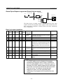
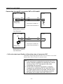
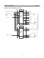
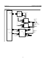
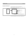
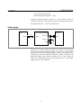
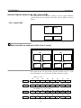
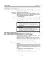
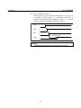
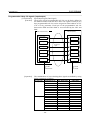
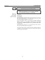
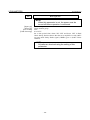
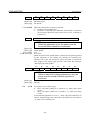
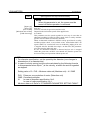
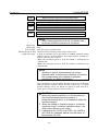
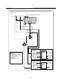
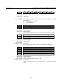
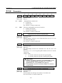
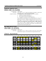
Interface Signals between the CNC and the PMC
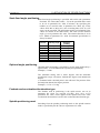
The addresses for the interface signals (F and G signal addresses
viewed from the CNC) between the CNC and the PMC are shown
below.
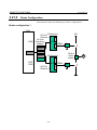
- [For 1-path CNC]
PMC
F0000~
G0000~
DCSPMC
F0000~
G0000~
T
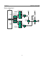
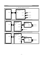
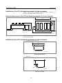
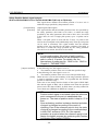
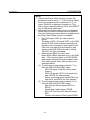
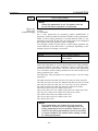
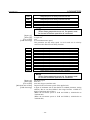
- [When two paths are used with a CNC of the T series]
CNC path 1
CNC path 2
PMC
F0000~
PMC
G0000~
F1000~
DCSPMC
F000~
G1000~
DCSPMC
G000~
F020~
G020~
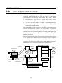
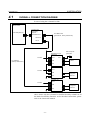
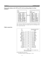
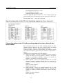
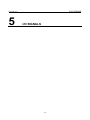
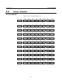
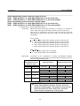
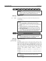
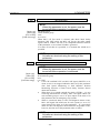
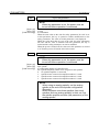
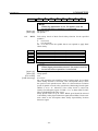
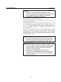
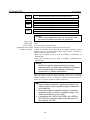
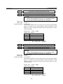
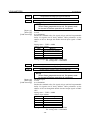
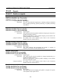
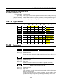
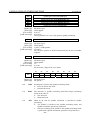
The signal for the x-th axis of the k-th path is placed in the (x - 1)-th
bit in the address (G or F) for the k-th path in the above figure.
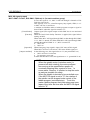
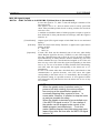
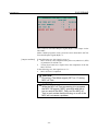
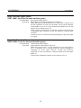
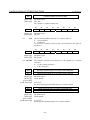
PMC ( n = k-1 )
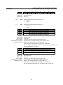
#7
#6
#5
Gn???
#4
#3
#2
#1
#0
5th axis 4th axis 3rd axis 2nd axis 1st axis
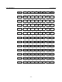
#7
#6
#5
Fn???
#4
#3
#2
#1
#0
5th axis 4th axis 3rd axis 2nd axis 1st axis
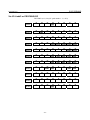
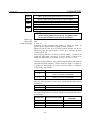
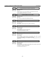
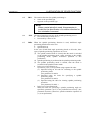
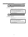
DCS PMC ( m = (k-1) × 20 )
#7
#6
#5
G0??+m
#4
#3
#2
#1
#0
5th axis 4th axis 3rd axis 2nd axis 1st axis
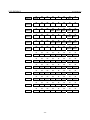
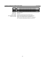
#7
#6
#5
F0??+m
#4
#3
#2
#1
#0
5th axis 4th axis 3rd axis 2nd axis 1st axis
- 86 -