1
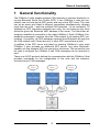
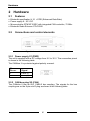
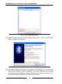
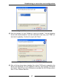
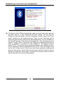
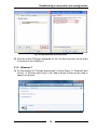
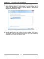
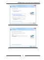
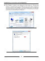
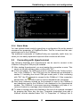
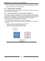
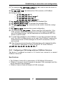
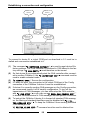
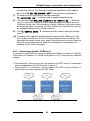
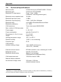
Manual CANblue II Intelligent Bluetooth/CAN Interface IXXAT Automation GmbH Leibnizstr. 15 88250 Weingarten Germany Tel.: +49 751 56146-0 Fax: +49 751 56146-29 Internet: www.ixxat.com E-Mail: [email protected] Support In case of unsolvable problems with this product or other IXXAT products please contact IXXAT in written form by: Fax: +49 751 56146-29 E-Mail: [email protected] Further international support contacts can be found on our webpage www.ixxat.com Copyright Duplication (copying, printing, microfilm or other forms) and the electronic distribution of this document is only allowed with explicit permission of IXXAT Automation GmbH. IXXAT Automation GmbH reserves the right to change technical data without prior announcement. The general business conditions and the regulations of the license agreement do apply. All rights are reserved. Registered trademarks All trademarks mentioned in this document and where applicable third party registered are absolutely subject to the conditions of each valid label right and the rights of particular registered proprietor. The absence of identification of a trademark does not automatically mean that it is not protected by trademark law. Document number: 4.01.0126.20000 Version: 1.2 Content 1 General functionality ......................................................................5 2 Hardware .........................................................................................6 2.1 Features .................................................................................. 6 2.2 Connections and control elements ....................................... 6 2.2.1 2.2.2 2.2.3 2.2.4 2.2.5 Power supply X1 (PWR) .......................................................... 6 CAN bus plug X2 (CAN)........................................................... 6 LED display .............................................................................. 7 Pushbutton ............................................................................... 8 Bluetooth .................................................................................. 8 3 Extended ASCII protocol ...............................................................9 4 Behavior of the CANblue II .......................................................... 10 4.1 Restore factory settings ...................................................... 10 4.2 Firmware Update .................................................................. 10 4.3 VCI Support .......................................................................... 10 4.4 Bluetooth transmission behavior......................................... 11 4.5 Switching the message format ............................................. 11 4.6 Autostart and handshake ..................................................... 11 4.7 Automatic stop of the CAN controller ................................ 12 4.8 CAN filter .............................................................................. 12 4.9 Loss of connection .............................................................. 13 4.10 Loss of messages ................................................................ 13 4.10.1 4.10.2 4.10.3 4.10.4 CAN receive buffer overflow ................................................. 13 Bluetooth transmission buffer overflow................................. 13 CAN transmission buffer overflow ........................................ 13 Loss of responses to commands .......................................... 13 4.11 CAN-Controller Errors ......................................................... 14 4.11.1 WARNING: ........................................................................... 14 4.11.2 BUS-OFF-Recovery: ............................................................ 14 5 Establishing a connection and configuration ............................ 15 5.1 Installing the virtual COM port ............................................ 15 5.1.1 Windows XP ........................................................................... 15 5.1.2 Windows 7 .............................................................................. 19 5.2 CanBlueCon Configuration Tool ......................................... 23 5.2.1 Command Line Parameters ................................................... 23 Copyright IXXAT Automation GmbH 3 CANblue II - Manual, Version 1.2 Content 5.2.2 Additional Commands ............................................................ 23 5.2.3 Interactive Mode .................................................................... 24 5.2.4 Batch Mode ............................................................................ 25 5.3 Connecting with Hyperterminal........................................... 25 5.4 Configuration examples....................................................... 26 5.4.1 Connecting CAN to the PC through the CANblue II .............. 26 5.4.2 Configuring a CAN bridge with two CANblue II devices ........ 27 5.4.3 Connecting another CANblue II ............................................. 29 6 Extended ASCII-Protocol Commands ........................................ 30 7 Appendix ...................................................................................... 30 7.1 Support ................................................................................. 30 7.2 Returning hardware.............................................................. 30 7.3 Disposing of old equipment ................................................ 30 7.4 Information on EMC ............................................................. 30 7.5 Compliance with RoHS directive ......................................... 31 7.6 FCC Compliance................................................................... 31 7.7 Japan Radio Equipment Compliance (TELEC) ................... 31 7.8 EC Declaration of Conformity.............................................. 33 7.9 Technical Specifications ...................................................... 34 Copyright IXXAT Automation GmbH 4 CANblue II - Manual, Version 1.2 General functionality 1 General functionality The CANblue II units enables multiple CAN networks to connect wirelessly using the Bluetooth Serial Port Profile (SPP). If two CANblue II units are connected, one unit acts as the SPP server and one as the SPP client. The units can act as server and client in different connections simultaneously, allowing more than two units – and thus multiple CAN networks – to be connected. To establish an SPP connection between two units, the unit acting as the client should be given the Bluetooth MAC address of the server. The client then attempts to establish a connection to the other CANblue II. Each CANblue II forwards the messages it receives from the CAN network to all existing SPP connections. Conversely, all CAN messages received from Bluetooth are sent into the CAN network and, if there are any, to other SPP connections as well. In addition to the SPP server and client for chaining CANblue II units, each CANblue II also provides an additional SPP server. Any other Bluetoothcapable unit that supports SPP can connect to this server. This connection can be used to configure the CANblue II and CAN messages can be received or sent. There is an ASCII protocol defined for communication with the CANblue II that provides commands for the configuration of the units and the transmission/receiving of CAN messages. Fig.: 1-1 Networking example Copyright IXXAT Automation GmbH 5 CANblue II - Manual, Version 1.2 Hardware 2 Hardware 2.1 Features Bluetooth specification V 2.1 + EDR (Enhanced Data Rate) Power supply 9 - 30 V DC Microcontroller STM32F103RC with integrated CAN controller, 72 MHz Bluetooth Radio Ericsson STLC2500 2.2 Connections and control elements Fig.: 2-1 Connections and control elements 2.2.1 Power supply X1 (PWR) The unit is supplied with a DC voltage from 9 V to 30 V. The connection pinout is shown in the following table. The CANblue II is protected against polarity reversal. X1 Pin no. 1 2 Signal PWR (+) GND (-) 2.2.2 CAN bus plug X2 (CAN) The CANblue II has an ISO 11898-2 bus coupling. The signals for the bus coupling are on the 9-pin sub-D plug as shown in the following table. Copyright IXXAT Automation GmbH 6 CANblue II - Manual, Version 1.2 Hardware X2 Pin no. 1 2 3 4 5 6 7 8 9 Signal CAN-L GND CAN-H - 2.2.3 LED display The CANblue II has three LEDs for signaling different states: LED Mode Display steady red CAN flashing green flashing red Bluetooth steady red flashing blue (2 Hz) flashing blue (10 Hz) steady blue Copyright IXXAT Automation GmbH Description No Bluetooth MAC address is stored in the configuration of the CANblue II, and there is no connection to an SPP server on the unit. A CAN message has been sent or received and the CAN controller is not in the warning state. A CAN message has been sent or received and the CAN controller is in the warning state. The CAN controller is in the BUS-OFF state. An attempt is made to establish a Bluetooth SPP connection with another Bluetooth device or a connection is being established to this device. Bluetooth SPP is used to send or receive data. There is at least one Bluetooth SPP connection to another device. 7 CANblue II - Manual, Version 1.2 Hardware 2.2.4 Pushbutton Pushbutton Description T1 T2 Restore factory settings see Section 4.1 Not used 2.2.5 Bluetooth The internal Bluetooth interface needs a unique MAC address (MAC-ID) to communicate. The MAC-ID is on the back of the device and is also used for the unique identification of devices when searching for them with Bluetooth. See also chapter 5, "Establishing a connection and configuration". Copyright IXXAT Automation GmbH 8 CANblue II - Manual, Version 1.2 Extended ASCII protocol 3 Extended ASCII protocol To configure and transmit Bluetooth CAN messages, there is an ASCII protocol defined. There is also a binary format available for the transmission of Bluetooth CAN messages to permit a better data rate. CANblue II units always use the binary format for CAN messages transmitted between them. ASCII commands have the following structure: Message type Command Parameter 1 … Parameter n LF or CR-LF Individual fields are separated by blanks. Multiple sequential blanks are considered to be a single blank. There is no distinction between capital and lower-case letters. A message is terminated with the ASCII linefeed control code (LF or "\n") or with a carriage return and linefeed (CR LF or "\r\n"). ASCII messages sent by the CANblue II are terminated with the same ASCII control codes as ASCII messages sent by the user. If the user has not yet sent any ASCII messages, the CANblue II uses CR-LF as the terminator. There are six different message types defined. The message type is defined by the first byte. "D" "C" "M" "X" "I" "E" Device-specific commands CAN-specific commands CAN messages in ASCII format CAN messages in binary format Info messages Error messages Examples: ASCII command „C CAN_INIT 250\n“ „C CAN_START\r\n“ „C FILTER_ADD EXT 7FA1 RTR\r\n“ „D SETTINGS_DEFAULT\n“ Response from the CANblue II „I OK: CAN_INIT\n“ „I OK: CAN_START\r\n“ „I OK: FILTER_ADD\r\n“ „I OK: SETTINGS_DEFAULT\n“ A list of all ASCII commands can be found in chapter 6 "Extended ASCII-Protocol Commands" (p.30). Copyright IXXAT Automation GmbH 9 CANblue II - Manual, Version 1.2 Behavior of the CANblue II 4 Behavior of the CANblue II 4.1 Restore factory settings If there is a "Config" connection to the CANblue II, the device can be reset to the factory settings using the command "D SETTINGS_DEFAULT". Without a Bluetooth connection, the device can also be reset as follows: (1) (2) (3) (4) (5) 4.2 Turn off the CANblue II. Press and hold button T1 Turn on the CANblue II; the CAN LED lights in red-green When the CAN LED flashes in red-green, release button T1 If the MODE LED flashes several times, this indicates that the configuration has been reset to factory settings Firmware Update Starting with firmware version 2.00.00, an update of the CANblue II firmware is possible. The files needed for updating the CANblue are supplied on CD or can be found in the installation folder. The firmware can be updated as follows: (1) Restore the CANblue II to factory defaults (2) Set up a virtual COM-Port (Config connection). (see 5.1 Installing the virtual COM port on p. 15) (3) Open the command prompt and navigate to the folder “FW-Update” on CD or in the installation folder. (4) Call FW-Update <COM-PORT> e.g. “FW-Update 5” (5) At first the new Firmware version and the firmware version of the device are displayed, after that the firmware update is performed (6) At the end the CANblue II restarts itself. During the restart the CAN and Mode LEDs should flicker red/green (7) The firmware version can be checked with CANblueCon and the command „D VERSION“ 4.3 VCI Support The CANblue II can also be used as VCI interface starting with firmware version 2.00.05 and VCI Version 3.5.1.3753. Therefore no special firmware has to be flashed. The VCI mode works best when the CANblue II is restored to factory defaults before and the CANblue II is not running in bridge mode. With reduced receive and transmit performance the parallel usage is also possible. Existing CAN filters will be cleared during VCI interface usage and will be restored afterwards. Therefore the CANblue II must be registered with the VCI- Copyright IXXAT Automation GmbH 10 CANblue II - Manual, Version 1.2 Behavior of the CANblue II V3 Device Server. Please read the VCI-V3 installation manual shipped with the VCI-V3 for detailed installation instruction. 4.4 Bluetooth transmission behavior With the standard configuration, pending messages are collected for up to 4 ms by the CANblue II before sending them via Bluetooth. The collecting resp. minimum time between two consecutive Bluetooth TX packets can be adjusted. To do this, the command "D BUFF_TIMEOUT" can be used to specify a time after which pending messages will be transmitted even if they don't complete a full Bluetooth SPP packet. A timeout of 0 indicates that data should be send immediately. This increases the protocol overhead. The size of a packet depends on the other node in the connection. CANblue II units use data packets of up to 669 bytes between themselves. 4.5 Switching the message format The command "C SEND_CAN_FRAMES" can be used on a "Config" connection to switch between ASCII and binary format, or the receipt of CAN messages can be disabled entirely (see chapter 6 “Extended ASCII-Protocol Commands”). The format is also changed in the following situations: • After a connection is established to the "Config" server, the transmission of CAN messages is disabled. • If the command "C CAN_START" is issued, the transmission format is switched to ASCII. • If the "Config" connection is used to sent a CAN message to the CANblue II in the ASCII or binary format, the CANblue II switches to the same format. If the CANblue II is in autostart mode and a handshake is carried out on the "Config" connection (see 4.6 Autostart and handshake), the device switches to the binary format. 4.6 Autostart and handshake If the autostart mode of the CANblue II is enabled (see command “C AUTOSTART”) and a SPP connection is established, it attempts to carry out a handshake to start the CAN controller. If a handshake is carried out between two CANblue II devices, both devices must have autostart mode enabled. However, a handshake can also be carried out on the "Config" connection. The corresponding responses to the handshake messages must then be sent manually by the user. Copyright IXXAT Automation GmbH 11 CANblue II - Manual, Version 1.2 Behavior of the CANblue II A handshake works as follows: After an SPP connection is established, the SPP server transmits its version information (e.g. "I CANblue Generic - Bridge v2.00.03“). The SPP client must then also send its own version information. If the SPP server receives no response to its version information, it sends the version information again after five seconds. Once the version information has been exchanged successfully, the SPP server starts its CAN controller at the configured baud rate and sends "I CAN STARTED" to the SPP client. The client then starts its own CAN controller and sends "I CAN STARTED" back to the SPP server. This concludes the handshake procedure and both CANblue II units will now exchange CAN messages in binary format. 4.7 Automatic stop of the CAN controller If there is no more SPP connection to the CANblue II, the CAN controller automatically stops. 4.8 CAN filter Messages received by the CAN controller can be filtered. Messages are filtered based on the identifier, the frame format (extended, standard), and the frame type (data, remote). Filter entries can be stored in the CANblue II for filtration. An entry consists of the frame format, the ID, and the frame type. Once filtering is activated, messages received by the CAN controller are only forwarded on the SPP connections if the messages correspond to a filter entry. 4096 standard filters can be entered. This includes all possible identifiers for the standard frame format. For the extended filter, there are 300 bytes of storage available. An extended filter entry occupies 8, 16, 24, or 32 bits depending on the number of CAN ID digits. Thus between 75 and 300 extended messages can be filtered. CAN-ID range 0-7F 80-7FFF 8000-7FFFFF 800000-1FFFFFFF Memory consumption in bytes 1 2 3 4 Copyright IXXAT Automation GmbH 12 CANblue II - Manual, Version 1.2 Behavior of the CANblue II The following commands are available for configuration of filtering: „C „C „C „C „C 4.9 FILTER_ADD“ FILTER_REMOVE“ FILTER_CLEAR“ FILTER_ENABLE“ FILTER_DISABLE“ Loss of connection If a CANblue II has stored a Bluetooth MAC address, then for five seconds it will attempt to establish an SPP connection to that address. If the connection attempt fails, then a new attempt is always started after two seconds. The loss of an existing SPP connection is detected after three seconds. After connection loss is detected, the SPP client immediately attempts to establish a new connection as described above. 4.10 Loss of messages 4.10.1 CAN receive buffer overflow The CAN receive buffer can overview is a Bluetooth connection to the CANblue II is established during high traffic on the connected CAN network or another connection is attempted. If this is the case, additional incoming CAN messages are discarded. If there is a config connection to the CANblue II, this is indicated with an error message ("E 84 Rx SW queue OVERRUN"). 4.10.2 Bluetooth transmission buffer overflow The CANblue II has a separate transmission buffer for every SPP connection. If one of these buffers fills up due to an excess number of CAN messages, any additional incoming messages for this buffer are discarded. If this involves the config connect, then once there is space in the buffer again an error message is send ("E 84 Rx SW queue OVERRUN"). 4.10.3 CAN transmission buffer overflow Due to flow control on the Bluetooth SPP connection, the CAN transmission buffer can normally not overflow. However, to avoid blocking the receipt of data on the SPP connections, in case of error (CAN controller in warning or BUS OFF state) or if there are more than 512 messages in the buffer, the oldest buffer entries are overwritten. 4.10.4 Loss of responses to commands If there is high data traffic between the SPP connections on the CANblue II devices and a command is sent on the config connection, it can occur that parts of the CANblue II response are discarded. Only entire lines of the re- Copyright IXXAT Automation GmbH 13 CANblue II - Manual, Version 1.2 Behavior of the CANblue II sponse are discarded, that is, the response is always terminated with a linefeed or carriage return and linefeed. 4.11 CAN-Controller Errors 4.11.1 WARNING: If the CAN controller is in the warning state due to multiple incorrectly received or transmitted messages, this can only be corrected by resetting the CANblue II or by the receipt or transmission of multiple valid CAN messages. The stopping and restarting of the CAN controller does not reset the warning state (except for BUS-OFF). 4.11.2 BUS-OFF-Recovery: If the CAN controller goes into BUS-OFF, the BUS-OFF recovery is automatically started. Five seconds after detection of the BUS-OFF state, the CAN controller is stopped for one second, and then restarted. If the CAN controller then detects 128 successive 11-bit sequences on the bus (128 valid messages), all error flags are reset on the CAN controller and the CAN controller is then placed back into the normal operating condition. The BUS-OFF recovery is carried out until the CAN controller is in normal operating mode or is stopped through the config connection (see command “C CAN_STOP”). The BUS-OFF recovery can also be carried out manually by using the config connect to stop and restart the CAN controller. Copyright IXXAT Automation GmbH 14 CANblue II - Manual, Version 1.2 Establishing a connection and configuration 5 Establishing a connection and configuration Each CANblue II provides two virtual SPP servers as a service. The names of the SPP servers are "Config" and "SPP". To configure a CANblue II, a Bluetooth-capable device that supports the serial port profile (SPP) must be used to establish a connection to the Config server. To connect to the Config server of a CANblue II, a virtual COM port must be installed for the SPP connection on the device used. The user can see the virtual COM port as a physical COM connection present on the device which is connected through a cable to a CANblue II. The following values must be used for the properties of the COM port. Baudrate Data bits Parity Bit Stop bits Flow control 921600 8 none 1 hardware The COM port can be used with a terminal program, for example. To configure the CANblue II and CAN message exchange, the "Extended ASCII protocol" must be used (see section 3 on p.9 and section 6 Extended ASCII-Protocol Commands on p.30). 5.1 Installing the virtual COM port The following two sections describe step by step how a Bluetooth device is added under Windows XP and Windows7 and then used to establish a connection to a CANblue II on a virtual COM port 5.1.1 Windows XP (1) Open the dialog "Bluetooth devices" (Control Panel Bluetooth devices). Use the "Add" button to open the Bluetooth device addition wizard. Copyright IXXAT Automation GmbH 15 CANblue II - Manual, Version 1.2 Establishing a connection and configuration Fig.: 5-1 XP - Bluetooth devices (2) Check "My device is set up and ready to be found ", then use the "Next" button to search for devices. Fig.: 5-2 XP Bluetooth device wizard - Welcome (3) All available devices will then be displayed. The CANblue II devices have names like "CANblue II ([MAC address])". The MAC address can be found on the back of the CANblue II. Select the device to which you want to connect and confirm the selection with the "Next" button. Copyright IXXAT Automation GmbH 16 CANblue II - Manual, Version 1.2 Establishing a connection and configuration Fig.: 5-3 XP Bluetooth device wizard - Devices found (4) Now the passkey for the CANblue II must be entered. "Use the passkey found in the documentation" must be selected for the entry, and "7388" entered as the passkey. Confirm the input with "Next". Fig.: 5-4 XP Bluetooth device wizard - passkey (5) After all drivers have been installed, the virtual COM ports created for the device are displayed. For the CANblue II devices, two outgoing COM ports are shown. One of these two COM ports is provided for the Config connection of "non-CANblue devices". Copyright IXXAT Automation GmbH 17 CANblue II - Manual, Version 1.2 Establishing a connection and configuration Fig.: 5-5 XP Bluetooth device wizard - Completion (6) To find out which COM port should be used, you must query the names of the SPP servers. In the "Bluetooth Devices" dialog, you will see the CANblue II you just added. Use the "Properties" button to open the "Properties" window for the selected device. Click on the "Services" tab to search for the services of the device and display them. For the CANblue II, the two SPP servers of the device are shown here. One of these servers is named "Config". Next to the name, the COM port is displayed that can be used to establish a connection to the CANblue II. The second service, named "SPP", is reserved for a connection between two CANblue II devices. No connection can be established to this server. If the checkmark is not set for the Config service, there may have been problems installing the driver for this service. Check the box and confirm with the "Apply" button to attempt to install the driver again. An Internet connection may be necessary so that the driver can be downloaded. Copyright IXXAT Automation GmbH 18 CANblue II - Manual, Version 1.2 Establishing a connection and configuration Fig.: 5-6 XP Bluetooth device services (7) Now the virtual COM port displayed for the Config connection can be used to connect to the CANblue II. 5.1.2 Windows 7 (1) On the window for "Devices and printers" (Control Panel "Hardware and Sound" "Devices and Printer"), the "Add a device" button can be used to search for devices. Fig.: 5-7 W7 - Devices and printer Copyright IXXAT Automation GmbH 19 CANblue II - Manual, Version 1.2 Establishing a connection and configuration (2) Select the desired device and confirm with "Next". The CANblue II devices have names like "CANblue II ([MAC address])". The MAC address can be found on the back of the CANblue II. Once the addition is complete, the window can be closed with "Close". Fig.: 5-8 W7 - Adding a device (3) Now the pairing code for the CANblue II must be entered. "Enter the device’s pairing code" must be selected for the entry, and "7388" entered as the pairing code. Confirm the input with "Next". Copyright IXXAT Automation GmbH 20 CANblue II - Manual, Version 1.2 Establishing a connection and configuration Fig.: 5-9 W7 – Enter device pairing code Fig.: 5-10 W7 – pairing code Copyright IXXAT Automation GmbH 21 CANblue II - Manual, Version 1.2 Establishing a connection and configuration (4) The CANblue II added is now displayed on the window for "Devices and Printers". To determine the virtual COM port that can be used to connect to the Config server of the CANblue II, on the Services tab on the properties window for the device (right click on the device Properties) you can query the services provided by the CANblue II. Fig.: 5-11 W7 - Devices and printer - Device Properties Fig.: 5-12 W7 - Bluetooth device services Copyright IXXAT Automation GmbH 22 CANblue II - Manual, Version 1.2 Establishing a connection and configuration (5) Here is where the two SPP servers and the corresponding COM ports are displayed. The COM port required to connect the PC to the CANblue II is next to the SPP services with the name "Config". If the checkmark is not set for the Config service, there may have been problems installing the driver for this service. Check the box and confirm with the "Apply" button to attempt to install the driver again. An Internet connection may be necessary so that the driver can be downloaded. 5.2 CanBlueCon Configuration Tool To set up the CANblue II, the CanBlueCon tool is provided. It is capable of reading a configuration file with given commands and supports a command history, so that you can scroll through your last issued commands by pressing the UP/DOWN keys. 5.2.1 Command Line Parameters CanBlueCon.exe COM_PORT_NUMBER (Console input) CanBlueCon.exe COM_PORT_NUMBER FILENAME (Input from file) Example CanBlueCon.exe 4 Config.txt The first parameter is mandatory. If you omit the second parameter “FILENAME”, CanBlueConfig will automatically start up in interactive mode. If you specify a file in the second parameter, CanBlueConfig will start in batch mode. In interactive mode, CanBlueConfig expects command input from the console, in batch mode it will read the commands from the specified text file. 5.2.2 Additional Commands Additionally to the CANblue commands described in chapter 6 “Extended ASCII-Protocol Commands”, the CanBlueCon supports the following “local” commands which start with a “#” character. These commands are interpreted locally and allow the user to implement a cyclic transmission, for instance. Copyright IXXAT Automation GmbH 23 CANblue II - Manual, Version 1.2 Establishing a connection and configuration The following additional commands are available: Command #delay #goto Parameter <DELAY_TIME> <LABEL_NAME> #help #label #pause #print #exit <LABEL_NAME> <TEXT> - Description delay in execution for specified time (in sec) continue execution from string where label is defined print a help screen define label wait until any key pressed print text on display abort the program An example of a CANblue II command with local echo and CANblue II reply: >c can_init 1000 I OK: CAN_INIT An example of a local command with local output: >#print CANblue Generic # CANblue Generic 5.2.3 Interactive Mode The basic usage of CanBlueConfig in Interactive mode is equal to HyperTerminal. Just type in the command you want to execute and press return. However, CanBlueConfig provides some additional commands to control the execution of the standard commands. For a reference to these commands see section 5.2.2 Additional Commands. Copyright IXXAT Automation GmbH 24 CANblue II - Manual, Version 1.2 Establishing a connection and configuration Figure 5.2-1: CANblueCon 5.2.4 Batch Mode You can activate batch mode by specifying a configuration file as the second command line parameter of CanBlueCon.exe. The file is read and the commands are sent to the CANblue II. The additional commands of CanBlueConfig are especially useful here, because you can easily implement loops and other constructs with them. 5.3 Connecting with Hyperterminal The following describes how Hyperterminal can be used to connect to the CANblue II using the COM port just installed. (1) After starting Hyperterminal, you must assign the connection a name. This name can be any arbitrary name; confirm with "OK".. (2) In the next dialog, the COM port must be selected for the Config connection to the CANblue II. The COM port can be determined as described in section 5.1 Installing the virtual COM port under point 6. After confirming with "OK", the PC attempts to connect to the CANblue II. If the connection attempt fails, the button can be used to reestablish the connection. (3) Now every character entered on the keyboard is sent to the CANblue II and characters sent by the CANblue II are displayed in the Hyperterminal window. The CANblue II processes incoming messages only when it receives a linefeed or a carriage return followed by a linefeed. (4) To send a carriage return and linefeed at the end of an entered command by pressing the Enter key, the box "Terminate transmitted lines with a linefeed" must be checked under "File" "Properties" "Settings" tab Copyright IXXAT Automation GmbH 25 CANblue II - Manual, Version 1.2 Establishing a connection and configuration "ASCII configuration". For better clarity, the "Output characters entered locally (local echo)" can be checked as well. 5.4 Configuration examples The following three examples describe how CANblue II devices can be configured for different requirements. 5.4.1 Connecting CAN to the PC through the CANblue II The following example describes how a previously installed virtual COM port can be used to configure the CANblue II to exchange data with a CAN network connected to the CANblue II. Communication through the COM port can, for example, be carried out with Hyperterminal as described in chapter 5.3. The following specifications apply in the example: The CAN network is operated at a data rate of 500 kBaud. Only the following CAN message should be forwarded by the CANblue II device A: o Data and remote frames with standard identifier 5 o Remote frames with standard identifier 1F. o Data frames with extended identifier 1A2B3C Fig.: 5-13 CANblue II – PC connection Copyright IXXAT Automation GmbH 26 CANblue II - Manual, Version 1.2 Establishing a connection and configuration (1) The command "D SETTINGS_DEFAULT " is used to reset the device to factory settings. (2) "C CAN_INIT 500 " initializes the CAN controller to 500 kBaud. (3) Setting the filter: o „C FILTER_ADD 5 “ o „C FILTER_ADD STD 5 RTR “ o „C FILTER_ADD STD 1F “ o „C FILTER_ADD EXT 1A2B3C “ (4) "C FILTER_ENABLE STD " activates the standard filter. (5) "C FILTER_ENABLE EXT " activates the extended filter. (6) The "C CONFIG SHOW " command can be used to check the configuration. (7) "C CONFIG SAVE " saves the current configuration. (8) The command "C CAN_START " then starts the CAN controller. If the CAN controller receives a message from the CAN network that matches one of the filters entered, it will be transmitted on the Bluetooth SPP connection in ASCII format. (9) To send CAN messages to the CANblue II or into the connected CAN network, the ASCII or binary format can be used. The CANblue II matches the transmission format of CAN messages on the SPP connection to the format received. (10) The following command sends a CAN data frame with standard identifier 7FF and the 7 data bytes "1A 2B 3C 4D 5E 6F 70" to the CAN bus: „M SD7 7FF 1A 2B 3C 4D 5E 6F 70 “ 5.4.2 Configuring a CAN bridge with two CANblue II devices The device A configured as shown in 4.5 should now connect to a second CANblue II device B. Specifications: The CANblue II device B is connected to a 1000 kBaud CAN network. CANblue II device A should forward all standard CAN messages and filter out all extended CAN messages. CANblue II device B should forward all CAN messages. Copyright IXXAT Automation GmbH 27 CANblue II - Manual, Version 1.2 Establishing a connection and configuration Fig.: 5-14 CANblue II - Bridge To connect to device B, a virtual COM port as described in 5.1 must be installed and a connection established to it. (1) The command "D SETTINGS_DEFAULT " is used to reset device B to factory settings. The CAN controller is initialized to 1000 kBaud in the factory settings. "C CAN_INIT " need therefore not be issued. (2) So that device B can automatically start the CAN controller after connected to another CANblue II, the "C AUTOSTART ON " command must be used to enable autostart mode. (3) "C CONFIG SAVE " saves the configuration. (4) If it does not exist, the connection to the virtual COM port of the Config connection of the CANblue II device A must be reestablished. (5) If device A is currently sending CAN messages on the Config connection, we recommend turning it off to simplify configuration. To turn off the transmission of CAN messages, you can either stop the CAN controller with "C CAN_STOP " or you can use "C SEND_CAN_FRAMES OFF " to disable the transmission of CAN messages on that specific connection. (6) To instruct the CANblue II device A to forward all standard CAN messages, the filtering of standard identifiers must be disabled with "C FILTER_DISALBE STD ". To keep the CANblue II from sending extended CAN messages, the "C FILTER_CLEAR EXT " command must be used to delete all exCopyright IXXAT Automation GmbH 28 CANblue II - Manual, Version 1.2 Establishing a connection and configuration (7) (8) (9) (10) tended filter entries. The filtering of extended identifiers is still enabled due to the "C FILTER_ENABLE EXT" in the previous configuration. To allow the CAN controller to start automatically, "C AUTOSTART ON " must be used to enable autostart mode. The command "D MAC_ADD [address of device B] " tells device A to connect to device B. Since autostart mode is enabled on both CANblue II units, the CAN controllers of both CANblue II units are started automatically after connecting. The two CANblue II units will now function as a bridge between the two CAN networks. The "C CONFIG SAVE " command can be used to save the configuration. To achieve the highest possible data rate between the CANblue II units, the Config connection to the PC should be disconnected. Since the configuration is stored on both units, even if the devices are turned off and on they will reconnected without additional configuration and resume forwarding of their CAN messages. 5.4.3 Connecting another CANblue II To connect a third CAN bus using an additional CANblue II device C with the CAN buses of CANblue II A and B configured in 5.4.2, there are two different options: From device B, which has so far only acted as an SPP server, a connection can be established to the SPP server of device C. From device C, a connection can be made to the SPP server of device A, which has so far only acted as an SPP client. Fig.: 5-15 CANblue II - Bridge chain Copyright IXXAT Automation GmbH 29 CANblue II - Manual, Version 1.2 Extended ASCII-Protocol Commands It should be noted that each additional CANblue II increases the rate of CAN messages on the Bluetooth-SPP connections and simultaneously reduces the maximum possible data rate of all SPP connections with each additional SPP connection added. 6 Extended ASCII-Protocol Commands A detailed description of the ASCII commands can befound on the CD as a PDF document: „4.01.0126.20000_CANblue-II_Manual_V1.1.pdf“ or on your computer in Program Files/Ixxat/CANblue II Generic/Docu. 7 Appendix 7.1 Support For more information on our products, FAQ lists and installation tips, please refer to the support area on our homepage (http://www.ixxat.de). There you will also find information on current product versions and available updates. 7.2 Returning hardware If it is necessary to return hardware to us, please download the relevant RMA form from our homepage and follow the instructions on this form. 7.3 Disposing of old equipment This product is covered by ElektoG (WEEE) and has to be disposed according to ElektoG (WEEE) separately. Products of IXXAT, which are covered by ElektoG, are exclusively for commercial use and marked with the symbol of the crossed-out garbage can. According to the B2B regulations, the disposal in accordance with § 10 para. 2 clause 3 Electrical and Electronic Equipment act in the version of 16.03.2005 is regulated separately in the General Terms and Conditions and its supplements of IXXAT. The terms and conditions, its supplements and other information on disposal of old equipment can be downloaded at www.ixxat.de. 7.4 Information on EMC The product is a class B device. If the product is used in office or home environment radio interference can occur under certain conditions. To ensure faultless operation of the device, the following instructions must be followed due to technical requirements of EMC: use only the included accessories the shield of the interfaces must be connected with the device plug and with the plug on the other side Copyright IXXAT Automation GmbH 30 CANblue II - Manual, Version 1.2 Appendix 7.5 Compliance with RoHS directive CANBlue II was produced according to the RoHS (Restriction of the use of certain Hazardous substances in electrical and electronic equipment) directive and complies with the directive. 7.6 FCC Compliance Declaration of conformity This device complies with Part 15 of the FCC Rules. Operation is subject to the following two conditions: This device may not cause harmful interference, and this device must accept any interference received, including interference that may cause undesired operation FCC Identifier of the built in Bluetooth module: PVH0939 Test remit: FCC Rules 47 CFR Part 15 / 2010-01-09 Subpart B - Class B / Section 15.107 and 15.109 in accordance with the procedures given in ANSI C63.4-2003 – 01/2004 7.7 Japan Radio Equipment Compliance (TELEC) CANBlue II uses the cB-0939 module which complies with the Japanese Technical Regulation Conformity Certification of Specified Radio Equipment (ordinance of MPT N°. 37, 1981), Article 2, Paragraph 1, Item 19, "2.4GHz band wide band low power data communication system". The cB-0939 MIC certification number is 204WW11100200. Copyright IXXAT Automation GmbH 31 CANblue II - Manual, Version 1.2 Appendix Copyright IXXAT Automation GmbH 32 CANblue II - Manual, Version 1.2 Appendix 7.8 EC Declaration of Conformity IXXAT Automation hereby declares that the product: with the article numbers: 1.01.0126.11000 1.01.0126.11001 1.01.0126.12000 1.01.0126.12001 do comply with the EC directives 2004/108/EC und 1999/5/EC Art. 3b. Applied harmonized standards in particular: ETSI EN 301489-1 / V1.8.1 (2008-04) EN 61000-6-2:2005 11.10.2011, Dipl.-Ing. Christian Schlegel , Managing Director IXXAT Automation GmbH Leibnizstr. 15 88250 Weingarten Copyright IXXAT Automation GmbH 33 CANblue II - Manual, Version 1.2 Appendix 7.9 Technical Specifications Microcontroller: ST-Microelectronics STM32F103RC / 72 MHz Bluetooth radio: ST-Ericsson STLC2500DB Bluetooth RF output power: Class 1, max 14 dBm (conducted - excluding antenna gain) Bluetooth receive sensitive level: -91 dBm Bluetooth input level (max): +5 dBm Bluetooth output frequency: 2.402 - 2.480 GHz, ISM band Bluetooth stack: connectBlue Embedded Bluetooth Stack Bluetooth qualification: 2.1 + EDR CAN transceiver: Texas Instruments SN65HVD251 Max. number of CAN bus nodes: 120 Power supply: 9 - 30 V DC Power consumption: typically 50 mA at 12 V Dimensions (L x W x H) in mm: 81 x 66 x 26 Weight: approx. 83 g Working temperature range: -40° C to +85° C Relative humidity: 10-95 %, non-condensing Protection type: IP 20 CAN interface isolation working voltage: 130 V AC/DC (Continuous) 1000 V DC (1 Second) External antenna version: RP-SMA connector, max. antenna gain 3.4 dBi Bridge set-up time: typically 3-4 seconds Bluetooth transfer delay: approx. 4 ms (average) (CAN-Bluetooth or Bluetooth-CAN) CAN transmission rate: * 100% Bus load at 1 MBit Maximal distance between two devices in bridge mode: * 300 meter / 1000 feet (internal antenna version) Depending on configured Bluetooth connection profile („D LINK_POLICY SHORTEST_LATENCY“), connection quality and distance between sender and receiver. Copyright IXXAT Automation GmbH 34 CANblue II - Manual, Version 1.2


![[1]StorageTek Linear Tape File System, Open Edition](http://vs1.manualzilla.com/store/data/005641506_1-83def2383162ce3771fdbc891794971f-150x150.png)