1
TCA8000 and TCA8500 Timing Server
Installation and Configuration Guide
Modified: 2015-08-31
Copyright © 2015, Juniper Networks, Inc.
Juniper Networks, Inc.
1133 Innovation Way
Sunnyvale, California 94089
USA
408-745-2000
www.juniper.net
Juniper Networks, Junos, Steel-Belted Radius, NetScreen, and ScreenOS are registered trademarks of Juniper Networks, Inc. in the United
States and other countries. The Juniper Networks Logo, the Junos logo, and JunosE are trademarks of Juniper Networks, Inc. All other
trademarks, service marks, registered trademarks, or registered service marks are the property of their respective owners.
Juniper Networks assumes no responsibility for any inaccuracies in this document. Juniper Networks reserves the right to change, modify,
transfer, or otherwise revise this publication without notice.
TCA8000 and TCA8500 Timing Server Installation and Configuration Guide
Copyright © 2015, Juniper Networks, Inc.
All rights reserved.
Revision History
August 2015—Release 3.6.0.
The information in this document is current as of the date on the title page.
YEAR 2000 NOTICE
Juniper Networks hardware and software products are Year 2000 compliant. Junos OS has no known time-related limitations through the
year 2038. However, the NTP application is known to have some difficulty in the year 2036.
END USER LICENSE AGREEMENT
The Juniper Networks product that is the subject of this technical documentation consists of (or is intended for use with) Juniper Networks
software. Use of such software is subject to the terms and conditions of the End User License Agreement (“EULA”) posted at
http://www.juniper.net/support/eula.html. By downloading, installing or using such software, you agree to the terms and conditions of
that EULA.
ii
Copyright © 2015, Juniper Networks, Inc.
Table of Contents
About the TCA8000 and TCA8500 Timing Server . . . . . . . . . . . . . . . . . . . . xiii
Documentation Conventions . . . . . . . . . . . . . . . . . . . . . . . . . . . . . . . . . . . . . . xiii
Requesting Technical Support . . . . . . . . . . . . . . . . . . . . . . . . . . . . . . . . . . . . . xiii
Self-Help Online Tools and Resources . . . . . . . . . . . . . . . . . . . . . . . . . . . xiv
Opening a Case with JTAC . . . . . . . . . . . . . . . . . . . . . . . . . . . . . . . . . . . . . xiv
Part 1
TCA8000 and TCA8500 Timing Server Overview
Chapter 1
TCA8000 and TCA8500 Timing Server Description . . . . . . . . . . . . . . . . . . . . 3
TCA8000 and TCA8500 Timing Server Description . . . . . . . . . . . . . . . . . . . . . . . . 3
TCA8000 and TCA8500 Chassis Overview . . . . . . . . . . . . . . . . . . . . . . . . . . . . . . . 3
Part 2
Installing and Setting Up a TCA8000 or TCA8500 Timing Server
Chapter 2
Installing and Setting Up a TCA8000 or TCA8500 Timing Server . . . . . . . . 11
Unpacking the TCA8000 or TCA8500 Timing Server . . . . . . . . . . . . . . . . . . . . . . . 11
Requirements for Installing a TCA8000 or TCA8500 Timing Server . . . . . . . . . . . 11
Reserving an IP Address for the TCA8000 or TCA8500 Timing Server . . . . . . . . . 12
Installing the TCA8000 or TCA8500 Timing Server . . . . . . . . . . . . . . . . . . . . . . . . 12
Recommendations for Mounting the Antenna (TCA8000 or TCA8500 Timing
Server) . . . . . . . . . . . . . . . . . . . . . . . . . . . . . . . . . . . . . . . . . . . . . . . . . . . . . . . . 12
Optimal GPS Antenna Mounting Conditions . . . . . . . . . . . . . . . . . . . . . . . . . . 13
Minimal TCA8000 or TCA8500 Timing Server Installation Conditions . . . . . 13
Mounting the Antenna . . . . . . . . . . . . . . . . . . . . . . . . . . . . . . . . . . . . . . . . . . . . 13
Changing the Password of Admin User Account . . . . . . . . . . . . . . . . . . . . . . . . . . . 14
Assigning an IP Address to the TCA8000 or TCA8500 Timing Server . . . . . . . . . 16
Visually Testing the TCA8000 or TCA8500 Timing Server With GPS . . . . . . . . . . 17
Verifying the Product T1/E1 Interface Support . . . . . . . . . . . . . . . . . . . . . . . . . . . . . 18
Part 3
Configuring and Upgrading the TCA8000 or TCA8500 Timing
Server
Chapter 3
Configuring a TCA8000 or TCA8500 Timing Server . . . . . . . . . . . . . . . . . . . 21
TCA User Accounts Overview . . . . . . . . . . . . . . . . . . . . . . . . . . . . . . . . . . . . . . . . . . 21
Guidelines for User Account Management . . . . . . . . . . . . . . . . . . . . . . . . . . . 22
Dynamic SSL Certificate Overview . . . . . . . . . . . . . . . . . . . . . . . . . . . . . . . . . . . . . 23
Accessing the User Interface . . . . . . . . . . . . . . . . . . . . . . . . . . . . . . . . . . . . . . . . . . 23
Requirements for Using the Graphical User Interface . . . . . . . . . . . . . . . . . . . . . . 24
Accessing the Graphical User Interface . . . . . . . . . . . . . . . . . . . . . . . . . . . . . . . . . . 24
Changing/Resetting the Login Password for Admin User . . . . . . . . . . . . . . . . . . . . 25
Changing the IP Address . . . . . . . . . . . . . . . . . . . . . . . . . . . . . . . . . . . . . . . . . . . . . 27
Copyright © 2015, Juniper Networks, Inc.
iii
TCA8000 and TCA8500 Timing Server Installation and Configuration Guide
Setting Precision Time Protocol (PTP) Parameters . . . . . . . . . . . . . . . . . . . . . . . . 30
Setting NTP Parameters . . . . . . . . . . . . . . . . . . . . . . . . . . . . . . . . . . . . . . . . . . . . . 32
Enabling the NTP Support . . . . . . . . . . . . . . . . . . . . . . . . . . . . . . . . . . . . . . . . 32
Creating an NTP Association Entry . . . . . . . . . . . . . . . . . . . . . . . . . . . . . . . . . 34
Modifying an Existing NTP Association Entry . . . . . . . . . . . . . . . . . . . . . . . . . 35
Deleting an Existing NTP Association Entry . . . . . . . . . . . . . . . . . . . . . . . . . . . 35
Configuring the MD5 Key List . . . . . . . . . . . . . . . . . . . . . . . . . . . . . . . . . . . . . . 35
Configuring Alarms . . . . . . . . . . . . . . . . . . . . . . . . . . . . . . . . . . . . . . . . . . . . . . . . . 36
Configuring Traps . . . . . . . . . . . . . . . . . . . . . . . . . . . . . . . . . . . . . . . . . . . . . . . . . . . 40
Specifying SNMPv3 Contacts . . . . . . . . . . . . . . . . . . . . . . . . . . . . . . . . . . . . . 40
Creating Trap Targets . . . . . . . . . . . . . . . . . . . . . . . . . . . . . . . . . . . . . . . . . . . . . 41
Deleting Trap Targets . . . . . . . . . . . . . . . . . . . . . . . . . . . . . . . . . . . . . . . . . . . . . 41
Creating SNMPv3 Users . . . . . . . . . . . . . . . . . . . . . . . . . . . . . . . . . . . . . . . . . . 41
Managing TCA User Accounts . . . . . . . . . . . . . . . . . . . . . . . . . . . . . . . . . . . . . . . . . 42
Creating an User Account . . . . . . . . . . . . . . . . . . . . . . . . . . . . . . . . . . . . . . . . . 42
Modifying an Existing User Account . . . . . . . . . . . . . . . . . . . . . . . . . . . . . . . . . 43
Deleting an Existing User Account . . . . . . . . . . . . . . . . . . . . . . . . . . . . . . . . . . 44
Changing the Login Password for Read/Write User . . . . . . . . . . . . . . . . . . . . . . . . 44
Configuring User Authentication through RADIUS . . . . . . . . . . . . . . . . . . . . . . . . . 45
Adding a New RADIUS Authentication Server Entry . . . . . . . . . . . . . . . . . . . . 48
Deleting a RADIUS Authentication Server Entry . . . . . . . . . . . . . . . . . . . . . . . 48
Modifying RADIUS Authentication Server Entry Details . . . . . . . . . . . . . . . . . 48
Configuring Authentication Order . . . . . . . . . . . . . . . . . . . . . . . . . . . . . . . . . . 49
Configuring RADIUS Accounting . . . . . . . . . . . . . . . . . . . . . . . . . . . . . . . . . . . . . . . 49
Adding a New RADIUS Accounting Server Entry . . . . . . . . . . . . . . . . . . . . . . . 52
Deleting a RADIUS Accounting Server Entry . . . . . . . . . . . . . . . . . . . . . . . . . . 52
Modifying RADIUS Accounting Server Entry Details . . . . . . . . . . . . . . . . . . . . 53
Specifying Recipients for Alarm E-Mail Notifications . . . . . . . . . . . . . . . . . . . . . . . 53
Adding a User to the E-Mail List . . . . . . . . . . . . . . . . . . . . . . . . . . . . . . . . . . . . 53
Removing a User from the Alarm Event Recipient List . . . . . . . . . . . . . . . . . . 56
Resetting Factory Defaults . . . . . . . . . . . . . . . . . . . . . . . . . . . . . . . . . . . . . . . . . . . 56
Stopping and Restarting the TCA8000 or TCA8500 Timing Server . . . . . . . . . . . 57
Chapter 4
Upgrading the TCA8000 and TCA8500 Software . . . . . . . . . . . . . . . . . . . . 59
Upgrade Requirements . . . . . . . . . . . . . . . . . . . . . . . . . . . . . . . . . . . . . . . . . . . . . . 59
Selecting Between the Pre-Installed Software Images Using a GUI/Browser . . . 60
Upgrading the Software Using a GUI/Browser . . . . . . . . . . . . . . . . . . . . . . . . . . . . 60
Selecting Between the Pre-Installed Software Images Using the CLI . . . . . . . . . . 62
Upgrading the Software Using the CLI . . . . . . . . . . . . . . . . . . . . . . . . . . . . . . . . . . 63
Selecting Between the Pre-Installed Software Images Using the Hardware
Mechanism . . . . . . . . . . . . . . . . . . . . . . . . . . . . . . . . . . . . . . . . . . . . . . . . . . . . 64
Part 4
Understanding the TCA8000 and TCA8500 Graphical User
Interface (GUI)
Chapter 5
Understanding the TCA8000 and TCA8500 Login Page . . . . . . . . . . . . . . . 69
Login Page Description . . . . . . . . . . . . . . . . . . . . . . . . . . . . . . . . . . . . . . . . . . . . . . 69
Accessing the Login Page . . . . . . . . . . . . . . . . . . . . . . . . . . . . . . . . . . . . . . . . . . . . 69
Understanding the Login Page . . . . . . . . . . . . . . . . . . . . . . . . . . . . . . . . . . . . . . . . 70
iv
Copyright © 2015, Juniper Networks, Inc.
Table of Contents
Chapter 6
Understanding the TCA8000 and TCA8500 System Status Page . . . . . . . 73
Understanding System LEDs . . . . . . . . . . . . . . . . . . . . . . . . . . . . . . . . . . . . . . . . . . 73
Port LEDs . . . . . . . . . . . . . . . . . . . . . . . . . . . . . . . . . . . . . . . . . . . . . . . . . . . . . . 73
IEEE 1588-2008 Sync LED . . . . . . . . . . . . . . . . . . . . . . . . . . . . . . . . . . . . . . . . 73
Status Page Description . . . . . . . . . . . . . . . . . . . . . . . . . . . . . . . . . . . . . . . . . . . . . . 74
Accessing the Status Page . . . . . . . . . . . . . . . . . . . . . . . . . . . . . . . . . . . . . . . . . . . . 74
Understanding the Status Page . . . . . . . . . . . . . . . . . . . . . . . . . . . . . . . . . . . . . . . . 75
The Status Page–System Pane . . . . . . . . . . . . . . . . . . . . . . . . . . . . . . . . . . . . 75
The Status Page—Alarm Pane . . . . . . . . . . . . . . . . . . . . . . . . . . . . . . . . . . . . . 77
The Status Page—E1 Pane . . . . . . . . . . . . . . . . . . . . . . . . . . . . . . . . . . . . . . . . 78
The Status Page—Timing Pane . . . . . . . . . . . . . . . . . . . . . . . . . . . . . . . . . . . . 80
The Status Page—PTP Pane . . . . . . . . . . . . . . . . . . . . . . . . . . . . . . . . . . . . . . 82
The Status Page—NTP Pane . . . . . . . . . . . . . . . . . . . . . . . . . . . . . . . . . . . . . . 85
The Status Page—GPS Pane (When GPS Option Is Connected) . . . . . . . . . . 87
Chapter 7
Understanding the TCA8000 and TCA8500 Config Page . . . . . . . . . . . . . . 89
Config Page Description . . . . . . . . . . . . . . . . . . . . . . . . . . . . . . . . . . . . . . . . . . . . . 89
Accessing the Config Page . . . . . . . . . . . . . . . . . . . . . . . . . . . . . . . . . . . . . . . . . . . 89
Understanding the Config Page . . . . . . . . . . . . . . . . . . . . . . . . . . . . . . . . . . . . . . . . 91
The Config Page—Network Pane . . . . . . . . . . . . . . . . . . . . . . . . . . . . . . . . . . . 92
The Config Page—Timing Pane . . . . . . . . . . . . . . . . . . . . . . . . . . . . . . . . . . . . 95
The Config Page—E1 Pane . . . . . . . . . . . . . . . . . . . . . . . . . . . . . . . . . . . . . . . . 98
The Config Page—PTP Pane . . . . . . . . . . . . . . . . . . . . . . . . . . . . . . . . . . . . . . 101
TCA8000 and TCA8500 Timing Server Configurable Profiles . . . . . . . 105
The Config Page—NTP Pane . . . . . . . . . . . . . . . . . . . . . . . . . . . . . . . . . . . . . . 107
The Config Page—MD5 Pane . . . . . . . . . . . . . . . . . . . . . . . . . . . . . . . . . . . . . 109
The Config Page—Trap Pane . . . . . . . . . . . . . . . . . . . . . . . . . . . . . . . . . . . . . . 110
The Config Page—SNMPv3 Pane . . . . . . . . . . . . . . . . . . . . . . . . . . . . . . . . . . . 111
The Config Page—Users Pane . . . . . . . . . . . . . . . . . . . . . . . . . . . . . . . . . . . . . 113
The Config Page—Profile Pane . . . . . . . . . . . . . . . . . . . . . . . . . . . . . . . . . . . . 114
The Config Page—RADIUS Pane . . . . . . . . . . . . . . . . . . . . . . . . . . . . . . . . . . . 116
Chapter 8
Understanding the TCA8000 and TCA8500 Admin Page . . . . . . . . . . . . . . 121
Admin Page Description . . . . . . . . . . . . . . . . . . . . . . . . . . . . . . . . . . . . . . . . . . . . . 121
Accessing the Admin Page . . . . . . . . . . . . . . . . . . . . . . . . . . . . . . . . . . . . . . . . . . . 121
Understanding the Admin Page . . . . . . . . . . . . . . . . . . . . . . . . . . . . . . . . . . . . . . . 121
The Admin Page—Password Pane . . . . . . . . . . . . . . . . . . . . . . . . . . . . . . . . . 122
The Admin Page—Alarm Pane . . . . . . . . . . . . . . . . . . . . . . . . . . . . . . . . . . . . 123
The Admin Page—Service Pane . . . . . . . . . . . . . . . . . . . . . . . . . . . . . . . . . . . . 127
The Admin Page—Upgrade Pane . . . . . . . . . . . . . . . . . . . . . . . . . . . . . . . . . . 128
The Admin Page—Config Pane . . . . . . . . . . . . . . . . . . . . . . . . . . . . . . . . . . . . 130
Chapter 9
Understanding the TCA8000 and TCA8500 Log Page . . . . . . . . . . . . . . . . 133
Log Page Description . . . . . . . . . . . . . . . . . . . . . . . . . . . . . . . . . . . . . . . . . . . . . . . 133
Accessing the Log Page . . . . . . . . . . . . . . . . . . . . . . . . . . . . . . . . . . . . . . . . . . . . . 133
Understanding the Log Page . . . . . . . . . . . . . . . . . . . . . . . . . . . . . . . . . . . . . . . . . 133
The Log Page—EventLog Pane . . . . . . . . . . . . . . . . . . . . . . . . . . . . . . . . . . . . 134
The Log Page—SysLog Pane . . . . . . . . . . . . . . . . . . . . . . . . . . . . . . . . . . . . . . 134
The Log Page—AuthLog Pane . . . . . . . . . . . . . . . . . . . . . . . . . . . . . . . . . . . . . 135
The Log Page—Daemon Pane . . . . . . . . . . . . . . . . . . . . . . . . . . . . . . . . . . . . . 136
Copyright © 2015, Juniper Networks, Inc.
v
TCA8000 and TCA8500 Timing Server Installation and Configuration Guide
Part 5
Troubleshooting a TCA8000 or TCA8500 Timing Server
Chapter 10
Troubleshooting a TCA8000 or TCA8500 Timing Server . . . . . . . . . . . . . . 141
Event States and Alarm Types . . . . . . . . . . . . . . . . . . . . . . . . . . . . . . . . . . . . . . . . 141
Troubleshooting the TCA8000 or TCA8500 Timing Server Using the Event
Log . . . . . . . . . . . . . . . . . . . . . . . . . . . . . . . . . . . . . . . . . . . . . . . . . . . . . . . . . . 142
Part 6
Appendixes
Appendix A
Using Telnet with the TCA8000 and TCA8500 Timing Servers . . . . . . . . 149
Accessing the Timing Server Using the CLI . . . . . . . . . . . . . . . . . . . . . . . . . . . . . . 149
Changing the IP Address of the Timing Server using the CLI . . . . . . . . . . . . . . . . 150
Resetting the Passwords of Both Admin User Account and Enable Mode to
Factory Defaults . . . . . . . . . . . . . . . . . . . . . . . . . . . . . . . . . . . . . . . . . . . . . . . 150
Using the CLI to View Status and Configuration Parameters . . . . . . . . . . . . . . . . 152
Options That You Can View in the CLI . . . . . . . . . . . . . . . . . . . . . . . . . . . . . . 152
Viewing an Option in the CLI . . . . . . . . . . . . . . . . . . . . . . . . . . . . . . . . . . . . . . 157
Using the CLI to Configure Timing Server Parameters . . . . . . . . . . . . . . . . . . . . . . 157
Elements that You Can Configure in the CLI . . . . . . . . . . . . . . . . . . . . . . . . . . 157
Using the CLI to Configure the Timing Server . . . . . . . . . . . . . . . . . . . . . . . . . 171
Accessing the Timing Server Using SSH . . . . . . . . . . . . . . . . . . . . . . . . . . . . . . . . . 171
Appendix B
Using the CLI to Configure PTP and Network Interface Parameters . . . . . 173
Server PTP Functions . . . . . . . . . . . . . . . . . . . . . . . . . . . . . . . . . . . . . . . . . . . . . . . 173
PTP Profile Types . . . . . . . . . . . . . . . . . . . . . . . . . . . . . . . . . . . . . . . . . . . . . . . . . . 173
CLI Configuration / Status . . . . . . . . . . . . . . . . . . . . . . . . . . . . . . . . . . . . . . . . . . . 175
Default Profile Configuration Command . . . . . . . . . . . . . . . . . . . . . . . . . . . . 176
Juniper Profile Configuration Command . . . . . . . . . . . . . . . . . . . . . . . . . . . . . 177
Telecom Profile—Without Signaling Configuration Command . . . . . . . . . . . 178
Telecom Profile—With Signaling Configuration Command . . . . . . . . . . . . . . 179
Grandmaster Cluster Configuration . . . . . . . . . . . . . . . . . . . . . . . . . . . . . . . . . 181
Status Commands . . . . . . . . . . . . . . . . . . . . . . . . . . . . . . . . . . . . . . . . . . . . . 182
Backup and Restore Commands—PTP . . . . . . . . . . . . . . . . . . . . . . . . . . . . . . . . . 183
Sync Source Selection . . . . . . . . . . . . . . . . . . . . . . . . . . . . . . . . . . . . . . . . . . . . . . 184
Configuration Commands . . . . . . . . . . . . . . . . . . . . . . . . . . . . . . . . . . . . . . . . 185
Status Commands . . . . . . . . . . . . . . . . . . . . . . . . . . . . . . . . . . . . . . . . . . . . . 185
Ethernet Port Network Configuration . . . . . . . . . . . . . . . . . . . . . . . . . . . . . . . . . . 185
Configuration Commands . . . . . . . . . . . . . . . . . . . . . . . . . . . . . . . . . . . . . . . . 185
Status Commands . . . . . . . . . . . . . . . . . . . . . . . . . . . . . . . . . . . . . . . . . . . . . 186
VLAN Port Association (optional) . . . . . . . . . . . . . . . . . . . . . . . . . . . . . . . . . . . . . 186
Configuration Commands . . . . . . . . . . . . . . . . . . . . . . . . . . . . . . . . . . . . . . . . 187
Status Commands . . . . . . . . . . . . . . . . . . . . . . . . . . . . . . . . . . . . . . . . . . . . . 188
Configuration Validation . . . . . . . . . . . . . . . . . . . . . . . . . . . . . . . . . . . . . . . . . 188
Static Route IP (optional) . . . . . . . . . . . . . . . . . . . . . . . . . . . . . . . . . . . . . . . . . . . 188
Configuration Commands . . . . . . . . . . . . . . . . . . . . . . . . . . . . . . . . . . . . . . . . 188
Status Commands . . . . . . . . . . . . . . . . . . . . . . . . . . . . . . . . . . . . . . . . . . . . . 189
Examples . . . . . . . . . . . . . . . . . . . . . . . . . . . . . . . . . . . . . . . . . . . . . . . . . . . . . 189
vi
Copyright © 2015, Juniper Networks, Inc.
Table of Contents
Appendix C
Using the CLI to Configure NTP Parameters . . . . . . . . . . . . . . . . . . . . . . . . . . 191
NTP Modes . . . . . . . . . . . . . . . . . . . . . . . . . . . . . . . . . . . . . . . . . . . . . . . . . . . . . . . 191
Enabling the NTP Support in the Timing Server using the CLI . . . . . . . . . . . . . . . . 191
NTP Association Configuration or Status . . . . . . . . . . . . . . . . . . . . . . . . . . . . . . . 192
Configuration Commands . . . . . . . . . . . . . . . . . . . . . . . . . . . . . . . . . . . . . . . . 193
Status Commands . . . . . . . . . . . . . . . . . . . . . . . . . . . . . . . . . . . . . . . . . . . . . 193
MD5 Key List Configuration or Status . . . . . . . . . . . . . . . . . . . . . . . . . . . . . . . . . . 193
Configuration Commands . . . . . . . . . . . . . . . . . . . . . . . . . . . . . . . . . . . . . . . . 193
Status Commands . . . . . . . . . . . . . . . . . . . . . . . . . . . . . . . . . . . . . . . . . . . . . 194
Restart and Stop Commands—NTP . . . . . . . . . . . . . . . . . . . . . . . . . . . . . . . . . . . 194
Appendix D
Using the CLI to Configure User Authentication and RADIUS
Accounting . . . . . . . . . . . . . . . . . . . . . . . . . . . . . . . . . . . . . . . . . . . . . . . . . . . . . . 195
User Authentication . . . . . . . . . . . . . . . . . . . . . . . . . . . . . . . . . . . . . . . . . . . . . . . . 195
Configuration Commands . . . . . . . . . . . . . . . . . . . . . . . . . . . . . . . . . . . . . . . . 195
Status Commands . . . . . . . . . . . . . . . . . . . . . . . . . . . . . . . . . . . . . . . . . . . . . 196
RADIUS Accounting . . . . . . . . . . . . . . . . . . . . . . . . . . . . . . . . . . . . . . . . . . . . . . . . 196
Configuration Commands . . . . . . . . . . . . . . . . . . . . . . . . . . . . . . . . . . . . . . . . 196
Status Commands . . . . . . . . . . . . . . . . . . . . . . . . . . . . . . . . . . . . . . . . . . . . . 196
Appendix E
Specifications . . . . . . . . . . . . . . . . . . . . . . . . . . . . . . . . . . . . . . . . . . . . . . . . . . . 199
Physical Dimensions . . . . . . . . . . . . . . . . . . . . . . . . . . . . . . . . . . . . . . . . . . . . . . . . 199
Power Specifications . . . . . . . . . . . . . . . . . . . . . . . . . . . . . . . . . . . . . . . . . . . . . . . 199
Environmental Specifications . . . . . . . . . . . . . . . . . . . . . . . . . . . . . . . . . . . . . . . . 200
Appendix F
Agency Compliance . . . . . . . . . . . . . . . . . . . . . . . . . . . . . . . . . . . . . . . . . . . . . . 201
Agency Compliance . . . . . . . . . . . . . . . . . . . . . . . . . . . . . . . . . . . . . . . . . . . . . . . . 201
Appendix G
Cable Specification . . . . . . . . . . . . . . . . . . . . . . . . . . . . . . . . . . . . . . . . . . . . . . 203
Console Cable Specification . . . . . . . . . . . . . . . . . . . . . . . . . . . . . . . . . . . . . . . . . 203
Appendix H
Warranty and Support . . . . . . . . . . . . . . . . . . . . . . . . . . . . . . . . . . . . . . . . . . . . 205
Requesting Technical Support . . . . . . . . . . . . . . . . . . . . . . . . . . . . . . . . . . . . . . . 205
Self-Help Online Tools and Resources . . . . . . . . . . . . . . . . . . . . . . . . . . . . . . . . . 205
Returning a Hardware Component to Juniper Networks, Inc. . . . . . . . . . . . . . . . 206
Part 7
Index
Index . . . . . . . . . . . . . . . . . . . . . . . . . . . . . . . . . . . . . . . . . . . . . . . . . . . . . . . . . . . . 209
Copyright © 2015, Juniper Networks, Inc.
vii
TCA8000 and TCA8500 Timing Server Installation and Configuration Guide
viii
Copyright © 2015, Juniper Networks, Inc.
List of Figures
Part 1
TCA8000 and TCA8500 Timing Server Overview
Chapter 1
TCA8000 and TCA8500 Timing Server Description . . . . . . . . . . . . . . . . . . . . 3
Figure 1: TCA8000 and TCA8500—AC Timing Server, Front View . . . . . . . . . . . . . 4
Figure 2: TCA8000 and TCA8500—AC Timing Server, Rear View . . . . . . . . . . . . . . 4
Figure 3: TCA8000 and TCA8500—DC Timing Server, Front View . . . . . . . . . . . . . 5
Figure 4: TCA8000 and TCA8500—DC Timing Server, Rear View . . . . . . . . . . . . . 6
Part 3
Configuring and Upgrading the TCA8000 or TCA8500 Timing
Server
Chapter 3
Configuring a TCA8000 or TCA8500 Timing Server . . . . . . . . . . . . . . . . . . . 21
Figure 5: TCA8000 or TCA8500 Timing Server Login Page . . . . . . . . . . . . . . . . . . 24
Figure 6: Timing Server Status Page—System Pane . . . . . . . . . . . . . . . . . . . . . . . . 25
Figure 7: Timing Server Admin Page—Password Pane . . . . . . . . . . . . . . . . . . . . . . 26
Figure 8: Timing Server Config Page—Network Pane . . . . . . . . . . . . . . . . . . . . . . . 29
Figure 9: Timing Server Config Page—PTP Pane . . . . . . . . . . . . . . . . . . . . . . . . . . 30
Figure 10: Timing Server Admin Page—Config Pane . . . . . . . . . . . . . . . . . . . . . . . . 33
Figure 11: Timing Server Config Page—NTP Pane . . . . . . . . . . . . . . . . . . . . . . . . . . 34
Figure 12: Timing Server Config Page—MD5 Pane . . . . . . . . . . . . . . . . . . . . . . . . . 36
Figure 13: Timing Server Admin Page—Alarm Pane (PTP) . . . . . . . . . . . . . . . . . . . 38
Figure 14: Timing Server Admin Page—Alarm Pane (NTP) . . . . . . . . . . . . . . . . . . . 39
Figure 15: Timing Server Config Page—Trap Pane . . . . . . . . . . . . . . . . . . . . . . . . . . 40
Figure 16: Timing Server Config Page—SNMPv3 Pane . . . . . . . . . . . . . . . . . . . . . . 42
Figure 17: Timing Server Config Page—Users Pane . . . . . . . . . . . . . . . . . . . . . . . . . 43
Figure 18: Timing Server Config Page—Profile Pane . . . . . . . . . . . . . . . . . . . . . . . . 45
Figure 19: Timing Server Config Page—RADIUS Pane (Authentication) . . . . . . . . 47
Figure 20: Timing Server Config Page—RADIUS Pane (Accounting) . . . . . . . . . . . 51
Figure 21: Timing Server Admin Page—Alarm Pane (PTP) . . . . . . . . . . . . . . . . . . . 54
Figure 22: Timing Server Admin Page—Alarm Pane (NTP) . . . . . . . . . . . . . . . . . . 55
Figure 23: Timing Server Admin Page—Config Pane . . . . . . . . . . . . . . . . . . . . . . . . 57
Figure 24: Timing Server Admin Page—Upgrade Pane Showing the Current
Image . . . . . . . . . . . . . . . . . . . . . . . . . . . . . . . . . . . . . . . . . . . . . . . . . . . . . . . . 58
Figure 25: Timing Server Admin Page—Upgrade Pane Showing the New
Image . . . . . . . . . . . . . . . . . . . . . . . . . . . . . . . . . . . . . . . . . . . . . . . . . . . . . . . . 58
Chapter 4
Upgrading the TCA8000 and TCA8500 Software . . . . . . . . . . . . . . . . . . . . 59
Figure 26: Timing Server Admin Page—Upgrade Pane . . . . . . . . . . . . . . . . . . . . . . 62
Copyright © 2015, Juniper Networks, Inc.
ix
TCA8000 and TCA8500 Timing Server Installation and Configuration Guide
Part 4
Understanding the TCA8000 and TCA8500 Graphical User
Interface (GUI)
Chapter 5
Understanding the TCA8000 and TCA8500 Login Page . . . . . . . . . . . . . . . 69
Figure 27: TCA8000 or TCA8500 Login Page . . . . . . . . . . . . . . . . . . . . . . . . . . . . . 70
Chapter 6
Understanding the TCA8000 and TCA8500 System Status Page . . . . . . . 73
Figure 28: Timing Server Status Page—System Pane . . . . . . . . . . . . . . . . . . . . . . . 74
Figure 29: Timing Server Status Page—System Pane . . . . . . . . . . . . . . . . . . . . . . . 75
Figure 30: Timing Server Status Page—Alarm Pane . . . . . . . . . . . . . . . . . . . . . . . . 77
Figure 31: Timing Server Status Page—E1 Pane . . . . . . . . . . . . . . . . . . . . . . . . . . . . 78
Figure 32: Timing Server Status Page—Timing Pane . . . . . . . . . . . . . . . . . . . . . . . 80
Figure 33: Timing Server Status Page—PTP Pane . . . . . . . . . . . . . . . . . . . . . . . . . 82
Figure 34: Timing Server Status Page—NTP Pane . . . . . . . . . . . . . . . . . . . . . . . . . 85
Figure 35: Timing Server Status Page—GPS Pane . . . . . . . . . . . . . . . . . . . . . . . . . 87
Chapter 7
Understanding the TCA8000 and TCA8500 Config Page . . . . . . . . . . . . . . 89
Figure 36: Timing Server Config Page—Network Pane . . . . . . . . . . . . . . . . . . . . . . 90
Figure 37: Timing Server Config Page—Network Pane . . . . . . . . . . . . . . . . . . . . . . 92
Figure 38: Timing Server Config Page—Timing Pane . . . . . . . . . . . . . . . . . . . . . . . 95
Figure 39: Timing Server Config Page—E1 Pane . . . . . . . . . . . . . . . . . . . . . . . . . . . 98
Figure 40: Timing Server Config Page—PTP Pane . . . . . . . . . . . . . . . . . . . . . . . . . 101
Figure 41: Timing Server Config Page—NTP Pane . . . . . . . . . . . . . . . . . . . . . . . . . 107
Figure 42: Timing Server Config Page—MD5 Pane . . . . . . . . . . . . . . . . . . . . . . . . 109
Figure 43: Timing Server Config Page—Trap Pane . . . . . . . . . . . . . . . . . . . . . . . . . 110
Figure 44: Timing Server Config Page—SNMPv3 Pane . . . . . . . . . . . . . . . . . . . . . . 111
Figure 45: Timing Server Config Page—Users Pane . . . . . . . . . . . . . . . . . . . . . . . . 113
Figure 46: Timing Server Config Page—Profile Pane . . . . . . . . . . . . . . . . . . . . . . . 114
Figure 47: Timing Server Config Page—RADIUS Pane . . . . . . . . . . . . . . . . . . . . . . 116
Chapter 8
Understanding the TCA8000 and TCA8500 Admin Page . . . . . . . . . . . . . . 121
Figure 48: Timing Server Admin Page—Password Pane . . . . . . . . . . . . . . . . . . . . 122
Figure 49: Timing Server Admin Page—Alarm Pane (PTP) . . . . . . . . . . . . . . . . . . 123
Figure 50: Timing Server Admin Page—Alarm Pane (NTP) . . . . . . . . . . . . . . . . . 124
Figure 51: Timing Server Admin Page—Service Pane . . . . . . . . . . . . . . . . . . . . . . . 127
Figure 52: Timing Server Admin Page—Upgrade Pane . . . . . . . . . . . . . . . . . . . . . 128
Figure 53: Timing Server Admin Page—Config Pane . . . . . . . . . . . . . . . . . . . . . . . 130
Chapter 9
Understanding the TCA8000 and TCA8500 Log Page . . . . . . . . . . . . . . . . 133
Figure 54: Timing Server Log Page—EventLog Pane . . . . . . . . . . . . . . . . . . . . . . . 134
Figure 55: Timing Server Log Page—SysLog Pane . . . . . . . . . . . . . . . . . . . . . . . . . 135
Figure 56: Timing Server Log Page—AuthLog Pane . . . . . . . . . . . . . . . . . . . . . . . . 136
Figure 57: Timing Server Log Page—Daemon Pane . . . . . . . . . . . . . . . . . . . . . . . . 137
Part 6
Appendixes
Appendix G
Cable Specification . . . . . . . . . . . . . . . . . . . . . . . . . . . . . . . . . . . . . . . . . . . . . . 203
Figure 58: Console Cable Connectors . . . . . . . . . . . . . . . . . . . . . . . . . . . . . . . . . . 204
x
Copyright © 2015, Juniper Networks, Inc.
List of Tables
About the TCA8000 and TCA8500 Timing Server . . . . . . . . . . . . . . . . . . . . xiii
Table 1: Notice Icons . . . . . . . . . . . . . . . . . . . . . . . . . . . . . . . . . . . . . . . . . . . . . . . . . xiii
Part 2
Installing and Setting Up a TCA8000 or TCA8500 Timing Server
Chapter 2
Installing and Setting Up a TCA8000 or TCA8500 Timing Server . . . . . . . . 11
Table 2: Antenna Mounting Requirements . . . . . . . . . . . . . . . . . . . . . . . . . . . . . . . . 12
Part 3
Configuring and Upgrading the TCA8000 or TCA8500 Timing
Server
Chapter 3
Configuring a TCA8000 or TCA8500 Timing Server . . . . . . . . . . . . . . . . . . . 21
Table 3: Login Classes for TCA User Accounts . . . . . . . . . . . . . . . . . . . . . . . . . . . . 22
Part 4
Understanding the TCA8000 and TCA8500 Graphical User
Interface (GUI)
Chapter 5
Understanding the TCA8000 and TCA8500 Login Page . . . . . . . . . . . . . . . 69
Table 4: Elements on the Timing Server Login Page . . . . . . . . . . . . . . . . . . . . . . . . 70
Chapter 6
Understanding the TCA8000 and TCA8500 System Status Page . . . . . . . 73
Table 5: Elements on the Timing Server Status Page—System Pane . . . . . . . . . . 76
Table 6: Elements on the Timing Server Status Page—Alarm Pane . . . . . . . . . . . . 77
Table 7: Elements on the Timing Server Status Page—E1 Pane . . . . . . . . . . . . . . . 78
Table 8: Elements on the Timing Server Status Page—Timing Pane . . . . . . . . . . . 80
Table 9: Elements on the Timing Server Status Page—PTP Pane . . . . . . . . . . . . . 82
Table 10: Elements on the Timing Server Status Page—NTP Pane . . . . . . . . . . . . 85
Table 11: Elements on the Timing Server Status Page—GPS Pane . . . . . . . . . . . . . 87
Chapter 7
Understanding the TCA8000 and TCA8500 Config Page . . . . . . . . . . . . . . 89
Table 12: Elements on the Timing Server Config Page—Network Pane . . . . . . . . . 92
Table 13: Elements on the Timing Server Config Page—Timing Pane . . . . . . . . . . 96
Table 14: Elements on the Timing Server Config Page—E1 Pane . . . . . . . . . . . . . . 98
Table 15: Elements on the Timing Server Config Page—PTP Pane . . . . . . . . . . . . 102
Table 16: Configuration for Each Profile . . . . . . . . . . . . . . . . . . . . . . . . . . . . . . . . . 106
Table 17: Elements on the Timing Server Config Page—NTP Pane . . . . . . . . . . . . 107
Table 18: Elements on the Timing Server Config Page—MD5 Pane . . . . . . . . . . . 109
Table 19: Elements on the Timing Server Config Page—Trap Pane . . . . . . . . . . . . 110
Table 20: Elements on the Timing Server Config Page—SNMPv3 Pane . . . . . . . . 112
Table 21: Elements on the Timing Server Config Page—Users Pane . . . . . . . . . . . 113
Table 22: Elements on the Timing Server Config Page—Profile Pane . . . . . . . . . . 114
Table 23: Elements on the Timing Server Config Page—RADIUS Pane . . . . . . . . . 116
Copyright © 2015, Juniper Networks, Inc.
xi
TCA8000 and TCA8500 Timing Server Installation and Configuration Guide
Chapter 8
Understanding the TCA8000 and TCA8500 Admin Page . . . . . . . . . . . . . . 121
Table 24: Elements on the Timing Server Admin Page—Password Pane . . . . . . . 122
Table 25: Elements on the Timing Server Admin Page—Alarm Pane . . . . . . . . . . 125
Table 26: Description of Alarm Names . . . . . . . . . . . . . . . . . . . . . . . . . . . . . . . . . 125
Table 27: Elements on the Timing Server Admin Page—Service Pane . . . . . . . . . 128
Table 28: Elements on the Timing Server Admin Page—Upgrade Pane . . . . . . . . 129
Table 29: Elements on the Timing Server Admin Page—Config Pane . . . . . . . . . 130
Chapter 9
Understanding the TCA8000 and TCA8500 Log Page . . . . . . . . . . . . . . . . 133
Table 30: Elements on the Timing Server Log Page—EventLog Pane . . . . . . . . . 134
Table 31: Elements on the Timing Server Log Page—SysLog Pane . . . . . . . . . . . . 135
Table 32: Elements on the Timing Server Log Page—AuthLog Pane . . . . . . . . . . 136
Table 33: Elements on the Timing Server Log Page—Daemon Pane . . . . . . . . . . 137
Part 5
Troubleshooting a TCA8000 or TCA8500 Timing Server
Chapter 10
Troubleshooting a TCA8000 or TCA8500 Timing Server . . . . . . . . . . . . . . 141
Table 34: Event States . . . . . . . . . . . . . . . . . . . . . . . . . . . . . . . . . . . . . . . . . . . . . . . 141
Table 35: Alarm Types . . . . . . . . . . . . . . . . . . . . . . . . . . . . . . . . . . . . . . . . . . . . . . . 141
Table 36: Troubleshooting the TCA8000 or TCA8500 Timing Server Using the
Event Log . . . . . . . . . . . . . . . . . . . . . . . . . . . . . . . . . . . . . . . . . . . . . . . . . . . . . 142
Part 6
Appendixes
Appendix A
Using Telnet with the TCA8000 and TCA8500 Timing Servers . . . . . . . . 149
Table 37: CLI Viewing Options . . . . . . . . . . . . . . . . . . . . . . . . . . . . . . . . . . . . . . . . 152
Table 38: Configurable Elements in the CLI . . . . . . . . . . . . . . . . . . . . . . . . . . . . . . 157
Appendix B
Using the CLI to Configure PTP and Network Interface Parameters . . . . . 173
Table 39: Configuration Commands . . . . . . . . . . . . . . . . . . . . . . . . . . . . . . . . . . . . 175
Table 40: UNICAST SLAVE Table . . . . . . . . . . . . . . . . . . . . . . . . . . . . . . . . . . . . . . 182
Table 41: Default Routes . . . . . . . . . . . . . . . . . . . . . . . . . . . . . . . . . . . . . . . . . . . . . 189
Table 42: Network Configurations . . . . . . . . . . . . . . . . . . . . . . . . . . . . . . . . . . . . . 189
Appendix C
Using the CLI to Configure NTP Parameters . . . . . . . . . . . . . . . . . . . . . . . . . . 191
Table 43: NTP Configuration Commands . . . . . . . . . . . . . . . . . . . . . . . . . . . . . . . 192
Appendix E
Specifications . . . . . . . . . . . . . . . . . . . . . . . . . . . . . . . . . . . . . . . . . . . . . . . . . . . 199
Table 44: Physical Dimensions . . . . . . . . . . . . . . . . . . . . . . . . . . . . . . . . . . . . . . . 199
Table 45: Power Specifications . . . . . . . . . . . . . . . . . . . . . . . . . . . . . . . . . . . . . . . 199
Table 46: Environmental Specifications . . . . . . . . . . . . . . . . . . . . . . . . . . . . . . . . 200
Appendix G
Cable Specification . . . . . . . . . . . . . . . . . . . . . . . . . . . . . . . . . . . . . . . . . . . . . . 203
Table 47: Signal Flow Diagram . . . . . . . . . . . . . . . . . . . . . . . . . . . . . . . . . . . . . . . 203
xii
Copyright © 2015, Juniper Networks, Inc.
About the TCA8000 and TCA8500
Timing Server
•
Documentation Conventions on page xiii
•
Requesting Technical Support on page xiii
Documentation Conventions
Table 1 on page xiii defines the notice icons used in this guide.
Table 1: Notice Icons
Icon
Meaning
Description
Informational note
Indicates important features or instructions.
Caution
Indicates a situation that might result in loss of data or hardware damage.
Warning
Alerts you to the risk of personal injury or death.
Laser warning
Alerts you to the risk of personal injury from a laser.
Tip
Indicates helpful information.
Best practice
Alerts you to a recommended use or implementation.
Requesting Technical Support
Technical product support is available through the Juniper Networks Technical Assistance
Center (JTAC). If you are a customer with an active J-Care or Partner Support Service
Copyright © 2015, Juniper Networks, Inc.
xiii
TCA8000 and TCA8500 Timing Server Installation and Configuration Guide
support contract, or are covered under warranty, and need post-sales technical support,
you can access our tools and resources online or open a case with JTAC.
•
JTAC policies—For a complete understanding of our JTAC procedures and policies,
review the JTAC User Guide located at
http://www.juniper.net/us/en/local/pdf/resource-guides/7100059-en.pdf.
•
Product warranties—For product warranty information, visit
http://www.juniper.net/support/warranty/.
•
JTAC hours of operation—The JTAC centers have resources available 24 hours a day,
7 days a week, 365 days a year.
Self-Help Online Tools and Resources
For quick and easy problem resolution, Juniper Networks has designed an online
self-service portal called the Customer Support Center (CSC) that provides you with the
following features:
•
Find CSC offerings: http://www.juniper.net/customers/support/
•
Search for known bugs: http://www2.juniper.net/kb/
•
Find product documentation: http://www.juniper.net/techpubs/
•
Find solutions and answer questions using our Knowledge Base: http://kb.juniper.net/
•
Download the latest versions of software and review release notes:
http://www.juniper.net/customers/csc/software/
•
Search technical bulletins for relevant hardware and software notifications:
http://kb.juniper.net/InfoCenter/
•
Join and participate in the Juniper Networks Community Forum:
http://www.juniper.net/company/communities/
•
Open a case online in the CSC Case Management tool: http://www.juniper.net/cm/
To verify service entitlement by product serial number, use our Serial Number Entitlement
(SNE) Tool: https://tools.juniper.net/SerialNumberEntitlementSearch/
Opening a Case with JTAC
You can open a case with JTAC on the Web or by telephone.
•
Use the Case Management tool in the CSC at http://www.juniper.net/cm/.
•
Call 1-888-314-JTAC (1-888-314-5822 toll-free in the USA, Canada, and Mexico).
For international or direct-dial options in countries without toll-free numbers, see
http://www.juniper.net/support/requesting-support.html.
xiv
Copyright © 2015, Juniper Networks, Inc.
PART 1
TCA8000 and TCA8500 Timing Server
Overview
•
TCA8000 and TCA8500 Timing Server Description on page 3
Copyright © 2015, Juniper Networks, Inc.
1
TCA8000 and TCA8500 Timing Server Installation and Configuration Guide
2
Copyright © 2015, Juniper Networks, Inc.
CHAPTER 1
TCA8000 and TCA8500 Timing Server
Description
•
TCA8000 and TCA8500 Timing Server Description on page 3
•
TCA8000 and TCA8500 Chassis Overview on page 3
TCA8000 and TCA8500 Timing Server Description
The Juniper Networks TCA8000 and TCA8500 Timing Servers are Stratum 1 traceable,
carrier-class, 1588v2 Precision Time Protocol (PTP) Grandmasters, Network Time Protocol
(NTP) peers, and Primary Reference Source (PRS) providing superior time stamping
accuracy and redundant configurability. The TCA8000 has an internal OCXO reference
oscillator while the TCA8500 has a Rubidium reference oscillator. Both systems have
either a pre-configured AC or -48 V DC input power source.
This user manual provides installation and operational information for the Timing Servers
to allow successful deployment and operation of the servers. The TCA8000 and TCA8500
Timing Servers are integral components of legacy and IP-based networks that are
designed to deliver highly accurate and resilient timing and synchronization capabilities
to support today’s next-generation deployments. The Timing Servers have been designed
to accept a GPS signal from a variety of manufacturers’ antennas.
NOTE: The TCA8000 and TCA8500 Timing Servers ship with both T1 and
E1 software images installed in the two internal non-volatile memory
partitions. By default, the TCA8000 and TCA8500 Timing Servers use the
E1 interface type. This manual refers to E1 configuration, alarms, and status
but is also applicable to T1 except for some differences in nomenclature that
are specific to each frame type. See
“Upgrading the TCA8000 and TCA8500 Software” on page 59 to install the
software image for the appropriate interface type for the system.
TCA8000 and TCA8500 Chassis Overview
The chassis of both TCA8000 and TCA8500 Timing Servers look similar, only their
internal function is different.
Copyright © 2015, Juniper Networks, Inc.
3
TCA8000 and TCA8500 Timing Server Installation and Configuration Guide
NOTE: Timing Server with AC power connector or DC power terminals are
available.
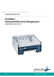
Figure 1: TCA8000 and TCA8500—AC Timing Server, Front View
The front panel of the Timing Server with AC power connector contains the following
components as shown in the Figure 1 on page 4:
•
1–LCD screen
•
2–Selection buttons
•
3–OK button
•
4–MENU button
•
5–Critical alarm LED
•
6–Major alarm LED
•
7–Craft MGMT port
•
8–Minor alarm LED
•
9–Power LED
•
10–REFRESH button
•
11–CANCEL button
The LCD screen displays the applicable menus and the hostname as “Juniper Networks”.
You can change the default IP address of the Timing Server through the craft MGMT port
or by using the buttons. The LEDs display the power status and alarm status of the Timing
Server.
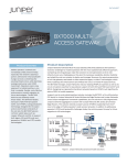
Figure 2: TCA8000 and TCA8500—AC Timing Server, Rear View
The rear panel of the Timing Server with AC power connector contains the following
components as shown in the Figure 2 on page 4:
4
Copyright © 2015, Juniper Networks, Inc.
Chapter 1: TCA8000 and TCA8500 Timing Server Description
•
1–Power switch
•
2–AC power connector
•
3–10 MHz timing output port
•
4–5/1 MHz timing output port
•
5–PPS timing output port
•
6–IRIG-B timing output port
•
7–T1/E1 timing output ports (BITS)
•
8–T1/E1 timing input/output ports (BITS)
•
9–CClock timing output ports
•
10–GPS antenna port
•
11–LAN ports
The power switch is used to switch on or switch off the power of the Timing Server. The
AC power connector is used to supply power to the Timing Server. Timing output ports
are used to deliver 5/1 MHz output signal, 10 MHz output signal, Pulse-per-Second (PPS)
output signal, Inter-Range Instrumentation Group – B (IRIG-B) output signal, T1/E1 output
signal, and CClock output signal. Timing input/output ports are used to receive input
from external T1/E1 sources and provide a timing T1/E1 source outputs. The GPS antenna
port is used to connect the Timing Server with an appropriate GPS L1 antenna. Each LAN
port is an RJ45 connector with synch and activity LEDs. Both the LAN ports can be used
for out-of-band management network connectivity that is Telnet, web interface, and
SNMP. The LAN port “LAN1” is used for the PTP or NTP network connectivity to the Timing
Clients.
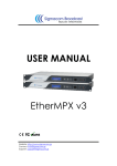
Figure 3: TCA8000 and TCA8500—DC Timing Server, Front View
The front panel of the Timing Server with DC power connectors contains the following
components as shown in the Figure 3 on page 5:
•
1–Retainer screws
•
2–LCD screen
•
3–Selection buttons
•
4–OK button
•
5–MENU button
•
6–Power LED
Copyright © 2015, Juniper Networks, Inc.
5
TCA8000 and TCA8500 Timing Server Installation and Configuration Guide
•
7–Critical alarm LED
•
8–Major alarm LED
•
9–ESD grounding point
•
10–Craft MGMT port
•
11–Minor alarm LED
•
12–ACO button
•
13–REFRESH button
•
14–CANCEL button
•
15–Card ejectors
The LCD screen displays the applicable menus and the hostname as “Juniper Networks”.
You can change the default IP address of the Timing Server through the craft MGMT port
or by using the corresponding buttons. The LEDs display the power status and alarm
status of the Timing Server. The retainer screws are used to secure the removable base
board inside the chassis and the card ejectors are used to gently remove the base board
from the chassis for service. You can clear all alarms set on the device by using the ACO
button.
CAUTION: You must loosen the retainer screws before removing the base
board from the chassis using the card ejectors for any servicing requirement.
CAUTION: To protect the device and its components from electrostatic
damage, wear an antistatic wrist strap and connect it to the ESD grounding
point while handling the device.
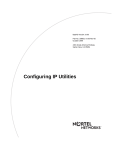
Figure 4: TCA8000 and TCA8500—DC Timing Server, Rear View
The rear panel of the Timing Server with DC power connectors contains the following
components as shown in the Figure 4 on page 6:
6
•
1–DC power terminal B
•
2–IRIG-B timing output port
•
3–10 MHz timing output port
•
4–GPS antenna port
Copyright © 2015, Juniper Networks, Inc.
Chapter 1: TCA8000 and TCA8500 Timing Server Description
•
5–T1/E1 timing input/output ports (BITS)
•
6–Cclock timing output ports
•
7–T1/E1 timing output ports (BITS)
•
8–LAN ports
•
9–DC power terminal A
•
10–PPS timing output port
•
11–5/1 MHz timing output port
Both of the DC terminals have positive, negative, and ground terminals used to connect
a DC power source to the Timing Server. All other components of the DC version Timing
Server performs the same operation as that of the AC version Timing Server.
Copyright © 2015, Juniper Networks, Inc.
7
TCA8000 and TCA8500 Timing Server Installation and Configuration Guide
8
Copyright © 2015, Juniper Networks, Inc.
PART 2
Installing and Setting Up a TCA8000 or
TCA8500 Timing Server
•
Installing and Setting Up a TCA8000 or TCA8500 Timing Server on page 11
Copyright © 2015, Juniper Networks, Inc.
9
TCA8000 and TCA8500 Timing Server Installation and Configuration Guide
10
Copyright © 2015, Juniper Networks, Inc.
CHAPTER 2
Installing and Setting Up a TCA8000 or
TCA8500 Timing Server
This chapter describes the procedure to correctly install the Juniper Networks TCA8000
and TCA8500 Timing Server. The following topics are described:
•
Unpacking the TCA8000 or TCA8500 Timing Server on page 11
•
Requirements for Installing a TCA8000 or TCA8500 Timing Server on page 11
•
Reserving an IP Address for the TCA8000 or TCA8500 Timing Server on page 12
•
Installing the TCA8000 or TCA8500 Timing Server on page 12
•
Recommendations for Mounting the Antenna (TCA8000 or TCA8500 Timing
Server) on page 12
•
Changing the Password of Admin User Account on page 14
•
Assigning an IP Address to the TCA8000 or TCA8500 Timing Server on page 16
•
Visually Testing the TCA8000 or TCA8500 Timing Server With GPS on page 17
•
Verifying the Product T1/E1 Interface Support on page 18
Unpacking the TCA8000 or TCA8500 Timing Server
The Timing Server is shipped with the following items to ensure an optimum installation:
•
TCA8000 or TCA8500 Timing Server
Requirements for Installing a TCA8000 or TCA8500 Timing Server
This section describes the requirements to correctly install and use the TCA8000 or
TCA8500 Timing Server. Table 2 on page 12 lists the items needed to install the Timing
Server.
You must use an appropriate GPS L1 antenna (1575.42 MHz) to receive a minimum GPS
signal from the Timing Server. The antenna must allow a minimum signal input level of
20 dB with respect to the antenna output for the Timing Server.
Copyright © 2015, Juniper Networks, Inc.
11
TCA8000 and TCA8500 Timing Server Installation and Configuration Guide
NOTE: To calculate whether the external antenna, cable type, and length
meets the minimum TCA GPS antenna input, use the following formula:
TCA GPS signal input = antenna gain – [(cable length) * (cable loss / Meter
or Feet)]
Table 2: Antenna Mounting Requirements
Customer Supplied
•
GPS L1 antenna with a frequency band of 1575.42 +/-10 MHz 3 dB bandwidth.
•
Antenna mount
•
Mounting area clear for at least two meters of any metal or other material that could act as a
shield and block the GPS signal
•
160 degree clear view of the sky
•
Clamps, cable ties, and so on, to secure cable
Reserving an IP Address for the TCA8000 or TCA8500 Timing Server
The TCA8000 and TCA8500 Timing Servers support both dynamic and static IP
addressing. If a static address is required, an IP address must be reserved and assigned
for the Timing Server by a network administrator. The DHCP server will always assign a
unique address.
Installing the TCA8000 or TCA8500 Timing Server
Install the Timing Server in a 19-in. or 23-in. rack using the supplied rack mount kit. The
AC system is shipped with the appropriate country power cord and should be connected
to the input plug on the back of the unit. For the DC system the -48 V DC on the back of
unit should be connected to the 48 V DC source.
CAUTION:
For the -48 V DC option:
•
Ground cable—Make a ground cable using 8-gauge wire with the supplied
ground lug. This should attach to your building’s earth ground infrastructure.
•
Power— Route power connection using 18-22 gauge wire to a 48-volt circuit
breaker panel.
Recommendations for Mounting the Antenna (TCA8000 or TCA8500 Timing Server)
This section describes mounting the antenna for the Timing Server at a location where
the unit will receive a GPS signal from several satellites. A site survey is highly
recommended prior to any installation activity. This will determine the best method and
location for mounting the antenna. A site survey will also provide additional information
12
Copyright © 2015, Juniper Networks, Inc.
Chapter 2: Installing and Setting Up a TCA8000 or TCA8500 Timing Server
including cable lengths and required mounting materials in order to perform a secure
and reliable installation.
•
Optimal GPS Antenna Mounting Conditions on page 13
•
Minimal TCA8000 or TCA8500 Timing Server Installation Conditions on page 13
•
Mounting the Antenna on page 13
Optimal GPS Antenna Mounting Conditions
Ideally, the GPS antenna should be mounted where a 160° clear view of the sky (a 10°
angle from horizontal) is available to enable a connection to visible GPS satellites. The
ideal mounting location is a roof, tower or an antenna mast, high above any obstruction
or any device that may cause signal interference. We recommend a location that has the
following characteristics:
•
Clear view of the sky in all directions—at least 270°
•
Away from high-power transmitters and radar antennas
•
At least 3 meters away and at least 1 meter below the highest point of a lightning rod
•
Convenient path for running the outdoor coax cable from the GPS antenna to the
network
Minimal TCA8000 or TCA8500 Timing Server Installation Conditions
The TCA8000 or TCA8500 Timing Server can still maintain accurate time when an
antenna is mounted in a location that has limited visibility of GPS satellites; however, it
is recommended any obstructions should be minimized. Limitations to satellite visibility
for an antenna include overhanging foliage or tall structures. Such structures can block
the GPS signal from the antenna and cause gaps in the GPS satellite signal reception. In
locations where satellite visibility is limited, it is suggested the following be considered:
•
Position the antenna for the Timing Server on the side of the structure with good visibility
toward the equator where more satellites are visible. For example, if you are in the
northern hemisphere, place the unit on the southern side of the structure unless that
view is restricted or blocked. If that view is restricted or blocked, place the unit on the
east or west side of the structure. Avoid the polar side where there are fewer visible
satellites.
•
Ensure that the GMT time zone parameter is set while you configure the Timing Server.
Mounting the Antenna
Follow the manufacturer’s guidelines for the installation of the GPS antenna.
Route the coax cable from the newly installed antenna into the building following the
manufacturer’s antenna safety guidelines.
Route the coax from the building’s ingress to the server’s installation site, and connect
to the GPS server.
Copyright © 2015, Juniper Networks, Inc.
13
TCA8000 and TCA8500 Timing Server Installation and Configuration Guide
WARNING:
•
Locate the TCA8000 or TCA8500 Timing Server away from power lines,
electric lights, and power circuits.
•
When installing the Timing Server, do not touch power lines, or other sources
of live power.
•
Have a qualified technician and or certified electrician perform the
installation.
•
Observe all local and regulatory standards and ordinances.
•
Grounding the unit (metal mast or ground cable to the unit’s base) is
required for the lightning protection to work properly.
Changing the Password of Admin User Account
Juniper Networks assigns a default user account (admin/admin) with login class as
Admin to a TCA8000 or TCA8500 Timing Server for logging in to the Timing Server. You
can create and manage Read-Only or Read/Write user accounts in the TCA8000 or
TCA8500 Timing Server by logging in as admin. For more information about TCA user
account management, see “Managing TCA User Accounts” on page 42 and “TCA User
Accounts Overview” on page 21.
BEST PRACTICE: Before installing the Timing Server on an active network,
change the default password (admin) of the Admin user to maintain secure
access to the Timing Server.
NOTE: You can reset passwords of the Admin user and the enable mode to
factory defaults through the CLI, GUI, or hardware mechanism. For more
information about resetting of passwords, see “Changing/Resetting the Login
Password for Admin User” on page 25 and “Resetting the Passwords of Both
Admin User Account and Enable Mode to Factory Defaults” on page 150.
To change the password of the Admin user, one of the following methods may be used:
•
Configuration through the craft MGMT port on the front panel:
1.
Login as admin.
a. >admin<cr>
b. >password: admin<cr>
2. Enable privileged commands.
a. >enable<cr>
14
Copyright © 2015, Juniper Networks, Inc.
Chapter 2: Installing and Setting Up a TCA8000 or TCA8500 Timing Server
b. >password: enable<cr>
3. Execute the following command to change the Admin user password:
# config password
Please input old password: admin<cr>
Please input new password: admin123<cr>
Please re-type new password: admin123<cr>
•
Configuration from the management interface through the Ethernet port on the back
panel:
1.
Connect a standard Ethernet cable between the Timing Client, LAN1/LAN2, and the
network port of the PC.
2. Launch an Internet browser on your PC.
3. In the URL field, type the following default IP address:
LAN1–http://192.168.0.200
LAN2–http://192.168.1.200
The Timing Server login page appears.
4. In the Login field, enter the following:
admin (Case sensitive—use all “lower” case)
5. In the password field, enter the following:
admin (Case sensitive—use all “lower” case)
6. Click the Login button.
7. Click the Admin tab and locate the Password tab across the top tabs of the Admin
page.
8. In the Hostname field, enter the name assigned to the Timing Server.
9. In the Old Password field, enter the current password of the Admin user.
10. In the New Password field, enter the new password to replace the old password.
11. In the Retype New Password field, reenter the new password.
12. Click the Apply button to save hostname and password changes to the memory.
NOTE: All the examples in this guide use the default password (admin) for
the Admin user.
Copyright © 2015, Juniper Networks, Inc.
15
TCA8000 and TCA8500 Timing Server Installation and Configuration Guide
Assigning an IP Address to the TCA8000 or TCA8500 Timing Server
Juniper Networks assigns a default IP address to a TCA8000 or TCA8500 Timing Server
to allow access to the user interface. The default IP address must be changed before
installing the Timing Server on an active network. To change the IP address, one of the
following methods may be used:
•
Manual entry from the keypad on the front panel.
•
Configuration through the craft MGMT port on the front panel.
•
Configuration from the management interface through the Ethernet port.
To change the IP address through the Ethernet port:
1.
Connect the standard Ethernet cable between the Timing Server, LAN 1/LAN 2 ports
and the network port of the PC.
2. Apply power to the Timing Server.
3. Launch an Internet browser on your PC.
4. In the URL field, type the following default IP address:
LAN1—http://192.168.0.200
LAN2—http://192.168.1.200
The Timing Server login page appears.
5. In the Login field, enter the following:
admin (Case sensitive–use all “lower” case)
6. In the password field, enter the following:
admin (Case sensitive–use all “lower” case)
7. Click the Login button.
8. Click the Config tab if it not already displayed (default).
9. Select the LAN1 option button.
10. Locate Mode in the Network section, and select the Static or DHCP button that will
be used to assign the Timing Server an IP address, and perform one of the following:
a. Select the Static button and enter the following information in the fields above
the Mode selection:
16
•
In the IP Address field, enter the IP address to be assigned to the Timing Server.
•
In the Mask field, enter the subnet mask to be assigned to the Timing Server.
•
In the Gateway field, enter the IP address of the gateway to be assigned to
the Timing Server.
Copyright © 2015, Juniper Networks, Inc.
Chapter 2: Installing and Setting Up a TCA8000 or TCA8500 Timing Server
•
In the Primary DNS field, enter the IP address of the primary DNS to be assigned
to the Timing Server.
NOTE: Leave blank, if not required.
•
In the Secondary DNS field, enter the IP address of the secondary DNS to be
assigned to the Timing Server.
NOTE: Leave blank, if not required.
Apply, save.
b. If the DHCP button is selected, the DHCP server will automatically provide the
Timing Server with IP address information.
Apply, save.
Connect to the network.
c. Contact a network administrator to enable appropriate settings for the following:
•
Speed (100 Mbps, recommended)
•
Duplex (Full-duplex, recommended)
•
Auto negotiation (Disabled, recommended)
Visually Testing the TCA8000 or TCA8500 Timing Server With GPS
1.
Connect the Timing Server and computer to the local network segment and launch
the web browser.
2. Open the Timing Server webpage by using the new IP address (from above), enter
login/password.
3. Click the Status button and observe the System page. The following information
should be present:
•
Model
•
Board S/N
•
System S/N
•
Software version
•
Hardware version
•
FPGA version
•
Temperature
•
MAC addresses for LAN 1 and LAN 2 ports
4. Click the GPS page, and observe the following information:
Copyright © 2015, Juniper Networks, Inc.
17
TCA8000 and TCA8500 Timing Server Installation and Configuration Guide
•
Receiver status = Good
•
Antenna status = Good
•
Satellite status = Acquired
Verifying the Product T1/E1 Interface Support
The TCA8000 or TCA8500 Timing Server ship with both T1 and E1 software images
installed in the two internal non-volatile memory partitions. By default, the TCA8000 or
TCA8500 Timing Server use the E1 interface type. To select the T1 interface type, see
“Upgrading the TCA8000 and TCA8500 Software” on page 59.
18
Copyright © 2015, Juniper Networks, Inc.
PART 3
Configuring and Upgrading the TCA8000
or TCA8500 Timing Server
•
Configuring a TCA8000 or TCA8500 Timing Server on page 21
•
Upgrading the TCA8000 and TCA8500 Software on page 59
Copyright © 2015, Juniper Networks, Inc.
19
TCA8000 and TCA8500 Timing Server Installation and Configuration Guide
20
Copyright © 2015, Juniper Networks, Inc.
CHAPTER 3
Configuring a TCA8000 or TCA8500
Timing Server
This chapter describes the procedure to configure the Juniper Networks TCA8000 and
TCA8500 Timing Servers. The following topics are described in this chapter:
•
TCA User Accounts Overview on page 21
•
Dynamic SSL Certificate Overview on page 23
•
Accessing the User Interface on page 23
•
Requirements for Using the Graphical User Interface on page 24
•
Accessing the Graphical User Interface on page 24
•
Changing/Resetting the Login Password for Admin User on page 25
•
Changing the IP Address on page 27
•
Setting Precision Time Protocol (PTP) Parameters on page 30
•
Setting NTP Parameters on page 32
•
Configuring Alarms on page 36
•
Configuring Traps on page 40
•
Managing TCA User Accounts on page 42
•
Changing the Login Password for Read/Write User on page 44
•
Configuring User Authentication through RADIUS on page 45
•
Configuring RADIUS Accounting on page 49
•
Specifying Recipients for Alarm E-Mail Notifications on page 53
•
Resetting Factory Defaults on page 56
•
Stopping and Restarting the TCA8000 or TCA8500 Timing Server on page 57
TCA User Accounts Overview
Juniper Networks assigns a default user account (admin/admin) with login class as
Admin to a TCA8000 or TCA8500 Timing Server for logging in to the Timing Server. The
user logging in to the Timing Server using the Admin user account can configure the
Timing Server and create, delete or modify user accounts with login class as Read-Only
or Read/Write.
Copyright © 2015, Juniper Networks, Inc.
21
TCA8000 and TCA8500 Timing Server Installation and Configuration Guide
The TCA software supports three predefined login classes to define the access privileges
for the user accounts in your Timing Server. Table 3 on page 22 defines the login classes
predefined in the TCA software.
Table 3: Login Classes for TCA User Accounts
Login Class
Access Privilege
Description
Admin
Create, Delete, or
Modify
User can:
Read/Write
Read-Only
Modify
•
Configure all Timing Server features or parameters through CLI or WEB.
•
View all Timing Server configuration or log details through CLI or WEB.
User can:
Show view
•
Configure Timing Server features or parameters through CLI or WEB except
Admin user functionalities such as creation, deletion, and modifying of user
accounts.
•
View Timing Server configuration or log details through CLI or WEB except some
of the Admin user functionalities such as viewing command history of other
user accounts.
User can:
•
View Timing Server configuration or log details through CLI or WEB except some
of the Admin user functionalities such as viewing command history of other
user accounts.
The TCA software creates a separate log file for each user account to store the commands
executed by the corresponding user. The software stores the session ID and timestamp
in the log file to identify the various sessions for that particular user. The software deletes
the log file created for the user account, when the Admin user deletes any Read-Only or
Read/Write user account.
NOTE: The software can store only a maximum of 150 commands in a log
file.
Guidelines for User Account Management
Keep in mind the following considerations when you (Admin) configure user accounts:
22
•
The software supports only five user accounts.
•
You cannot delete the default Admin user account assigned by Juniper Networks.
•
You cannot create another Admin user account.
•
The username should be 4 to 12 characters long. The characters can only include
alphanumeric and underscore. No other special characters are allowed.
•
The username should be unique.
•
The password should be 4 to 12 characters long. The characters can include
alphanumeric and special characters (that is, !@#$_).
Copyright © 2015, Juniper Networks, Inc.
Chapter 3: Configuring a TCA8000 or TCA8500 Timing Server
Dynamic SSL Certificate Overview
The TCA 8000 or 8500 Timing Server enables you to access the GUI through Hypertext
Transfer Protocol (HTTP) or Hypertext Transfer Protocol over Secure Sockets Layer
(HTTPS) based on the web mode configured by the Admin user. The Admin user can
configure the Timing Server to use the customized key and certificate instead of the
default key and certificate, when the GUI is accessed through HTTPS. By default, the
Timing Server uses the default key and certificate when the GUI is accessed through
HTTPS.
The Admin user can download the customized key and certificate files of .pem format
in the Timing Server through CLI or GUI. The downloaded key file is stored as an
ssl_key.pem file in the etc/config path. The downloaded certificate file is stored as an
ssl_cert.pem file in the etc/config path. The Admin user can generate the customized
files by using OpenSSL or FIPS 140-2 capable OpenSSL as trusted certification authority.
For complete information and source of OpenSSL utility, see http://www.openssl.org/.
When you access the GUI through HTTPS, the Timing Server checks for the ssl_key.pem
and ssl_cert.pem files in the etc/config path. If any one of the files is not available, the
Timing Server uses the default key and certificate. If the files are available, the Timing
Server checks the BEGIN header and the END footer in both the files. If the header and
footer are valid in both the files, the Timing Server compares the key file with the certificate
file. On successful match, the Timing Server loads the GUI and generates a syslog.
The Timing Server does not load the GUI but generates a syslog during the following
scenarios:
•
Mismatch identified between the key and certificate files.
•
Invalid header or footer identified in one of the files.
•
Validity of any file got expired.
The Admin user must keep the following conditions in mind when downloading the
customized files:
•
After downloading both the files, you must reboot the Timing Server for the changes
to take effect.
•
The Timing Server uses the default key and certificate if both or any one of the
customized files is unavailable.
•
You cannot modify the downloaded files but you can replace them with another ones.
•
You should use only Secure Hash Algorithm (SHA-1) and RSA (1024 bits) cryptographic
algorithms while generating the customized key and certificate files.
Accessing the User Interface
You can configure the TCA8000 or TCA8500 Timing Server using one of the following
methods:
Copyright © 2015, Juniper Networks, Inc.
23
TCA8000 and TCA8500 Timing Server Installation and Configuration Guide
•
Graphical user interface (GUI)
•
Telnet
•
Secured shell (SSH)
This chapter describes how to access the GUI. Accessing the Timing Server using Telnet
and SSH is described in
“Using Telnet with the TCA8000 and TCA8500 Timing Servers” on page 149.
Requirements for Using the Graphical User Interface
To use the TCA8000 or TCA8500 GUI, log in to the embedded Web server with an
Internet browser. The following browsers and versions are supported:
•
Internet Explorer version 6.x or later
•
Firefox version 1.5.0.7 or later (Firefox 3.0 is currently not supported)
Accessing the Graphical User Interface
To access the GUI:
1.
Open an Internet browser.
2. In the address or URL field enter the IP address assigned to the Timing Server to be
accessed, using the following command:
http://ip_address
The Login page appears. See Figure 5 on page 24.
Figure 5: TCA8000 or TCA8500 Timing Server Login Page
3. In the Username field enter the username that you want to use to log in to the server.
NOTE: The default username assigned by the Juniper Networks is admin.
You cannot change the default username. You can create new user
accounts from the config page by logging in as Admin user.
24
Copyright © 2015, Juniper Networks, Inc.
Chapter 3: Configuring a TCA8000 or TCA8500 Timing Server
4. In the Password field enter the password required to log in to the server.
NOTE: The default password assigned by the Juniper Networks is admin.
You can change the log in password of the Admin user from the Admin
page.
5. Click the Login button. The Status page appears. See Figure 6 on page 25.
Figure 6: Timing Server Status Page—System Pane
The Timing Server GUI will automatically time out after 5 minutes of inactivity. The
login and password will have to be reentered to gain access to the unit.
Changing/Resetting the Login Password for Admin User
We recommend that the TCA8000 or TCA8500 Timing Server login password of the
Admin user be changed from the manufacturer set default to maintain secure access to
the server.
Copyright © 2015, Juniper Networks, Inc.
25
TCA8000 and TCA8500 Timing Server Installation and Configuration Guide
To change the login password of the Admin user:
1.
Click the Admin tab.
The Admin page—Password pane appears. See Figure 7 on page 26.
NOTE: The Admin tab is visible only to the Admin user.
Figure 7: Timing Server Admin Page—Password Pane
2. In the Hostname field of the System Name & Password section, enter the hostname
to be assigned to the Timing Server.
3. In the Old Password field, enter the current admin password.
4. In the New Password field, enter the password that you want to use.
NOTE: Passwords are case sensitive and accept alphanumeric characters.
Passwords must contain a minimum of four characters.
5. In the Retype New Password field, enter the password that you want to use.
6. Click the Apply button.
To reset passwords of the Admin user and the enable mode to factory defaults:
1.
Click the Admin tab.
The Admin page—Password pane appears. See Figure 7 on page 26.
NOTE: The Admin tab is visible only to the Admin user.
2. Select the Password Recovery check box.
3. Click the Apply button to reset passwords of the Admin user and the enable mode to
factory defaults.
26
Copyright © 2015, Juniper Networks, Inc.
Chapter 3: Configuring a TCA8000 or TCA8500 Timing Server
NOTE: If you have forgotten the password of the Admin user, you can
reset the password to factory default through hardware mechanism. For
more information about resetting the password through hardware
mechanism, see “Resetting the Passwords of Both Admin User Account
and Enable Mode to Factory Defaults” on page 150.
Changing the IP Address
The TCA8000 and TCA8500 Timing Servers are configured to use the manufacturer’s
default static IP addresses assigned to the Ethernet ports. Use the user interface to
manually change the IP addresses of the Ethernet ports and configure or change VLAN
settings for the Ethernet ports.
NOTE: You cannot configure Ethernet and VLAN port addresses to be in the
same subnet (that is, all logical and physical interfaces should be configured
to be in different subnets).
To change the address information for Ethernet ports:
1.
Click the Config tab. The Config page appears. See Figure 8 on page 29.
2. In the Mode field, click the Static button to activate the address fields.
3. In the IP Address field, enter the IP address that you want the Timing Server to use.
NOTE: After you save the IP address change, you must launch the Timing
Server user interface using the new IP address to view and configure the
current settings.
4. In the Mask field, enter the subnet mask that you want the Timing Server to use.
5. In the Gateway field, enter the IP address of the gateway with which you want the
Timing Server to register.
6. In the Primary DNS field, enter the IP address of the Primary DNS with which you want
to register the Timing Server.
7. In the Secondary DNS field, enter the IP address of the Secondary DNS with which
you want to register the Timing Server.
8. To determine whether an IP address is currently assigned, enter the IP address in the
Ping field and click Go. If the ping goes through, then the IP address is already taken.
Otherwise, it is not assigned, and can be used by the Timing Server.
9. Click the Apply button to save and implement the changes.
Copyright © 2015, Juniper Networks, Inc.
27
TCA8000 and TCA8500 Timing Server Installation and Configuration Guide
To configure or change VLAN settings for the Ethernet ports:
1.
Click the Config tab. The Config page appears. See Figure 8 on page 29.
2. In the LAN field, select a LAN (LAN1 or LAN2) for which VLAN settings to be configured.
3. In the Mode field, select the Static option button to activate the VLAN address fields.
4. In the VLAN field, select a VLAN (VLAN1 or VLAN2) for which settings should be
configured.
5. In the IP Address field, enter the IP address for the selected VLAN.
6. In the Mask field, enter the subnet mask assigned to the selected VLAN.
7. In the Id field, enter a unique identifier in the range 2 through 4095 that is used to
identify the VLAN encapsulation packet.
NOTE: If the ID you have entered is already being used by any other VLAN,
a warning message is displayed.
8. In the Priority field, enter a priority value for the VLAN header to be used for differential
services transporting the packet.
9. In the Enable field, select the Yes option button to enable VLAN encapsulation for IP
packets, or select the No option button to disable VLAN encapsulation for IP packets.
10. Click Apply to save and implement the changes.
28
Copyright © 2015, Juniper Networks, Inc.
Chapter 3: Configuring a TCA8000 or TCA8500 Timing Server
Figure 8: Timing Server Config Page—Network Pane
Copyright © 2015, Juniper Networks, Inc.
29
TCA8000 and TCA8500 Timing Server Installation and Configuration Guide
Setting Precision Time Protocol (PTP) Parameters
Figure 9: Timing Server Config Page—PTP Pane
30
Copyright © 2015, Juniper Networks, Inc.
Chapter 3: Configuring a TCA8000 or TCA8500 Timing Server
NOTE: You can view this pane only if the PTP support is enabled in the Timing
Server.
The PTP pane on the Configuration page allows you to set parameters to be part of a
distributed synchronous network using Precision Time Protocol (PTP). To configure the
TCA8000 or TCA8500 Timing Server to provide time synchronization:
1.
Click the Config tab. The Config page appears.
2. Locate the PTP tab across the top of the Config page. See Figure 9 on page 30.
3. In the Profile field, select “Default” profile to use multicast PTP messages only, or
“Juniper Type 1” profile to use multicast PTP messages for Announce and Sync, and
unicast messages for Delay Request and Delay Response.
4. In the Priority 1 and Priority 2 fields, enter a value within the range of 0 through 254
to configure the priorities of each master for proper Best Master Clock (BMC) algorithm
operation.
5. The Domain Number field specifies the domain number which the TCA8000 or
TCA8500 Timing Server has been assigned to. Enter a value within the range of 0
through 254 to configure the PTP domain for the Timing Server, which then becomes
a synchronization reference source to all the slave clocks within the same domain
using the PTP protocol.
6. In the Two Step field, select “no” to enable One-Step clock, or select “yes” to enable
Two-Step clock.
7. In the Log Mean Delay Req Interval field, select a minimum mean time interval at
which you want the Timing Server to respond to successive Delay Request packets
from a slave clock. The default value is 8 pps.
8. In the Log Mean Announce Interval field, select a mean time interval between
successive Announce messages. The default value is 1 pps.
9. In the Log Mean Sync Interval field, select a mean time interval between successive
Sync messages. The default value is 32 pps.
10. Announce Receipt Timeout. The default value is 3.
11. In the DSCP field, enter the Differential Service (DiffServ) value for the IP packet.
12. In the Telecom Standard field, select a telecom standard to be implemented with
the telecom profile for advertising the announce message. The default value is
Telecom-IEEE1588.
13. In the Announce Start Timeout field, enter a value within the range of 0 through 120
minutes. On rebooting, the TCA Timing Server delays the transmission of announce
messages either until any configured synchronization source is locked to the frequency
within the configured timeout value or until the expiry of the configured timeout value.
14. Click the Apply button to save the PTP parameter changes.
Copyright © 2015, Juniper Networks, Inc.
31
TCA8000 and TCA8500 Timing Server Installation and Configuration Guide
To configure the unicast related parameters:
1.
From the Delay Range lists, select the range (minimum and maximum) of delay
request or response event message rate from the options: 1 packet/sec, 2 packet/sec,
4 packet/sec, 8 packet/sec, 16 packet/sec, 32 packet/sec, and 64 packet/sec.
2. From the Announce Range lists, select the range (minimum and maximum) of
announce interval message rate from the options: 1 packet/1 sec, 1packet/2 sec, 1
packet/4 sec, and 1 packet/8 sec.
3. From the Sync Interval lists, select the range (minimum and maximum) of sync event
message rate from the options: 1 packet/sec, 2 packet/sec, 4 packet/sec, 8
packet/sec, 16 packet/sec, 32 packet/sec, and 64 packet/sec.
4. Click the Apply button to save the unicast parameter changes.
To add the Timing Clients (Slaves) for the Timing Server:
1.
In the IP Address field, enter the IP address of the Timing Client (Slave) through which
the Grandmaster sends or receives event messages.
2. Click the Add button to add the Timing Client entry in the Slave List window.
To delete the Timing Client entry:
1.
Select the Timing Client entry that you want to delete from the Slave List window.
2. Click the Delete button to delete the entry or click the Clear All button to delete all
the entries from the Slave List window.
Setting NTP Parameters
The TCA8000 and TCA8500 Timing Servers support using the NTP to synchronize time.
You can define the NTP association details and the MD5 key list to configure NTP.
•
Enabling the NTP Support on page 32
•
Creating an NTP Association Entry on page 34
•
Modifying an Existing NTP Association Entry on page 35
•
Deleting an Existing NTP Association Entry on page 35
•
Configuring the MD5 Key List on page 35
Enabling the NTP Support
The Config pane on the Admin page enables you to configure the protocol (NTP or PTP)
to be used for time synchronization. By default, the PTP support is enabled in the Timing
Server.
To enable the NTP support in the Timing Server:
1.
Log in to the Timing Server as Admin user.
2. Click the Admin tab.
32
Copyright © 2015, Juniper Networks, Inc.
Chapter 3: Configuring a TCA8000 or TCA8500 Timing Server
3. Locate the Config tab across the top tabs of the Admin page. See Figure 10 on page 33.
Figure 10: Timing Server Admin Page—Config Pane
4. In the PTP/NTP Config field, select the NTP option button.
5. Click the Apply button.
A dialog box stating “System reboot is required to make changes effective. Do you
want to reboot?” is displayed.
6. Click Yes to reboot the Timing Server with the NTP support.
Copyright © 2015, Juniper Networks, Inc.
33
TCA8000 and TCA8500 Timing Server Installation and Configuration Guide
NOTE:
• If you reject the rebooting of the Timing Server, the protocol change is
not saved and the Timing Server continues to use the PTP.
•
After rebooting, you cannot use the PTP commands and panes for
configuring PTP functionalities. To configure PTP functionalities by
using the PTP panes and CLI commands, you must enable the PTP
support and reboot the Timing Server.
Creating an NTP Association Entry
To create a new NTP association entry:
NOTE: You can add only a maximum of 20 NTP association entries. Each
NTP association entry should have a unique IPv4 address configured.
1.
Log in to the Timing Server as Admin or Read/Write user.
2. Click the Config tab.
3. Locate the NTP tab across the top tabs of the Config page. See Figure 11 on page 34.
Figure 11: Timing Server Config Page—NTP Pane
NOTE: You can view this pane only if the NTP support is enabled in the
Timing Server.
34
Copyright © 2015, Juniper Networks, Inc.
Chapter 3: Configuring a TCA8000 or TCA8500 Timing Server
4. From the Mode list, select the NTP operation mode for the association entry.
5. In the Address field, enter the IPv4 address for the association entry. The IPv4 address
depends on the value selected from the Mode list.
Mode
Valid IPv4 Address
Broadcast
Class D or broadcast address of a local interface.
Manycast Server
Class D
6. From the Version list, select the version to be used for the outgoing NTP packets. This
list appears dimmed if you have selected the Manycast Server mode.
7. From the Key list, select the key identifier used for encryption.
8. In the Time to live field, enter the number of hops for the NTP packets. This field
appears dimmed if you have selected the Manycast Server mode.
9. Click the Save button to create a new NTP association entry.
Modifying an Existing NTP Association Entry
To modify an existing NTP association entry:
1.
Log in to the Timing Server as Admin or Read/Write user.
2. Click the Config tab.
3. Locate the NTP tab across the top tabs of the Config page. See Figure 11 on page 34.
4. In the Current NTP Association window, select the association entry to be modified.
5. Click the Edit button to populate details of the selected association entry in the fields
in the Add/Edit NTP Association section.
6. Modify the applicable parameters for the selected association entry.
7. Click the Save button to save the changes.
Deleting an Existing NTP Association Entry
To delete an existing NTP association entry:
1.
Log in to the Timing Server as Admin or Read/Write user.
2. Click the Config tab.
3. Locate the NTP tab across the top tabs of the Config page. See Figure 11 on page 34.
4. In the Current NTP Association window, select the association entry to be deleted.
5. Click the Delete button to delete the selected association entry.
Configuring the MD5 Key List
To configure the MD5 key list:
Copyright © 2015, Juniper Networks, Inc.
35
TCA8000 and TCA8500 Timing Server Installation and Configuration Guide
1.
Log in to the Timing Server as Admin or Read/Write user.
2. Click the Config tab.
3. Locate the MD5 tab across the top tabs of the Config page. See Figure 12 on page 36.
Figure 12: Timing Server Config Page—MD5 Pane
NOTE: You can view this pane only if the NTP support is enabled in the
Timing Server.
4. Configure the MD key list:
a. Click the Generate button to generate MD5 key list by using the system command
ntp-keygen.
or
b. Click the Browse button to locate a file containing new MD5 keys and click the
Upload button to upload the new keys.
Configuring Alarms
You can specify how you want the TCA8000 or TCA8500 Timing Server to handle alarms
that occur during operation. To configure the alarms:
1.
Click the Admin tab. The Admin page appears.
2. Click the Alarm Profile tab. See Figure 13 on page 38 and Figure 14 on page 39.
36
Copyright © 2015, Juniper Networks, Inc.
Chapter 3: Configuring a TCA8000 or TCA8500 Timing Server
3. For each alarm, the following parameters can be configured:
a. Select the Clear Now check box to clear the alarm right away.
b. Select the Auto Clear check box to clear the alarm after it happens for 24 hours.
c. In the Severity field, select the flag to accompany this alarm. Select:
•
Critical—Indicates this alarm needs immediate attention, and is affecting the
normal operation of the Timing Server.
•
Major—Indicates this alarm needs immediate attention.
•
Minor—Indicates this alarm needs attention but is not urgent.
•
None—Indicates this alarm is for information only.
d. Select the Send Trap check box. The Timing Server will send the alarm to the Trap
destinations identified on the Config page.
e. Select the Write Log check box. The Timing Server will send the alarm to the local
log file.
f.
Select the Send to Email check box. The Timing Server will send an e-mail message
about this alarm to the users identified in the Alarm E-mail Recipients section of
the Alarm tab.
Copyright © 2015, Juniper Networks, Inc.
37
TCA8000 and TCA8500 Timing Server Installation and Configuration Guide
Figure 13: Timing Server Admin Page—Alarm Pane (PTP)
38
Copyright © 2015, Juniper Networks, Inc.
Chapter 3: Configuring a TCA8000 or TCA8500 Timing Server
Figure 14: Timing Server Admin Page—Alarm Pane (NTP)
Copyright © 2015, Juniper Networks, Inc.
39
TCA8000 and TCA8500 Timing Server Installation and Configuration Guide
Configuring Traps
The TCA8000 and TCA8500 Timing Servers can be configured to send event information
to trap destinations on a network.
•
Specifying SNMPv3 Contacts on page 40
•
Creating Trap Targets on page 41
•
Deleting Trap Targets on page 41
•
Creating SNMPv3 Users on page 41
Specifying SNMPv3 Contacts
You can configure the TCA8000 or TCA8500 Timing Server to send alarm information
to SNMP community files. To configure the Timing Server to send information to
community files:
1.
Click the Config tab. The Config page appears.
2. Locate the Trap tab at the top right of the page. See Figure 15 on page 40.
3. In the sysLocation field, enter the location of the Timing Server.
4. In the sysName field, enter the name used to identify the Timing Server.
5. In the sysContact field, enter the X-address of the manager that you want the Timing
Server to use.
6. In the ReadOnlyComm field, enter the string that you want the Timing Server to use
to access the local SNMP read community.
7. In the RWriteComm field, enter the string that you want the Timing Server to use to
access the local SNMP write community.
8. Click Apply to save changes.
Figure 15: Timing Server Config Page—Trap Pane
40
Copyright © 2015, Juniper Networks, Inc.
Chapter 3: Configuring a TCA8000 or TCA8500 Timing Server
Creating Trap Targets
To create a Trap destination (see Figure 15 on page 40):
1.
Click the Config tab.
2. Locate the Trap tab across the top of the Config page.
3. In the Address field, enter the IP address or domain name to which you want the
Timing Server event information sent.
4. In the Version area, select the option button for the version of SNMP that this trap
supports.
5. Click the Save button to save your changes.
Deleting Trap Targets
To delete a Trap destination:
1.
Click the Config tab.
2. Locate the Trap tab across the top tabs of the Config page.
3. Click the Trap address that you want deleted.
4. Click the Delete button to remove the entry from the Trap pane.
Creating SNMPv3 Users
The TCA8000 and TCA8500 Timing Servers support security measures in SNMPv3. To
create SNMPv3 users:
1.
Click the Config tab. The Config page appears.
2. Click the SNMPv3 section across the top of the Config page. See Figure 16 on page 42.
3. In the Name field, enter the username that will be used to log into SNMPv3 log files.
4. In the Auth Phrase field, enter the authentication phrase you want this user to use.
5. In the Auth Crypt area, select the encryption method that you want this user to use.
6. In the Pri Phrase field, enter the private phrase that you want this user to use if required.
7. In the Pri Protocol field, select the privilege level that you want this user to use. Select:
•
DES—The user must use the authentication phrase to log in.
•
AES—The user is not required to use the authentication phrase to log in.
•
No Privacy—The user is required to use the authentication phrase and the private
phrase to log in.
8. Click the Save button to save the user information in the V3User window.
Copyright © 2015, Juniper Networks, Inc.
41
TCA8000 and TCA8500 Timing Server Installation and Configuration Guide
Figure 16: Timing Server Config Page—SNMPv3 Pane
Managing TCA User Accounts
The TCA8000 and TCA8500 Timing Servers support multiple user accounts to be created
and managed by the Admin user. Juniper Networks assigns a default user account
(admin/admin) with login class as Admin to a TCA8000 or TCA8500 Timing Server for
logging in to the Timing Server. This Admin user account allows the administrator to
create and manage multiple user accounts with login class as Read-Only and Read/Write.
The TCA user accounts can be managed by:
•
Creating an User Account on page 42
•
Modifying an Existing User Account on page 43
•
Deleting an Existing User Account on page 44
Creating an User Account
To create a new user account:
NOTE: You can create only a maximum of five user accounts.
1.
Log in to the Timing Server as Admin user.
2. Click the Config tab.
3. Locate the Users tab across the top tabs of the Config page. See Figure 17 on page 43.
42
Copyright © 2015, Juniper Networks, Inc.
Chapter 3: Configuring a TCA8000 or TCA8500 Timing Server
Figure 17: Timing Server Config Page—Users Pane
4. In the Username field, enter the username for the new user account.
5. In the Password field, enter the password for the new user account.
6. In the Class field, select an option button to set the login class for the new user account
as Read-Only or Read/Write.
7. Click the Save button to create a new user account.
Modifying an Existing User Account
To modify an existing user account:
NOTE: You cannot modify the username.
1.
Log in to the Timing Server as Admin user.
2. Click the Config tab.
3. Locate the Users tab across the top tabs of the Config page. See Figure 17 on page 43.
4. In the Users window, select the user account to be modified.
5. Click the Edit button to populate the details of the selected user account in the
Username, Password, and Class fields.
6. Modify the password or class for the selected user account.
Copyright © 2015, Juniper Networks, Inc.
43
TCA8000 and TCA8500 Timing Server Installation and Configuration Guide
NOTE:
• If you change the password, all the active sessions for the corresponding
user are not logged out. The user must use the new password for new
sessions.
•
If you change the class, all active sessions for the corresponding user
are logged out.
7. Click the Save button to save the changes done.
Deleting an Existing User Account
To delete an existing user account:
1.
Log in to the Timing Server as Admin user.
2. Click the Config tab.
3. Locate the Users tab across the top tabs of the Config page. See Figure 17 on page 43.
4. In the Users window, select the user account to be deleted.
5. Click the Delete button to delete the selected user account.
NOTE: All active sessions for the deleted user are logged out.
Changing the Login Password for Read/Write User
The TCA8000 and TCA8500 timing servers allow Read/Write users to change their
password configured and shared by the TCA Admin user.
To change your (Read/Write user) password:
1.
Log in to the Timing Server as Read/Write user.
2. Click the Config tab.
3. Locate the Profile tab across the top tabs of the Config page. See Figure 18 on page 45.
44
Copyright © 2015, Juniper Networks, Inc.
Chapter 3: Configuring a TCA8000 or TCA8500 Timing Server
Figure 18: Timing Server Config Page—Profile Pane
4. In the Old Password field, enter your current password.
5. In the New Password field, enter the new password to replace the old password.
6. In the Retype New Password field, reenter the new password.
7. Click Save button to change your password and save the changes.
NOTE: The new password will be effective from next login onwards. The
current session is not affected.
Configuring User Authentication through RADIUS
The TCA 8000 and TCA 8500 Timing Servers support RADIUS server authentication,
local authentication, or both based on the configured authentication order to authenticate
the user logging in to the Timing Server.
When you configure the authentication order as RADIUS server authentication followed
by the local authentication, the Timing Server passes the information about the logging
user to the configured RADIUS servers for authentication. If any one of the RADIUS server
successfully authenticates the user, then the Timing Server allows the user to login. If all
the configured RADIUS servers fail to authenticate the user or configured RADIUS servers
are not available, then the Timing Server performs the local authentication and allows
the user to login after successful local authentication. The Timing Server blocks the
logging user if both RADIUS and local authentication fails.
When you configure the authentication order as local authentication followed by the
RADIUS server authentication, the Timing Server performs the local authentication to
grant access to the logging user. If the local authentication fails to authenticate the user,
then the Timing Server passes the information about the logging user to the configured
Copyright © 2015, Juniper Networks, Inc.
45
TCA8000 and TCA8500 Timing Server Installation and Configuration Guide
RADIUS servers for authentication. If any one of the RADIUS server successfully
authenticates the user, then the Timing Server allows the user to login. If all configured
RADIUS servers fail to authenticate the user, then the Timing Server denies access to
the logging user.
When you configure the authentication order as RADIUS server authentication only, the
Timing Server passes the information about the logging user to the configured RADIUS
servers for authentication. If any one of the RADIUS server successfully authenticates
the user, then the Timing Server allows the user to login. If all configured RADIUS servers
fail to authenticate the user, then the Timing Server denies access to the logging user. If
all configured RADIUS servers are not available, then the Timing Server performs local
authentication and allows the user to login after successful local authentication.
When you configure the authentication order as local authentication only, the Timing
Server performs the local authentication to grant or deny access to the user logging in
to the Timing Server.
NOTE:
•
The selection of RADIUS authentication server to authenticate user is based
on the order in the RADIUS authentication server list.
•
The user authentication process is implemented only for the Access
Request, Access Reject, and Access Accept messages.
•
The user authentication process is not supported for shell users.
The user authentication process protects the Timing Server from being accessed by
unauthorized persons. The usage of RADIUS authentication servers provides the following
advantages:
•
Management of multiple user credentials on remote machine for detailed logging.
•
Centralized user information and authentication process at one server.
•
No loss of user information due to Timing Server damage.
To configure user authentication process:
1.
Click the Config tab.
2. Locate the RADIUS tab across the top tabs of the Config page. See
Figure 19 on page 47.
46
Copyright © 2015, Juniper Networks, Inc.
Chapter 3: Configuring a TCA8000 or TCA8500 Timing Server
Figure 19: Timing Server Config Page—RADIUS Pane (Authentication)
3. Configure the RADIUS authentication server details.
4. Click the Save button to save the authentication server configuration.
5. Select the authentication order.
6. Click the Apply button to apply the configured authentication order.
The following sections describe RADIUS authentication server configuration and
authentication order configuration:
•
Adding a New RADIUS Authentication Server Entry on page 48
•
Deleting a RADIUS Authentication Server Entry on page 48
Copyright © 2015, Juniper Networks, Inc.
47
TCA8000 and TCA8500 Timing Server Installation and Configuration Guide
•
Modifying RADIUS Authentication Server Entry Details on page 48
•
Configuring Authentication Order on page 49
Adding a New RADIUS Authentication Server Entry
To add a new RADIUS authentication server entry to the authentication server list:
1.
Click the Config tab.
2. Locate the RADIUS tab across the top tabs of the Config page. See
Figure 19 on page 47.
3. In the Server IP field, enter the IP address of the RADIUS authentication server to be
used for user authentication.
4. In the Port field, enter the port through which the specified RADIUS authentication
server is contacted for user authentication.
5. In the Retry field, enter the number of attempts should be made for contacting the
specified RADIUS authentication server.
6. In the Timeout field, enter the time in seconds till which the Timing Server waits for
a response from the specified RADIUS authentication server.
7. In the Secret Word field, enter the password shared with the specified RADIUS
authentication server.
8. Click the Save button to add the RADIUS authentication server entry in the RADIUS
Authentication Servers window and memory.
Deleting a RADIUS Authentication Server Entry
To delete a RADIUS authentication server entry from the authentication server list:
1.
Click the Config tab.
2. Locate the RADIUS tab across the top tabs of the Config page. See
Figure 19 on page 47.
3. In the RADIUS Authentication Servers window, click the RADIUS authentication
server entry to be deleted.
4. Click the Delete button to remove the entry from the RADIUS Authentication Server
window and memory.
Modifying RADIUS Authentication Server Entry Details
To modify the details of a RADIUS authentication server entry existing in the authentication
server list:
1.
Click the Config tab.
2. Locate the RADIUS tab across the top tabs of the Config page. See
Figure 19 on page 47.
48
Copyright © 2015, Juniper Networks, Inc.
Chapter 3: Configuring a TCA8000 or TCA8500 Timing Server
3. In the RADIUS Authentication Servers window, select the RADIUS authentication
server entry to be modified.
4. Click the Edit button to populate the values of the selected RADIUS authentication
server entry in the Server IP, Port, Retry, Timeout, and Secret Word fields.
5. Modify the populated values.
6. Click the Save button to save the changes done in the selected RADIUS authentication
server entry.
Configuring Authentication Order
To configure the authentication order:
1.
Click the Config tab.
2. Locate the RADIUS tab across the top tabs of the Config page. See
Figure 19 on page 47.
3. In the first drop box, select the type of authentication to be performed initially. Select:
•
radius—To authenticate the user using the configured RADIUS authentication
servers.
•
local—To authenticate the user using local settings.
4. In the second drop box, select the type of authentication to be performed on failure
or unavailability of initial authentication. Select:
•
radius—To authenticate the user using the configured RADIUS authentication
servers.
•
local—To authenticate the user using local settings.
5. Click the Apply button to save the authentication order.
Configuring RADIUS Accounting
The TCA 8000 and TCA 8500 Timing Servers support RADIUS accounting for the user
logged in to the Timing Server. Once the user is logged in to the Timing Server, the Timing
Server passes the accounting information to the configured RADIUS accounting servers.
The Timing Server stops the accounting process when the user session is closed either
voluntarily or involuntarily. The Timing Server waits for acknowledgment from the
accounting servers for each accounting packet.
When the RADIUS accounting is enabled, the Timing Server tries to log the accounting
information in any one of the configured RADIUS accounting server based on the
configured timeout period and number of retries. When the logging of accounting
information fails for all configured accounting server, the Timing Server raises an
ACCOUNTING_SERVER_UNAVAILABLE alarm.
When the RADIUS accounting server is unavailable, the accounting information (latest
15 commands) is buffered. The Timing Server sends the buffered information to the
RADIUS accounting server after the server becomes available.
Copyright © 2015, Juniper Networks, Inc.
49
TCA8000 and TCA8500 Timing Server Installation and Configuration Guide
The accounting process supports login accounting, interactive commands accounting,
and configuration commands accounting.
NOTE:
•
The selection of RADIUS accounting server to log the accounting
information is based on the order in the RADIUS accounting server list.
•
The accounting process is implemented only for the Accounting Request
and Accounting Response messages.
•
The RADIUS accounting is not supported for shell users.
•
The accounting process does not support immediate accounting and
accounting of web configurations.
The usage of RADIUS accounting servers provides the following advantages:
•
Centralized usage history of all users on one server.
•
No loss of usage history of users due to Timing Server damage.
To configure RADIUS accounting:
1.
Click the Config tab.
2. Locate the RADIUS tab across the top tabs of the Config page. See
Figure 20 on page 51.
50
Copyright © 2015, Juniper Networks, Inc.
Chapter 3: Configuring a TCA8000 or TCA8500 Timing Server
Figure 20: Timing Server Config Page—RADIUS Pane (Accounting)
3. In the RADIUS Accounting Status field, select the Enable option to enable RADIUS
accounting.
4. Click the Apply button to apply RADIUS accounting status configuration.
5. Configure the RADIUS accounting server details
6. Click the Save button to save the accounting server configuration.
Copyright © 2015, Juniper Networks, Inc.
51
TCA8000 and TCA8500 Timing Server Installation and Configuration Guide
7. In the RADIUS Accounting Level field, select the type of accounting information to
be logged in the RADIUS accounting server.
8. Click the Apply button to apply the configured RADIUS accounting level.
The following section describe RADIUS accounting server configuration:
•
Adding a New RADIUS Accounting Server Entry on page 52
•
Deleting a RADIUS Accounting Server Entry on page 52
•
Modifying RADIUS Accounting Server Entry Details on page 53
Adding a New RADIUS Accounting Server Entry
To add a new RADIUS accounting server entry to the accounting server list:
1.
Click the Config tab.
2. Locate the RADIUS tab across the top tabs of the Config page. See
Figure 20 on page 51.
3. In the Server IP field, enter the IP address of the RADIUS accounting server to be used
for accounting.
4. In the Port field, enter the port through which the specified RADIUS accounting server
is contacted for accounting.
5. In the Retry field, enter the number of attempts should be made for contacting the
specified RADIUS accounting server.
6. In the Timeout field, enter the time in seconds till which the Timing Server waits for
a response from the specified RADIUS accounting server.
7. In the Secret Word field, enter the password shared with the specified RADIUS
accounting server.
8. Click the Save button to add the RADIUS accounting server entry in the RADIUS
Accounting Servers window and memory.
Deleting a RADIUS Accounting Server Entry
To delete a RADIUS accounting server entry from the accounting server list:
1.
Click the Config tab.
2. Locate the RADIUS tab across the top tabs of the Config page. See
Figure 20 on page 51.
3. In the RADIUS Accounting Servers window, click the RADIUS accounting server entry
to be deleted.
4. Click the Delete button to remove the entry from the RADIUS Accounting Servers
window and memory.
52
Copyright © 2015, Juniper Networks, Inc.
Chapter 3: Configuring a TCA8000 or TCA8500 Timing Server
Modifying RADIUS Accounting Server Entry Details
To modify the details of a RADIUS accounting server entry existing in the accounting
server list:
1.
Click the Config tab.
2. Locate the RADIUS tab across the top tabs of the Config page. See
Figure 20 on page 51.
3. In the RADIUS Accounting Servers window, select the RADIUS accounting server
entry to be modified.
4. Click the Edit button to populate the values of the selected RADIUS accounting server
entry in the Server IP, Port, Retry, Timeout, and Secret Word fields.
5. Modify the populated values.
6. Click the Save button to save the changes done in the selected RADIUS accounting
server entry.
Specifying Recipients for Alarm E-Mail Notifications
The TCA8000 and TCA8500 Timing Servers can e-mail alarm event messages directly
to users.
•
Adding a User to the E-Mail List on page 53
•
Removing a User from the Alarm Event Recipient List on page 56
Adding a User to the E-Mail List
To add a user to the list of e-mail recipients to whom the Timing Server sends alarm
events:
1.
Click the Admin tab.
2. Locate the Alarm section across the top of the Admin page. See Figure 21 on page 54
and Figure 22 on page 55.
3. In the Alarm Email Recipients section:
a. In the SMTP field, enter the IP Address or domain name of the e-mail server the
Timing Server will use to send e-mail messages.
b. In the User x field, enter the IP address or domain name of the user to which the
Timing Server will send alarm event information.
c. In the From field, enter the IP address or domain name of the from address which
the Timing Server will use to send e-mail messages.
4. Click the Apply button to save your changes.
Copyright © 2015, Juniper Networks, Inc.
53
TCA8000 and TCA8500 Timing Server Installation and Configuration Guide
Figure 21: Timing Server Admin Page—Alarm Pane (PTP)
54
Copyright © 2015, Juniper Networks, Inc.
Chapter 3: Configuring a TCA8000 or TCA8500 Timing Server
Figure 22: Timing Server Admin Page—Alarm Pane (NTP)
Copyright © 2015, Juniper Networks, Inc.
55
TCA8000 and TCA8500 Timing Server Installation and Configuration Guide
Removing a User from the Alarm Event Recipient List
To remove a user from the list of recipients who receive alarm events:
1.
Click the Admin tab.
2. Locate the Alarm section across the top of the Admin page. See Figure 21 on page 54
and Figure 22 on page 55.
3. In the Alarm Email Recipient section, locate the User field that contains the address
of the recipient you want to remove.
4. Highlight all addresses, and press the Delete key.
5. Click the Apply button to save your changes.
Resetting Factory Defaults
The TCA8000 and TCA8500 Timing Server parameters can be set to the factory default
parameters. To reset the unit to the factory default parameters:
1.
Click the Admin tab.
2. Locate the Config tab across the top of the Config pane. See Figure 23 on page 57.
3. In the Configuration Operation section, click the Apply button next to the text “Reset
to manufacture configuration” to reset the parameters.
56
Copyright © 2015, Juniper Networks, Inc.
Chapter 3: Configuring a TCA8000 or TCA8500 Timing Server
Figure 23: Timing Server Admin Page—Config Pane
Stopping and Restarting the TCA8000 or TCA8500 Timing Server
You can reboot the TCA8000 or TCA8500 Timing Server, or perform a clean power
down by halting all the processes running on the Timing Server. To reboot or halt the
Timing Server:
1.
Click the Admin tab.
2. Select the Upgrade tab at the top of the page.
3. Click the Reboot or Halt button.
4. Click Apply to reboot or halt the Timing Server.
The TCA8000 and TCA8500 Timing Servers provide carrier-class upgrade capability.
Two flash partitions are allocated to store software images. All upgrade or downgrade
images go to volatile RAM first, and are written to the inactive flash partition. The active
Copyright © 2015, Juniper Networks, Inc.
57
TCA8000 and TCA8500 Timing Server Installation and Configuration Guide
or non-active images can be selected to run on the Timing Server by selecting the image
using the drop-down arrow. After the unit has been rebooted, the new selected image
will be running.
Figure 24: Timing Server Admin Page—Upgrade Pane Showing the Current
Image
Figure 25: Timing Server Admin Page—Upgrade Pane Showing the New
Image
58
Copyright © 2015, Juniper Networks, Inc.
CHAPTER 4
Upgrading the TCA8000 and TCA8500
Software
This chapter describes the processes for upgrading software on Juniper Networks
TCA8000 and TCA8500 Timing Servers. The following topics are discussed:
•
Upgrade Requirements on page 59
•
Selecting Between the Pre-Installed Software Images Using a GUI/Browser on page 60
•
Upgrading the Software Using a GUI/Browser on page 60
•
Selecting Between the Pre-Installed Software Images Using the CLI on page 62
•
Upgrading the Software Using the CLI on page 63
•
Selecting Between the Pre-Installed Software Images Using the Hardware
Mechanism on page 64
Upgrade Requirements
The TCA8000 and TCA8500 Timing Servers are shipped with software pre-installed
and ready to be configured when the Timing Server is powered on. To upgrade the
software you must connect to the Timing Server using the GUI or a Telnet connection.
Upgrades affect service and cause the Timing Server to reboot. The Timing Server must
reboot to load the new software version. All timing outputs are interrupted during this
period (approximately 1-3 minutes). After the new version is loaded, frequency and time
lock can take up to 50 minutes to resume normal status (LOCKED) for PTP or NTP
features.
Gather the following information before upgrading the Timing Server:
•
Admin password
•
Name of the TFTP, FTP, or SCP server
•
IP address of the TFTP, FTP, or SCP server
•
Username and password of the FTP or SCP server
•
Filename of the software upgrade or downgrade image
Copyright © 2015, Juniper Networks, Inc.
59
TCA8000 and TCA8500 Timing Server Installation and Configuration Guide
Selecting Between the Pre-Installed Software Images Using a GUI/Browser
The TCA8000 and TCA8500 Timing Servers ship with both a T1 and E1 software image
installed in the two internal non-volatile memory partitions. By default, the TCA8000
and TCA8500 Timing Servers use the E1 interface type. You can view the software images
from the Timing Server Admin web interface page (see Figure 26 on page 62). The active
software image is displayed as (Active) in the Halt and Reboot System drop-down menu.
To select an alternate software image using the Web-based GUI:
1.
Verify that the Timing Server is powered on.
2. Enter the IP address of the Timing Server into a web browser.
For example, https://10.1.0.42.
3. Log in to the Timing Server as admin.
Login: admin
Password: admin
4. Select the Admin tab from the menu on the left.
5. Select the required interface from the drop-down menu.
6. Select the Reboot option.
7. Click Apply to reboot the Timing Server.
8. Select Yes when prompted with the dialog box stating “Do you confirm a system
reboot system?” The Timing Server reboots and loads the selected software image.
NOTE: If the appropriate software image interface is not shown in either
software image partitions, upgrade the in-active partition with the appropriate
software image, and then perform the reboot as described in “Upgrading the
Software Using a GUI/Browser” on page 60.
Upgrading the Software Using a GUI/Browser
To upgrade the TCA8000 and TCA8500 Timing Server using the Web-based GUI:
1.
Verify that the Timing Server is powered on.
2. Enter the IP address of the Timing Server into a web browser.
For example, https://10.1.0.42.
3. Log in to the Timing Server as admin.
Login: admin
Password: admin
4. Select the Admin tab from the menu on the left.
60
Copyright © 2015, Juniper Networks, Inc.
Chapter 4: Upgrading the TCA8000 and TCA8500 Software
5. Select the network protocol to be used for transferring the software upgrade or
downgrade image.
•
Select TFTP to download the software image from the server supporting TFTP.
•
Select FTP to download the software image from the server supporting FTP.
•
Select SCP to download the software image from the server supporting SCP.
6. In the server field, enter the IP address of the server that contains the software upgrade
or downgrade image.
For example, 10.1.0.52.
7. In the file name field:
•
Enter the name of the software image file supplied by Juniper Customer Support if
the image is to be downloaded from the TFTP or FTP server.
For example, TCA8K-Fridaytel3-PTP-E1.
•
Enter the name of the Juniper supplied software image file with the file path if the
image is to be downloaded from the SCP server.
For example, /build/tca/images/TCA8K-Fridaytel3-PTP-E1.
NOTE: Two flash partitions are allocated to store software images. These
can be used to store the same images or two different images should you
wish to revert to a previous version.
All upgrade or downgrade images are written in volatile RAM first, and are
loaded to the inactive flash partition. You can select active or non-active
images to run on the Timing Server by selecting the image using the
drop-down arrow. After the unit has been rebooted, the new selected
image will be running on the appliance.
8. In the user name field, enter a valid server username.
NOTE: The user name field is applicable only if the image is to be
downloaded from the SCP or FTP server.
9. In the password field, enter the password of the server username.
NOTE: The password field is applicable only if the image is to be
downloaded from the SCP or FTP server.
10. Select the Apply button. The browser status (bottom of webpage) shows the
download progress. After the image file is completely downloaded (typically 1-3
minutes), a dialog box appears with the message, “Upgrade successful. The new
software image will take effect after the system reboots!”
Copyright © 2015, Juniper Networks, Inc.
61
TCA8000 and TCA8500 Timing Server Installation and Configuration Guide
11. Select OK to acknowledge the upgrade message.
12. Select the Reboot option.
13. Click Apply to reboot the Timing Server.
14. Select Yes when prompted with the dialog box stating “Do you confirm a system
reboot system?” The Timing Server reboots and loads the new software image.
Figure 26: Timing Server Admin Page—Upgrade Pane
Rebooting the Timing Server will invoke an upgrade if it completes successfully. If the
upgrade fails in a detectable manner, the upgrade or downgrade image is discarded, and
the Timing Server boots from the previous image. If the upgrade failed in a manner
detectable only during the booting sequence, the hardware recovery cycle interrupts the
process and the system reverts back to the previous image; the upgrade or downgrade
image is discarded.
Selecting Between the Pre-Installed Software Images Using the CLI
The TCA8000 and TCA8500 Timing Servers ship with both T1 and E1 software images
installed in the two internal non-volatile memory partitions. By default, the TCA8000
and TCA8500 Timing Servers use the E1 interface type. Use the show partition command
to display the active and backup software images. The CLI displays the current software
image as Active.
To select an alternate software image using the CLI:
1.
Verify that the Timing Server is powered on.
2. Connect to the Timing Server over a Telnet application.
>telnet 10.1.0.42
3. Enter the login and password.
62
Copyright © 2015, Juniper Networks, Inc.
Chapter 4: Upgrading the TCA8000 and TCA8500 Software
>login: admin
Password: admin
4. Issue the en command, and then enter enable as the password.
>en
Password: enable
5. Issue the show partition command to verify that the software image appears in
Partition 1.
# show partition
Partition 1: cern-2.1.2-2-PTP-E1 (Active)
Partition 2: cern-2.1.2-2-PTP-T1
6. To initiate the reboot, issue the reboot partition-number command where
partition-number is the number of the partition you want to load. Type Y to confirm.
# reboot 2
Are you sure you want> to reboot? y/n
>Y
The appliance will reboot resulting in a “no service” condition.
NOTE: If the appropriate software image interface is not shown in either
software image partitions, upgrade the in-active partition with the appropriate
software image, and then perform the reboot as described in “Upgrading the
Software Using the CLI” on page 63
Upgrading the Software Using the CLI
To upgrade the software using the CLI:
1.
Verify that the TCA8000 and TCA8500 Timing Server is powered on.
2. Connect to the Timing Server over a Telnet application.
>telnet 10.1.0.42
3. Enter the login and password.
>login: admin
Password: admin
4. Issue the en command, and then enter enable as the password.
>en
Password: enable
5. Issue the corresponding CLI command to load the software into the partition, then
confirm the upgrade.
•
Issue the tftp tftp-ip-address filename command if you want to download the
software image from the TFTP server.
# tftp 10.0.122.10 TCA8K-Fridaytel3-PTP-E1
Are you sure you want to upgrade? y/n
>Y
Please wait during file transfer...
upgrade successful!
The new software will take effective after the reboot
Copyright © 2015, Juniper Networks, Inc.
63
TCA8000 and TCA8500 Timing Server Installation and Configuration Guide
•
Issue the ftp ftpserverip filename username password command if you want to
download the software image from the TFTP server.
# ftp 10.0.122.10 TCA8K-Fridaytel3-PTP-E1 user_1 user123
Are you sure you want to upgrade? y/n
>Y
Please wait during file transfer...
upgrade successful!
The new software will take effective after the reboot
•
Issue the scp username scpserverip filename command if you want to download the
software image from the SCP server.
# scp user_1 10.209.164.21 /build/tca/images/TCA8K-Fridaytel3-PTP-E1
Password: ******
Are you sure you want to upgrade? y/n
>Y
Please wait during file transfer...
upgrade successful!
The new software will take effective after the reboot
6. Issue the show partition command to verify that the software image appears in
Partition 1.
# show partition
Partition 1: TCA8K-Fridaytel3-PTP-E1
Partition 2: TCA8k-3.3.0-3-PTP-E1(Active)
7. Issue the reboot 1 command to initiate the reboot, and then type Y to confirm.
# reboot 1
Are you sure you want> to reboot? y/n
>Y
The appliance will reboot resulting in a “no service” condition.
Rebooting the Timing Server will invoke an upgrade if it completes successfully. If the
upgrade fails in a detectable manner, the upgrade or downgrade image is discarded, and
the Timing Server boots from the previous image. If the upgrade failed in a manner
detectable only during the booting sequence, the hardware recovery cycle interrupts the
process and the system reverts back to the previous image; the upgrade or downgrade
image is discarded.
Selecting Between the Pre-Installed Software Images Using the Hardware Mechanism
The TCA8000 and TCA8500 Timing Servers are shipped with both T1 and E1 software
images installed in the two internal non-volatile memory partitions. By default, the
TCA8000 and TCA8500 Timing Servers use the E1 interface type and the active software
image is present in the partition 1. The LCD screen displays the partition 1 as Primary and
the partition 2 as Secondary under the Admin menu.
64
Copyright © 2015, Juniper Networks, Inc.
Chapter 4: Upgrading the TCA8000 and TCA8500 Software
To select an alternate software image using the hardware mechanism:
1.
Press the Menu button in the front panel of the Timing Server to display menus in the
LCD screen.
2. Press the appropriate SELECT buttons in the front panel to select the Admin menu
from the displayed menus.
3. Press the OK button in the front panel to display sub-menus for the selected Admin
menu in the LCD screen.
4. Press the appropriate SELECT buttons in the front panel to select the
Reboot-Secondary sub-menu for rebooting the Timing Server with the software
image present in the partition 2.
5. Press the OK button in the front panel to reboot the Timing Server with the selected
image.
NOTE: If the appropriate software image interface is not shown in either
software image partitions, upgrade the inactive memory partition with the
appropriate software image, and then perform the reboot as described in
“Upgrading the Software Using a GUI/Browser” on page 60 or “Upgrading
the Software Using the CLI” on page 63.
If the LCD configuration change functionality is disabled, the system does
not display the Admin menu in the LCD screen. In such scenario, you cannot
use the hardware mechanism for rebooting the Timing Server.
Copyright © 2015, Juniper Networks, Inc.
65
TCA8000 and TCA8500 Timing Server Installation and Configuration Guide
66
Copyright © 2015, Juniper Networks, Inc.
PART 4
Understanding the TCA8000 and
TCA8500 Graphical User Interface (GUI)
•
Understanding the TCA8000 and TCA8500 Login Page on page 69
•
Understanding the TCA8000 and TCA8500 System Status Page on page 73
•
Understanding the TCA8000 and TCA8500 Config Page on page 89
•
Understanding the TCA8000 and TCA8500 Admin Page on page 121
•
Understanding the TCA8000 and TCA8500 Log Page on page 133
Copyright © 2015, Juniper Networks, Inc.
67
TCA8000 and TCA8500 Timing Server Installation and Configuration Guide
68
Copyright © 2015, Juniper Networks, Inc.
CHAPTER 5
Understanding the TCA8000 and
TCA8500 Login Page
This chapter describes the Login page for the Juniper Networks TCA8000 and TCA8500
Timing Servers. The following topics are discussed:
•
Login Page Description on page 69
•
Accessing the Login Page on page 69
•
Understanding the Login Page on page 70
Login Page Description
The Login page appears when the TCA8000 or TCA8500 Timing Server is accessed.
The Login page provides information about the Timing Server configuration and other
relevant details.
Accessing the Login Page
To access the TCA8000 or TCA8500 Timing Server Login page:
1.
Open an Internet browser on a computer.
2. In the address field, enter the IP address that has been assigned to the Timing Server,
and select Go.
The Login page appears. See Figure 27 on page 70.
Copyright © 2015, Juniper Networks, Inc.
69
TCA8000 and TCA8500 Timing Server Installation and Configuration Guide
Figure 27: TCA8000 or TCA8500 Login Page
Understanding the Login Page
Table 4 on page 70 describes the elements that appear in the Login page of the TCA8000
and TCA8500 Timing Servers.
NOTE: After the Login page opens, select the Refresh button in the browser
to update the page.
Table 4: Elements on the Timing Server Login Page
Element
Description
Username
Enter the name to be used as a login to the Timing Server.
Password
Enter the user password.
Login Button
Click to access the Timing Server pages.
Sync LED
Indicates whether the Timing Server is providing time synchronization to a device on the network.
70
•
Green—Indicates that the Timing Server is in the PTP or NTP lock state.
•
Amber—Indicates that the Timing Server is receiving PTP or NTP timing packets from the
TCA6000 or TCA6500 Timing Client and is in the Timing acquire state.
Copyright © 2015, Juniper Networks, Inc.
Chapter 5: Understanding the TCA8000 and TCA8500 Login Page
Table 4: Elements on the Timing Server Login Page (continued)
Element
Description
Alarms LED
Indicates whether there are active alarms present on the Timing Server.
Local Time
•
Green—Indicates that there are no active alarms on the Timing Server.
•
Red—Indicates that there is one or more active alarms on the Timing Server.
The time kept by the Timing Server clock.
NOTE: You must click the Refresh button in your browser to update the time.
Hostname
The name assigned to the Timing Server.
PTP Mode
Indicates that the Timing Server is a PTP grandmaster.
Clock Identity
A unique 64-bit value identifies the clock.
Current Sync Source
Indicates the current sync source type.
Hardware Clock Status
Indicates the synchronization status of the hardware clock.
GPS Receiver Status
•
Acquiring—Indicates hardware clock is in process to lock to a provisioned reference.
•
Locked—Indicates hardware clock is synchronized to the reference source.
•
Freerun—Indicates no reference is available.
•
Holdover—Indicates hardware clock is in holdover state after all references are disqualified.
Indicates the GPS receiver status of the Timing Server clock. States are as follows:
•
No GPS Time
•
Good—GPS receiver is tracking minimum of three satellites for position solution.
•
No Usable Satellites
•
Survey-in Progress—GPS board is in self-survey mode and waiting to complete 100%. Do
not move unit.
•
Position is Questionable—Saved stored position does not track to the GPS location while
tracking present moment.
•
Almanac not Complete—GPS constellation information not completely downloaded. Upon
initial power-on, can take up to 12.5 minutes.
Number of Satellites
Indicates the number of GPS satellites the Timing Server has located. All satellites may not
be visible.
Alarm Status
Indicates whether there are active alarms in effect.
Model
Specifies the Juniper Networks Timing Server model.
Location
Displays the location of the Timing Server.
Software Version
Indicates the software version of the Timing Server.
Up Time
Indicate the uptime since the most recent power up.
Copyright © 2015, Juniper Networks, Inc.
71
TCA8000 and TCA8500 Timing Server Installation and Configuration Guide
Table 4: Elements on the Timing Server Login Page (continued)
Element
Description
Network Status Window
This window provides network connection information of the Timing Server.
Port
Indicates the port the Timing Server is using.
Address
Lists the IP address assigned to the Timing Server.
Lists the MAC address assigned to the Timing Server by the manufacturer.
State
72
Displays the status of the connection—up or down.
Copyright © 2015, Juniper Networks, Inc.
CHAPTER 6
Understanding the TCA8000 and
TCA8500 System Status Page
This chapter describes the information provided on the TCA8000 or TCA8500 Status
page. The following topics are addressed:
•
Understanding System LEDs on page 73
•
Status Page Description on page 74
•
Accessing the Status Page on page 74
•
Understanding the Status Page on page 75
Understanding System LEDs
The TCA8000 and TCA8500 Timing Servers have four LEDs, which indicate:
Power (PWR)—Indicates that the Timing Server is receiving power
Critical (CRT)—Indicates that the Timing Server has generated a CRITICAL alarm
Major (MAJ)—Indicates that the Timing Server has generated a MAJOR alarm
Minor (MIN)—Indicates that the Timing Server has generated a MINOR alarm
•
Port LEDs on page 73
•
IEEE 1588-2008 Sync LED on page 73
Port LEDs
The network Ethernet port—LAN—has integrated Sync and Activity LEDs embedded in
the RJ45 connector.
IEEE 1588-2008 Sync LED
The SYNC LED provides a status indication of the IEEE 1588-2008 Link:
Yellow—Acquire State
Green—Frequency & Phase Lock State
Copyright © 2015, Juniper Networks, Inc.
73
TCA8000 and TCA8500 Timing Server Installation and Configuration Guide
Status Page Description
The Status page provides operational and connectivity information for TCA8000 and
TCA8500 Timing Servers.
Accessing the Status Page
To access the Status page:
1.
Log into a TCA8000 or TCA8500 Timing Server.
2. Click the Status tab. The Status page appears. See Figure 28 on page 74.
NOTE: After the Status page opens, click the Refresh button in the browser
to update the page.
Figure 28: Timing Server Status Page—System Pane
74
Copyright © 2015, Juniper Networks, Inc.
Chapter 6: Understanding the TCA8000 and TCA8500 System Status Page
NOTE: If the NTP support is enabled in the Timing Server, the Status page
displays the NTP tab instead of the PTP tab. By default, the PTP support
is enabled in the Timing server.
Understanding the Status Page
•
The Status Page–System Pane on page 75
•
The Status Page—Alarm Pane on page 77
•
The Status Page—E1 Pane on page 78
•
The Status Page—Timing Pane on page 80
•
The Status Page—PTP Pane on page 82
•
The Status Page—NTP Pane on page 85
•
The Status Page—GPS Pane (When GPS Option Is Connected) on page 87
The Status Page–System Pane
Figure 29: Timing Server Status Page—System Pane
Copyright © 2015, Juniper Networks, Inc.
75
TCA8000 and TCA8500 Timing Server Installation and Configuration Guide
Table 5 on page 76 describes the elements that appear on the Status page—System
Pane of the TCA8000 and TCA8500 Timing Servers.
Table 5: Elements on the Timing Server Status Page—System Pane
Element
Description
Overall Information Section
This section provides general information about the Timing Server.
Hostname
The name assigned to the Timing Server. You can use the Admin page to assign a
name to the server.
Model
The model name of your Timing Server.
Location
Indicates the physical location where the Timing Server is installed.
Board SN
The serial number of the Timing Server motherboard.
System SN
The serial number of the Timing Server system assembly.
Local Time
The time set on the clock of the Timing Server.
LCD Config Status
Indicates whether the LCD configuration change functionality is enabled or disabled.
Software Version
The version of software installed on the Timing Server.
Hardware Version
The version of the Timing Server hardware.
FPGA Version
The version of FPGA installed on the Timing Server.
Up Time
Indicates how long the Timing Server has run since the last power up.
Temperature
Shows the temperature of the Timing Server.
Unsecured Communication
Protocols Status Section
This section displays the status of unsecured transfer or communication
protocols.
ICMP
Indicates whether the Internet Control Message Protocol (ICMP) is enabled or disabled.
TFTP
Indicates whether the Trivial File Transfer Protocol (TFTP) is enabled or disabled.
FTP
Indicates whether the FTP is enabled or disabled.
TELNET
Indicates whether the Telnet protocol is enabled or disabled.
Network Interface Section
This section provides information about the Timing Server network
connections.
Port
Indicates the Timing Server port to which the address and state information pertains.
Address
The IP address and MAC address used by the Timing Server port.
State
The connectivity state of the port with the network.
76
Copyright © 2015, Juniper Networks, Inc.
Chapter 6: Understanding the TCA8000 and TCA8500 System Status Page
Table 5: Elements on the Timing Server Status Page—System Pane (continued)
Element
Description
DNS Servers Window
This window lists the DNS servers the Timing Server is accessing.
The Status Page—Alarm Pane
The Alarm pane provides valuable information about the health of the system. The Alarm
pane provides the necessary information to identify and analyze issues that may be
caused as a result of a system problem or an issue external to the system.
Figure 30: Timing Server Status Page—Alarm Pane
Table 6 on page 77 describes the elements that appear on the Status page—Alarm Pane
of the TCA8000 and TCA8500 Timing Servers.
Table 6: Elements on the Timing Server Status Page—Alarm Pane
Element
Description
Alarms Section
This section lists the alarms the Timing Server issues.
Time
Indicates the time an alarm occurred.
Severity
Indicates the severity of the generated alarm.
Entity
Indicates the entity this alarm is associated with. Alarms can be associated with an
input/output or with the whole system.
Alarm
Describes the alarm. See Table 26 on page 125 for descriptions.
Copyright © 2015, Juniper Networks, Inc.
77
TCA8000 and TCA8500 Timing Server Installation and Configuration Guide
The Status Page—E1 Pane
Figure 31: Timing Server Status Page—E1 Pane
Table 7 on page 78 describes the elements that appear on the Status page—E1 Pane of
the TCA8000 and TCA8500 Timing Servers.
Table 7: Elements on the Timing Server Status Page—E1 Pane
Element
Description
E1 Section
This section provides information about elements used by the Timing Server to maintain
E1 parameters.
Port
This section indicates the E1 port number of the Timing Server.
I/O Mode
Indicates the input or output modes of the E1 ports on the Timing Server.
Type
Indicates that the E1 ports on the Timing Server are BITS ports.
78
Copyright © 2015, Juniper Networks, Inc.
Chapter 6: Understanding the TCA8000 and TCA8500 System Status Page
Table 7: Elements on the Timing Server Status Page—E1 Pane (continued)
Element
Description
Frame/Line Coding
Describes the framing status of the E1 output ports on the Timing Server as the follows:
•
Normal
•
LFA, Loss of Frame Alignment
•
LMFA, Loss of Multi-Frame Alignment
•
RA, Remote Alarm
•
RAR, Remote Alarm Recovery
•
FAR, Frame Alignment Recovery
•
AIS_ACT, AIS Active
•
AIS_DEACT, AIS De-active
•
RRA, Receive Remote Alarm
•
LOS, Loss of Signal
•
LOF, Loss of Frame
Describes the line coding of the E1 ports as HDB3.
SSM
Indicates the E1 Synchronization Status Message for the respective port, and describes the stratum
level of the signal as either:
•
QUALITY_UNKNOWN
•
REC_G_811
•
SSU_A
•
SSU_B
•
SETS
•
DO_NOT_USE
Admin State
Indicates the Port Administration Status in either Disable or Enable mode.
Input Status
Indicates the input status of E1 output ports.
NOTE: The Disable value is hard-coded for all E1 output ports. The support for displaying input
status is not applicable for E1 input ports.
Copyright © 2015, Juniper Networks, Inc.
79
TCA8000 and TCA8500 Timing Server Installation and Configuration Guide
The Status Page—Timing Pane
Figure 32: Timing Server Status Page—Timing Pane
Table 8 on page 80 describes the elements that appear on the Status page—Timing Pane
of the TCA8000 and TCA8500 Timing Servers.
Table 8: Elements on the Timing Server Status Page—Timing Pane
Element
Description
Frequency Section
Describes the status of frequency synchronization.
Current Sync Source
Indicates the reference source used by the Timing Server for frequency synchronization.
Input Quality
Indicates the frequency accuracy, and Stratum level (1 to 3).
State
Indicates the state of the Timing Server as a frequency source:
Oscillator Type
80
•
Acquiring—in process to lock to a provisioned reference
•
Lock—locked to a provisional reference
•
Freerun—no reference is available
•
Holdover—in holdover state after all references are disqualified
The type of oscillator installed in the Timing Server.
Copyright © 2015, Juniper Networks, Inc.
Chapter 6: Understanding the TCA8000 and TCA8500 System Status Page
Table 8: Elements on the Timing Server Status Page—Timing Pane (continued)
Element
Description
Output Stratum
Stratum level: 1 to 3
Time Section
Describes status for timing synchronization.
Current Sync Source
Indicates the reference source the Timing Server uses for synchronization.
Input Quality
Input time accuracy, Stratum 1 to 3
State
Indicates the state of the Timing Server as a time reference:
•
Acquiring—in process to lock to a provisioned reference
•
Lock—locked to a provisional reference
•
Freerun—no reference is available
•
Holdover—in holdover state after all references are disqualified
Synch Source Priority Section
Describes the priority of various available clock references the Timing Server
uses for synchronization.
Priority List
Lists all available clock references in orders of priority for synchronization.
Timing Output Section
Describes the configuration of the timing outputs.
1/5Mhz Output
Indicates if the output frequency of the 1/5 MHz output is either 1MHz or 5MHz.
IRIG-B
Output indicates the format of the IRIG-B output.
PPS Output
Indicates the availability of the PPS output.
10Mhz Output
Indicates the availability of the 10 MHz output.
Syn Source Revertive Section
Describes the configuration of the synchronization source revertive feature.
NOTE: This section is visible only to the Admin user.
Revertive
Indicates if the synchronization source selection mode is set as revertive or not.
Time Period
Indicates the time period used by the Timing Server for changing back to the available
highest priority synchronization source when the revertive feature is enabled (that is,
the synchronization source selection mode is set as revertive and the time period is not
configured as zero minute).
Daylight Saving Time Section
Describes the configuration of daylight saving time (DST).
Offset
Indicates the configured DST offset value.
Start Date
Indicates the date and month on which the DST starts.
Start Time
Indicates the UTC time scale (in 24-hour format) at which the DST starts.
End Date
Indicates the date and month on which the DST ends.
Copyright © 2015, Juniper Networks, Inc.
81
TCA8000 and TCA8500 Timing Server Installation and Configuration Guide
Table 8: Elements on the Timing Server Status Page—Timing Pane (continued)
Element
Description
End Time
Indicates the DST time scale (in 24-hour format) at which the DST ends.
Protocol Support Config Section
Describes the protocol support that is enabled in the Timing Server
Configured Protocol
Indicates the current protocol support enabled in the Timing Server:
•
PTP—PTP support is enabled
•
NTP—NTP support is enabled
The Status Page—PTP Pane
Figure 33: Timing Server Status Page—PTP Pane
NOTE: You can view this pane only if the PTP support is enabled in the Timing
Server.
Table 9 on page 82 describes the elements that appear on the Status page—PTP Pane
of the TCA8000 and TCA8500 Timing Servers.
Table 9: Elements on the Timing Server Status Page—PTP Pane
Element
Description
PTP Section
This section provides PTP information pertaining to the Timing Server.
Version Number
IEEE 1588-2008v2 version number.
82
Copyright © 2015, Juniper Networks, Inc.
Chapter 6: Understanding the TCA8000 and TCA8500 System Status Page
Table 9: Elements on the Timing Server Status Page—PTP Pane (continued)
Element
Description
Port Status
Indicates the current state of the PTP port. The values are:
•
PTP_STATE_INITIALIZING
•
PTP_STATE_FAULTY
•
PTP_STATE_DISALBED
•
PTP_STATE_LISTENING
•
PTP_STATE_PRE_MASTER
•
PTP_STATE_MASTER
•
PTP_STATE_PASSIVE
•
PTP_STATE_UNCALIBRATED
Mode
Indicates that the Timing Server is a PTP slave.
GM Clock Class
Indicates the traceability of the time or frequency distributed by the PTP Grandmaster clock.
When the Timing Server is a Grandmaster clock, this field represents the Timing Server clock
class. Clock classes are defined by the configured telecom standard, and are used in the BMC
(Best Master Clock) algorithm.
The telecom standard can be set as ITU-T G.8265.1, ITU-T G.8275.1, or IEEE1588v2 by using
the config telecom-standard command or through the PTP pane in the timing server configuration
page.
GM Clock Accuracy
Indicates the clock accuracy of the PTP Grandmaster clock. When the Timing Server is a
Grandmaster clock, this field represents the server’s clock accuracy. Clock accuracy value is
also used in the BMC (Best Master Clock) algorithm.
GM Priority-1
Indicates the priority1 value of the PTP Grandmaster clock. The values range from 0 to 254.
Priority1 value is used in the BMC (Best Master Clock) algorithm.
GM Priority-2
Indicates the priority2 value of the PTP Grandmaster clock. The values range from 0 to 254.
Priority2 value is used in the BMC (Best Master Clock) algorithm.
Domain Number
Indicates the current PTP domain which the Timing Server participates in.
GM Clock Variance
Indicates the inherent precision of the PTP Grandmaster clock. When the Timing Server is a
Grandmaster clock, this field represents the clock variance of the Timing Server. Clock variance
is used in the BMC (Best Master Clock) algorithm.
Delay Mechanism
Indicates the delay measurement between the Grandmaster and Timing Server. The system
supports E2E.
LI-59
Indicates the last minute of the current UTC day contains 59 seconds. This field is used during
leap second correction.
LI-61
Indicates the last minute of the current UTC day contains 61 seconds. This field is used during
leap second correction.
Clock Identity
Indicates the local clock identity in 64 bits UUID.
Two Steps
Indicates the option for using one step or two step functions for the PTP protocol.
Copyright © 2015, Juniper Networks, Inc.
83
TCA8000 and TCA8500 Timing Server Installation and Configuration Guide
Table 9: Elements on the Timing Server Status Page—PTP Pane (continued)
Element
Description
Port Number
Indicates the port number of the Grandmaster the PTP communicates with.
GM Current UTC Offset
Displays the offset between TAI and UTC for the Grandmaster clock. When the Grandmaster
is locked to GPS. The current value of the UTC offset is 33.
GM Freq Traceable
Shows whether the frequency determining the time scale of the Grandmaster clock is traceable
to a primary standard.
GM Time Traceable
Indicates whether the timestamp of the Grandmaster clock is traceable to a primary standard.
GM Time Source
Indicates the time source currently in use by the Grandmaster clock. Available options are GPS
or Internal clock.
GM PTP Timescale
Displays the clock time scale of the Grandmaster clock. Available options are TRUE if it is PTP,
or FALSE if not PTP.
Sync Interval
Indicates the number of sync packet per second the Grandmaster sends. Values are 1, 2, 4, 8,
16, 32 or 64 pps.
Announce Interval
Indicates how long in seconds for the Grandmaster to send the announce packet. The values
are one packet per 1, 2, 4 or 8 seconds.
Delay Req Interval
Indicates the number of delay packet per second the Grandmaster sends. Values are 1, 2, 4, 8,
16, 32 or 64 pps.
84
Copyright © 2015, Juniper Networks, Inc.
Chapter 6: Understanding the TCA8000 and TCA8500 System Status Page
The Status Page—NTP Pane
Figure 34: Timing Server Status Page—NTP Pane
NOTE: You can view this pane only if the NTP support is enabled in the Timing
Server.
Table 10 on page 85 describes the elements that appear on the Status page—NTP Pane
of the TCA8000 and TCA8500 Timing Servers.
Table 10: Elements on the Timing Server Status Page—NTP Pane
Element
Description
NTP Section
This section enables you to view the NTP details
System Peer
Indicates the number or name of the peer used in clock synchronization.
System Peer Mode
Indicates the NTP operation mode of the peer. The values are:
•
Unspecified
•
Broadcast—The peer (selected using the broadcast messages) is used to synchronize the
Timing Server clock.
Copyright © 2015, Juniper Networks, Inc.
85
TCA8000 and TCA8500 Timing Server Installation and Configuration Guide
Table 10: Elements on the Timing Server Status Page—NTP Pane (continued)
Element
Description
Leap Indicator
Displays a warning about an impending leap second to be inserted or deleted in the last minute
of the current day. The values are:
•
0—No warning.
•
1—Last minute has 61 seconds.
•
2—Last minute has 59 seconds.
•
3—Alarm condition, clock not synchronized.
Stratum
Indicates the stratum level of the Timing Server clock. The value ranges from 0 through 255.
Precision
Indicates the precision (in seconds) of the peer clock.
Root Delay
Indicates the total round trip delay (in seconds) to the primary reference source.
Root Dispersion
Indicates the maximum error (in seconds) relative to the primary reference source.
Reference ID
Displays the reference clock used for synchronization.
Reference Time
Indicates the time (in timestamp format) when the Timing Server clock was last updated.
System Flags
Displays the enabled NTP flags. The values are:
•
None—Flags are not enabled.
•
bclient—Broadcast Client flag is enabled.
•
auth—Authentication flag is enabled.
•
monitor—Monitor flag is enabled.
•
ntp—NTP support is enabled.
•
kernel—Kernel flag is enabled.
•
stats—Statistics flag is enabled.
•
calibrate—Calibrate flag is enabled.
•
pps—PPS flag is enabled.
Jitter
Indicates the magnitude of jitter (in milliseconds) between time queries.
Stability
Indicates the stability of the Timing Server clock to maintain a constant frequency.
Broadcastdelay
Indicates the round trip delay (in seconds) between the broadcast NTP servers.
Authdelay
Indicates the round trip delay (in seconds) between the authentication NTP servers.
NTP Association Section
This section enables you to view the NTP association details.
Remote
Displays the address or name of the remote NTP peer.
Local
Displays the address or name of the local clock.
St Poll
Displays the stratum of the remote peer and the polling interval (in seconds).
86
Copyright © 2015, Juniper Networks, Inc.
Chapter 6: Understanding the TCA8000 and TCA8500 System Status Page
Table 10: Elements on the Timing Server Status Page—NTP Pane (continued)
Element
Description
Reach Delay
Displays the results of the last eight poll attempts and the current estimated delay (in
milliseconds) of the peer.
Offset Disp
Displays the current estimated offset (in milliseconds) and the current estimated dispersion
(in milliseconds) of the NTP peer.
The Status Page—GPS Pane (When GPS Option Is Connected)
Figure 35: Timing Server Status Page—GPS Pane
Table 11 on page 87 describes the elements that appear on the Status page—GPS Pane
of the TCA8000 and TCA8500 Timing Servers.
Table 11: Elements on the Timing Server Status Page—GPS Pane
Element
Description
GPS Section
This section provides information about the GPS functionality
Receiver Description
Indicates the satellite source to which the Timing Server synchronizes time.
Copyright © 2015, Juniper Networks, Inc.
87
TCA8000 and TCA8500 Timing Server Installation and Configuration Guide
Table 11: Elements on the Timing Server Status Page—GPS Pane (continued)
Element
Description
Receiver Status
Indicates the GPS receiver status of the Timing Server clock. States are as follows:
Antenna Status
Anti-Jamming
•
No GPS Time.
•
Good—Receiver is functioning normally
•
No Usable Satellites.
•
Survey in Progress—GPS board is in self-survey mode and waiting to complete. Do not move
unit until finished.
•
Position is Questionable—Saved stored position does not track to the GPS location while
tracking present moment.
•
Almanac not Complete—GPS constellation information not completely downloaded. Upon
initial power-on, can take up to 12.5 minutes.
Indicates the condition of the connection between the Timing Server sync-server and the antenna.
•
Open—Electronically open.
•
Short—Electronically short.
•
Good—Electronically good.
Indicates whether the anti-jamming functionality of the Resolution SMT GPS Timing Receiver is
enabled or disabled.
NOTE: This field is visible only if the TCA8000 and TCA8500 Timing Servers use the Resolution
SMT GPS Timing Receiver.
Position
Indicates the coordinates of the Timing Server antenna.
Altitude
Indicates this height of the antenna as determined using GPS information relative to sea level.
NOTE: Not accurate to survey height tied to GPS normalized altitude.
No. of Usable Satellites
Indicates the number of satellites observed with an appropriate SNR level.
Satellites Section
This window provides information about the satellites to which the Timing Server has
established a connection.
Sat Number
Indicates the number of the satellite contacted.
SNR
Indicates the strength of the satellite signal. Typical SNR value should be 4 AMU or higher.
Status
Indicates the communication status between the satellite and the Timing Server.
88
•
Acquired—Communication is established.
•
Never Acquired—Communication with a satellite has never been established.
Copyright © 2015, Juniper Networks, Inc.
CHAPTER 7
Understanding the TCA8000 and
TCA8500 Config Page
This chapter describes the Config page for the Juniper Networks TCA8000 and TCA8500
Timing Servers. The following topics are addressed:
•
Config Page Description on page 89
•
Accessing the Config Page on page 89
•
Understanding the Config Page on page 91
Config Page Description
The Config pages enable you to change the IP address assigned to your TCA8000 or
TCA8500 Timing Server, change the sync source priority, configure T1 output ports, set
SNMP access parameters, and adjust the PTP or NTP parameters to be used by the
Timing Server, manage user accounts, and configure RADIUS accounting and
authentication servers.
NOTE: The Config pages are not visible to the Read-Only users.
Accessing the Config Page
To access the TCA8000 or TCA8500 Timing Server Config page:
1.
Log in to the Timing Server.
2. Click the Config tab. The Config page appears. See Figure 36 on page 90.
Copyright © 2015, Juniper Networks, Inc.
89
TCA8000 and TCA8500 Timing Server Installation and Configuration Guide
Figure 36: Timing Server Config Page—Network Pane
NOTE:
• After the Config page opens, click the Refresh button in your browser.
This will update the page.
•
90
If the NTP support is enabled in the Timing Server, the Config page
displays the NTP tab instead of the PTP tab and also displays the MD5
tab. By default, the PTP support is enabled in the Timing server.
Copyright © 2015, Juniper Networks, Inc.
Chapter 7: Understanding the TCA8000 and TCA8500 Config Page
Understanding the Config Page
•
The Config Page—Network Pane on page 92
•
The Config Page—Timing Pane on page 95
•
The Config Page—E1 Pane on page 98
•
The Config Page—PTP Pane on page 101
•
The Config Page—NTP Pane on page 107
•
The Config Page—MD5 Pane on page 109
•
The Config Page—Trap Pane on page 110
•
The Config Page—SNMPv3 Pane on page 111
•
The Config Page—Users Pane on page 113
•
The Config Page—Profile Pane on page 114
•
The Config Page—RADIUS Pane on page 116
Copyright © 2015, Juniper Networks, Inc.
91
TCA8000 and TCA8500 Timing Server Installation and Configuration Guide
The Config Page—Network Pane
Figure 37: Timing Server Config Page—Network Pane
Table 12 on page 92 describes the elements that appear on the Config page—Network
pane of the TCA8000 and TCA8500 Timing Servers.
Table 12: Elements on the Timing Server Config Page—Network Pane
Element
Description
Network Section
This section allows you to change the network related parameters for the Timing Server.
LAN1/LAN2 Radio Buttons
Allows the user to change the network setting for LAN port 1/2.
IP Address
The IP address assigned to the selected port.
92
Copyright © 2015, Juniper Networks, Inc.
Chapter 7: Understanding the TCA8000 and TCA8500 Config Page
Table 12: Elements on the Timing Server Config Page—Network Pane (continued)
Element
Description
Mask
The subnet mask assigned to the selected port.
Gateway
The IP address of the gateway the Timing Server uses to communicate across the network.
NOTE: TCA supports only one default gateway for both eth0 and eth1 interfaces.
Primary DNS
IP address of the primary DNS the Timing Server uses.
Secondary DNS
IP address of the secondary DNS the Timing Server uses.
Domain
Domain name of the LAN.
Mode
Allows you to select the method you want the Timing Server to use to obtain an IP address.
•
Static—Choose this option button to manually assign an IP address.
•
DHCP—Choose this option button to have the network assign an IP address to the Timing
Server.
Speed
Allows you to select either 100Mbps or 10Mbps for the LAN port.
Duplex
Allows you to select either full or half duplex mode for the LAN port.
Auto Negotiation
Allows you to enable or disable auto negotiation for the LAN port.
Ping
Allows you to ping a device on the network by entering the device IP address in the box next to
the Go button.
•
Go Button—Click this button to run the ping command.
VLAN Section
This section allows you to configure or change the VLAN related parameters for the
Timing Server.
VLAN
Use the option button to configure or change the VLAN settings per Ethernet port (that is, LAN1
(eth0) and LAN2 (eth1)).
IP Address
Enter the IP address for the selected VLAN.
Mask
Enter the subnet mask assigned to the selected VLAN.
Id
Enter the VLAN ID ranging from 2 through 4095, which is used to identify the VLAN encapsulation
packet.
Priority
Enter a priority value for the VLAN header to be used for differential services transporting the
packet. This value ranges from 0 through 7.
Mode
Select a mode to be used by the Timing Server to obtain an IP address for the VLAN.
•
Static—Select this option to manually assign an IP address for the VLAN.
•
DHCP—Select this option if you want the IP address to be automatically assigned for the
VLAN by using the DHCP server.
Copyright © 2015, Juniper Networks, Inc.
93
TCA8000 and TCA8500 Timing Server Installation and Configuration Guide
Table 12: Elements on the Timing Server Config Page—Network Pane (continued)
Element
Description
Enable
Use the option button to enable or disable VLAN encapsulation for IP packets.
Apply
Click to save and implement the changes.
94
Copyright © 2015, Juniper Networks, Inc.
Chapter 7: Understanding the TCA8000 and TCA8500 Config Page
The Config Page—Timing Pane
Figure 38: Timing Server Config Page—Timing Pane
Copyright © 2015, Juniper Networks, Inc.
95
TCA8000 and TCA8500 Timing Server Installation and Configuration Guide
Table 13 on page 96 describes the elements that appear on the Config page—Timing
pane of the TCA8000 and TCA8500 Timing Servers.
Table 13: Elements on the Timing Server Config Page—Timing Pane
Element
Description
Timing Config Section
This section allows the user to configure the timing output options on the Timing
Server.
Holdover State
Allows you to set the TCA system to remain in the holdover state or change to the internal
state after 24 hours of holdover state.
•
Yes—The system remains in the holdover state instead of changing to the internal state after
24 hours of holdover state. However, the system changes to the internal state when the
signal is lost during acquisition, locking, or resetting the system.
•
No (default)—The system changes to the internal state after 24 hours of holdover state.
IRIG-B Format
Allows you to set the IRIG-B output format.
1/5MHz
Allows you to set the frequency of the 5/1 MHz output port.
Time Zone Section
Allows you to set the local time zones.
Time Zone
Allows you to set the local time zone.
Daylight Saving Time
Section
Allows you to adjust the clock for DST.
Offset
Allows you to select the time period (in minutes) to be adjusted for DST. The default value is
0 minute (that is, the DST is turned off).
Start Date
Allows you to select the date and month on which the DST starts. The default value is 1
January.
Start Time
Allows you to select the UTC time scale (in 24-hour format) at which the DST starts. The
default value is 00:00 UTC (GMT).
End Date
Allows you to select the date and month on which the DST ends. The default value is 31
December.
End Time
Allows you to select the DST time scale (in 24-hour format) at which the DST ends. The default
value is 23:59 DST.
Antenna Voltage Section
Allows user to set antenna voltage.
Voltage
Allows you to set the antenna voltage to be either 3.3V or 5V.
Antenna Cable Delay
Compensation (ns)
Allows you to set a delay compensation value to compensate for varying cable lengths. This
value ranges from -10000 through 10000 nanoseconds.
st
st
NOTE: You are advised to enter:
96
•
A negative delay compensation value to compensate the positive delay introduced by the
cable.
•
A positive delay compensation value to advance the PPS output delay relative to the absolute
value.
Copyright © 2015, Juniper Networks, Inc.
Chapter 7: Understanding the TCA8000 and TCA8500 Config Page
Table 13: Elements on the Timing Server Config Page—Timing Pane (continued)
Element
Description
SNR Section
Allows user to select different display format for the GPS satellite signal and noise
ratio.
SNR
Allows you to set the signal strength display format to be either AMU or dBHz
NOTE: This field is not visible if the TCA8000 and TCA8500 Timing Servers use the Resolution
SMT GPS Timing Receiver. The AMU is not an industry standard unit of measurement.
Sync Source Priority
Section
Allows you to configure the priority of various synchronization reference sources.
Available options are NA, gps, e1, or internal.
NOTE: The t1 option is displayed instead of e1 when the Timing Server uses T1 interface type.
Priority List
Allows you to enable a priority to be assigned to a reference source. The sync source list is
arranged in orders of priority, with 1 being the highest order.
Apply
Allows you to save the current configuration.
Sync Source Revertive
Section
Allows you to configure the synchronization source revertive feature.
Revertive
Allows you to configure the synchronization source selection mode. By default, the
synchronization source selection mode is set as revertive.
Time Period
NOTE: This section is visible only to the Admin user.
•
Yes—Sets the synchronization source selection mode as revertive.
•
No—Sets the synchronization source selection mode as non-revertive.
Allows you to select the time period used by the Timing Server for changing back to the available
highest priority synchronization source when the synchronization source selection mode is set
as revertive. The default value is 0 minute.
•
0 Min
•
10 Min
•
20 Min
•
30 Min
•
40 Min
•
50 Min
•
60 Min
Apply
Allows you to save the revertive feature configuration.
AntiJamming Section
This section allows you to enable or disable the anti-jamming capability of the
Resolution SMT GPS Timing Receiver.
NOTE: This section is visible only if the TCA8000 and TCA8500 Timing Servers use the
Resolution SMT GPS Timing Receiver.
Copyright © 2015, Juniper Networks, Inc.
97
TCA8000 and TCA8500 Timing Server Installation and Configuration Guide
Table 13: Elements on the Timing Server Config Page—Timing Pane (continued)
Element
Description
Anti-Jamming
Allows you to enable or disable the anti-jamming capability of the Resolution SMT GPS Timing
Receiver.
Apply button
•
Enable—Enables the anti-jamming capability of the Resolution SMT GPS Timing Receiver.
•
Disable—Disables the anti-jamming capability of the Resolution SMT GPS Timing Receiver.
Allows you to save the anti-jamming configuration.
The Config Page—E1 Pane
Figure 39: Timing Server Config Page—E1 Pane
Table 14 on page 98 describes the elements that appear on the Config page—E1 pane of
the TCA8000 and TCA8500 Timing Servers.
Table 14: Elements on the Timing Server Config Page—E1 Pane
Element
Description
E1 Output Configuration
Section
This windows displays the available E1 output ports and their current configuration.
Port
Port number.
Mode
Describes E1 port mode as BITS.
98
Copyright © 2015, Juniper Networks, Inc.
Chapter 7: Understanding the TCA8000 and TCA8500 Config Page
Table 14: Elements on the Timing Server Config Page—E1 Pane (continued)
Element
Description
Frame
Describes E1 Framing modes:
•
CRC4 = Common Channel Signaling (CCS) +CRC4.
•
No CRC4 = Common Channel Signaling (CCS).
•
Channel Associated Signaling (CAS) is NOT supported.
Coding
Describes E1 line coding, HDB3, or 2.048MHz (2 MHz) clock.
LBO
E1 Line Build Out (dB):
•
0dB
•
–7.5dB
•
–15dB
•
–22.5dB
TxClk
Describes the Tx clock source as internal.
RxSen
Describes the Rx clock sensitivity:
•
Auto
•
Short Haul
•
LongHaul
SSM
Describes Synchronization Status Message state. Options are Enable or Disable.
State
Describes admin state. Options are Enable or Disable.
Edit Button
Allows the user to edit the parameters of the selected output port using the pull-down
manuals at the bottom of the page.
E1 Input Configuration Section
This windows displays the available E1 input ports and their current configuration.
Port Number
Allows the user to configure the port number.
Frame
Allows user to configure E1 Framing modes:
•
CRC4 = Common Channel Signaling (CCS) +CRC4.
•
No CRC4 = Common Channel Signaling (CCS).
•
Channel Associated Signaling (CAS) is NOT supported.
Line Coding
Allows user to configure E1 line coding. HDB3, or 2.048MHz (2MHz) clock.
Line Build Out (LBO)
E1 Line Build Out (DB):
•
0dB
•
–7.5dB
•
–15dB
•
–22.5dB
Copyright © 2015, Juniper Networks, Inc.
99
TCA8000 and TCA8500 Timing Server Installation and Configuration Guide
Table 14: Elements on the Timing Server Config Page—E1 Pane (continued)
Element
Description
Rx Sensitivity
Allows the user to configure the Rx Clock Sensitivity. Options are:
•
Auto
•
Short Haul
•
Long Haul
SSM
Allows the user to configure Synchronization Status Message state. Options are Enabled
or Disabled.
State
Describes admin state, Enable or Disable.
Edit Button
Allows the user to edit the parameters of the selected output port using the pull-down
manuals at the bottom of the page.
Port Number
Allows the user to configure the port number.
Admin State
Allows the user to enable or disable the port.
Mode
Allows user to configure E1 port mode. For the current software release, only BITS is
supported.
Framing
Allows user to configure E1 Framing modes:
•
CRC4 = Common Channel Signaling (CCS) +CRC4.
•
No CRC4 = Common Channel Signaling (CCS).
•
Channel Associated Signaling (CAS) is NOT supported.
Line Coding
Allows user to configure E1 line coding. HDB3, or 2.048MHz (2MHz) clock.
Line Build Out (LBO)
E1 Line Build Out (DB):
•
0dB
•
–7.5dB
•
–15dB
•
–22.5dB
Tx Clock Source
Allows user to configure Tx clock source. For the current software release, only Internal is
supported.
Rx Sensitivity
Allows the user to configure the Rx Clock Sensitivity. Options are:
SSM State
100
•
Auto
•
Short Haul
•
Long Haul
Allows user to configure Synchronous Status Message, either enable or disable.
Copyright © 2015, Juniper Networks, Inc.
Chapter 7: Understanding the TCA8000 and TCA8500 Config Page
The Config Page—PTP Pane
Figure 40: Timing Server Config Page—PTP Pane
Copyright © 2015, Juniper Networks, Inc.
101
TCA8000 and TCA8500 Timing Server Installation and Configuration Guide
NOTE: You can view this pane only if the PTP support is enabled in the Timing
Server.
Table 15 on page 102 describes the elements that appear on the Config page—PTP pane
of the TCA8000 and TCA8500 Timing Servers.
Table 15: Elements on the Timing Server Config Page—PTP Pane
Element
Description
PTP Config Section
This window lists devices with which the Timing Server has a PTP relationship
Profile
Allows you to select the PTP profiles supported by the Timing Server.
Priority 1
•
0: Default (Default: 0)
•
1: Juniper Type I
•
2: Telecom Profile (By default, signalling is disabled, but can be enabled using the CLI)
•
3: Juniper Type II
Allows you to enter a value within the range of 0 through 254 to configure the Priority 1 parameter
of the Timing Server for proper Best Master Clock (BMC) algorithm operation.
0 to 254 (Default: 128)
Priority 2
Allows you to enter a value within the range of 0 through 254 to configure the Priority 2 parameter
of the Timing Server for proper Best Master Clock (BMC) algorithm operation.
0 to 254 (Default: 128)
Domain Number
Allows you to select a value within the range of 0 through 254 to configure the PTP domain for the
Timing Server, which then becomes a synchronization reference source to all the slave clocks within
the same domain using the PTP protocol. 0 to 254 (Default: 0) PTP protocol.
0 to 254 (Default: 0)
Two Step
Configure the Timing Server to use either one-step or two-step messaging mechanism
0:no (Default: 0)
1:yes
Log Mean Delay Req
Interval
102
Allows you to select a minimum mean time interval at which you want the Timing Server to respond
to successive Delay Request packets from a slave clock. The default value is 32 pps.
•
1 packet/sec
•
2 packets/sec
•
4 packets/sec
•
8 packets/sec
•
16 packets/sec
•
32 packets/sec
•
64 packets/se
Copyright © 2015, Juniper Networks, Inc.
Chapter 7: Understanding the TCA8000 and TCA8500 Config Page
Table 15: Elements on the Timing Server Config Page—PTP Pane (continued)
Element
Description
Log Mean Announce
Interval
Allows you to select a mean time interval between successive Announce messages. The default
value is 1 pps.
Log Mean Sync Interval
•
1 packet/sec
•
2 packets/sec
•
4 packets/sec
•
8 packets/sec
Allows you to select a mean time interval between successive Sync messages. The default value
is 32 pps.
•
1 packet/sec
•
2 packets/sec
•
4 packets/sec
•
8 packets/sec
•
16 packets/sec
•
32 packets/sec
•
64 packets/sec
Announce Receipt
Timeout
2 to 10 intervals
DSCP
Enter the Differential Service (DiffServ) value for the IP packet.
NOTE: This should be configured to Explicit Forward (EF) which is a value of 46 decimal.
Telecom Standard
Allows you to select the telecom standard to be implemented with the telecom profile for advertising
the announce message based on the selected standard. The default standard is Telecom-IEEE1588.
The telecom standard defines the clock class value in Freerun, Acquire, Lock and Holdover states.
•
Telecom-IEEE1588
•
Telecom-G8265.1-option 1
•
Telecom-G8265.1-option 2
•
Telecom-G8275.1
NOTE: You can select a specific telecom standard only if the Profile field is set as Telecom Profile.
For other profiles, the telecom standard is always set as Telecom-IEEE1588.
Copyright © 2015, Juniper Networks, Inc.
103
TCA8000 and TCA8500 Timing Server Installation and Configuration Guide
Table 15: Elements on the Timing Server Config Page—PTP Pane (continued)
Element
Description
Announce Start Timeout
Allows you to enter a value within the range of 0 through 120 minutes to delay the transmission of
announce messages.
On rebooting, the TCA Timing Server starts transmitting the announce messages for the
synchronization source selection if any one of the following condition is satisfied:
•
After the expiry of the configured timeout value
•
Any configured synchronization source is locked to the frequency within the configured timeout
value
When you set the value as 0 (default value), the transmission delay feature is disabled.
NOTE:
•
The transmission delay feature is applicable only to the first lock state of any synchronization
source.
•
The configured timeout value is effective on next reboot.
Apply
Click this button to save the PTP configuration changes.
Unicast Section
This section allows you to configure the unicast related parameters.
Delay Range
Select the range for delay request or response event message rate. The available options are:
•
1 packet/sec
•
2 packets/sec
•
4 packets/sec
•
8 packets/sec
•
16 packets/sec
•
32 packets/sec
•
64 packets/sec
NOTE: It is recommended that the range be set for the full range support (that is, minimum = 1 pps
and maximum = 64 pps).
Announce Range
Select the range for announce interval message rate. The available options are:
•
1 packet/1 sec
•
1 packet/2 sec
•
1 packet/4 sec
•
1 packet/8 sec
NOTE: It is recommended that the range be set for the full range support (that is, minimum = 1
packet/1 sec and maximum = 1 packet/8 sec).
104
Copyright © 2015, Juniper Networks, Inc.
Chapter 7: Understanding the TCA8000 and TCA8500 Config Page
Table 15: Elements on the Timing Server Config Page—PTP Pane (continued)
Element
Description
Sync Interval
Select the range for sync event message rate. The available options are:
•
1 packet/sec
•
2 packets/sec
•
4 packetss/sec
•
8 packet/sec
•
16 packets/sec
•
32 packets/sec
•
64 packets/sec
NOTE: It is recommended that the range be set for the full range support (that is, minimum = 1 pps
and maximum = 64 pps).
Apply
Click this button to save the unicast parameter changes.
Slave List Section
This section allows you to add or delete the Timing Clients (Slaves) for the Timing Server
through which the Grandmaster sends or receives event messages.
Slave List window
Displays a list of Timing Clients with their IP addresses and MAC addresses.
Delete
Click to delete the selected Timing Client entry.
Clear All
Click to delete all the Timing Client entries in the Slave List window.
IP Address
Enter the IP address of the Timing Client (Slave) for the Timing Server.
Add
Click to add the Timing Client (Slave) to the Timing Server.
TCA8000 and TCA8500 Timing Server Configurable Profiles
•
•
•
Default Profile:
•
Supports One-step and Two-step modes
•
Process Multicast Announce/Sync/Delay Response
•
Sends Multicast Delay Request with 32 pps or 64 pps.
•
There is no Signaling/Management Packet support.
Juniper Profile:
•
Supports One-step and Two-step modes
•
Process Multicast Announce/Sync and Unicast Delay Response
•
Sends Unicast Delay Request with 32 pps or 64 pps.
•
There is no Signaling/Management Packet support.
Telecom Profile:
Copyright © 2015, Juniper Networks, Inc.
105
TCA8000 and TCA8500 Timing Server Installation and Configuration Guide
•
Supports One-step mode only
•
Process Unicast Announce/Sync and Unicast Delay Response
•
Sends Unicast Delay Request with 32 pps or 64 pps.
•
Master’s BMC between the Grandmaster Table Masters.
•
Max Grandmaster supported is three (3)
•
There is no Signaling/Management Packet support Manual Configuration of Slave
IP Address.
•
Automatic MAC Auto Discovery – need to configure MAC Address
•
Total 256 Unicast Slave support
•
Supports OneStep mode only
•
Sends one ARP request for slave every approximately 128 seconds when unicast
continuous enable case.
•
Sends one ARP request to gateway ip address for every 1 minute when unicast
continuous enable case.
•
In Telecom Profile Mode - Make sure all masters in the Grandmaster Cluster table
point to other masters and have same unicast slave table configuration for BMC to
work.
UNICAST SLAVE Table:
SLAVE S1: 10.1.10.1
SLAVE S2: 10.1.10.2
SLAVE S3: 10.1.10.3
……….
………..
SLAVE S256: 10.1.12.23
•
Master supports signaling messages to the following extent
•
Process REQUEST UNICAST TRANSMISSION for Announce, SYNC and delay
responses
•
Support GRANT UNICAST TRANSMISSION for SYNC and Delay Response
Table 16: Configuration for Each Profile
Profile
Event Message Type
Setting
Brilliant/Juniper Profile
Sync/Delay Response
Multicast
Delay Request
Unicast
Sync/Delay Response
Unicast
Delay Request
Unicast
Sync/Delay Response
Multicast
Delay Request
Multicast
Telecom Profile
Default Profile
106
Copyright © 2015, Juniper Networks, Inc.
Chapter 7: Understanding the TCA8000 and TCA8500 Config Page
The Config Page—NTP Pane
Figure 41: Timing Server Config Page—NTP Pane
NOTE: You can view this pane only if the NTP support is enabled in the Timing
Server.
Table 17 on page 107 describes the elements that appear on the Config page—NTP pane
of the TCA8000 and TCA8500 Timing Servers.
Table 17: Elements on the Timing Server Config Page—NTP Pane
Element
Description
Current NTP Association
Section
This section enables you to view and configure the current NTP association details.
Current NTP Association
Window
Displays a list of NTP association entries with their corresponding configuration details.
Edit Button
Click to modify the configuration details of the selected NTP entry using the elements at the
bottom of the page.
Delete Button
Click to delete the selected NTP entry.
NOTE: Timing Server should be restarted if a manycast server NTP entry is deleted.
Copyright © 2015, Juniper Networks, Inc.
107
TCA8000 and TCA8500 Timing Server Installation and Configuration Guide
Table 17: Elements on the Timing Server Config Page—NTP Pane (continued)
Element
Description
Add/Edit NTP
Association Section
This section enables you to add or edit NTP association details.
Mode
Select the NTP operation mode to be used by the Timing Server for implementing clock
synchronization.
Address
NOTE: You can add only a maximum of 20 NTP association entries. Each NTP association entry
should have a unique IPv4 address configured.
•
Broadcast—All remote peers available in the mentioned network or in the mentioned multicast
group are synchronized to the Timing Server but the Timing Server is not synchronized to any
of the remote peer.
•
Manycast Server—If the Timing Server is in scope of the current time-to-live (TTL), synchronized
to a valid source, and operating at a stratum level equal to or lower than the manycast client,
the manycast client is synchronized to the Timing Server.
Enter an IPv4 address for the NTP association.
If the mode is set to Broadcast, you can enter only a Class D address or the broadcast address of
a local interface.
If the mode is set to Manycast Server you can enter only a Class D address.
Version
Select the version to be used for the outgoing NTP packets. The available options are 1, 2, 3, and
4. The default version is 4.
NOTE: This list appears dimmed if you have selected the Manycast Server mode.
Key
Select the key identifier that is used to encrypt the authentication fields included in all transferred
NTP packets. The available options are None, 1, 2, 3, 4, 5, 6, 7, 8, 9, 10, 11, 12, 13, 14, 15, and 16.
The key identifier is set to None (no encryption field is included in the NTP packets) by default.
Time to live
Enter a TTL value that defines the number of hops for the NTP packets. The value ranges from 1
through 255. The default value is 64.
NOTE: This field appears dimmed if you have selected the Manycast Server mode.
Save Button
108
Click to save the changes.
Copyright © 2015, Juniper Networks, Inc.
Chapter 7: Understanding the TCA8000 and TCA8500 Config Page
The Config Page—MD5 Pane
Figure 42: Timing Server Config Page—MD5 Pane
NOTE: You can view this pane only if the NTP support is enabled in the Timing
Server.
Table 18 on page 109 describes the elements that appear on the Config page—MD5 pane
of the TCA8000 and TCA8500 Timing Servers.
Table 18: Elements on the Timing Server Config Page—MD5 Pane
Element
Description
Current Active Key Section
This section enables you to view the current active MD5 key list.
Current Active Key window
Displays the currently active MD5 key list, which is stored in the
/etc/config/ntp/keys path.
Save As Button
Click to download the currently active MD5 key list.
Current New Keys Section
This section enables you to view and configure the MD5 key list.
Current New Keys window
Displays the new MD5 key list, which is stored in the /etc/config/ntp/tempkeys
path.
Generate Button
Click to generate MD5 key list by using the system command ntp-keygen. This
generated key list is stored in the /etc/config/ntp/tempkeys path.
Copyright © 2015, Juniper Networks, Inc.
109
TCA8000 and TCA8500 Timing Server Installation and Configuration Guide
Table 18: Elements on the Timing Server Config Page—MD5 Pane (continued)
Element
Description
Reload Button
Click to reload the new MD5 key list.
Save As Button
Click to download the new MD5 key list.
Upload Key Section
This section enables you to upload new MD5 keys.
Upload Key
Displays the file (including path) containing new MD5 keys. These keys are merged
with the list stored in the /etc/config/ntp/tempkeys path.
Browse Button
Click to locate the file containing new MD5 keys.
Upload Button
Click to upload new MD5 keys.
The Config Page—Trap Pane
Figure 43: Timing Server Config Page—Trap Pane
Table 19 on page 110 describes the elements that appear on the Config page—Trap pane
of the TCA8000 and TCA8500 Timing Servers.
Table 19: Elements on the Timing Server Config Page—Trap Pane
Element
Description
SNMP Section
This section allows you to set the SNMP contact parameters to be used by the
Timing Server.
sysLocation
Specifies the location of the Timing Server.
sysName
Provides information describing the Timing Server.
110
Copyright © 2015, Juniper Networks, Inc.
Chapter 7: Understanding the TCA8000 and TCA8500 Config Page
Table 19: Elements on the Timing Server Config Page—Trap Pane (continued)
Element
Description
sysContact
Specify contact information of the administrator assigned to manage the Timing Server.
ReadOnlyComm
Enter the command the network will use to request read community strings.
RWriteComm
Enter the command the network will use to request write community strings.
Apply Button
Click to save SNMP parameters.
Trap Section
View and specify trap destinations to which the Timing Server sends alarm
information.
Destination
The IP address of the trap to which the Timing Server sends SNMP data.
Ver
Version of the SNMP trap.
Edit Button
Edit the parameters of the trap destination.
Delete
Delete the trap destination.
Address
Enter the IP address of the Trap to which the Timing Server will send alarm information.
Version
Allows you to specify version of the SNMP trap.
Save Button
Save information.
The Config Page—SNMPv3 Pane
Figure 44: Timing Server Config Page—SNMPv3 Pane
Copyright © 2015, Juniper Networks, Inc.
111
TCA8000 and TCA8500 Timing Server Installation and Configuration Guide
Table 20 on page 112 describes the elements that appear on the Config page—SNMPv3
pane of the TCA8000 and TCA8500 Timing Servers.
Table 20: Elements on the Timing Server Config Page—SNMPv3 Pane
Element
Description
V3User Section
The V3User section allows the identification of SNMPv3 users who have access to
information about the Timing Server.
Username
Login name of the SNMPv3 user.
Auth Crypt
Allows you to specify the type of encryption you want this SNMPv3 user to use to log in to
the Timing Server.
Pri Protocol
Allows you to configure the privacy protocol for this SNMPv3 user.
Edit Button
Edit the parameters for the SNMPv3 user.
Delete Button
Removes a user from the list.
Name
The username assigned to access the Timing Server.
Auth Phrase
Create an authentication password for this user. The password must be six or more characters
long.
Auth Crypt
Selects encryption type:
•
MD5—Use MD5 cryptographic scheme
•
SHA1—Use SHA1 cryptographic scheme
Pri Phrase
Allows you to create a unique encryption privilege-phrase pass phrase for messages
exchanged between the user and the Timing Server.
Pri Protocol
Allows you to configure the privacy protocol for the SNMPv3 user.
Save Button
112
•
DES = Use DES (Data Encryption Standard)
•
AES = Use AES (Advanced Encryption Standard)
•
No Privacy = Do not use encryption
This button allows you to add this user to the V3User window and to save this information.
Copyright © 2015, Juniper Networks, Inc.
Chapter 7: Understanding the TCA8000 and TCA8500 Config Page
The Config Page—Users Pane
Figure 45: Timing Server Config Page—Users Pane
Table 21 on page 113 describes the elements that appear on the Config page—Users pane
of the TCA8000 and TCA8500 Timing Servers.
NOTE: For Read/Write users, the Profile pane is available instead of the Users
pane. The Users pane is visible only to the Admin user. For information about
the Profile pane, see “The Config Page—Profile Pane” on page 114.
Table 21: Elements on the Timing Server Config Page—Users Pane
Element
Description
Users Section
This section allows you (Admin user) to view and configure user account details
Users Window
Displays a list of configured user accounts with their username and login class details.
NOTE:
•
Account information of the Admin user is not displayed in this list. Only the information of the
Read-Only and Read/Write users is listed.
•
You can create only a maximum of five user accounts.
Edit Button
Click to modify the configuration details of the selected user account.
Delete Button
Click to delete the selected user account from the user account list.
Username
Enter the username for the user account. The character length ranges from 4 through 12 characters.
The characters that can be used are alphanumeric and underscore (that is, _).
Copyright © 2015, Juniper Networks, Inc.
113
TCA8000 and TCA8500 Timing Server Installation and Configuration Guide
Table 21: Elements on the Timing Server Config Page—Users Pane (continued)
Element
Description
Password
Enter the password for the user account. The character length ranges from 4 through 12 characters.
The characters that can be used are alphanumeric and special characters (that is, !@#$_).
Class
Select to configure the login class for the user account. The options are:
Save Button
•
ReadOnly—User is given show view privilege. For more information, see Table 3 on page 22.
•
Read/Write—User is given modify privilege. For more information, see Table 3 on page 22.
Click to save the changes.
The Config Page—Profile Pane
Figure 46: Timing Server Config Page—Profile Pane
Table 22 on page 114 describes the elements that appear on the Config page—Profile
pane of the TCA8000 and TCA8500 Timing Servers.
NOTE: For the Admin user, Users pane is available instead of the Profile pane.
Profile pane is visible only to the Read/Write user. For information about the
Users pane, see “The Config Page—Users Pane” on page 113. The password
of the Admin user can be changed from the Admin page.
Table 22: Elements on the Timing Server Config Page—Profile Pane
Element
Description
Change Password Section
This section allows you (Read/Write user) to change the password for your user
account.
114
Copyright © 2015, Juniper Networks, Inc.
Chapter 7: Understanding the TCA8000 and TCA8500 Config Page
Table 22: Elements on the Timing Server Config Page—Profile Pane (continued)
Element
Description
Old Password
Enter the current password.
New Password
Enter the new password to be set for your user account. The character length ranges
from 4 through 12 characters. The characters that can be used are alphanumeric and
special characters (that is, !@#$_).
Retype New Password
Reenter the password typed in the New Password field.
Save Button
Click to change your password and save the changes.
NOTE: The new password will be effective from next login onwards. The current session
is not affected.
Copyright © 2015, Juniper Networks, Inc.
115
TCA8000 and TCA8500 Timing Server Installation and Configuration Guide
The Config Page—RADIUS Pane
Figure 47: Timing Server Config Page—RADIUS Pane
Table 23 on page 116 describes the elements that appear on the Config page—RADIUS
pane of the TCA8000 and TCA8500 Timing Servers.
Table 23: Elements on the Timing Server Config Page—RADIUS Pane
Element
Description
RADIUS Authentication
Servers Section
This section allows you to view and configure RADIUS authentication servers to be used
by the Timing Server for user authentication.
116
Copyright © 2015, Juniper Networks, Inc.
Chapter 7: Understanding the TCA8000 and TCA8500 Config Page
Table 23: Elements on the Timing Server Config Page—RADIUS Pane (continued)
Element
Description
Radius Authentication
Servers window
Displays a list of configured RADIUS authentication servers with their corresponding configuration
details.
NOTE: You can add only a maximum of three RADIUS authentication servers.
Edit Button
Click to modify the configuration details of the selected RADIUS authentication server.
Delete Button
Click to delete the selected RADIUS authentication server from the server list.
Server IP
Enter the IP address of the RADIUS authentication server to be used for user authentication.
Port
Enter the port through which the specified RADIUS authentication server is contacted for user
authentication. The default port number is 1812.
Retry
Enter the number of attempts to be tried for contacting the specified RADIUS authentication
server. The value ranges from 1 through 10. The default value is 3.
When all retries fail, the Timing Server contacts the next RADIUS authentication server in the
authentication server list.
Timeout
Enter the time in seconds till which the Timing Server waits for a response from the specified
RADIUS authentication server. The value ranges from 1 through 90 seconds. The default value is
3 seconds.
If the response is not received within the specified time period and the configured retry limit is not
attained, then the Timing Server once again tries to contact the authentication server.
If the response is not received within the specified time period and the configured retry limit is
attained, then the Timing Server contacts the next RADIUS authentication server in the
authentication server list.
Secret Word
Enter the password shared with the specified RADIUS authentication server. The character length
ranges from 16 through 32 characters. The characters that can be used to define the secret word
are A-Z, a-z, 0-9, and special symbols (that is, ` ! @ # $ % ^ * ( ) _ + - = { } [ ] : ; < > , . /).
Save Button
Click to save the configuration details of the RADIUS authentication server.
Authentication Order
Section
This section allows you to configure the order of authentication. The default authentication order
is RADIUS server authentication and then the local authentication.
•
radius—User is authenticated by using configured RADIUS authentication servers.
•
local—User is authenticated locally.
NOTE: The value in the first drop box takes precedence over the value in the second drop box.
RADIUS Accounting
Servers Section
This section allows you to view and configure RADIUS accounting servers to be used by
the Timing Server for accounting.
Radius Accounting Servers
window
Displays a list of configured RADIUS accounting servers with their corresponding configuration
details.
NOTE: You can add only a maximum of three RADIUS accounting servers.
Copyright © 2015, Juniper Networks, Inc.
117
TCA8000 and TCA8500 Timing Server Installation and Configuration Guide
Table 23: Elements on the Timing Server Config Page—RADIUS Pane (continued)
Element
Description
Edit Button
Click to modify the configuration details of the selected RADIUS accounting server.
Delete Button
Click to delete the selected RADIUS accounting server from the server list.
Server IP
Enter the IP address of the RADIUS accounting server to be used for accounting.
Port
Enter the port through which the specified RADIUS accounting server is contacted for accounting.
The default port number is 1813.
Retry
Enter the number of attempts should be made for contacting the specified RADIUS accounting
server. The value ranges from 1 through 10. The default value is 3.
When all retries fail, the Timing Server contacts the next RADIUS accounting server in the
accounting server list.
Timeout
Enter the time in seconds till which the Timing Server waits for a response from the specified
RADIUS accounting server. The value ranges from 1 through 90 seconds. The default value is 3
seconds.
If the response is not received within the specified time period and the configured retry limit is not
attained, then the Timing Server once again tries to contact the accounting server.
If the response is not received within the specified time period and the configured retry limit is
attained, then the Timing Server contacts the next RADIUS accounting server in the accounting
server list.
Secret Word
Enter the password shared with the specified RADIUS accounting server. The character length
ranges from 16 through 32 characters. The characters that can be used to define the secret word
are A-Z, a-z, 0-9, and special symbols (that is, ` ! @ # $ % ^ * ( ) _ + - = { } [ ] : ; < > , . /).
Save Button
Click to save the configuration details of the RADIUS accounting server.
RADIUS Accounting
Level Section
This section allows you to configure the type of accounting information to be logged in the RADIUS
accounting server.
•
1: For login accounting only—Only the login information is sent to the RADIUS accounting server
for accounting.
•
2: For interactive and login accounting—The login information and interactive command details
are sent to the RADIUS accounting server for accounting.
•
3: For configuration, interactive and login accounting—The login information, interactive
command details, and configuration command details are sent to the RADIUS accounting
server for accounting.
The default value is 3: For configuration, interactive and login accounting.
Apply Button
Click to activate the selected accounting level.
RADIUS Accounting
Status Section
This section allows you to enable or disable RADIUS accounting in the Timing Server.
•
Enable—Enables RADIUS accounting.
•
Disable—Disables RADIUS accounting.
By default RADIUS accounting is enabled.
118
Copyright © 2015, Juniper Networks, Inc.
Chapter 7: Understanding the TCA8000 and TCA8500 Config Page
Table 23: Elements on the Timing Server Config Page—RADIUS Pane (continued)
Element
Description
Apply Button
Click to activate the selected RADIUS accounting status.
Copyright © 2015, Juniper Networks, Inc.
119
TCA8000 and TCA8500 Timing Server Installation and Configuration Guide
120
Copyright © 2015, Juniper Networks, Inc.
CHAPTER 8
Understanding the TCA8000 and
TCA8500 Admin Page
This chapter describes the Admin page for the Juniper Networks TCA8000 and TCA8500
Timing Servers. The following topics are addressed:
•
Admin Page Description on page 121
•
Accessing the Admin Page on page 121
•
Understanding the Admin Page on page 121
Admin Page Description
The Admin page allows you to perform administrative tasks and to set administrative
parameters for the TCA8000 and TCA8500 Timing Servers.
NOTE: The Admin page is visible only for the Admin user.
Accessing the Admin Page
To access the Admin page of a TCA8000 or TCA8500 Timing Server:
1.
Log in to the Timing Server.
2. Click the Admin tab. The Admin page appears. See Figure 48 on page 122.
NOTE: After the Admin page opens, click the Refresh button in the browser
to update the page.
Understanding the Admin Page
•
The Admin Page—Password Pane on page 122
•
The Admin Page—Alarm Pane on page 123
•
The Admin Page—Service Pane on page 127
Copyright © 2015, Juniper Networks, Inc.
121
TCA8000 and TCA8500 Timing Server Installation and Configuration Guide
•
The Admin Page—Upgrade Pane on page 128
•
The Admin Page—Config Pane on page 130
The Admin Page—Password Pane
Figure 48: Timing Server Admin Page—Password Pane
Table 24 on page 122 describes the elements that appear on the Admin page—Password
pane of the TCA8000 and TCA8500 Timing Servers.
Table 24: Elements on the Timing Server Admin Page—Password Pane
Element
Description
System Name & Password Section
This section enables a name to be assigned to the Timing Server and
change the login password.
Hostname
The name assigned to the Timing Server. This name is displayed on the Status
page.
Old Password
Enter the current password.
New Password
Enter the new password to replace the old password.
Retype New Password
Reenter the new password to replace the old password.
Password Recovery
Allows the password to be reset to the factory default value.
Apply Button
Saves the hostname and password changes.
122
Copyright © 2015, Juniper Networks, Inc.
Chapter 8: Understanding the TCA8000 and TCA8500 Admin Page
The Admin Page—Alarm Pane
Figure 49: Timing Server Admin Page—Alarm Pane (PTP)
Copyright © 2015, Juniper Networks, Inc.
123
TCA8000 and TCA8500 Timing Server Installation and Configuration Guide
Figure 50: Timing Server Admin Page—Alarm Pane (NTP)
Table 25 on page 125 describes the elements that appear on the Admin page—Alarm
pane of the TCA8000 and TCA8500 Timing Servers.
Table 26 on page 125 describes the alarms.
124
Copyright © 2015, Juniper Networks, Inc.
Chapter 8: Understanding the TCA8000 and TCA8500 Admin Page
Table 25: Elements on the Timing Server Admin Page—Alarm Pane
Element
Description
System Name & Password
Section
This section allows the configuration of alarms generated by the Timing Server.
Name
Name of the Timing Server alarm. See Table 26 on page 125 for more information about the
alarms.
State
Indicates whether the alarm is on or off.
Clear Now
Check this box to clear alarms when the Apply button is pressed.
Auto Clear
Check this box to clear alarms automatically after 24 hours.
Severity
Specifies the severity level of an alarm.
Send Trap
Check this box for the Timing Server to send an alarm message to trap locations.
Write Log
Check this box for the Timing Server to record the alarm in the local log file.
Send Email
Check this box for the Timing Server to send an e-mail message of the alarm to users who
have been configured to receive alarm messages.
Apply Button
Allows you to save changes.
ACO Section
Allows you to turn off the alarm relay signals on the backplane, as well as the alarm
LEDs on the front panel.
Apply Button
Click the button to enable alarm cut-off.
Alarm Email Recipient Section
Allows you to specify the SMTP server to which you want the Timing Server to send alarm
e-mail messages and specify the recipients you want the messages sent.
•
SMTP—Enter the domain name of the mail server.
•
From—Enter the from address of the outbound alarm e-mails.
•
User X—Enter the e-mail address of the user to whom the Timing Server will send alarm
e-mail messages.
•
Apply—Click to save alarm e-mail recipient information.
Table 26: Description of Alarm Names
Alarm Name
Description
NTP_STRATUM_CHANGE
Indicates that the stratum level of the NTP server has changed.
NTP_LEAP_CHANGE
Indicates that the NTP leap seconds have changed.
NTP_STOPPED
Indicates that the NTP daemon is stopped.
NTP_AUTHFAIL
Indicates a NTP authentication failure.
Copyright © 2015, Juniper Networks, Inc.
125
TCA8000 and TCA8500 Timing Server Installation and Configuration Guide
Table 26: Description of Alarm Names (continued)
Alarm Name
Description
SYS_CONFIG_CHANGE
Indicates the configuration has changed.
SYS_AUTHENTICATION
Indicates a system authentication failure.
GPS_ANTENNA_SHORT
Indicates an electrical short in the link to the GPS antenna.
GPS_ANTENNA_OPEN
Indicates an electrical open in the link to the GPS antenna.
GPS_NO_USABLE_SATELLITE
Indicates the GPS antenna is not receiving a signal from any satellite.
GPS_LEAP_SECOND_PENDING
Provides a warning of an impending leap second change (within 61 seconds).
GPS_RECEIVER_INACTIVE
The GPS receiver is not active.
TIMING_OSC_DAC_RANGE
Indicates that the frequency of the oscillator is out of the tuning range.
OVEN_TEMP_RANGE_HIGH
Indicates that the secondary oscillator oven temperature is greater than the set point
temperature. This is only a status indicator as there is no impact on the oscillator
primary oven control or its stability. We recommend that the severity be set to NONE.
OVEN_TEMP_RANGE_LOW
Indicates that the secondary oscillator oven temperature is less than the set point
temperature. This is only a status indicator as there is no impact on the oscillator
primary oven control or its stability. We recommend that the severity be set to NONE.
TE1_LOS
Indicates a loss of signal condition on the first T1/E1 timing input port.
TE1_LOF
Indicates a loss of frame condition on the first T1/E1 timing input port.
TE1_AIS
Indicates that an alarm indication signal is received on the first T1/E1 timing input
port.
TE1_RAI
Indicates that a remote alarm indication signal is received on the first T1/E1 timing
input port.
TE2_LOS
Indicates a loss of signal condition on the second T1/E1 timing input port.
TE2_LOF
Indicates a loss of frame condition on the second T1/E1 timing input port.
TE2_AIS
Indicates that an alarm indication signal is received on the second T1/E1 timing input
port.
TE2_RAI
Indicates that a remote alarm indication signal is received on the second T1/E1 timing
input port.
SYS_DIAG_FAILURE
Indicates that there is a system failure, reported by the system diagnostic utility.
NTP_PEER_UNREACHABLE
Indicates that the configured NTP peer is not reachable.
126
Copyright © 2015, Juniper Networks, Inc.
Chapter 8: Understanding the TCA8000 and TCA8500 Admin Page
Table 26: Description of Alarm Names (continued)
Alarm Name
Description
LOSS_OF_POWER_FEED
Indicates that one of the two DC power feeds is not connected, or is not powered.
FREQ_ACQUIRING
Indicates that the system tries to adjust the local oscillator based on the input source
such as GPS, T1, E1, NTP, and PTP. If the adjustments are completed, then the system
state is changed from acquiring state to locked state.
FREQ_HOLDOVER
Indicates that the Timing Server is in holdover.
FREQ_FREERUN
Indicates that the Timing Server is in freerun.
FREQ_REF_INPUT_CHANGE
Indicates that the reference source for Timing Server has changed.
FREQ_REF_QUALITY_CHANGE
Indicates that the stratum level of the reference source for the Timing Server has
changed.
LINK_DOWN
Indicates that one of the Ethernet ports is down.
LINK_UP
Indicates that one of the Ethernet ports is up.
The Admin Page—Service Pane
Figure 51: Timing Server Admin Page—Service Pane
Table 27 on page 128 describes the elements that appear on the Admin page—Service
pane of the TCA8000 and TCA8500 Timing Servers.
Copyright © 2015, Juniper Networks, Inc.
127
TCA8000 and TCA8500 Timing Server Installation and Configuration Guide
Table 27: Elements on the Timing Server Admin Page—Service Pane
Element
Description
Services
Section
Understand how to configure standard or secured HTTP, set the session timeout, either halt or
restart the PTP daemon, and restart the NTP daemon.
PTP
Understand how to manipulate PTP operations.
•
Restart—Allows you to restart PTP operations.
•
Halt—Allows you to stop PTP operations.
•
Apply—Executes radio button selection.
NOTE: This field is available only if the PTP support is enabled in the Timing Server.
NTP
Enables you to manipulate the NTP daemon.
•
Restart—Restarts the NTP daemon. All current NTP related processes are killed before restarting the
NTP daemon.
NOTE: This field is available only if the NTP support is enabled in the Timing Server.
WEB
Allows you to choose either standard or secure HTTP, and manage your web screen time-out.
•
Standard HTTP only—Allows you to use only standard HTTP to access the web on the Timing Server.
•
Standard and Secure HTTP—Allows you to use either standard or secure HTTP to access the web server
on the Timing Server.
•
Secured HTTP only—Allows you to use only secure HTTP to access the web on the Timing Server
•
Session Timeout(Min)—Allows you to specify the web server time out period.
•
Apply—Executes radio button selection.
The Admin Page—Upgrade Pane
Figure 52: Timing Server Admin Page—Upgrade Pane
128
Copyright © 2015, Juniper Networks, Inc.
Chapter 8: Understanding the TCA8000 and TCA8500 Admin Page
Table 28 on page 129 describes the elements that appear on the Admin page—Upgrade
pane of the TCA8000 and TCA8500 Timing Servers.
Table 28: Elements on the Timing Server Admin Page—Upgrade Pane
Element
Description
Upgrade Section
This section allows you to set the details for downloading the software upgrade or
downgrade image to the inactive flash partition.
TFTP
Select to download the upgrade or downgrade image from the TFTP server.
FTP
Select to download the upgrade or downgrade image from the FTP server.
SCP
Select to download the upgrade or downgrade image from the SCP server.
server
Enter the IP address of the server in which the image is located.
file name
For TFTP and FTP servers, enter the filename of the image.
For SCP server, enter the filename of the image along with the full path where the file is located.
user name
Enter the username for accessing the server.
NOTE: This field is applicable only for the SCP and FTP server.
password
Enter the corresponding password of the provided server username.
NOTE: This field is applicable only for the SCP and FTP server.
Apply Button
Click to download the image to the inactive flash partition.
Halt and Reboot System
Section
This section allows you to halt and reboot the Timing Server.
Halt
Select to halt the current operation of the Timing Server.
Reboot
Select to reboot the Timing Server.
The pull-down menu below the option buttons displays the current software image that’s
active. User can also use the pull-down menu to select a different image. This new image will
take effect after the system finishes rebooting.
Apply Button
Click to execute the corresponding operation.
Copyright © 2015, Juniper Networks, Inc.
129
TCA8000 and TCA8500 Timing Server Installation and Configuration Guide
The Admin Page—Config Pane
Figure 53: Timing Server Admin Page—Config Pane
Table 29 on page 130 describes the elements that appear on the Admin page—Config
pane of the TCA8000 and TCA8500 Timing Servers.
Table 29: Elements on the Timing Server Admin Page—Config Pane
Element
Description
Configuration Operation
Section
Allows you to back up and restore configuration.
130
•
Reset to manufacture configuration—Allows you to reset to the default configuration.
•
Backup configuration—Allows you to back up your most recent configuration to a file.
•
Restore configuration—Allows you to restore configuration from a saved file.
•
Browse—Allows you to locate the system configuration file to restore.
•
Apply Button—Executes option button selection.
Copyright © 2015, Juniper Networks, Inc.
Chapter 8: Understanding the TCA8000 and TCA8500 Admin Page
Table 29: Elements on the Timing Server Admin Page—Config Pane (continued)
Element
Description
Restore SSL Key
Allows you to download a customized key file of .pem format. The file is downloaded locally
without using any protocol. For more information about the dynamic SSL certificate support, see
“Dynamic SSL Certificate Overview” on page 23.
Restore SSL Certificate
•
Browse Button—Click to locate the customized key file.
•
Apply Button—Click to download the customized key file.
Allows you to download a customized certificate file of .pem format. The file is downloaded locally
without using any protocol. For more information about the dynamic SSL certificate support, see
“Dynamic SSL Certificate Overview” on page 23.
•
Browse Button—Click to locate the customized certificate file.
•
Apply Button—Click to download the customized certificate file.
Unsecured
communication
Protocols Configuration
Section
This section allows you to configure unsecured transfer or communication protocols.
Protocol
Allows you to select the unsecured transfer or communication protocol to be enabled or disabled.
The available options are:
State
•
ICMP
•
TFTP
•
FTP
•
TELNET
•
ALL
Allows you to enable or disable the unsecured transfer or communication protocols. The available
options are:
•
Enable—Enables the selected unsecured transfer or communication protocol.
•
Disable—Disables the selected unsecured transfer or communication protocol.
By default, all the unsecured transfer or communication protocols (ICMP, TFTP, FTP, and Telnet
protocol) are enabled.
LCD Configuration
Section
This section allows you to configure the state of the LCD configuration change
functionality.
State
Allows you to enable or disable the LCD configuration change functionality.
•
Enable—Enables the LCD configuration change functionality. The TCA system displays all menus
(Status, Config, Admin, and Help) in the LCD panel.
•
Disable—Disables the LCD configuration change functionality. The TCA system does not display
the Config and Admin menus in the LCD panel.
By default, the LCD configuration change functionality is enabled.
NOTE: The status change becomes effective on next reboot.
CAUTION: If the LCD configuration change functionality is disabled, then you cannot use the
hardware mechanism for resetting the passwords of the Admin user and the enable mode. Hence,
if you forget the password of the Admin user, you cannot perform any administrator functionalities
in the TCA system.
Copyright © 2015, Juniper Networks, Inc.
131
TCA8000 and TCA8500 Timing Server Installation and Configuration Guide
Table 29: Elements on the Timing Server Admin Page—Config Pane (continued)
Element
Description
Protocol Support Config
Section
This section allows you to enable the required protocol support.
PTP/NTP Config
Select an option button to enable the corresponding protocol support in the Timing Server.
•
PTP—Enables the PTP support.
•
NTP—Enables the NTP support.
NOTE: When you enable the PTP support, the NTP related commands and pages are unavailable,
or vice versa.
Apply Button
Click to reboot the Timing Server with the selected protocol support after your confirmation.
NOTE: If you reject the rebooting of the Timing Server, the protocol change is not saved and the
Timing Server continues to use the current protocol.
132
Copyright © 2015, Juniper Networks, Inc.
CHAPTER 9
Understanding the TCA8000 and
TCA8500 Log Page
This chapter describes the Log page of the Juniper Networks TCA8000 and TCA8500
Timing Servers. The following topics are addressed:
•
Log Page Description on page 133
•
Accessing the Log Page on page 133
•
Understanding the Log Page on page 133
Log Page Description
The Log page provides data which is reported by the Timing Server during operation.
NOTE: The Clear button appears dimmed for the Read-Only and Read/Write
users, so they cannot clear the displayed log messages.
Accessing the Log Page
To access the Log page of a TCA8000 or TCA8500 Timing Server:
1.
Log in to the Timing Server.
2. Click the Log section to the left of the page. The Event Log pane appears at the top.
See Figure 54 on page 134.
NOTE: After the Log page launches, click the Refresh button in the browser
to update the page.
Understanding the Log Page
•
The Log Page—EventLog Pane on page 134
•
The Log Page—SysLog Pane on page 134
Copyright © 2015, Juniper Networks, Inc.
133
TCA8000 and TCA8500 Timing Server Installation and Configuration Guide
•
The Log Page—AuthLog Pane on page 135
•
The Log Page—Daemon Pane on page 136
The Log Page—EventLog Pane
Figure 54: Timing Server Log Page—EventLog Pane
Table 30 on page 134 describes the elements that appear on the Log page—EventLog
pane of the TCA8000 and TCA8500 Timing Servers.
Table 30: Elements on the Timing Server Log Page—EventLog Pane
Element
Description
EventLog Section
This window displays event messages reported to the Timing Server.
•
Message—Lists the event messages received.
•
Save as—Allows you to save the event log to a file.
•
Clear—Clears the log page.
The Log Page—SysLog Pane
The Syslog displays internal system level messages which indicate the operational state
and status of the Timing Server software applications. Any error event that impacts the
operational state of the system is reflected with the appropriate alarm event in the
EventLog. For details, see “The Log Page—EventLog Pane” on page 134.
134
Copyright © 2015, Juniper Networks, Inc.
Chapter 9: Understanding the TCA8000 and TCA8500 Log Page
Figure 55: Timing Server Log Page—SysLog Pane
Table 31 on page 135 describes the elements that appear on the Log page—SysLog pane
of the TCA8000 and TCA8500 Timing Servers.
Table 31: Elements on the Timing Server Log Page—SysLog Pane
Element
Description
SysLog Section
This window displays system messages reported to the Timing Server.
•
Message—Lists the system messages received.
•
Save as—Allows you to save the syslog to a file.
•
Clear—Clears the log page.
The Log Page—AuthLog Pane
The AuthLog pane provides a history of login events.
Copyright © 2015, Juniper Networks, Inc.
135
TCA8000 and TCA8500 Timing Server Installation and Configuration Guide
Figure 56: Timing Server Log Page—AuthLog Pane
Table 32 on page 136 describes the elements that appear on the Log page—AuthLog pane
of the TCA8000 and TCA8500 Timing Servers.
Table 32: Elements on the Timing Server Log Page—AuthLog Pane
Element
Description
Auth Log Section
This window displays authentication messages reported to the Timing Server.
•
Message—Lists the authentication messages received.
•
Save as—Allows you to save the auth.log to a file.
•
Clear—Clears the log page.
The Log Page—Daemon Pane
The Daemon log displays the internal operating PTP or NTP level messages which indicate
the operational state and status of the PTP or NTP. Any error event that impacts the
operational state of the system is reflected with the appropriate alarm event in the
EventLog. For details, see “The Log Page—EventLog Pane” on page 134.
136
Copyright © 2015, Juniper Networks, Inc.
Chapter 9: Understanding the TCA8000 and TCA8500 Log Page
Figure 57: Timing Server Log Page—Daemon Pane
Table 33 on page 137 describes the elements that appear on the Log page—Daemon pane
of the TCA8000 and TCA8500 Timing Servers.
Table 33: Elements on the Timing Server Log Page—Daemon Pane
Element
Description
Daemon Log Section
This window displays daemon messages reported to the Timing Server.
•
Message—Lists the daemon messages received.
•
Save as—Allows you to save the daemon.log to a file.
•
Clear—Clears the log page.
Copyright © 2015, Juniper Networks, Inc.
137
TCA8000 and TCA8500 Timing Server Installation and Configuration Guide
138
Copyright © 2015, Juniper Networks, Inc.
PART 5
Troubleshooting a TCA8000 or TCA8500
Timing Server
•
Troubleshooting a TCA8000 or TCA8500 Timing Server on page 141
Copyright © 2015, Juniper Networks, Inc.
139
TCA8000 and TCA8500 Timing Server Installation and Configuration Guide
140
Copyright © 2015, Juniper Networks, Inc.
CHAPTER 10
Troubleshooting a TCA8000 or TCA8500
Timing Server
If you need post sales technical support, it is available through the Juniper Networks
Technical Assistance Center (JTAC). For information about contacting JTAC, see
“Warranty and Support” on page 205.
•
Event States and Alarm Types on page 141
•
Troubleshooting the TCA8000 or TCA8500 Timing Server Using the Event
Log on page 142
Event States and Alarm Types
Table 34 on page 141 shows alarms and their corresponding states.
Table 34: Event States
Alarm Condition
State
NONE
Indicates event as NONE in the Severity alarm profile.
Critical
Indicates event as Critical in the Severity alarm profile.
Major
Indicates event as Major in the Severity alarm profile.
Minor
Indicates event as Minor in the Severity alarm profile.
Clear
Indicates event alarm condition is no longer active.
Table 35 on page 141 shows alarms and their corresponding types.
Table 35: Alarm Types
Alarm
Details
Transient
Outstanding alarms are used for those time persistent condition. System will
automatically raise and clear these type of alarm based on the state of the
condition.
Copyright © 2015, Juniper Networks, Inc.
141
TCA8000 and TCA8500 Timing Server Installation and Configuration Guide
Table 35: Alarm Types (continued)
Alarm
Details
Static
System will raise this alarm whenever the condition occurs and hold the alarm,
it require user acknowledgement and manually cleared by the administrator
or by the auto clear expiration timer.
Troubleshooting the TCA8000 or TCA8500 Timing Server Using the Event Log
Use Table 36 on page 142 to identify which actions to perform when an event is reported
in the event log.
Table 36: Troubleshooting the TCA8000 or TCA8500 Timing Server Using the Event Log
Event
Type
Description
Action
SYS_CONFIG_CHANGE
Static
One or more parameters were
changed in the Config menu.
Verify changes were as expected.
SYS_AUTHENTICATION
Static
The was a failed Login / Password
attempt in the unit.
Verify Login name and Password.
GPS_ANTENNA_SHORT
Transient
Antenna connection is shorted
between the Cable Conductor Pin
and Shield.
For TCA8500 only, check for a cable
short on the center and ground shield.
GPS_ANTENNA_OPEN
Transient
Cable Connection has an open in
it.
For TCA8500 only, check for a cable
open on the center and ground shield.
GPS_NO_USABLE_SATELLITE
Transient
The antenna is unable to acquire
any satellites with sufficient signal
levels.
For TCA8500 only:
1.
Assure the antenna has a clear view
of the sky is not obstructed. For a
roof antenna, find location that
provides full 360-degree visibility of
the horizon.
2. Validate that there is no source of
high frequency interference near the
antenna. Set the height of the
antenna to be at least three to six
feet (1-2 m) from a reflecting
surface.
GPS_LEAP_SECOND_PENDING
Transient
GPS notifies of this event
approximately 3 months before
event.
For TCA8500 only:
1.
This is a normal GPS operation
which if occurs will happen either in
June 30 or Dec. 31.
2. Verify event is cleared July 1 and Jan.
1, if does not clear reset unit.
142
Copyright © 2015, Juniper Networks, Inc.
Chapter 10: Troubleshooting a TCA8000 or TCA8500 Timing Server
Table 36: Troubleshooting the TCA8000 or TCA8500 Timing Server Using the Event
Log (continued)
Event
Type
Description
Action
GPS_RECEIVER_INACTIVE
Transient
Internal communication to the GPS
Receiver failed to respond.
For TCA8500 only:
1.
Potentially the CPU has lost
communication with GPS Receiver.
2. Reset unit and if it continues to
occur RMA unit.
TIMING_OSC_DAC_RANGE
Transient
The Digital-to-Analog Converter
(DAC) which controls the voltage
adjustment for the Oscillator
frequency has exceeded its range
of control voltage.
Verify operational temperature is within
specification of the unit.
OVEN_TEMP_DEVIATION_HIGH
Transient
Secondary oscillator Oven
Temperature increase was faster
than the internal oven control could
compensate.
This is status only information as the
internal oscillator oven temperature
control will eventually compensate for
this.
OVEN_TEMP_DEVIATION_LOW
Transient
Secondary oscillator Oven
Temperature decrease was faster
than the internal oven control could
compensate.
This is status only information as the
internal oscillator oven temperature
control will eventually compensate for
this.
TE1_LOS
Transient
T1 or E1 Rx Input has a Loss of
Signal (LOS) which is a physical
layer alarm.
1.
The Rx Input has intermittent or
permanent Loss of Frames (LOF)
which indicate that the receiver is
getting too errors to maintain
frame.
1.
The Rx input has detected Alarm
Indication Signal (AIS) alarm. The
AIS is an unframed, all-ones signal
transmitted on the T1/E1 line
This is being transmitted from the
far-end Tx due to its Rx input is not
operating correctly. Verify the far-end
equipment Rx input has no alarm
indications such as LOS or LOF.
or
TE2_LOS
Check that cable is connected
properly
2. Verify far-end equipment is sending
a signal.
NOTE: TE1 denotes first T1/E1
timing input port. TE2 denotes
second T1/E1 timing input port.
TE1_LOF
Transient
or
TE2_LOF
Check that cable is connected
properly
2. Verify far-end equipment is sending
an error free signal.
NOTE: TE1 denotes first T1/E1
timing input port. TE2 denotes
second T1/E1 timing input port.
TE1_AIS
or
TE2_AIS
Transient
NOTE: TE1 denotes first T1/E1
timing input port. TE2 denotes
second T1/E1 timing input port.
Copyright © 2015, Juniper Networks, Inc.
143
TCA8000 and TCA8500 Timing Server Installation and Configuration Guide
Table 36: Troubleshooting the TCA8000 or TCA8500 Timing Server Using the Event
Log (continued)
Event
Type
Description
Action
TE1_RAI
Transient
The Remote Alarm Indication (RAI)
alarm is sent in the “upstream”
direction if the equipment is either
receiving an AIS alarm, an LOS
condition, or has a LOF condition in
the “downstream” direction. This is
a repeater alarm to indicate a
problem in one or more of the T1/E1
links.
Check connections and alarm state of
links which are in the path of the T1/E1
link connected to the this equipment.
The condition may be in links which
have been multiplexed to a higher rate
such as DS3/E3, STS-3/STM-1, and so
on.
Transient
The boot-up System Diagnostics
had one or more failures.
1.
There is no master PTP Grand
Master available in the network for
the configured domain number.
1.
or
TE2_RAI
NOTE: TE1 denotes first T1/E1
timing input port. TE2 denotes
second T1/E1 timing input port.
SYS_DIAG_FAILURE
PTP_SERVER_UNREACHABLE
Transient
Turn power off and then back on.
2. If unit continues to show failure, the
unit is defective and RMA unit for
repair or replacement.
Check domain number should
match with the Grand Master
domain number.
2. Check network for support of
multicast packets.
3. Verify Ethernet connection is
functioning properly for unit.
PTP_SERVER_CHANGE
Static
A Best Master selection has
occurred and the server was
changed.
Verify the "other" master had an
abnormal event that caused this event.
LOSS_OF_POWER_FEED
Transient
One of the DC inputs has no
voltage connected.
1.
Check cables.
2. If only one power feed being used
disable alarm in Admin > Alarms
and configure to “NONE”
FREQ_ACQUIRING
Transient
System tries to adjust the local
oscillator based on the input source
such as GPS, T1, E1, NTP, and PTP.
If the adjustments are completed,
then the system state is changed
from acquiring state to locked
state.
This is a positive indication of sync
source availability.
FREQ_HOLDOVER
Transient
Local Oscillator is in Holdover state.
There is no configured servers sync
sources available. Only goes to this
state after a sync source has been
qualified for a period of time and
than is not available.
Check sync source quality which was
configured in the sync source table.
144
Copyright © 2015, Juniper Networks, Inc.
Chapter 10: Troubleshooting a TCA8000 or TCA8500 Timing Server
Table 36: Troubleshooting the TCA8000 or TCA8500 Timing Server Using the Event
Log (continued)
Event
Type
Description
Action
FREQ_FREERUN
Transient
Local Oscillator is in Freerun state.
The unit has not obtained initial
lock sync lock state and is
operating on the local oscillator.
1.
Check sync source table is
configured for at least one source
available. If not locked with a period
of time (ex. >2 hours) reboot
system.
2. Verify the PTP verify PTP state is
slave.
3. Verify network connections and
activity.
4. This could be caused by unit not
initially being locked for a period
long enough to generate a holdover
value. Verify the unit has been
locked for 8 hours or more.
FREQ_REF_INPUT_CHANGE
Static
The reference input being used as
a sync source has changed.
Verify one of the reference input such
as GPS, external inputs has changed.
FREQ_INPUT_QUALITY_CHANGE
Static
The timing input quality has
changed due to lower or higher
quality level of the new sync
source.
Verify the quality states changes were
as expected.
LINK_DOWN
Static
Ethernet connection is not
functional.
Verify Ethernet connection, cables and
so on.
LINK_UP
Static
Ethernet connection is functional.
This is a positive indication of the
Ethernet link status. To suppress go to
Configure Admin > Alarm > Severity and
set to NONE.
Copyright © 2015, Juniper Networks, Inc.
145
TCA8000 and TCA8500 Timing Server Installation and Configuration Guide
146
Copyright © 2015, Juniper Networks, Inc.
PART 6
Appendixes
•
Using Telnet with the TCA8000 and TCA8500 Timing Servers on page 149
•
Using the CLI to Configure PTP and Network Interface Parameters on page 173
•
Using the CLI to Configure NTP Parameters on page 191
•
Using the CLI to Configure User Authentication and RADIUS Accounting on page 195
•
Specifications on page 199
•
Agency Compliance on page 201
•
Cable Specification on page 203
•
Warranty and Support on page 205
Copyright © 2015, Juniper Networks, Inc.
147
TCA8000 and TCA8500 Timing Server Installation and Configuration Guide
148
Copyright © 2015, Juniper Networks, Inc.
APPENDIX A
Using Telnet with the TCA8000 and
TCA8500 Timing Servers
Use Telnet to access the Juniper Networks TCA8000 or TCA8500 Timing Server to
configure and set operating parameters. This appendix addresses the following topics:
•
Accessing the Timing Server Using the CLI on page 149
•
Changing the IP Address of the Timing Server using the CLI on page 150
•
Resetting the Passwords of Both Admin User Account and Enable Mode to Factory
Defaults on page 150
•
Using the CLI to View Status and Configuration Parameters on page 152
•
Using the CLI to Configure Timing Server Parameters on page 157
•
Accessing the Timing Server Using SSH on page 171
Accessing the Timing Server Using the CLI
To access a TCA8000 or TCA8500 Timing Server using the CLI:
1.
On a computer which is on the same network segment as the Timing Server, click the
Start button and choose Run from the menu. The Run dialog box appears.
2. In the Open field, enter the following:
telnet ip address
NOTE: If you are accessing the Timing Server for the first time, see
“Assigning an IP Address to the TCA8000 or TCA8500 Timing Server” on
page 16 for information about connecting to the unit and accessing the
user interface.
3. Click the OK button.
4. A DOS window appears.
5. At the User name prompt, type the username and press Enter.
6. At the Password prompt, type the corresponding password and press Enter.
Copyright © 2015, Juniper Networks, Inc.
149
TCA8000 and TCA8500 Timing Server Installation and Configuration Guide
NOTE: To see a list of the commands you can use, type help. Refer to
Table 37 on page 152 for a list of viewing options and Table 38 on page 157
for a list of configurable elements.
Changing the IP Address of the Timing Server using the CLI
The Timing Server is assigned a default IP address by the manufacturer to allow access
to the unit for the first time. The IP address should be changed prior to installing on a
network. See “Reserving an IP Address for the TCA8000 or TCA8500 Timing Server” on
page 12 for additional information on how to reserve an IP address for the Timing Server.
This section describes how to connect the Timing Server to a computer and how to use
the CLI to change the IP address.
To use the CLI to change the default IP address of the Timing Server:
1.
Using the computer which is connected to the Timing Server, click the Start button
and choose Run from the menu. The Run dialog box appears.
2. In the Open field, enter the following:
telnet 192.168.0.75
3. Click the OK button.
4. A DOS window appears
5. At the User name prompt, type the username and press Enter.
6. At the Password prompt, type the corresponding password and press Enter.
7. At the prompt, type enable and press Enter.
8. At the password prompt, type enable and press Enter.
9. At the prompt, type config eth0/1 ip (LAN1 and LAN2 ports, respectively) and press
Enter.
10. At the IP address prompt, enter the IP address to be assigned to the unit and press
Enter. The current IP address is shown in the brackets <>.
11. At the prompt, type exit, save your changes, and exit enable mode or type help to
view additional commands.
Resetting the Passwords of Both Admin User Account and Enable Mode to Factory
Defaults
You can reset passwords of the Admin user account and the enable mode to factory
defaults through the CLI, GUI, or hardware mechanism. For more information about
resetting passwords through GUI, see “Changing/Resetting the Login Password for Admin
User” on page 25.
150
Copyright © 2015, Juniper Networks, Inc.
Appendix A: Using Telnet with the TCA8000 and TCA8500 Timing Servers
NOTE: Only the Admin user can reset passwords through the CLI command.
To reset passwords through CLI:
1.
Login as admin.
a. >admin<cr>
b. >password: admin<cr>
2. Enable privileged commands.
a. >enable<cr>
b. >password: enable<cr>
3. Execute the following command to reset Admin user and enable mode passwords:
# reset password
If you forget the password of the Admin user, you can reset passwords of the Admin user
and the enable mode without logging in to the Timing Server through hardware
mechanism.
CAUTION: If the LCD configuration change functionality is disabled, the
system does not display the Admin and Config menus in the LCD screen. In
such scenario, you cannot use the hardware mechanism for resetting the
passwords of the Admin user and the enable mode. Hence, if you forget the
password of the Admin user, you cannot perform any administrator
functionalities in the TCA system.
To reset passwords through hardware mechanism:
1.
Press the Menu button in the front panel of the Timing Server to display menus in the
LCD screen.
2. Press the appropriate SELECT buttons in the front panel to select Admin menu from
the displayed menus.
3. Press the OK button in the front panel to display sub-menus for the selected Admin
menu in the LCD screen.
4. Press the appropriate SELECT buttons in the front panel to select Reset default
sub-menu from the displayed sub-menus.
5. Press the OK button in the front panel to reset passwords of the Admin user and the
enable mode.
Copyright © 2015, Juniper Networks, Inc.
151
TCA8000 and TCA8500 Timing Server Installation and Configuration Guide
Using the CLI to View Status and Configuration Parameters
The CLI can be used to view the status of Timing Server operations and to view current
parameter settings. This section describes the options that are available for viewing and
how to view them.
•
Options That You Can View in the CLI on page 152
•
Viewing an Option in the CLI on page 157
Options That You Can View in the CLI
To list the options that can be viewed, type help after the CLI session has started.
Table 37 on page 152 lists the options that can be viewed.
NOTE: All NTP or PTP commands and GUI pages are available only if the
corresponding protocol support is enabled in the Timing Server.
Table 37: CLI Viewing Options
Command
Description
Supported Users
enable
Turns on privileged commands
•
Admin
•
Read/Write
•
Admin
•
Read/Write
•
Read-Only
•
Admin
•
Read/Write
•
Read-Only
•
Admin
•
Read/Write
•
Read-Only
•
Admin
•
Read/Write
•
Read-Only
•
Admin
•
Read/Write
•
Read-Only
•
Admin
•
Read/Write
•
Read-Only
exit
help
history
logout
quit
show accounting-level
152
Exits from current mode
Displays available list of commands
Displays a list of previously run commands
Disconnect
Disconnect
Displays the type of information to be
accounted
Copyright © 2015, Juniper Networks, Inc.
Appendix A: Using Telnet with the TCA8000 and TCA8500 Timing Servers
Table 37: CLI Viewing Options (continued)
Command
Description
Supported Users
show accounting-server
Displays the details of the configured RADIUS
accounting servers
•
Admin
•
Read/Write
•
Read-Only
•
Admin
•
Read/Write
•
Read-Only
•
Admin
•
Read/Write
•
Read-Only
•
Admin
•
Read/Write
•
Read-Only
•
Admin
•
Read/Write
•
Read-Only
•
Admin
•
Read/Write
•
Read-Only
•
Admin
•
Read/Write
•
Read-Only
•
Admin
•
Read/Write
•
Read-Only
•
Admin
•
Read/Write
•
Read-Only
•
Admin
•
Read/Write
•
Read-Only
•
Admin
•
Read/Write
•
Read-Only
show accounting-status
show alarm all
show alarm E1
show alarm-email-receiver
show alarm-profile
show all-configuration
Displays the current status of RADIUS
accounting
Displays all active alarms
Displays only E1 active alarms
Displays alarm’s e-mail receivers
Displays alarm’s profile information
Displays the current configurations of the TCA
system.
NOTE: Only the configurations available in
the config.dat file are displayed with
appropriate fields.
show auth-order
show authlog
show cli-banner
show daemonlog
Copyright © 2015, Juniper Networks, Inc.
Displays the configured authentication order
Displays authorization log {num of lines}
Displays the customized CLI banner
Displays daemon log {num of lines}
153
TCA8000 and TCA8500 Timing Server Installation and Configuration Guide
Table 37: CLI Viewing Options (continued)
Command
Description
Supported Users
show dst-config
Displays the configured offset, starting date
and time, and ending date and time for DST
•
Admin
•
Read/Write
•
Read-Only
•
Admin
•
Read/Write
•
Read-Only
•
Admin
•
Read/Write
•
Read-Only
•
Admin
•
Read/Write
•
Read-Only
Displays Frequency Sync Source, its quality,
state, Stratum, and Oscillator Type in the
system.
•
Admin
•
Read/Write
•
Read-Only
Displays GPS status including Receiver and
Antenna status, location, number of satellites
and their signal strengths
•
Admin
•
Read/Write
•
Read-Only
Indicates whether the TCA system remains
in the holdover state or changes to the
internal state after 24 hours of holdover state
•
Admin
•
Read/Write
•
Read-Only
Displays IRIG-B output format
•
Admin
•
Read/Write
•
Read-Only
•
Admin
•
Read/Write
•
Read-Only
•
Admin
•
Read/Write
•
Read-Only
•
Admin
•
Read/Write
•
Read-Only
•
Admin
•
Read/Write
•
Read-Only
show E1 config
show E1 status
show eventlog
show frequency
show gps
show holdover-state
show irig-b
show license
show network
show ntp config
show ntp current-active-md5-key-list
154
Displays current port configuration for all E1
input and output ports
Displays status of all E1 input and output
ports
Displays event log {num of lines}
Displays information on Software Licensable
features
Displays network information
Displays the details of the configured NTP
association entries.
Displays the current active MD5 keys. The
keys stored in the /etc/config/ntp/keys path
are displayed.
Copyright © 2015, Juniper Networks, Inc.
Appendix A: Using Telnet with the TCA8000 and TCA8500 Timing Servers
Table 37: CLI Viewing Options (continued)
Command
Description
Supported Users
show ntp current-new-md5-key-list
Displays the newly added MD5 keys. The keys
stored in the etc/config/ntp/tempkeys path
are displayed.
•
Admin
•
Read/Write
•
Read-Only
Displays the status of the configured NTP
association entries.
•
Admin
•
Read/Write
•
Read-Only
•
Admin
•
Read/Write
•
Read-Only
•
Admin
•
Read/Write
•
Read-Only
Displays PTP configuration information,
including mode, domain, profile used, one vs.
two-step, announce start timeout, announce
receipt timeout, and delay request, announce,
and sync packet intervals
•
Admin
•
Read/Write
•
Read-Only
Displays the PTP parameter including domain
number that is configured
•
Admin
•
Read/Write
•
Read-Only
•
Admin
•
Read/Write
•
Read-Only
•
Admin
•
Read/Write
•
Read-Only
•
Admin
•
Read/Write
•
Read-Only
•
Admin
•
Read/Write
•
Read-Only
•
Admin
•
Read/Write
•
Read-Only
show ntp status
show partition
show protocol-support
show ptp config
show ptp default-dataset
show ptp parent-dataset
show ptp stat
show ptp status
show radius-server
show session
Copyright © 2015, Juniper Networks, Inc.
Displays software image information on
different partitions
Displays the protocol enabled in the Timing
Server.
Displays Grandmaster priority settings and
other Grandmaster parameters
Displays statistics on PTP packets
Displays PTP stack status
Displays the details of the configured RADIUS
authentication servers
Displays web and CLI configuration session
information
155
TCA8000 and TCA8500 Timing Server Installation and Configuration Guide
Table 37: CLI Viewing Options (continued)
Command
Description
Supported Users
show snmp
Displays SNMP configuration information
•
Admin
•
Read/Write
•
Read-Only
•
Admin
•
Read/Write
•
Read-Only
•
Admin
•
Read/Write
•
Read-Only
•
Admin
•
Read/Write
•
Read-Only
show snmp-trap
show snmp-v3 user
show sync-src-priority
Displays information about trap receivers
Displays SNMPv3 user information
Displays the current Sync Source priority list
show sync-src-revertive
Displays if the synchronization source
selection mode is set as revertive or not and
the time period.
•
Admin
show sysinfo
Displays system information
•
Admin
•
Read/Write
•
Read-Only
•
Admin
•
Read/Write
•
Read-Only
•
Admin
•
Read/Write
•
Read-Only
•
Admin
•
Read/Write
•
Read-Only
•
Admin
•
Read/Write
•
Read-Only
•
Admin
•
Read/Write
•
Read-Only
show syslog
show telecom-standard
show time
show timing-output
show
unsecured-communication-protocols-status
156
Displays system log {num of lines}
Displays the telecom standard set for the
telecom profile
Displays Time Sync Source, its quality, state,
and Stratum
Displays timing output information for PPS,
IRIG-B, 5/1 MHz, and 10 MHz output ports
Displays the status of unsecured transfer or
communication protocols such as ICMP,
TFTP, FTP, and Telnet protocol.
Copyright © 2015, Juniper Networks, Inc.
Appendix A: Using Telnet with the TCA8000 and TCA8500 Timing Servers
Table 37: CLI Viewing Options (continued)
Command
Description
Supported Users
show user-history
Displays command history for users.
•
Admin
•
Read/Write
•
Read-Only
NOTE: The Read-Only or Read/Write users
can use this command to view only command
history of their sessions. The Admin user can
use this command to view command history
of all users.
show users
Displays details (username and class) of
Read-Only and Read/Write users.
Admin
Viewing an Option in the CLI
To look at an option in the CLI:
1.
Launch a Telnet session
2. At the prompt, type show option and then press Enter. (Where option is the option
that you want to view.) Information for the option is displayed.
Using the CLI to Configure Timing Server Parameters
The CLI can be used to configure the Timing Server. This section identifies and describes
the element that can be configured using the CLI and describes how to configure
parameters using Telnet.
•
Elements that You Can Configure in the CLI on page 157
•
Using the CLI to Configure the Timing Server on page 171
Elements that You Can Configure in the CLI
To list the elements that you can configure using the CLI, type enable at the prompt and
press Enter. Table 38 on page 157 list the configurable elements that appear.
NOTE: All NTP or PTP commands and GUI pages are available only if the
corresponding protocol support is enabled in the Timing Server.
Table 38: Configurable Elements in the CLI
Command
Description
Supported Users
alarm-cut-off
Cuts off audio alarms.
•
Admin
•
Read/Write
backup tftp
Copyright © 2015, Juniper Networks, Inc.
Backs up the configuration file to a TFTP server.
Admin
157
TCA8000 and TCA8500 Timing Server Installation and Configuration Guide
Table 38: Configurable Elements in the CLI (continued)
Command
Description
Supported Users
backup scp
Backs up the configuration file (config.dat) in the specified path
of the SCP server.
Admin
NOTE:
•
The file path and username should not contain any space
characters.
•
The maximum length of the CLI command should not exceed
124 characters.
backup-unicast tftp
Backs up the unicast table entries file (unicast.dat) in the
specified path of the TFTP server.
Admin
backup-unicast scp
Backs up the unicast table entries file (unicast.dat) in the
specified path of the SCP server.
Admin
NOTE:
clear alarm
clear all-unicast-entry
•
The file path and username should not contain any space
characters.
•
The maximum length of the CLI command should not exceed
124 characters.
Clears the alarm.
Clears all the Timing Clients IP addresses.
•
Admin
•
Read/Write
•
Admin
•
Read/Write
clear authlog
Clears authorization log.
Admin
clear daemon log
Clears daemon log.
Admin
clear eventlog
Clears event log.
Admin
clear md5-key-entry
Deletes the MD5 key list.
•
Admin
•
Read/Write
•
Admin
•
Read/Write
clear ptp-stat
Clears statistics of PTP packets.
clear syslog
Clears system log.
Admin
config 1/5MHz
Selects between 1MHz vs. 5MHz output on the 5/1 MHz port.
•
Admin
•
Read/Write
•
Admin
•
Read/Write
config accounting
158
Enables or disables RADIUS accounting in the Timing Server.
Copyright © 2015, Juniper Networks, Inc.
Appendix A: Using Telnet with the TCA8000 and TCA8500 Timing Servers
Table 38: Configurable Elements in the CLI (continued)
Command
Description
Supported Users
config accounting-level
Configures the information to be used by the Timing Server for
accounting. The values are:
•
Admin
•
Read/Write
Adds the IP address of the RADIUS accounting server and sets
other related configurations (secret word, retries, timeout, and
port) to be used by the Timing Server for accounting.
•
Admin
•
Read/Write
Deletes the RADIUS accounting server and its configuration
from the accounting server list by using the IP address of the
accounting server.
•
Admin
•
Read/Write
Configures a delay compensation value in the range of -10000
through 10000 nanoseconds to compensate antenna cable
delay.
•
Admin
•
Read/Write
•
Admin
•
Read/Write
•
Admin
•
Read/Write
config accounting-server add
config accounting-server del
config
antenna-cable-delay-compensation
•
1—For login accounting only
•
2—For interactive and login accounting
•
3—For configuration, interactive and login accounting
NOTE: You are advised to enter:
config antenna-voltage
config alarm-email-receiver
•
A negative delay compensation value to compensate the
positive delay introduced by the cable.
•
A positive delay compensation value to advance the PPS
output delay relative to the absolute value.
Configures the input voltage for the antenna between 3.3 or 5V.
Configures recipients of alarm e-mail notifications
config alarm-profile
Configures the alarm profile.
Admin
config auth-order
Configures the authentication order to be followed by the Timing
Server while authenticating an user. The following combination
of authentication order is allowed:
•
Admin
•
Read/Write
config change-password
Copyright © 2015, Juniper Networks, Inc.
•
RADIUS server authentication and then local authentication
•
Local authentication and then RADIUS server authentication
•
Only RADIUS server authentication
•
Only local authentication
Modifies your current login password.
Read/Write
159
TCA8000 and TCA8500 Timing Server Installation and Configuration Guide
Table 38: Configurable Elements in the CLI (continued)
Command
Description
Supported Users
config cli-banner-file
Downloads the specified text file from the mentioned path of
the configured Secure Copy Protocol (SCP) server to the
/etc/config/cli_banner.txt path for customizing the CLI banner.
Admin
The downloaded file should be a plain text file. On rebooting,
the TCA system checks for the cli_banner.txt file and displays
the content in the file as CLI banner.
NOTE:
config cli-banner-text
•
The file cannot be downloaded from TFTP and FTP servers.
•
The TCA system supports only 1024 characters (including
spaces and new line characters) for the downloaded file, so
the TCA system would truncate any extra characters in the
file.
•
The TCA system detects all special characters in the
downloaded file as normal strings.
•
The TCA system displays the default hard coded CLI banner,
if no customized CLI banner is configured.
•
The TCA system displays an empty banner, if the
cli_banner.txt file is empty.
Configures a customized CLI banner. The CLI banner text that
you have provided in this command is stored in the cli_banner.txt
file in the /etc/config path. On rebooting, the TCA system checks
for the cli_banner.txt file and displays the content in the file as
CLI banner.
Admin
The maximum length of the CLI banner text that you can enter
in this command is 100 characters, which include spaces and
special characters. You can also use special characters (such
as \n. \v, \t, and so on) to format the CLI banner text provided
in this command.
NOTE:
config cli-timeout
config datetime
config dns0
160
•
If the cli_banner.txt file is available and already contains any
content, then the existing content is replaced with the
provided content.
•
You should avoid using the following special characters in
the CLI banner text: |, “, and ‘.
•
The TCA system displays the default hard coded CLI banner,
if no customized CLI banner is configured.
•
The TCA system displays an empty banner, if the
cli_banner.txt file is empty.
Configures the session in-action session timeout.
Configures date and time for the Timing Server.
Configures the primary DNS server IP.
•
Admin
•
Read/Write
•
Admin
•
Read/Write
•
Admin
•
Read/Write
Copyright © 2015, Juniper Networks, Inc.
Appendix A: Using Telnet with the TCA8000 and TCA8500 Timing Servers
Table 38: Configurable Elements in the CLI (continued)
Command
Description
Supported Users
config dns1
Configures the second DNS server IP.
•
Admin
•
Read/Write
•
Admin
•
Read/Write
Configures offset, starting date and time, and ending date and
time for DST.
•
Admin
•
Read/Write
Configures the E1 input port’s number of ports, mode, framing,
encoding, Receive Sensitivity, SSM, and state.
•
Admin
•
Read/Write
Configures the E1 output port’s number of ports, mode, framing,
encoding, LBO, SSM, and state.
•
Admin
•
Read/Write
config enable-password
Modifies the password of the enable mode.
Admin
config eth0 auto-nego
Turns Auto Negotiation ON or OFF for Ethernet 0 (LAN1) port.
•
Admin
•
Read/Write
Selects the duplex mode for the Ethernet 0 (LAN1) port between
half or full duplex.
•
Admin
•
Read/Write
Configures IP settings for Ethernet 0 (LAN1) port : IP address,
mask, and gateway.
•
Admin
•
Read/Write
Selects the IP mode for the Ethernet 0 (LAN1) port between
Static and DHCP.
•
Admin
•
Read/Write
Selects the speed for the Ethernet 0 (LAN1) port between 10
and 100Mbps.
•
Admin
•
Read/Write
Turns Auto Negotiation on or off for Ethernet 1 (LAN2) port.
•
Admin
•
Read/Write
Selects the duplex mode for the Ethernet 1 (LAN2) port between
half or full duplex.
•
Admin
•
Read/Write
Configures IP settings for Ethernet 1 (LAN2) port : IP address,
mask, and gateway.
•
Admin
•
Read/Write
config domain
config dst
config e1 output loopback
config e1 output port
config eth0 duplex
config eth0 ip
Configures the domain. {domain name}
NOTE: TCA supports only one default gateway for both eth0
and eth1 interfaces. You can create static routes to reach a
network through a specific Ethernet interface.
config eth0 ip-mode
config eth0 speed
config eth1 auto-nego
config eth1 duplex
config eth1 ip
NOTE: TCA supports only one default gateway for both eth0
and eth1 interfaces. You can create static routes to reach a
network through a specific Ethernet interface.
Copyright © 2015, Juniper Networks, Inc.
161
TCA8000 and TCA8500 Timing Server Installation and Configuration Guide
Table 38: Configurable Elements in the CLI (continued)
Command
Description
Supported Users
config eth1 ip-mode
Selects the IP mode for the Ethernet 1 (LAN2) port between
Static and DHCP.
•
Admin
•
Read/Write
Selects the speed for the Ethernet 1 (LAN2) port between 10
and 100Mbps.
•
Admin
•
Read/Write
Enables or disables the anti-jamming capability for the
Resolution SMT GPS Timing Receiver.
•
Admin
•
Read/Write
•
Admin
•
Read/Write
•
Admin
•
Read/Write
config eth1 speed
config gps anti-jamming
NOTE: This command is available only if the TCA8000 and
TCA8500 Timing Servers use the Resolution SMT GPS Timing
Receiver.
config holdover-state
config irig-b
Configures the TCA system to remain in the holdover state or
change to the internal state after 24 hours of holdover state.
•
1—The system remains in the holdover state instead of
changing to the internal state after 24 hours of holdover state.
However, the system changes to the internal state when the
signal is lost during acquisition, locking, or resetting the
system.
•
0 (default)—The system changes to the internal state after
24 hours of holdover state.
Configures modes for the IRIG-B output port.
config hostname
Configures the hostname. {hostname}
Admin
config language
Configures the webpages language.
•
Admin
•
Read/Write
config lcd-config
Enables or disables the LCD configuration change functionality.
When the LCD configuration change functionality is enabled,
the TCA system displays all menus (Status, Config, Admin, and
Help) in the LCD panel. When the LCD configuration change
functionality is disabled, the TCA system does not display the
Config and Admin menus in the LCD panel.
Admin
By default, the LCD configuration change functionality is
enabled.
NOTE: The status change becomes effective on next reboot.
CAUTION: If the LCD configuration change functionality is
disabled, then you cannot use the hardware mechanism for
resetting the passwords of the Admin user and the enable mode.
Hence, if you forget the password of the Admin user, you cannot
perform any administrator functionalities in the TCA system.
162
Copyright © 2015, Juniper Networks, Inc.
Appendix A: Using Telnet with the TCA8000 and TCA8500 Timing Servers
Table 38: Configurable Elements in the CLI (continued)
Command
Description
Supported Users
config ntp add broadcast
Creates an NTP association entry for the specified IPv4 address
with the NTP mode set to Broadcast. You can define the
following optional parameters: prefer, version, min poll, max
poll, and keyid.
•
Admin
•
Read/Write
•
Admin
•
Read/Write
•
Admin
•
Read/Write
Generates the MD5 key list using the system command
ntp-keygen. The generated list is stored in the
/etc/config/ntp/tempkeys path.
•
Admin
•
Read/Write
Reloads the MD5 key list.
•
Admin
•
Read/Write
NOTE: The IPv4 address should be a Class A address, Class B
address, or Class C address. You can add a maximum of 20
entries including all types of NTP modes. Each entry should have
a unique IPv4 address.
config ntp add manycast_server
Creates an NTP association entry for the specified IPv4 address
with the NTP mode set to Manycast Server. You can define the
optional parameter keyid.
NOTE: The IPv4 address should be a Class D address. You can
add a maximum of 20 entries including all types of NTP modes.
Each entry should have a unique IPv4 address.
config ntp del
config ntp generate-md5-key-list
config ntp reload-md5-key-list
Deletes the specified NTP association entry.
config password
Modifies your current login password.
Admin
config protocol-support
Enables either the NTP or PTP support in the Timing Server. By
default, the PTP support is enabled.
Admin
•
ptp—Enables PTP support.
•
ntp—Enables NTP support.
NOTE:
config ptp add server
•
If you reject the rebooting of the Timing Server, the protocol
change is not saved and the Timing Server continues to use
the current protocol.
•
After rebooting the Timing Server, you can access only the
commands and GUI pages related to the enabled protocol.
Adds a PTP server.
config ptp gm
announce-receipt-timeout
Configures the timeout period for the announce event messages.
config ptp gm enable
Enables the PTP protocol.
Copyright © 2015, Juniper Networks, Inc.
•
Admin
•
Read/Write
•
Admin
•
Read/Write
•
Admin
•
Read/Write
163
TCA8000 and TCA8500 Timing Server Installation and Configuration Guide
Table 38: Configurable Elements in the CLI (continued)
Command
Description
Supported Users
config ptp gm disable
Disables the PTP protocol.
•
Admin
•
Read/Write
•
Admin
•
Read/Write
Configures the Differential Service (DiffServ) of the IP packet,
which transports the PTP event and signaling messages.
•
Admin
•
Read/Write
Provides a priority value for the Priority 1 parameter, which is
used in the Best Master Clock (BMC) algorithm. The value is
assigned to assist the BMC to select a Grandmaster for the PTP
domain.
•
Admin
•
Read/Write
Provides a priority value for the Priority 2 parameter, which is
used in the BMC algorithm. The value is assigned to assist the
BMC to select a Grandmaster for the PTP domain.
•
Admin
•
Read/Write
Configures the PTP profile type as Telecom Profile, which is the
same profile type value as used for Telecom Profile without
Signaling.
•
Admin
•
Read/Write
Enables the One-Step or Two-Step clock.
•
Admin
•
Read/Write
Configures PTP grandmaster settings: profile selection, 1- vs. 2step, Sync, Delay Request, and Announcement Packet intervals.
•
Admin
•
Read/Write
Configures the announce packet start timeout value to delay
the transmission of announce messages.
•
Admin
•
Read/Write
•
Admin
•
Read/Write
config ptp gm domain
config ptp gm dscp
config ptp gm priority1
config ptp gm priority2
config ptp gm profile
config ptp gm two-step
config ptp grandmaster
config ptp start-announce
Configures the PTP domain number for the Timing Client.
•
0—Enables the One-Step clock.
•
1—Enables the Two-Step clock.
On rebooting, the TCA Timing Server starts transmitting the
announce messages if any one of the following condition is
satisfied:
•
After the expiry of the configured timeout value
•
Any configured synchronization source is locked to the
frequency within the configured timeout value
The timeout value range is between 0 and 120 minutes. The
default value is 0 minutes (that is, transmission delay feature
is disabled).
NOTE:
config ptp unicast add
164
•
The transmission delay feature is applicable only to the first
lock state of any synchronization source.
•
The configured timeout value is effective on next reboot.
Adds the IP address of a Timing Client (Slave) through which
the Grandmaster sends or receives event messages.
Copyright © 2015, Juniper Networks, Inc.
Appendix A: Using Telnet with the TCA8000 and TCA8500 Timing Servers
Table 38: Configurable Elements in the CLI (continued)
Command
Description
Supported Users
config ptp unicast announce-int-range
Configures the range for announce interval message rate.
•
Admin
•
Read/Write
•
Admin
•
Read/Write
Deletes the IP address of a Timing Client (Slave) through which
the Grandmaster sends or receives event messages.
•
Admin
•
Read/Write
Configures the range for delay request or response event
message rate.
•
Admin
•
Read/Write
Configures the range for Sync event message rate.
•
Admin
•
Read/Write
Adds the IP address of the RADIUS authentication server and
sets other related configurations (secret word, retries, timeout,
and port) to be used by the Timing Server for user authentication.
•
Admin
•
Read/Write
Deletes the RADIUS authentication server and its configuration
from the authentication server list by using the IP address of the
authentication server.
•
Admin
•
Read/Write
Adds a trap receiver address to the list.
•
Admin
•
Read/Write
•
Admin
•
Read/Write
•
Admin
•
Read/Write
•
Admin
•
Read/Write
•
Admin
•
Read/Write
•
Admin
•
Read/Write
•
Admin
•
Read/Write
config ptp unicast continuous
config ptp unicast del
config ptp unicast delay-int-range
config ptp unicast sync-int-range
config radius-server add
config radius-server del
config snmp-trap add
config snmp-trap del
config snmp-v3user add
config snmp-v3user del
config snmp contact
config snmp readonly-community
config snmp readwrite-community
Copyright © 2015, Juniper Networks, Inc.
Configures the Grandmaster to continuously send the ARP
messages to the unicast IP addresses in its Unicast table.
•
ON—Sends an ARP request for every 2 minutes per Timing
Client.
•
OFF—Sends ARP requests until the Grandmaster receives
the ARP response from the Timing Client and then does not
send the ARP requests again until either the Grandmaster is
reset or the IP address is deleted and added back.
Deletes a trap receiver from the list.
Adds a SNMP v3 user.
Deletes a SNMPv3 user.
Configures the SNMP contact.
Configures the SNMP read only community.
Configures the SNMP read and write community.
165
TCA8000 and TCA8500 Timing Server Installation and Configuration Guide
Table 38: Configurable Elements in the CLI (continued)
Command
Description
Supported Users
config snr
Selects SNR units between AMU or dBHz.
•
Admin
•
Read/Write
NOTE: This command is not available if the TCA8000 and
TCA8500 Timing Servers use the Resolution SMT GPS Timing
Receiver. The AMU is not an industry standard unit of
measurement.
config ssl-key
Downloads the specified SSL key file from the mentioned path
of the configured SCP server. For more information about the
dynamic SSL certificate support, see “Dynamic SSL Certificate
Overview” on page 23.
Admin
NOTE:
config ssl-cert
•
The file cannot be downloaded from TFTP and FTP servers.
•
You must download the corresponding certificate file.
•
The file path and username should not contain any space
characters.
Downloads the specified SSL certificate file from the mentioned
path of the configured SCP server. For more information about
the dynamic SSL certificate support, see “Dynamic SSL
Certificate Overview” on page 23.
Admin
NOTE:
config static-route add
•
The file cannot be downloaded from TFTP and FTP servers.
•
You must download the corresponding key file.
•
The file path and username should not contain any space
characters.
Adds a static route that defines a gateway IP address for
reaching the destination network. The gateway IP address acts
as an interface IP address for the next hop.
•
Admin
•
Read/Write
•
Admin
•
Read/Write
•
Admin
•
Read/Write
NOTE:
config static-route del
•
The gateway IP address should be in the same subnet of the
eth0 or eth1 interface IP address.
•
TCA supports only one default gateway for both eth0 and
eth1 interfaces.
•
You can create only 10 static routes (inclusive of default
routes). For a list of default routes, see Table 41 on page 189.
Deletes a static route.
NOTE: You cannot delete default routes. For a list of default
routes, see Table 41 on page 189.
config sync-src-priority
Configures the highest priority synchronization source that the
Timing Server should use. Choices include: gps, e1, or internal.
NOTE: The t1 option is available instead of e1 when the Timing
Server uses T1 interface type.
166
Copyright © 2015, Juniper Networks, Inc.
Appendix A: Using Telnet with the TCA8000 and TCA8500 Timing Servers
Table 38: Configurable Elements in the CLI (continued)
Command
Description
Supported Users
config sync-src-revertive
Configures the synchronization source selection mode and the
time period.
•
Admin
•
Admin
•
Read/Write
•
Admin
•
Read/Write
The status can be:
•
yes—Sets the synchronization source selection mode as
revertive.
•
no—Sets the synchronization source selection mode as
non-revertive.
The time period options are:
config telecom-standard
•
1—Time period is set to zero minute.
•
2—Time period is set to 10 minutes.
•
3—Time period is set to 20 minutes.
•
4—Time period is set to 30 minutes.
•
5—Time period is set to 40 minutes.
•
6—Time period is set to 50 minutes.
•
7—Time period is set to 60 minutes.
Configures the telecom standard for the telecom profile. The
PTP grandmaster announces the clock class based on the
configured telecom standard. The values are:
•
1 (Default value)—Telecom standard is set as
Telecom-IEEE1588.
•
2—Telecom standard is set as Telecom-G8265.1-option 1.
•
3—Telecom standard is set as Telecom-G8265.1-option 2.
•
4—Telecom standard is set as Telecom-G8275.1.
NOTE: The telecom standard can be configured only for the
telecom profile. For other profiles, the default value is set and
you cannot configure the telecom standard.
config timezone
config
unsecured-communication-protocols
Configures the time zone information.
Enables or disables unsecured transfer or communication
protocols such as ICMP, TFTP, FTP, and Telnet protocol. The
values are:
•
1—Specifies the ICMP.
•
2—Specifies the TFTP.
•
3— Specifies the FTP.
•
4—Specifies the Telnet protocol.
•
5—Specifies all the preceding protocols.
Admin
By default, all the unsecured transfer or communication
protocols are enabled.
config user add
Copyright © 2015, Juniper Networks, Inc.
Creates a new user account with login class as Read-Only or
Read/Write.
Admin
167
TCA8000 and TCA8500 Timing Server Installation and Configuration Guide
Table 38: Configurable Elements in the CLI (continued)
Command
Description
Supported Users
config user class
Modifies the login class for the Read-Only or Read/Write user
account.
Admin
config user del
Deletes the Read-Only or Read/Write user account.
Admin
config user password
Creates a new password for the Read-Only or Read/Write user
account.
Admin
config web
Configures the web enable/disable.
•
Admin
•
Read/Write
config web-mode
Configures the web mode.
Admin
config web-timeout
Configures the web-timeout. [min]
Admin
Disable
Disables privileged access (to configuration commands)
•
Admin
•
Read/Write
ftp
Installs the specified software image from the configured FTP
server.
Admin
halt
Halts the system.
•
Admin
•
Read/Write
•
Admin
•
Read/Write
•
Admin
•
Read/Write
ping
reboot
Pings the remote host.
Reboots the system.
reset config
Restores the Timing Server to the manufacturer default
configuration.
Admin
reset password
Restores the default password value.
Admin
restart ntp
Restarts the NTP daemon. All NTP processes are killed before
restarting the NTP daemon.
Admin
restart ptp
Starts PTP operations
Admin
restore tftp
Restores the configuration file from a TFTP server.
Admin
168
Copyright © 2015, Juniper Networks, Inc.
Appendix A: Using Telnet with the TCA8000 and TCA8500 Timing Servers
Table 38: Configurable Elements in the CLI (continued)
Command
Description
Supported Users
restore scp
Restores the configuration file from the mentioned path of the
SCP server.
Admin
NOTE:
•
The file path and username should not contain any space
characters.
•
The maximum length of the CLI command should not exceed
124 characters.
restore-unicast tftp
Restores the unicast table entries from the mentioned file in a
TFTP server.
Admin
restore-unicast scp
Restores the unicast table entries from the mentioned file in a
SCP server.
Admin
NOTE:
save active-md5-key-list scp
•
The file path and username should not contain any space
characters.
•
The maximum length of the CLI command should not exceed
124 characters.
•
Admin
•
Read/Write
Downloads the current active MD5 keys from the Timing Server
to the mentioned file in the TFTP server.
•
Admin
•
Read/Write
Saves the author log to a TFTP server.
•
Admin
•
Read/Write
•
Admin
•
Read/Write
•
Admin
•
Read/Write
•
Admin
•
Read/Write
Downloads the current active MD5 keys from the Timing Server
to the mentioned path in the SCP server.
NOTE:
save active-md5-key-list tftp
save tftp authlog
save tftp daemonlog
save tftp eventlog
save tftp syslog
Copyright © 2015, Juniper Networks, Inc.
•
The file path and username should not contain any space
characters.
•
The maximum length of the CLI command should not exceed
124 characters.
Saves the daemon log to a TFTP server.
Saves the event log to a TFTP server.
Saves the system log to a TFTP server.
169
TCA8000 and TCA8500 Timing Server Installation and Configuration Guide
Table 38: Configurable Elements in the CLI (continued)
Command
Description
Supported Users
save scp authlog
Saves the author log in the specified path of the SCP server.
•
Admin
•
Read/Write
•
Admin
•
Read/Write
•
Admin
•
Read/Write
•
Admin
•
Read/Write
NOTE:
save scp daemonlog
•
The file path and username should not contain any space
characters.
•
The maximum length of the CLI command should not exceed
124 characters.
Saves the daemon log in the specified path of the SCP server.
NOTE:
save scp eventlog
•
The file path and username should not contain any space
characters.
•
The maximum length of the CLI command should not exceed
124 characters.
Saves the event log in the specified path of the SCP server.
NOTE:
save scp syslog
•
The file path and username should not contain any space
characters.
•
The maximum length of the CLI command should not exceed
124 characters.
Saves the system log in the specified path of the SCP server.
NOTE:
scp
•
The file path and username should not contain any space
characters.
•
The maximum length of the CLI command should not exceed
124 characters.
Installs the specified software image from the mentioned path
of the configured SCP server.
Admin
NOTE:
•
The file path and username should not contain any space
characters.
•
The maximum length of the CLI command should not exceed
124 characters.
stop ntp
Stops the operations of the NTP daemon.
Admin
tftp
Installs a software upgrade image file by TFTP
Admin
tftp license
Upload TFTP license for value-added features.
•
Admin
•
Read/Write
170
Copyright © 2015, Juniper Networks, Inc.
Appendix A: Using Telnet with the TCA8000 and TCA8500 Timing Servers
Table 38: Configurable Elements in the CLI (continued)
Command
Description
Supported Users
upload-md5-key-list scp
Uploads the MD5 keys to the Timing Server from the mentioned
path of the SCP server.
•
Admin
•
Read/Write
•
Admin
•
Read/Write
NOTE:
upload-md5-key-list tftp
•
The file path and username should not contain any space
characters.
•
The maximum length of the CLI command should not exceed
124 characters.
Uploads the MD5 keys to the Timing Server from the mentioned
file in a TFTP server.
Using the CLI to Configure the Timing Server
To use the CLI to configure the Timing Server:
1.
Launch a CLI session as described in “Accessing the Timing Server Using the CLI” on
page 149.
2. At the prompt, type enable and press Enter.
3. At the password prompt, type enable and press Enter.
4. At the prompt, enter the configuration command for the element to be changed or
configured.
5. At the element prompt, enter the value to be used to replace the current value shown
in the brackets <> and press Enter or just press Enter to retain the current value.
6. When changing the elements have been completed, enter exit and press Enter to save
your changes and return to exit the enable condition.
Accessing the Timing Server Using SSH
To access the Timing Server using SSH:
1.
Using a computer connected on the same network segment as the Timing Server, run
the SSH client software (such as the free-ware “PuTTY” or TuTTY”).
2. Enter the IP address of the Timing Server in the hostview window.
NOTE: If the Timing Server is being accessed for the first time, see
“Assigning an IP Address to the TCA8000 or TCA8500 Timing Server” on
page 16 for information about connecting to the unit and accessing the
user interface.
3. Click the OK button. A DOS window appears.
4. At the login prompt, type the login name chosen and press Enter.
Copyright © 2015, Juniper Networks, Inc.
171
TCA8000 and TCA8500 Timing Server Installation and Configuration Guide
5. At the User name prompt, type the username and press Enter.
6. At the Password prompt, type the corresponding password and press Enter.
To see a list of available commands, type help.
Refer to Table 37 on page 152 for a list of viewing options and Table 38 on page 157 for
a list of configurable elements.
172
Copyright © 2015, Juniper Networks, Inc.
APPENDIX B
Using the CLI to Configure PTP and
Network Interface Parameters
The TCA8000 and TCA8500 Timing Servers are equivalent with respect to all features
except the oscillator type is either an OCXO or Rubidium, respectively. This document
addresses the configuration for the PTP functionality in order to communicate with the
TCA6x00 or third-party Timing Client. Since the Ethernet physical layer and packet
protocol (UDP/IP) are part of the connectivity this is also covered in the document even
though this is a general requirement in order to access also the management interface
of the system. Similarly this applies to the VLAN which is optional. All configuration
commands are preceded by config and status commands preceded by show, except
where noted with an asterisk (*).
•
Server PTP Functions on page 173
•
PTP Profile Types on page 173
•
CLI Configuration / Status on page 175
•
Backup and Restore Commands—PTP on page 183
•
Sync Source Selection on page 184
•
Ethernet Port Network Configuration on page 185
•
VLAN Port Association (optional) on page 186
•
Static Route IP (optional) on page 188
Server PTP Functions
The TCA8000 and TCA8500 Timing Servers are equivalent with respect to these features.
Reference to the TCA8000 Timing Server applies also for the TCA8500 Timing Server.
PTP Profile Types
Default Profile:
•
Supports Multicast Sync, Announce, Delay response
•
Supports One-Step and Two-Step modes
Juniper Type I Profile:
Copyright © 2015, Juniper Networks, Inc.
173
TCA8000 and TCA8500 Timing Server Installation and Configuration Guide
•
Supports Default Profile (Multicast Sync, Announce and Delay response)
•
Supports Multicast Sync, Announce and Unicast Delay response
•
Supports One-Step and Two-step modes
Telecom Profile with and without signaling:
•
Manual Configuration of Slave IP Address for Telecom profile without signaling
•
Unicast Discovery features
•
Total 256 Unicast Slave support
•
Supports Unicast - OneStep mode only
•
Signaling Support at Master and Slave
•
Sends one ARP request for slave every approximately 128 seconds when unicast
continuous enable case
•
Sends one ARP request to gateway IP address for every 1 minute when unicast
continuous enable case
•
Supports Grand Master Cluster Support
Master’s BMC between the Grand Master Cluster Table Masters
Max Grand Master Cluster Masters allowed is 3
•
Master supports signaling messages for
Process REQUEST UNICAST TRANSMISSION for Announce
Process REQUEST UNICAST TRANSMISSION for SYNC
Process REQUEST UNICAST TRANSMISSION for Delay Response
Support GRANT UNICAST TRANSMISSION for Announce
Support GRANT UNICAST TRANSMISSION for SYNC
Support GRANT UNICAST TRANSMISSION for Delay Response
Support CANCEL UNICAST TRANSMISSION for Delay Response
There is support for Dynamic Slave IP address configuration after sending Grant
Message
There is support for Dynamic delete Slave IP address after expiry of duration of Request
Unicast messages
•
Master supports only multiple set of configuration for Announce Rate, Sync Rate, and
Delay Response Rate
Master supports the Sync/Delay Range from 1 pps to 64 pps and Announce from 1
packet per second to 1 packet per 8 seconds
Juniper Profile Type II Profile:
•
174
Supports Default Profile
Copyright © 2015, Juniper Networks, Inc.
Appendix B: Using the CLI to Configure PTP and Network Interface Parameters
•
Supports BrilliantJuniper Type I Profile
•
Supports Telecom Profile (Supports OneStep mode only)
CLI Configuration / Status
Configuration requires the second level of login which is after login using admin / admin
(or user assigned information) the config login needs to be executed which is “en” at the
prompt followed by entering the password “enable”.
The network parameters of the Ethernet interface should be configured before configuring
the PTP profile information.
The following parameters are set for the PTP profile through the configuration commands:
Table 39: Configuration Commands
Parameter
Value
Profile
0:Default
1:Juniper Type I
2:Telecom Profile
3:Juniper Type II
Priority 1
0 to 255
Priority 1
0 to 255
Domain Number
0 to 255
Two Step
0:no
1:yes
Delay Interval
0: 1 pps
1: 2 pps
2: 4 pps
3: 8 pps
4: 16 pps
5: 32 pps
6: 64 pps
Copyright © 2015, Juniper Networks, Inc.
175
TCA8000 and TCA8500 Timing Server Installation and Configuration Guide
Table 39: Configuration Commands (continued)
Parameter
Value
Announce Interval
0: 1 pps
1: 1 packet per 2 seconds
2: 1 packet per 4 seconds
3: 1 packet per 8 seconds
Sync Interval
0: 1 pps
1: 2 pps
2: 4 pps
3: 8 pps
4: 16 pps
5: 32 pps
6: 64 pps
Announce Receipt Timeout
2 to 10 intervals
The parameter options for the configuration command can be obtained for the
configuration commands by adding a question-mark (?) after typing in # config, such as
"# config ptp grandmaster ?".
NOTE: Configuration for Default, Brilliant/Juniper and Telecom with or without
Signaling profiles can also be done through the Web Interface.
•
Default Profile Configuration Command on page 176
•
Juniper Profile Configuration Command on page 177
•
Telecom Profile—Without Signaling Configuration Command on page 178
•
Telecom Profile—With Signaling Configuration Command on page 179
•
Grandmaster Cluster Configuration on page 181
•
Status Commands on page 182
Default Profile Configuration Command
The profile is configured with other PTP parameters within a configuration string. The
Sync and Delay_Response rates at the Grandmaster are required to match the Timing
Client Sync and Delay_Request packet rates.
ptp grandmaster—The parameters that are required to be configured are the profile type
(0-3), priority 1 and 2 (0 to 128) PTP Domain # (0-254), one/two-step mode, the
Delay_Response / Sync / Announce packet rates and announce message timeout
176
Copyright © 2015, Juniper Networks, Inc.
Appendix B: Using the CLI to Configure PTP and Network Interface Parameters
interval, that is [profile] [priority1] [priority2] [domain number] [two step] [delay
interval] announce interval] [sync interval] [announce receipt timeout]
NOTE: Two-step is not enabled when using TCA Timing Client as it is
not required.
#config ptp grandmaster 0 1 1 20 0 6 0 6 3 where [default profile=0], [priority1 & 2
= 1], [domain #=20] [one-step] [Delay_Response/Request Rate= 6] [Announce
Interval =0] [Sync Rate = 6] [Announce Timeout=3]
ptp gm dsc—Configures the Differential Service (DiffServ) of the IP packet which transports
the PTP event and signaling messages. This should be configured to Explicit Forward
(EF) which is a value of 46 decimal.
# config ptp gmslv dscp 46
config ptp gm disable—Disables the PTP protocol. Only after your confirmation, the PTP
protocol is disabled.
NOTE: This command is applicable for all profile types.
# config ptp gm disable
Are you sure you want to disable grandmaster ptp? y/n
y
config ptp gm enable—Enables the PTP protocol. Only after your confirmation, the PTP
protocol is enabled.
NOTE: This command is applicable for all profile types.
# config ptp gm enable
Are you sure you want to enable grandmaster ptp? y/n
y
ptp start-announce—Configures the announce packet start timeout value in minutes. The
value can be between 0 and 120.
# config ptp start-announce 70
Effective upon reboot.
Juniper Profile Configuration Command
The profile is configured with other PTP parameters within a configuration string. The
Sync and Delay Response rates at the Grandmaster are required to match the Timing
Client Sync and Delay_Request packet rates.
ptp grandmaster—The parameters that are required to be configured are the profile type
(0-3), priority 1 and 2 (0 to 128) PTP Domain # (0-254), one/two-step mode, the
Delay_Response / Sync / Announce packet rates and announce message timeout
Copyright © 2015, Juniper Networks, Inc.
177
TCA8000 and TCA8500 Timing Server Installation and Configuration Guide
interval, that is [profile] [priority1] [priority2] [domain number] [two step] [delay
interval] announce interval] [sync interval] [announce receipt timeout]
NOTE: Two-step is not enabled when using TCA Timing Client as it is
not required.
#config ptp grandmaster 1 1 1 20 0 6 0 6 3 where [BrilliantJuniper profile=1], [priority1
& 2 = 1], [domain #=20] [one-step] [Delay_Response/Request Rate= 6] [Announce
Interval =0] [Sync Rate = 6] [Announce Timeout=3]
ptp gm dscp—Configures the Differential Service (DiffServ) of the IP packet which
transports the PTP event and signaling messages. This should be configured to
Explicit Forward (EF) which is a value of 46 decimal.
# config ptp gmslv dscp 46
ptp start-announce—Configures the announce packet start timeout value in minutes. The
value can be between 0 and 120.
# config ptp start-announce 70
Effective upon reboot.
Telecom Profile—Without Signaling Configuration Command
The profile is configured with other PTP parameters within a configuration string. In order
for the Grandmaster to recognize the slave unit, the Timing Client IP address of the Timing
Client needs to be configured at the Grandmaster for the Ethernet network IP protocol
communication link. The Sync and Delay_Response rates at the Grandmaster are required
to match the Timing Client Sync and Delay_Request packet rates.
ptp grandmaster—The parameters that are required to be configured are the profile type
(0-3), priority 1 and 2 (0 to 128) PTP Domain # (0-254), one/two-step mode, the
Delay_Response / Sync / Announce packet rates and announce message timeout
interval, that is [profile] [priority1] [priority2] [domain number] [two step] [delay
interval] announce interval] [sync interval] [announce receipt timeout]
NOTE: Two-step is not enabled when using TCA Timing Client as it is
not required
#config ptp grandmaster 2 1 1 20 0 6 0 6 3 where [Telecom profile=2], [priority1 & 2
= 1], [domain #=20] [one-step] [Delay_Response/Request Rate= 6] [Announce
Interval =0] [Sync Rate = 6] [Announce Timeout=3]
ptp gm dscp—Configures the Differential Service (DiffServ) of the IP packet which
transports the PTP event and signaling messages. This should be configured to
Explicit Forward (EF) which is a value of 46 decimal.
# config ptp slv gm dscp 46
ptp start-announce—Configures the announce packet start timeout value in minutes. The
value can be between 0 and 120.
178
Copyright © 2015, Juniper Networks, Inc.
Appendix B: Using the CLI to Configure PTP and Network Interface Parameters
# config ptp start-announce 70
Effective upon reboot.
ptp unicast add—This adds the IP-address of a Timing Client (Slave) in which the
Grandmaster will be sending / receiving event messages.
# config ptp unicast add 192.168.40.50
ptp unicast del—This deletes the IP-address of a Timing Client (Slave) in which the
Grandmaster will stop sending / receiving event messages.
# config ptp unicast del 192.168.40.50
clear all-unicast-entry*—Clears all the Timing Clients IP-addresses
ptp unicast continuous—Configures the Grandmaster in continuously sending the ARP
message to the unicast IP-Addresses in its Unicast table. These are the IP-Addresses
which where configured. It is recommended that this be set to ON.
•
Continuous ON — Sends ARP request for every 2 minutes per Timing Client
•
Continuous OFF — Sends ARP request until it receives the ARP response from the
Timing Client and then does not send again until either Grandmaster is reset or
the IP-Address is deleted and added back.
config ptp unicast continuous ON
telecom-standard—Configures the telecom standard based on which the PTP grandmaster
announces the clock class. The values can be 1 to 4.
# config telecom-standard 2 [where 2 = Telecom-G8265.1-option 1]
Telecom Profile—With Signaling Configuration Command
When the PTP domain that is supported by the TCA8000 Timing Server consists of
Timing Clients that support Telecom Profile with Signaling, this profile is used.
The Sync, Delay_Response, and Announce range can be restricted to allow only certain
rates to be accepted and thereby acknowledged in the Signaling response. The default
values or configured for the completer range supported for each parameter by the
TCA8000 Timing Server. The configuration parameters in italics do not need to be
configured, if parameters where set when configuring Telecom Profile without Signaling.
ptp grandmaster—This configuration command which is described in all the other profiles
can also be used to set the following parameters instead of using the individual
configuration commands. The parameters that are required which can be configured
for signaling are the profile type (0-3), priority 1 and 2 (0 to 128) PTP Domain #
(0-254), one/two-step mode, and Announce Timeout. The Sync, Delay_Response
and Announce Interval needs to be configured through the specific commands related
to these parameters.
NOTE: Two-step is not enabled when using TCA Timing Client as it is
not required.
Copyright © 2015, Juniper Networks, Inc.
179
TCA8000 and TCA8500 Timing Server Installation and Configuration Guide
#config ptp grandmaster 2 1 1 20 0 6 0 6 3 where [Telecom profile=2], [priority1 & 2
= 1], [domain #=20] [one-step] [Delay_Response/Request Rate= 6] [Announce
Interval =0] [Sync Rate = 6] [Announce Timeout=3]
ptp gm profile—Configures the PTP profile type as Telecom Profile which is the same
profile type value as used for Telecom Profile without Signaling.
# config ptp gm profile 2
ptp gm domain—Configures the PTP domain number for the Timing Client(s). The values
can be 0 to 254 and needs to be configured as the same domain number of the
associated Timing Client(s).
# config ptp gm domain 20
ptp gm priority1—Provides a priority value (0 to 255) for Priority 1 parameter which is used
in the Best Master Clock algorithm. The value is assigned to assist the BMC to select
a Grandmaster for the PTP domain. There are two 8-bit priority fields which this is
the one of them.
# config ptp gm priority1 128
ptp gm priority2—Provides a priority value (0 to 255) for Priority 2 parameter which is used
in the Best Master Clock algorithm. The value is assigned to assist the BMC to select
a Grandmaster for the PTP domain. There are two 8-bit priority fields which this is
the one of them.
# config ptp gm priority3 128
ptp gm two-step—Enable the Follow-up event message when two-step is configured.
NOTE: Two-step enabled is not supported.
# config gm two-step 0
sync-interval-range [min max]—Configures the Sync event message rate from 1 pps through
64 pps. It is recommended that the range be set for the full range support.
# config ptp unicast sync-int-range 0 6 [where 0 = 1 pps and 6 = 64 pps]
delay- interval-range [min max]—Configures the Delay_Request/Response event message
rate from 1 pps through 64 pps. It is recommended that the range be set for the full
range support.
# config ptp unicast sync-int-range 0 6 [where 0 = 1 pps and 6 = 64 pps]
announce- interval-range [min max]—Configures the Announce interval message rate
from 1pkt/1sec – 1pkt/8sec. It is recommended that the range be set for the full range
support.
config ptp unicast announce-int-range 0 3 [where 0 = 1pkt/1sec and 3 = 1pkt/8sec]
ptp gm announce-receipt-timeout—Configures the timeout period for the Announce event
message period from 2 to 10 seconds.
# config ptp gm announce-receipt-timeout 3
180
Copyright © 2015, Juniper Networks, Inc.
Appendix B: Using the CLI to Configure PTP and Network Interface Parameters
ptp gm dscp—Configures the Differential Service (DiffServ) of the IP packet which
transports the PTP event and signaling messages. This should be configured to
Explicit Forward (EF) which is a value of 46 decimal.
# config ptp slv gm dscp 46
Although signaling will enter and move Timing Clients that are no longer connected
to an inactive state, the following commands can be used to keep the unicast table
up to date with current Timing Client IP-addresses. It can also be used for allowing
the Timing Client to re-negotiate the PTP parameters.
ptp start-announce—Configures the announce packet start timeout value in minutes. The
value can be between 0 and 120.
# config ptp start-announce 70
Effective upon reboot.
ptp unicast del—This deletes the IP-address of a Timing Client (Slave) in which the
Grandmaster will stop sending / receiving event messages.
# config ptp unicast del 192.168.40.50
clear all-unicast-entry*—Clears all the Timing Clients IP-addresses
telecom-standard—Configures the telecom standard based on which the PTP grandmaster
announces the clock class. The values can be 1 to 4.
# config telecom-standard 2 [where 2 = Telecom-G8265.1-option 1]
Grandmaster Cluster Configuration
This needs to be configured when multiple Grandmasters are used in order to provide a
level of network path and / or Grandmaster system protection for the Timing Client
devices. The Best Master Clock algorithm (BMC) is used to provide decision process
which is being executed on the Grandmasters within the cluster and the Timing Client
devices.
It is necessary that all Master’s in Grand Master Cluster table should point to other masters
and have same unicast slave table configuration for BMC to function properly
ptp grandmaster-cluster add—The IP-Address of the other Grandmaster(s) is added to
the cluster table.
config ptp grandmaster-cluster add 192.168.40.220
config ptp grandmaster-cluster add 192.168.40.220
ptp grandmaster-cluster del—Deletes the IP-Address of the other Grandmaster(s) currently
in the cluster table.
config ptp grandmaster-cluster del 192.168.40.220
Grandmaster Cluster Example—The example show there Grandmaster cluster consists
of four TCA8000 Timing Servers (Grandmaster) and IP-address configurations at
each TCA8000 Timing Server.
Copyright © 2015, Juniper Networks, Inc.
181
TCA8000 and TCA8500 Timing Server Installation and Configuration Guide
•
Master M1 : 10.1.9.10
•
Master M2 : 10.1.9.11
•
Master M3 : 10.1.9.12
•
Master M4 : 10.1.9.13
Grandmaster Table Cluster @ Master – M1 is—
•
Master M2 : 10.1.9.11
•
Master M3 : 10.1.9.12
•
Master M4 : 10.1.9.13
Grandmaster Table Cluster @ Master – M2 is—
•
Master M1 : 10.1.9.10
•
Master M3 : 10.1.9.12
•
Master M4 : 10.1.9.13
Grandmaster Table Cluster @ Master – M3 is—
•
Master M1 : 10.1.9.10
•
Master M2 : 10.1.9.11
•
Master M4 : 10.1.9.12
At each Grandmaster the Unicast Slave table should have the same Timing Client
IP-addresses.
Table 40: UNICAST SLAVE Table
SLAVE S1: 10.1.10.1
SLAVE S2: 10.1.10.2
SLAVE S3: 10.1.10.3
……….
……….
SLAVE S256: 10.1.12.23
Status Commands
Most status commands can be executed at the first level of login except where noted
by an asterisk (*). These commands require the second level of login which is the same
level as when configuration commands are executed.
182
Copyright © 2015, Juniper Networks, Inc.
Appendix B: Using the CLI to Configure PTP and Network Interface Parameters
ptp config—Displays the configuration parameters of the PTP for the Default, Juniper or
Telecom Profile without Signaling.
show ptp config
ptp unicast sync-int-range—Displays the Sync event message rate for the Telecom Profile
with Signaling.
ptp unicast delay-int-range—Displays the Delay_Request/Response event message rate
for the Telecom Profile with Signaling.
ptp unicast ann-int-range—Displays the Announce interval event message rate for the
Telecom Profile with Signaling.
ptp status—Shows the PTP state parameters. This is a summary and the following
individual commands provide similar information.
ptp default-dataset—Displays the PTP parameter including Domain # that is configured.
ptp parent-dataset—Identifies Grandmaster priority settings and other Grandmaster
parameters.
ptp port-dataset—Shows the PTP port state parameters.
ptp timescale-prop—Displays the timing source and other timing parameters
ptp grandmaster-cluster-config—Displays the other Grandmasters IP-Addresses which
are configured for the BMC.
ptp gm dscp—Displays the Differential Service value for the IP packets which transport
the PTP event and signaling messages.
ptp stat—Displays statistics of PTP packets.
clear ptp-stat—*Clears statistics of PTP packets.
telecom-standard—Displays the configured telecom standard based on which the PTP
grandmaster announces the clock class.
Backup and Restore Commands—PTP
When using Telecom Profile with and without signaling, the unicast IP-address table can
be stored within a file and restored to the same or another Grandmaster.
NOTE: Only configurable through the CLI.
backup-unicast tftp—Stores the Timing Client IP-address that are configured in the unicast
table.
backup-unicast tftp [tftp-ip-server] [filename]
restore-unicast tftp—Configures the unicast table from the entries in the file.
restore-unicast tftp [tftp-ip-server] [filename]
Copyright © 2015, Juniper Networks, Inc.
183
TCA8000 and TCA8500 Timing Server Installation and Configuration Guide
Sync Source Selection
The synchronization source selection provides a priority selection and revertive feature
support for the TCA8000/8500 Timing Server. The selected clock source is used to
provide the clock reference for the IEEE1588v2 (PTP) event messages along with the
external timing ports that is, T1/E1, 10/5/1 MHz and Pulse-per-Second (PPS).
The TCA6000 Timing Client should be configured for “ptp” that is, the IEEE1588v2
recovered timing. The TCA8000 Timing Server has multiple source selections. GPS is a
Stratum-1 source and should be used as the highest priority sync source selection. The
T1/E1 BITS inputs can be used as a secondary source.
When the currently used highest priority synchronization source is lost, the Timing Server
immediately starts to use the next available lowest priority synchronization source
irrespective of the revertive feature configuration. When the highest priority synchronization
source becomes available and the currently used lowest synchronization source is lost,
the Timing Server immediately changes back to the highest priority synchronization
source irrespective of the revertive feature configuration. When the highest priority
synchronization source becomes available and the currently used lowest synchronization
source is available, the Timing Server changes the source on the basis of the following
conditions:
•
If the synchronization source selection mode is set as non-revertive, the Timing Server
continues to use the current lowest priority synchronization source. The Timing Server
changes back to the highest priority synchronization source only after the current lowest
priority synchronization source is lost.
•
If the synchronization source selection mode is set as revertive and the time period is
set to a value other than zero minute, the Timing Client starts to use the highest priority
synchronization source provided that the highest priority synchronization source is
available for the configured time period.
•
If the synchronization source selection mode is set as revertive and the time period is
set as zero minute, the Timing Server continues to use the current lowest priority
synchronization source. The Timing Server changes back to the highest priority
synchronization source only after the current lowest priority synchronization source is
lost.
NOTE:
184
•
If the Timing Server uses the internal synchronization source and the highest
priority synchronization source becomes available, then the Timing Server
immediately starts to use the highest priority synchronization source
irrespective of the revertive feature configuration.
•
Only an Admin user can set and view the revertive feature configuration.
•
Configuration Commands on page 185
•
Status Commands on page 185
Copyright © 2015, Juniper Networks, Inc.
Appendix B: Using the CLI to Configure PTP and Network Interface Parameters
Configuration Commands
sync-src-priority—Configures the priority selection for the timing source that is used with
starting with the highest priority first in the string. Both products use the internal
reference oscillator when a source is not available.
# config sync-src-priority gps e1 internal
NOTE:
•
‘Internal’ should always be the lowest priority.
sync-src-revertive—Configures the synchronization source selection mode and
corresponding time period.
# config sync-src-revertive yes 2
Where: [2=time period (that is, 10 minutes)]
Status Commands
sync-src-revertive—Displays if the synchronization source selection mode is set as revertive
or not and the time period.
Ethernet Port Network Configuration
The Ethernet port is required to be configured with the appropriate Ethernet and IP
parameters. The TCA8000 Timing Server has two Ethernet ports. The LAN1 (eth0) is
used for the IEEE1588v3 (PTP) network connectivity to the Timing Clients. For the
out-of-band management network connectivity, that is Telnet, web interface, SNMP,
and so on, either LAN1 (eth0) or LAN2 (eth1) can be used.
NOTE: You cannot configure Ethernet and VLAN port addresses to be in the
same subnet (that is, all logical and physical interfaces should be configured
to be in different subnets).
•
Configuration Commands on page 185
•
Status Commands on page 186
Configuration Commands
The reference to eth0 (LAN1 port) is for the single TCA6000 Timing Client Ethernet port
and the similar configuration is used for LAN2 (eth1).
eth0 speed—Configures the Ethernet port to either 10 or 100 Mbps. It is recommended
to use 100 Mbps (default)
eth0 duplex—Configures the Ethernet port as half or full duplex. For performance
requirements to be achieved, full duplex (default) is required.
Copyright © 2015, Juniper Networks, Inc.
185
TCA8000 and TCA8500 Timing Server Installation and Configuration Guide
eth0 auto-nego—Configures the Ethernet port as being able to auto negotiate the speed
and half/full duplex (yes / no). It is recommended this be disabled (default), that is
no.
eth0 ip—Configures the port IP address, IP Mask and Gateway. There is only one gateway
for eth0 and eth1.
config eth0 ip 192.168.50.120 255.255.255.0 192.168.50.1
eth0 ip-mode—Configures the IP address as being a static or dynamic.
# config eth0 ip-mode static
Status Commands
network—Displays the network configuration and MAC address of the Ethernet port.
VLAN Port Association (optional)
VLAN port association is not required for the operation of IEEE1588v2 and is used only
when it is required to encapsulate the IEEE1588v2 timing packets and signaling (if
enabled) into a VLAN packet format. If the Ethernet switch in which the TCA6000 Timing
Client is connected supports port based VLAN than this operation can be accomplished
within the actual Ethernet switch.
Two VLANs are supported per Ethernet port, that is LAN1 (eth0) and LAN2 (eth1). When
using VLANs the application would be that one VLAN is associated with PTP message
events which are on the same VLAN as the PTP Grandmaster Ethernet port (LAN1). The
second VLAN would be associated with the management system within the network.
Following is the configuration commands to attach a VLAN to IEEE1588v2 (PTP) event
messages.
Configuration requires the second level of login which is after login using admin / admin
(or user assigned information) the config login needs to be executed which is “en” at the
prompt followed by entering the password “enable”.
The network parameters of the Ethernet interface should be configured before configuring
the VLAN information. The LAN1 (eth0) is used for the IEEE1588v3 (PTP) network
connectivity to the Timing Clients. For the out-of-band management network connectivity,
that is Telnet, web interface, SNMP, so on, either LAN1 (eth0) or LAN2 (eth1) can be used.
NOTE: You cannot configure Ethernet and VLAN port addresses to be in the
same subnet (that is, all logical and physical interfaces should be configured
to be in different subnets).
186
•
Configuration Commands on page 187
•
Status Commands on page 188
•
Configuration Validation on page 188
Copyright © 2015, Juniper Networks, Inc.
Appendix B: Using the CLI to Configure PTP and Network Interface Parameters
Configuration Commands
There are duplicate commands for the second VLAN, that is vlan2 instead of vlan1.
eth0 vlan1 ip—Configures the VLAN Ethernet IP address.
# config eth0 vlan1 ip 192.168.1.100 255.255.0.0
eth0 vlan1 id—Assigns a unique VLAN ID that is used for the VLAN encapsulation packet.
This value can be in the range from 2 through 4095.
# config eth0 vlan1 id 100
NOTE: If the VLAN ID you have configured is already being used by any
other VLAN, a warning message is displayed.
eth0 vlan1 priority—This assigns the 3 bit priority in the VLAN header which is used for
differential services transporting the packet. It is recommended this be configured
to the high priority level and use the value 7.
# config eth0 vlan1 priority 7
eth0 vlan1 ip-mode—Configures the IP address as being a static or dynamic.
# config eth0 vlan1 ip-mode static
ptp gm dscp—Configures the Differential Service (DiffServ) of the IP packet which
transports the PTP event and signaling messages. This should be configured to
Explicit Forward (EF) which is a value of 46 decimal.
# config ptp gmslv dscp 46
ptp gm interface—Configures the VLAN 1 or 2 configuration parameters to be used to
encapsulate the PTP signaling and event messages.
NOTE: PTP functionality is only available on eth0.
# config ptp gm interface eth0 1
eth0 vlan1 enable—VLAN encapsulation of the IP packet is enabled
# config eth0 vlan1 enable
NOTE: After VLAN related configuration restart PTP by using the
command “# restart ptp”.
eth0 vlan1 disable—VLAN encapsulation of the IP packet is disabled
# config eth0 vlan1 disable
Copyright © 2015, Juniper Networks, Inc.
187
TCA8000 and TCA8500 Timing Server Installation and Configuration Guide
NOTE: After VLAN related configuration restart PTP by using the
command “# restart ptp”.
Status Commands
ptp interface—Displays if there is VLAN encapsulation enabled and if it is which VLAN1
and 2 encapsulation parameters are being used for the PTP event and signaling
messages.
network—Displays the network IP and port parameters which includes the VLAN
enable/disable information
vlan—Show the VLAN parameters for VLAN 1 and 2
Configuration Validation
Validate the VLAN following the procedure:
•
Create a VLAN in the TCA8000 Timing Server (eth0 or eth1) through CLI. Create a
unique IP-address/Network mask along with the VLAN-id. Make sure the
IP-Address/Netmask doesn’t lap with the physical interface IP-Address/Netmask.
•
Create a VLAN in the PC
•
Ping from the PC to the TCA8000 Timing Server IP-address. If the reply comes VLAN
is successful.
•
Repeat the same procedure for the eth1.
Static Route IP (optional)
Static routing provides a way of configuring path selection in the network which LAN1 or
LAN2 are connected. The network connectivity is achieved by manually adding routes
into the local static route table (maximum 10 static routes).
NOTE: TCA supports only one default gateway for both eth0 and eth1
interfaces.
•
Configuration Commands on page 188
•
Status Commands on page 189
•
Examples on page 189
Configuration Commands
static-route add—Adds the static route, mask and gateway IP-Addresses.
config static-route add 192.168.60.0 255.255.255.0 10.0.0.1
static-route del—Deletes the static route, mask and gateway IP-Addresses.
188
Copyright © 2015, Juniper Networks, Inc.
Appendix B: Using the CLI to Configure PTP and Network Interface Parameters
config static-route del 192.168.60.0 255.255.255.0 10.0.0.1
Status Commands
static-route-config—Shows the static route list which were configured.
static-route-status—Shows the static route list which were configured and its LAN1 (eth0)
and LAN2 (eth1) port association.
Examples
The following are default routes which cannot be modified, that is deleted
Table 41: Default Routes
Example 1:
Network
Mask
Gateway
Interface
192.168.1.0
255.255.255.0
0.0.0.0
Eth1
192.168.1.0
255.255.255.0
0.0.0.0
Eth0
0.0.0.0
0.0.0.0
192.168.0.1
Eth0
If the user wants to reach the 2.2.2.2 IP address by using the Gateway as 192.168.0.100
on Eth0 interface
# config static-route add 2.2.2.0 255.255.255.0 192.168.0.100
After adding the route for 2.2.2.0 network all the packets for 2.2.2.0 n/w goes through
“Eth0” interface.
Example 2:
If the user wants to reach the 3.3.3.3 IP address by using the Gateway as 192.168.1.200
on Eth1 interface
# config static-route add 3.3.3.0 255.255.255.0 192.168.1.200
After adding the route for 3.3.3.0 network all the packets for 3.3.3.0 n/w goes through
“Eth1” interface.
Table 42: Network Configurations
Example 3:
Network
Mask
Gateway
Interface
192.168.1.0
255.255.255.0
0.0.0.0
Eth1
192.168.1.0
255.255.255.0
0.0.0.0
Eth0
0.0.0.0
0.0.0.0
192.168.0.1
Eth0
2.2.2.0
255.255.255.0
192.168.0.100
Eth0
3.3.3.0
255.255.255.0
192.168.1.200
Eth1
To delete the static routes:
config static-route del 2.2.2.0 255.255.255.0 192.168.0.100
Copyright © 2015, Juniper Networks, Inc.
189
TCA8000 and TCA8500 Timing Server Installation and Configuration Guide
config static-route del 3.3.3.0 255.255.255.0 192.168.1.200
190
Copyright © 2015, Juniper Networks, Inc.
APPENDIX C
Using the CLI to Configure NTP
Parameters
This appendix explains the configurations to be done for the NTP functionality in the
Timing Server in order to communicate with the TCA6x00 or third-party Timing Client.
All configuration commands are preceded by config and all status commands are
preceded by show, except where noted with an asterisk (*).
NOTE:
All NTP configuration and status commands are available only if the NTP
support is enabled in the Timing Server.
•
NTP Modes on page 191
•
Enabling the NTP Support in the Timing Server using the CLI on page 191
•
NTP Association Configuration or Status on page 192
•
MD5 Key List Configuration or Status on page 193
•
Restart and Stop Commands—NTP on page 194
NTP Modes
NTP is used to synchronize system clocks among a set of distributed Timing Servers and
Timing Clients. The Timing Server supports the following NTP modes:
•
Broadcast—All remote peers available in the mentioned network or in the mentioned
multicast group are synchronized to the Timing Server but the Timing Server is not
synchronized to any of the remote peer.
•
Manycast Server—If the Timing Server is in scope of the current TTL, synchronized to
a valid source, and operating at a stratum level equal to or lower than the manycast
client, the manycast client is synchronized to the Timing Server.
Enabling the NTP Support in the Timing Server using the CLI
By default, the PTP support is enabled in the Timing Server. You should enable the NTP
support to view the NTP commands and GUI pages for configuring NTP.
Copyright © 2015, Juniper Networks, Inc.
191
TCA8000 and TCA8500 Timing Server Installation and Configuration Guide
NOTE: Only the Admin user can change the protocol support.
To enable the NTP support through the CLI:
1.
Login as admin.
a. >admin<cr>
b. >password:admin<cr>
2. Enable privileged commands.
a. >enable<cr>
b. >password:enable<cr>
3. Execute the corresponding command to enable the NTP support and then type y to
confirm rebooting the Timing Server with the enabled protocol support.
# config protocol-support ntp
System reboot is required to make changes effective. Do you want to reboot (y/n)
Y
NOTE: If you reject the rebooting of the Timing Server, the protocol change
is not saved and the Timing Server continues to use the PTP.
NTP Association Configuration or Status
You can configure the NTP functionality in the Timing Server by creating NTP association
entries with the supported NTP modes. The commands used to configure NTP
functionality can be executed only at the Enable mode. You can enter into this Enable
mode by using the enable command after logging in to the Timing Server.
While creating the entry, the default values are set for the optional parameters if optional
parameters are not configured. You can add only a maximum of 20 entries. Each entry
should have a unique IPv4 address.
The following parameters are set while creating the NTP association entry.
Table 43: NTP Configuration Commands
192
Parameter
Value
Default Value
Version
1 through 4
4
keyid
0 through 16
0
ttl
1 through 255
64
Copyright © 2015, Juniper Networks, Inc.
Appendix C: Using the CLI to Configure NTP Parameters
The parameter options for the configuration command can be obtained by adding a
question-mark (?) after typing in # config, such as "# config ntp add server ?".
•
Configuration Commands on page 193
•
Status Commands on page 193
Configuration Commands
ntp add broadcast—Creates an NTP association entry for the specified IPv4 address with
the NTP mode set to Broadcast. While creating the entry, you can define the optional
parameters version (1 through 4), keyid (0 through 16), and ttl (1 through 255).
NOTE: You can use the same command for modifying configuration
details of the existing entry. The IPv4 address should be a Class D address
or a broadcast address of a local interface.
# config ntp add broadcast 2.4.6.8 4 7 240 where [version=4], [keyid=7], [ttl=240
seconds]
ntp add manycast_server—Creates an NTP association entry for the specified IPv4 address
with the NTP mode set to Manycast Server. While creating the entry, you can define
the optional parameter keyid (0 through 16).
NOTE: You can use the same command for modifying configuration
details of the existing entry. The IPv4 address should be a Class D address.
# config ntp add manycast_server 224.1.4.7 5 where [keyid=5]
ntp del—Deletes the specified NTP association entry.
# config ntp del 2.4.5.6
Status Commands
ntp config—Displays the details of the configured NTP association entries.
ntp status—Displays the status of the configured NTP association entries.
MD5 Key List Configuration or Status
You can generate, reload, modify, and view the MD5 key list used by the NTP.
•
Configuration Commands on page 193
•
Status Commands on page 194
Configuration Commands
ntp generate-md5-key-list—Generates the MD5 key list using the system command
ntp-keygen. The generated list is stored in the /etc/config/ntp/tempkeys path.
# config ntp generate-md5-key-list
Copyright © 2015, Juniper Networks, Inc.
193
TCA8000 and TCA8500 Timing Server Installation and Configuration Guide
ntp reload-md5-key-list—Reloads the MD5 key list.
# config ntp reload-md5-key-list
upload-md5-key-list tftp*—Uploads the MD5 keys to the Timing Server from the TFTP
server.
upload-md5-key-list tftp [tftpserver ip] [file name]
# upload-md5-key-list tftp 10.45.6.2 md5-list
upload-md5-key-list scp*—Uploads the MD5 keys to the Timing Server from the SCP
server.
upload-md5-key-list scp [Username][Scp-Server-IP][Target-FilePath]
# upload-md5-key-list scp user_1 10.209.164.21 /ntp/keys
save active-md5-key-list tftp*—Downloads the current active MD5 keys from the Timing
Server to the TFTP server.
save active-md5-key-list tftp [tftp-server] [file-name]
# save active-md5-key-list tftp 10.45.6.2 active-md5-list
save active-md5-key-list scp*—Downloads the current active MD5 keys from the Timing
Server to the SCP server.
save active-md5-key-list scp [Username][Scp-Server-IP][Target-FilePath]
# save active-md5-key-list scp user_1 10.209.164.21 /ntp/active/keys
clear md5-key-entry*—Deletes the MD5 key list.
# clear md5-key-entry
Status Commands
ntp current-active-md5-key-list—Displays the current active MD5 keys stored in the
/etc/config/ntp/keys path.
ntp current-new-md5-key-list—Displays the newly added MD5 keys stored in the
etc/config/ntp/tempkeys path.
Restart and Stop Commands—NTP
You can restart and stop the NTP daemon.
restart ntp*—Restarts the NTP daemon. All NTP processes are killed before restarting
the NTP daemon.
stop ntp*—Stops the operations of the NTP daemon.
NOTE: You can stop the NTP daemon only through the CLI.
194
Copyright © 2015, Juniper Networks, Inc.
APPENDIX D
Using the CLI to Configure User
Authentication and RADIUS Accounting
This appendix explains the CLI commands used to configure user authentication and
RADIUS accounting in the TCA8000 and TCA8500 Timing Servers. The TCA8000 and
TCA8500 Timing Servers work the same in case of these features.
•
User Authentication on page 195
•
RADIUS Accounting on page 196
User Authentication
User authentication enables the user logging in to the Timing Server to be authenticated
either locally, using RADIUS authentication servers, or both based on the authentication
order.
•
Configuration Commands on page 195
•
Status Commands on page 196
Configuration Commands
radius-server add—Adds the IP address of the RADIUS authentication server to be used
by the Timing Server for user authentication. While adding the IP address, you can
set the optional parameters secret word, retries (1 to 10), timeout (1 to 90), and port,
that is [secret-word] [retries] [timeout] [port].
NOTE: The default values are set for the retries, timeout, and port options,
if not configured. You can use the same command for modifying the
configuration details of existing RADIUS authentication server. You can
add only 3 RADIUS authentication servers.
# config radius-server add 192.168.0.2 auth123 5 50 1800 where
[secret-word=auth123], [retries=5], [timeout=50 seconds], [port=1800]
radius-server del—Deletes the RADIUS authentication server and its configuration by using
the IP address of the server. The server is no longer used by the Timing Server for
user authentication.
Copyright © 2015, Juniper Networks, Inc.
195
TCA8000 and TCA8500 Timing Server Installation and Configuration Guide
#config radius-server del 192.168.0.2
auth-order—Configures the authentication order to be followed by the Timing Server.
#config auth-order radius [Only RADIUS server authentication]
Status Commands
radius-server—Displays the details of the configured RADIUS authentication servers.
auth-order—Displays the configured authentication order.
RADIUS Accounting
RADIUS accounting enables the Timing Server to remotely account users logged in to
the Timing Server.
•
Configuration Commands on page 196
•
Status Commands on page 196
Configuration Commands
accounting-server add—Adds the IP address of the RADIUS accounting server to be used
by the Timing Server for accounting. While adding the IP address, you can set the
optional parameters secret word, retries (1 to 10), timeout (1 to 90), and port, that
is [secret-word] [retries] [timeout] [port].
NOTE: The default values are set for the retries, timeout, and port options,
if not configured. You can use the same command for modifying the
configuration details of existing RADIUS accounting server. You can add
only three RADIUS accounting servers.
# config accounting-server add 192.169.0.2 auth123 5 50 1814 where
[secret-word=auth123], [retries=5], [timeout=50 seconds], [port=1814]
accounting-server del—Deletes the RADIUS accounting server and its configuration by
using the IP address of the server. The server is no longer used by the Timing Server
for accounting.
#config accounting-server del 192.169.0.2
accounting-level—Configures the information (1: For login accounting only, 2: For interactive
and login accounting, 3: For configuration, interactive and login accounting) to be
used by the Timing Server for accounting. Default value is 3.
# config accounting-level 1 where [1=For login accounting only]
accounting—Enables or disables RADIUS accounting in the Timing Server.
# config accounting enable
Status Commands
accounting-server—Displays the details of the configured RADIUS accounting servers.
196
Copyright © 2015, Juniper Networks, Inc.
Appendix D: Using the CLI to Configure User Authentication and RADIUS Accounting
accounting-level—Displays the type of information to be accounted.
accounting-status—Displays the current status of RADIUS accounting.
Copyright © 2015, Juniper Networks, Inc.
197
TCA8000 and TCA8500 Timing Server Installation and Configuration Guide
198
Copyright © 2015, Juniper Networks, Inc.
APPENDIX E
Specifications
This appendix lists the specifications for the Juniper Networks TCA8000 and TCA8500
Timing Servers.
•
Physical Dimensions on page 199
•
Power Specifications on page 199
•
Environmental Specifications on page 200
Physical Dimensions
Table 44 on page 199 lists the physical dimensions of the TCA8000 and TCA8500 Timing
Servers.
Table 44: Physical Dimensions
Dimension
Specification
Height
1.75 in (4.45 cm)
Width
17.5 in (44.45 cm)
Depth
12 in (30.48 cm)
Power Specifications
Table 45 on page 199 lists the power specifications for the TCA8000 and TCA8500 Timing
Servers.
Table 45: Power Specifications
Dimension
Specification
Power Consumption
25 W Normal
Input Voltage
DC option: –48 V DC nominal (–22 to –60 V DC)
AC option: 90 V AC to 264 V AC (50 to 60 Hz)
Copyright © 2015, Juniper Networks, Inc.
199
TCA8000 and TCA8500 Timing Server Installation and Configuration Guide
Environmental Specifications
Table 46 on page 200 lists the environmental specifications for the TCA8000 and
TCA8500 Timing Servers.
Table 46: Environmental Specifications
Dimension
Specification
Operating Temperature
+ 32° F to +122° F
(0° C to + 50° C)
Storage Temperature
–104° F to +176° F
(–40° C to +80° C)
Operating Humidity
5% to 95% non-condensing
200
Copyright © 2015, Juniper Networks, Inc.
APPENDIX F
Agency Compliance
•
Agency Compliance on page 201
Agency Compliance
The Juniper Networks TCA8000 and TCA8500 Timing Servers are "Suitable for
deployment" in any environment where the following compliance certifications are
accepted:
•
•
EMC testing to:
•
ETSI EN301-489-1
•
ETSI EN301-444
•
EN 300-386 and reports FCC, ICES 003, EN55022, AS/NZS CISPR22, VCCI
•
EN 301-489-1 and EN301-444 (Spurious Rad emissions above 1 GHz on the GPS
version)
Safety testing to:
•
IEC 60950-1, EN 60950-1+A11
•
UL/CSA 60950-1 and certification by TUV for TUV T-mark (European)
•
cTUVus—mark (North America) and CB test report, CB certificate (worldwide)
•
NEBS Level 3 Compliance.
Copyright © 2015, Juniper Networks, Inc.
201
TCA8000 and TCA8500 Timing Server Installation and Configuration Guide
202
Copyright © 2015, Juniper Networks, Inc.
APPENDIX G
Cable Specification
•
Console Cable Specification on page 203
Console Cable Specification
To communicate with a Juniper Networks TCA8000 or TCA8500 Timing Server, a
standard RJ-45 to DB-9 cable is used.
Table 47: Signal Flow Diagram
From RJ-45
Signal
Direction
Signal
To DB-9
1
RTS (not connected)
→
CTS
8
2
DTR (not connected)
→
DSR
6
3
TXD
→
RXD
2
4
GND
↔
GND
5
5
GND
↔
GND
5
6
RXD
←
TXD
3
7
DSR (not connected)
←
DTR
4
8
CTS (not connected)
←
RTS
7
Copyright © 2015, Juniper Networks, Inc.
203
TCA8000 and TCA8500 Timing Server Installation and Configuration Guide
Figure 58: Console Cable Connectors
204
Copyright © 2015, Juniper Networks, Inc.
APPENDIX H
Warranty and Support
•
Requesting Technical Support on page 205
•
Self-Help Online Tools and Resources on page 205
•
Returning a Hardware Component to Juniper Networks, Inc. on page 206
Requesting Technical Support
Technical product support is available through the Juniper Networks Technical Assistance
Center (JTAC). If you are a customer with an active J-Care or JNASC support contract,
or are covered under warranty, and need post sales technical support, you can access
our tools and resources online or open a case with JTAC.
•
JTAC policies—For a complete understanding of our JTAC procedures and policies,
review the JTAC User Guide located at
http://www.juniper.net/us/en/local/pdf/resource-guides/7100059-en.pdf.
•
Product warranties—For product warranty information, visit
http://www.juniper.net/support/warranty/.
•
JTAC hours of operation—The JTAC centers have resources available 24 hours a day,
7 days a week, 365 days a year.
Self-Help Online Tools and Resources
For quick and easy problem resolution, Juniper Networks has designed an online
self-service portal called the Customer Support Center (CSC) that provides you with the
following features:
•
Find CSC offerings: http://www.juniper.net/customers/support/
•
Search for known bugs: http://www2.juniper.net/kb/
•
Find product documentation: http://www.juniper.net/techpubs/
•
Find solutions and answer questions using our Knowledge Base: http://kb.juniper.net/
•
Download the latest versions of software and review release notes:
http://www.juniper.net/customers/csc/software/
•
Search technical bulletins for relevant hardware and software notifications:
https://www.juniper.net/alerts/
Copyright © 2015, Juniper Networks, Inc.
205
TCA8000 and TCA8500 Timing Server Installation and Configuration Guide
•
Join and participate in the Juniper Networks Community Forum:
http://www.juniper.net/company/communities/
•
Open a case online in the CSC Case Management tool: http://www.juniper.net/cm/
Returning a Hardware Component to Juniper Networks, Inc.
If a problem cannot be resolved by the JTAC technician, a Return Materials Authorization
(RMA) is issued. This number is used to track the returned material at the factory and to
return repaired or new components to the customer as needed.
NOTE: Do not return any component to Juniper Networks, Inc. unless you
have first obtained an RMA number. Juniper Networks, Inc. reserves the right
to refuse shipments that do not have an RMA. Refused shipments will be
returned to the customer through collect freight.
For more information about return and repair policies, see the customer
support webpage at http://www.juniper.net/support/guidelines.html.
For product problems or technical support issues, contact the Juniper
Networks Technical Assistance Center (JTAC) using the Case Manager link
at http://www.juniper.net/support/ or at 1-888-314-JTAC (within the United
States) or 1-408-745-9500 (from outside the United States).
To return a hardware component:
1.
Determine the part number and serial number of the component.
2. Obtain an RMA number from the Juniper Networks Technical Assistance Center (JTAC).
You can send e-mail or telephone as described above.
3. Provide the following information in your e-mail message or during the telephone call:
•
Part number and serial number of component
•
Your name, organization name, telephone number, and fax number
•
Description of the failure
4. The support representative validates your request and issues an RMA number for
return of the component.
5. Pack the component for shipment.
206
Copyright © 2015, Juniper Networks, Inc.
PART 7
Index
•
Index on page 209
Copyright © 2015, Juniper Networks, Inc.
207
TCA8000 and TCA8500 Timing Server Installation and Configuration Guide
208
Copyright © 2015, Juniper Networks, Inc.
Index
A
admin page
accessing..........................................................................121
alarm pane......................................................................123
config pane.....................................................................130
description........................................................................121
password pane..............................................................122
service pane....................................................................127
understanding.................................................................121
upgrade pane.................................................................128
agency compliance..............................................................201
alarm-cut-off command....................................................157
alarms
configuring........................................................................36
event states.....................................................................141
types...................................................................................141
antenna
mounting............................................................................13
mounting conditions......................................................13
mounting requirements.................................................11
B
backup scp command........................................................158
backup tftp command.........................................................157
backup-unicast scp command........................................158
backup-unicast tftp command.......................................158
C
clear alarm command.........................................................158
clear all-unicast-entry command...................................158
clear authlog command.....................................................158
clear daemon log command............................................158
clear eventlog command...................................................158
clear md5-key-entry command......................................158
clear ptp-stat command....................................................158
clear syslog command........................................................158
CLI...............................................................................................149
configuring the Timing Server using.......................171
options..............................................................................152
viewing.....................................................................157
using to change the IP address...............................150
Copyright © 2015, Juniper Networks, Inc.
using to view configuration.......................................152
using to view status.....................................................152
commands
alarm-cut-off.................................................................157
backup scp.....................................................................158
backup tftp......................................................................157
backup-unicast scp.....................................................158
backup-unicast tftp....................................................158
clear alarm......................................................................158
clear authlog..................................................................158
clear daemon log..........................................................158
clear eventlog................................................................158
clear md5-key-entry...................................................158
clear ptp-stat.................................................................158
clear syslog.....................................................................158
config 1/5MHz................................................................158
config accounting.........................................................158
config accounting-level.............................................159
config accounting-server add.................................159
config accounting-server del...................................159
config alarm-email-receiver....................................159
config alarm-profile....................................................159
config
antenna-cable-delay-compensation..............159
config antenna-voltage.............................................159
config auth-order.........................................................159
config change-password...........................................159
config cli-banner-file..................................................160
config cli-banner-text................................................160
config cli-timeout........................................................160
config datetime............................................................160
config dns0....................................................................160
config dns1.......................................................................161
config domain.................................................................161
config dst..........................................................................161
config e1 output loopback..........................................161
config e1 output port....................................................161
config enable-password.............................................161
config eth0 auto-nego................................................161
config eth0 duplex........................................................161
config eth0 ip..................................................................161
config eth0 ip-mode....................................................161
config eth0 speed.........................................................161
config eth1 auto-nego..................................................161
config eth1 duplex.........................................................161
config eth1 ip...................................................................161
config eth1 ip-mode.....................................................162
config eth1 speed..........................................................162
config gps anti-jamming...........................................162
209
TCA8000 and TCA8500 Timing Server Installation and Configuration Guide
config holdover-state.................................................162
config hostname...........................................................162
config irig-b.....................................................................162
config language.............................................................162
config lcd-config...........................................................162
config ntp add broadcast..........................................163
config ntp add manycast_server............................163
config ntp del.................................................................163
config ntp generate-md5-key-list.........................163
config ntp reload-md5-key-list..............................163
config password............................................................163
config protocol-support............................................163
config ptp add server..................................................163
config ptp grandmaster.............................................164
config ptp start-announce.......................................164
config radius-server add............................................165
config radius-server del.............................................165
config snmp contact...................................................165
config snmp readonly-community........................165
config snmp readwrite-community......................165
config snmp-trap add................................................165
config snmp-trap del..................................................165
config snmp-v3user add...........................................165
config snmp-v3user del.............................................165
config snr.........................................................................166
config ssl-cert................................................................166
config ssl-key.................................................................166
config static-route add..............................................166
config static-route del................................................166
config sync-src-priority..............................................166
config sync-src-revertive...........................................167
config telecom-standard...........................................167
config timezone.............................................................167
config
unsecured-communication-protocols.............167
config user add..............................................................167
config user class...........................................................168
config user del...............................................................168
config user password.................................................168
config web......................................................................168
config web-mode........................................................168
config web-timeout....................................................168
Disable.............................................................................168
enable...............................................................................152
exit......................................................................................152
ftp.......................................................................................168
halt.....................................................................................168
help....................................................................................152
history................................................................................152
210
logout................................................................................152
ping....................................................................................168
quit.....................................................................................152
reboot...............................................................................168
reset config.....................................................................168
reset password..............................................................168
restart ntp.......................................................................168
restart ptp.......................................................................168
restore scp......................................................................169
restore tftp......................................................................168
restore-unicast scp......................................................169
restore-unicast tftp.....................................................169
save active-md5-key-list scp..................................169
save active-md5-key-list tftp.................................169
save scp authlog...........................................................170
save scp daemonlog...................................................170
save scp eventlog.........................................................170
save scp syslog..............................................................170
save tftp authlog..........................................................169
save tftp daemonlog..................................................169
save tftp eventlog........................................................169
save tftp syslog.............................................................169
scp......................................................................................170
show accounting-level...............................................152
show accounting-server............................................153
show accounting-status............................................153
show alarm all...............................................................153
show alarm E1................................................................153
show alarm-email-receiver......................................153
show alarm-profile......................................................153
show all-configuration...............................................153
show auth-order...........................................................153
show authlog..................................................................153
show cli-banner............................................................153
show daemonlog..........................................................153
show dst-config............................................................154
show E1 config...............................................................154
show E1 status...............................................................154
show eventlog...............................................................154
show frequency.............................................................154
show gps..........................................................................154
show holdover-state...................................................154
show irig-b......................................................................154
show license...................................................................154
show network................................................................154
show ntp config............................................................154
show ntp current-active-md5-key-list................154
show ntp current-new-md5-key-list....................155
show ntp status............................................................155
Copyright © 2015, Juniper Networks, Inc.
Index
show partition................................................................155
show protocol-support..............................................155
show ptp config............................................................155
show ptp default-dataset.........................................155
show ptp parent-dataset..........................................155
show ptp stat.................................................................155
show ptp status............................................................155
show radius-server......................................................155
show session..................................................................155
show snmp.....................................................................156
show snmp-trap...........................................................156
show snmp-v3 user.....................................................156
show sync-src-priority................................................156
show sync-src-revertive............................................156
show sysinfo...................................................................156
show syslog....................................................................156
show telecom-standard............................................156
show time........................................................................156
show timing-output....................................................156
show user-history.........................................................157
show users.......................................................................157
stop ntp............................................................................170
tftp......................................................................................170
tftp license......................................................................170
upload-md5-key-list scp............................................171
upload-md5-key-list tftp............................................171
compliance..............................................................................201
config 1/5MHz command...................................................158
config accounting.................................................................158
config accounting-level......................................................159
config accounting-server add..........................................159
config accounting-server del............................................159
config alarm-email-receiver command.......................159
config alarm-profile command.......................................159
config antenna-cable-delay-compensation
command............................................................................159
config antenna-voltage command................................159
config auth-order..................................................................159
config change-password...................................................159
config cli-banner-file...........................................................160
config cli-banner-text.........................................................160
config cli-timeout command...........................................160
config datetime command...............................................160
config dns0 command.......................................................160
config dns1 command..........................................................161
config domain command...................................................161
config dst command.............................................................161
config e1 output loopback command............................161
config e1 output port command.......................................161
Copyright © 2015, Juniper Networks, Inc.
config enable-password command...............................161
config eth0 auto-nego command...................................161
config eth0 duplex command...........................................161
config eth0 ip command.....................................................161
config eth0 ip-mode command.......................................161
config eth0 speed command............................................161
config eth1 auto-nego command....................................161
config eth1 duplex command............................................161
config eth1 ip command......................................................161
config eth1 ip-mode command.......................................162
config eth1 speed command............................................162
config gps anti-jamming command..............................162
config holdover-state..........................................................162
config hostname command.............................................162
config irig-b command........................................................162
config language command...............................................162
config lcd-config command..............................................162
config ntp add broadcast command.............................163
config ntp add manycast_server command...............163
config ntp del command....................................................163
config ntp generate-md5-key-list command............163
config ntp reload-md5-key-list command.................163
config page
accessing..........................................................................89
description.......................................................................89
E1 pane...............................................................................98
MD5 pane.......................................................................109
network pane...................................................................92
NTP pane.........................................................................107
profile pane......................................................................114
PTP pane..........................................................................101
RADIUS pane..................................................................116
SNMPv3 pane..................................................................111
timing pane......................................................................95
trap pane..........................................................................110
understanding..................................................................91
Users pane.......................................................................113
config password command..............................................163
config protocol-support command...............................163
config ptp add server command.....................................163
config ptp gm announce-receipt-timeout
command............................................................................163
config ptp gm disable command...................................164
config ptp gm domain command..................................164
config ptp gm dscp command........................................164
config ptp gm enable command....................................163
config ptp gm priority1 command..................................164
config ptp gm priority2 command.................................164
config ptp gm profile command.....................................164
211
TCA8000 and TCA8500 Timing Server Installation and Configuration Guide
config ptp gm two-step command...............................164
config ptp grandmaster command................................164
config ptp start-announce command..........................164
config ptp unicast add command..................................164
config ptp unicast announce-int-range
command............................................................................165
config ptp unicast continuous command...................165
config ptp unicast del command....................................165
config ptp unicast delay-int-range command...........165
config ptp unicast sync-int-range command............165
config radius-server add.....................................................165
config radius-server del......................................................165
config snmp contact command......................................165
config snmp readonly-community command...........165
config snmp readwrite-community command.........165
config snmp-trap add command...................................165
config snmp-trap del command.....................................165
config snmp-v3user add command..............................165
config snmp-v3user del command................................165
config snr command............................................................166
config ssl-cert command..................................................166
config ssl-key command....................................................166
config static-route add command.................................166
config static-route del command..................................166
config sync-src-priority command.................................166
config sync-src-revertive command..............................167
config telecom-standard command..............................167
config timezone command................................................167
config unsecured-communication-protocols
command.............................................................................167
config user add.......................................................................167
config user class....................................................................168
config user del........................................................................168
config user password..........................................................168
config web command.........................................................168
config web-mode command...........................................168
config web-timeout command.......................................168
console cable
specifications................................................................203
conventions
notice icons......................................................................xiii
customer support.........................................................xiii, 205
contacting JTAC..............................................................xiii
D
depth.........................................................................................199
dimensions
physical............................................................................199
Disable command................................................................168
212
Dynamic SSL certificate
overview.............................................................................23
E
e-mail lists
adding users.....................................................................53
removing users................................................................56
elements
configurable in the CLI................................................157
EMC testing.............................................................................201
enable command..................................................................152
enable mode password
reset via CLI....................................................................150
reset via GUI.....................................................................25
reset via hardware mechanism..............................150
environmental specifications.........................................200
event log
troubleshooting using.................................................142
event states..............................................................................141
exit command.........................................................................152
F
factory defaults
resetting............................................................................56
ftp command.........................................................................168
G
graphical user interface
using....................................................................................24
H
halt command.......................................................................168
hardware
returning.........................................................................206
height.........................................................................................199
help command.......................................................................152
history command..................................................................152
humidity
operating........................................................................200
I
IEEE 1588-2008 SYNC LED................................................73
input voltage...........................................................................199
installation instructions
Timing Server....................................................................12
installation requirements.......................................................11
IP address
assigning............................................................................16
changing (CLI)..............................................................150
Copyright © 2015, Juniper Networks, Inc.
Index
changing (web)...............................................................27
reserving..............................................................................12
K
knowledge base....................................................................205
L
log page
accessing.........................................................................133
AuthLog Pane................................................................135
Daemon Pane................................................................136
description......................................................................133
EventLog Pane...............................................................134
SysLog Pane...................................................................134
understanding................................................................133
login class
changing by Admin user
via GUI.......................................................................43
login page
accessing..........................................................................69
description.......................................................................69
understanding.................................................................70
logout command...................................................................152
M
mounting conditions
minimal...............................................................................13
optimal................................................................................13
mounting requirements..........................................................11
N
notice icons...............................................................................xiii
P
parameters
configuring (CLI)...........................................................157
password
changing for Admin user
via CLI.........................................................................14
via GUI.................................................................14, 25
changing for Read-Only user by Admin user
via GUI.......................................................................43
changing for Read/Write user by Admin user
via GUI.......................................................................43
Copyright © 2015, Juniper Networks, Inc.
changing for Read/Write user by Read/Write
user
via GUI.......................................................................44
reset for Admin user
via CLI......................................................................150
via GUI........................................................................25
via hardware mechanism................................150
physical dimensions............................................................199
ping command.......................................................................168
port LEDs....................................................................................73
power
consumption..................................................................199
specifications................................................................199
PTP
setting parameters........................................................30
Q
quit command........................................................................152
R
reboot command..................................................................168
requirements
installing..............................................................................11
mounting the antenna...................................................11
upgrade..............................................................................59
reset config command........................................................168
reset password command................................................168
restart ntp command..........................................................168
restart ptp command..........................................................168
restore scp command.........................................................169
restore tftp command.........................................................168
restore-unicast scp command........................................169
restore-unicast tftp command........................................169
returns......................................................................................206
RMA...........................................................................................206
S
safety testing..........................................................................201
save active-md5-key-list scp command.....................169
save active-md5-key-list tftp command....................169
save scp authlog command..............................................170
save scp daemonlog command......................................170
save scp eventlog command............................................170
save scp syslog command.................................................170
save tftp authlog command.............................................169
save tftp daemonlog command.....................................169
save tftp eventlog command...........................................169
save tftp syslog command................................................169
scp command.........................................................................170
213
TCA8000 and TCA8500 Timing Server Installation and Configuration Guide
show accounting-level........................................................152
show accounting-server.....................................................153
show accounting-status.....................................................153
show alarm all command..................................................153
show alarm E1 command...................................................153
show alarm-email-receiver command.........................153
show alarm-profile command.........................................153
show all-configuration command..................................153
show auth-order....................................................................153
show authlog command....................................................153
show cli-banner command...............................................153
show daemonlog command.............................................153
show dst-config command...............................................154
show E1 config command..................................................154
show E1 status command..................................................154
show eventlog command..................................................154
show frequency command...............................................154
show gps command............................................................154
show holdover-state............................................................154
show irig-b command.........................................................154
show license command......................................................154
show network command...................................................154
show ntp config command...............................................154
show ntp current-active-md5-key-list
command............................................................................154
show ntp current-new-md5-key-list
command............................................................................155
show ntp status command...............................................155
show partition command..................................................155
show protocol-support command.................................155
show ptp config command...............................................155
show ptp default-dataset command............................155
show ptp parent-dataset command.............................155
show ptp stat command....................................................155
show ptp status command...............................................155
show radius-server...............................................................155
show session command.....................................................155
show snmp command........................................................156
show snmp-trap command..............................................156
show snmp-v3 user command........................................156
show sync-src-priority command..................................156
show sync-src-revertive.....................................................156
show sysinfo command.....................................................156
show syslog command.......................................................156
show telecom-standard command...............................156
show time command..........................................................156
show timing-output command.......................................156
show user-history..................................................................157
show users................................................................................157
214
SNMPv3
creating users...................................................................41
specifying contacts.......................................................40
software
upgrading using the CLI...............................................63
upgrading using the GUI.............................................60
specifications
console cable................................................................203
environmental..............................................................200
power................................................................................199
SSH..............................................................................................171
status page
accessing...........................................................................74
alarm pane........................................................................77
description........................................................................74
E1 pane...............................................................................78
GPS pane..........................................................................87
NTP pane..........................................................................85
PTP pane...........................................................................82
system pane.....................................................................75
timing pane......................................................................80
understanding.................................................................75
stop ntp command...............................................................170
support.....................................................................................205
support, technical See technical support
system LEDs
understanding..................................................................73
T
technical support.................................................................205
contacting JTAC..............................................................xiii
telnet..........................................................................................149
temperature
operating........................................................................200
storage............................................................................200
tftp command........................................................................170
tftp license command.........................................................170
Timing Server
accessing using the CLI..............................................149
description...........................................................................3
installing.............................................................................12
stopping and restarting................................................57
troubleshooting..............................................................141
unpacking............................................................................11
visually testing (with GPS)..........................................17
traps
configuring.......................................................................40
creating targets................................................................41
deleting targets................................................................41
Copyright © 2015, Juniper Networks, Inc.
Index
U
unpacking the chassis.............................................................11
upgrading See software
upload-md5-key-list scp.....................................................171
upload-md5-key-list tftp.....................................................171
user account
admin password changing
via CLI.........................................................................14
via GUI.................................................................14, 25
admin password reset
via CLI......................................................................150
via GUI........................................................................25
via hardware mechanism................................150
creating Read-Only user..............................................42
creating Read/Write user............................................42
deleting Read-Only user
via GUI.......................................................................44
deleting Read/Write user
via GUI.......................................................................44
guidelines..........................................................................22
management...................................................................42
modifying..........................................................................43
overview..............................................................................21
Read-Only user password changing by Admin
user
via GUI.......................................................................43
Read/Write user password changing by Admin
user
via GUI.......................................................................43
Read/Write user password changing by
Read/Write user
via GUI.......................................................................44
user interface
accessing...........................................................................23
requirements for using.................................................24
W
warranty..................................................................................205
width..........................................................................................199
Copyright © 2015, Juniper Networks, Inc.
215
TCA8000 and TCA8500 Timing Server Installation and Configuration Guide
216
Copyright © 2015, Juniper Networks, Inc.


![User Manual [PDF 779 kB]](http://vs1.manualzilla.com/store/data/005781460_1-49b4dd0a8e6377162bdb6a1daefcc9f3-150x150.png)