1
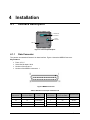
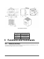
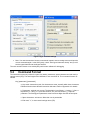
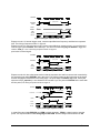
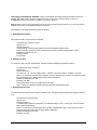
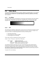
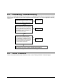
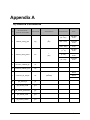
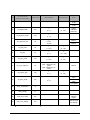
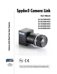
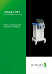
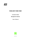
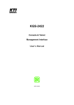
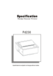
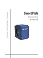
Camera Link Line Scan Cameras SwordFish User’s Manual SwordFish Camera User’s Manual SF-10-XXK40-02-R 1 Contents 1 INTRODUCTION ................................................................................................................................................ 3 1.1. 1.2. OVERVIEW ...................................................................................................................................................... 3 IMAGE SENSOR................................................................................................................................................ 3 2 PERFORMANCE SPECIFICATIONS.............................................................................................................. 4 3 PRECAUTION ..................................................................................................................................................... 5 4 INSTALLATION ................................................................................................................................................. 6 4.1 4.2 4.3 5 INTERFACE DESCRIPTION ................................................................................................................................ 6 INSTALLATION OVERVIEW .............................................................................................................................. 8 MECHANICAL INTERFACE ............................................................................................................................... 8 FUNCTIONS AND COMMANDS ..................................................................................................................... 9 5.1 5.2 5.3 5.4 5.5 5.6 5.7 5.8 5.9 6 SOFTWARE INTERFACE.................................................................................................................................... 9 COMMAND FORMAT ...................................................................................................................................... 10 EXPOSURE MODE .......................................................................................................................................... 11 VIDEO MODE ................................................................................................................................................ 14 DATA MODE ................................................................................................................................................. 16 OFFSET AND GAIN ......................................................................................................................................... 16 RETURNING VIDEO INFORMATION ................................................................................................................ 18 SETTING A REGION OF INTEREST ................................................................................................................... 19 QUERY COMMAND ........................................................................................................................................ 20 TROUBLESHOOTING..................................................................................................................................... 20 6.1 6.2 6.3 6.4 NO IMAGE ..................................................................................................................................................... 20 POOR QUALITY IMAGE .................................................................................................................................. 21 INTERFACING TROUBLESHOOTING ................................................................................................................ 23 OTHER PROBLEMS......................................................................................................................................... 23 APPENDIX A ............................................................................................................................................................. 24 A) CAMERA COMMANDS ....................................................................................................................................... 24 INDEX ......................................................................................................................................................................... 27 DOCUMENT REVISION HISTORY ...................................................................................................................... 28 2 SwordFish User’s Manua 1 Introduction 1.1. Overview The SwordFish series of line scan cameras, available in 1k to 2k resolutions, Cabling and interface are with the Camera Link Base standard. SwordFish is with features of high responsivity, enhanced blue response and wide dynamic range, and so on. This camera is especially suitable for industrial applications such as color sorting and web inspection. In addition to electronic shutter, programmable analog gain, offset and external trigger function, the camera incorporates flat-field correction function. Equipped with a variety of camera lens adapters, the camera can be connected with many standard lenses to meet the users’ needs. 1.2. Image Sensor This camera incorporates Teledyne DALSA’s image sensor IL-P3-B with 14 μm square pixels, 100% fill factor and resolutions of 1024 or 2048 active pixels. As shown in Figure 1, the IL-P3-B CCD operates with a single tap. Figure 1: IL-P3 Image Sensor Block Diagram The IL-P3-B CCD, with enhanced blue response, is a high responsivity sensor with a peak of 43 V/ (uJ/cm²). This sensor also has a high dynamic range up to 1820:1(65dB). These features make the CCD ideal for applications in color sorting and web inspection. SwordFish User’s Manual 3 Figure 2a IL-P3-B CCD spectral response Figure 2b IL-P3-B CCD responsivity 2 Performance Specifications Table 1 Performance Specifications Features Resolution Color/mono Pixel clock Speed Tap Pixel size line rate Dynamic range Bit depth Trigger 1024 pixels Note 2048 pixels Black and white 40MHz 40MHz 1 1 14 μm x 14 μm 14 μm x 14 μm 1 kHz -36 kHz 1 kHz -18 kHz 60 dB 60 dB Programmable, 8 bit / 10 bit / 12 bit External or internal Mechanical interface/Electrical interface 4 Power < 6.0 W @ 12 VDC (±20%) Interface Camera Link™ (Base) Data Connector MDR26 (female) Installation Accuracy of CCD <0.1mm Lens Mount M42×1(Spiral Shape),(conformity F,PK or MD ), mount C not used in 2k pixels Housing Size (L x W x H) 66 mm x 74 mm x 55 mm SwordFish User’s Manua ≤500 g (without adapters) Weight Storage Temperature Operation Temperature -20 to 60 °C 10 to 50 °C Shock 15 g, half sine, 11 ms Vibration Random vibration in three directions: x,y,z. 4.88m/s2 , 0-1500 Hz Function Analog Gain Range Analog Offset -12 dB to +20 dB 0 to 255 DN Programmable integration time, line rate Programmable bit depth, test pattern, and diagnostics Supporting FFC(Flat-field correction) 3 Precaution Read this manual carefully before using the camera. Confirm that the camera’s packaging is undamaged before opening it. If the packaging is damaged please contact the related logistics personnel. Do not open the housing of the camera. The warranty becomes void if the housing is opened. Keeps the camera housing temperature in the range of 10 to 50 °C during operation. Otherwise the red alarm light will turn on and the alarm instructions will be fed back to the host computer. If this happens, the camera will not turn off automatically, users should set by themselves. Be sure not to operate the camera in the vicinity of strong electromagnetic fields. Avoid electrostatic charging, violent vibration, and excess moisture. Customers can choose different lens options. We provide variety of lens adapters to meet the ideal performance specifications. To clean the CCD, avoid electrostatic charging by using a dry, clean absorbent cotton cloth dampened with a small quantity of pure alcohol. Do not use methylated alcohol. To clean the surface of the camera housing, use a soft, dry cloth. To remove severe stains, use a soft cloth dampened with a small quantity of neutral detergent, then wipe dry. Do not use volatile solvents such as benzene and thinners; they can damage the surface finish. No support hot plugging, please make sure disconnect the power of camera before you do it. SwordFish User’s Manual 5 4 Installation 4.1 Interface Description CameraLink Connector Power Connector LED Figure 3. Camera Inputs/Outputs 4.1.1 Data Connector The camera uses standard Camera Link base interface. Figure 4 shows the MDR26 Connector. Key Features: Ports: A, B, C Serial data bit depth: 28 bit Number of the sensors: 1 Number of the MDR26 connectors: 1 Figure 4 MDR26 Connector Table 2 Definition of each pin of Camera Link Camera Connector 6 Right Angle Frame Grabber Camera Link Camera connector Right Angle Frame Grabber Camera Link 1 1 inner shield 19 8 X3+ 14 14 inner shield 7 20 SerTC+ 2 25 X0- 20 7 SerTC- 15 12 X0+ 8 19 SerTFG- SwordFish User’s Manua 3 24 X1- 21 6 SerTFG+ 16 11 X1+ 9 18 Exsync- 4 23 X2- 22 5 Exsync+ 17 10 X2+ 10 17 PRIN+ 5 22 Xclk- 23 4 PRIN - 18 9 Xclk+ 11 16 CC3- 6 21 X3- 24 3 CC3+ a.The 28 bit imaging data, including video and control signal such as LVAL, FVAL, and DVAL, are transmitted through the four pairs of signal wires: (X0-, X0+), (X1-, X1+), (X2-, X2+) and (X3-, X3+). For the line scan cameras the control signal is LVAL and the other two are invalid. LVAL is defined HIGH for valid pixels. b. (Xclk- , Xclk+), namely STROBE, the inputs for pixel clock, operates at a pixel clock rate of 40MHz. This camera’s data should be sampled on the rising edge of STROBE. c. (SerTC+, SerTC-) and (SerTFG-, SerTFG+), Serial Communication Interfaces, are used for the camera to communicate with the host computer. d. (Exsync-, Exsync+; PRIN+, PRIN –) and (Exsync-, Exsync+; PRIN+, PRIN –) are two pairs of inputs for the external trigger signal of exposure mode. This camera uses the edge of Exsync to trigger line readout and PRIN for pixel reset. The characteristics of the two signals and their applications are specified in section 5.3. e. (CC3+, CC3-) and (CC4-, CC4+) are invalid. 4.1.2 Power Connector Table 3 shows the pins and the descriptions of the power connector (Hirose 6-pin). The P/N is HR10A-7R6PB. Table 3 power connector (Hirose 6-pin) Pin 1 2 3 4 5 6 Description +12 V +12 V +12 V GND GND GND Note The three pins are internal connected. The three pins are internal connected. The camera requires a single voltage input. The recommended voltage is +12 V (± 20%). The camera meets all performance specifications using standard switching power supplies. Well regulated linear supplies, which Teledyne DALSA recommends, provide optimum performance. When setting up the camera’s power supplies follow these guidelines: Protect the camera with a fast-blow fuse between the power supply and camera. Do not use the shield on a multi-conductor cable for ground. SwordFish User’s Manual 7 4.1.3 Check the order of power and ground, the camera will be damaged if the order is converse. Keep leads as short as possible to reduce voltage drop. LED Status Indicator The camera is equipped with a red/green LED used to display the operational status of the camera. The following table summarizes the operating states of the camera and the corresponding LED states. Table 4 States of the camera and the corresponding LED LED state Priority Camera Status Steady RED 1 Warning Blinking GREEN 2 Progress Steady GREEN 3 OK Condition Current camera temperature exceeds specific limit Lengthy operation in progress Blinking Period 200 ms Healthy Note: When more than one status happen at a time, the LED shows the status of the highest priority. There are corresponding information of error and warning status to describe the current states of a camera. 4.2 Installation Overview Connect Camera Link™ cables from camera to standard Camera link frame grabber. As an alternate, you can apply the camera link cable assembly manufactured by 3M. The maximum allowed length for the MDR cable used with the SwordFish camera is 10 meters. Connect power cables from camera to the voltage source. For proper EMI protection, the power supply cable attached to this plug must be a twin-cored, shielded cable. Also, the housing of the Hirose plug must be connected to the cable shield and the cable must be connected to earth ground at the power supply. 4.3 Mechanical Interface The SwordFish camera applies a M42 × 1 mount. It can be connected to varied standard lenses with different adapters, such as the C-Mount, F-Mount, PK-Mount, and so on. Users can choose a lens appropriate for their applications. Table 5 lists the lens mounts and their back focal distance. 8 SwordFish User’s Manua Figure 5 Mechanical Interface Table 5 The lens mount and the back focal distance Mount Back Focal Distance (sensor die to adapter) C-Mount 17.52 ±0.25 mm F-Mount 46.5 ±0.25 mm PK-Mount 45.5 ±0.25 mm 5 Functions and Commands 5.1 Software Interface The camera transfers information to and from the host through the RS-232C communication port. To set commands at the HyperTerminal, refer to the following: SwordFish User’s Manual 9 Figure 6 HyperTerminal settings Note: You cannot amend the incorrect commands. Instead, enter a carriage return and input the correct commands again. In the ASCII setup, check “Echo typed characters locally” and you will see the typed characters at the HyperTerminal. The user can also choose to use a third-party serial control software for debugging. 5.2 Command Format The instructions commonly include four parts: key words, parameters, space character and end mark (a carriage return (CR)). The total length of the characters is not more than 32. The command format is as follows: Key [parameter1] [parameter2] a. Key words: Instruction words, four characters at most, normally within three characters. Different functions have different instruction characters. Refer to Appendix A for details. b. Parameters: optional, two at most. The description is as follows: i = integer, f = float, t = tap selector, s = string, x1 = pixel start number, x2= pixel end number, [] = optional parameter. The floating-point parameters must have three digits after the decimal point. c. Space characters: at least one. More than one is permissible. d. End mark,” \r”, is also named carriage return (CR). 10 SwordFish User’s Manua 5.3 Exposure Mode The camera’s line rate (synchronization) is generated internally or input from a frame grabber/host system. With six different exposure modes setting by the command sem i, the camera delivers many possibilities for flexible camera timing. When the camera is powered on for the first time, it defaults (no external input required) to exposure mode 2. Table 6 outlines each of these six exposure modes. Table 6 Exposure Modes Mode SYNC PRIN Programmable line rate Programmable exposure time 1 Internal Internal No No 2 Internal Internal Yes Yes 3 4 External External Internal Internal No No No No 5 External External No No 6 External Internal No Yes Description Maximum line rate and exposure time Programmable line rate and exposure time Maximum exposure time Smart EXSYNC External line rate and external pixel reset Fixed integration time Some exposure modes have some similarities in timing, Refer to Figures 7 to 10 for timing details of the six different exposure modes. The values set by user can be saved by the command ‘wus’ under programmable modes. STROBE T_line period EXSYNC/ SYNC PIXEL RESET SYNC_h T_exposure PIXEL Transfer clock T_read out LINE VALID DATA Figure 7 Timing for exposure mode 2 and exposure mode 6 Exposure mode 2 is internal trigger mode, used set command to set T_exposure, range is from 1.750us to T_line period, internal trigger signal is SYNC, used ssf command to set line frequency =1/ T_line period, T_line 6 6 period range is from 54054ns to 1.61*10 ns in 2k pixels, or from 27777ns to 1.61*10 ns in 1k pixels. The timing of exposure mode 2 in figure 7. Exposure mode 6 is external trigger mode, used set command to set T_exposure, range is from 1.750us to T_line period, external trigger signal is EXSYNC, that is CC1 input. The camera uses the rising edge of EXSYNC to trigger line readout , SYNC_h > 75ns. The timing of exposure mode 6 in figure 7. pixel reset and pixel transfer clock are internal signal. SwordFish User’s Manual 11 STROBE T_line period EXSYNC/ SYNC SYNC_h PIXEL RESET T_read out LINE VALID DATA Figure 8 Timing for exposure mode 1 and 3 Exposure mode 1 is internal trigger mode, camera output Maximum frequency and Maximum exposure time. The timing of exposure mode 1 in figure 8. Exposure mode 3 is external trigger mode, camera output Maximum exposure time in current frequency, external trigger signal is EXSYNC, that is CC1 input. The camera uses the rising edge of EXSYNC to trigger line readout , SYNC_h > 75ns. The timing of exposure mode 3 in figure 8. pixel reset is internal signal. STROBE T_line period EXSYNC T_exposure T_read out LINE VALID DATA Figure 9 Timing for exposure mode 4 Exposure mode 4 is also called smart mode in that the exposure time and line rate are both controlled by the external trigger signal EXSYNC, that is CC1 input. The exposure starts on the rising edge of the signal and the charges are transferred on the falling edge. The pulse width of EXSYNC high level, namely the exposure time(T_exposure), is not allowed to be less than 2 µs. The period of EXSYNC is the same with the line period, The timing of exposure mode 4 in figure 9. STROBE T_line period EXSYNC >150ns T_exposure PRIN >150ns T_read out LINE VALID DATA Figure 10 Timing for exposure mode 5 In mode 5,the two signals EXSYNC and PRIN are both necessary, PRIN is a signal used to reset the pixels. The exposure starts on the rising edge of the PRIN and the charges are transferred on the 12 SwordFish User’s Manua falling edge of the EXSYNC. EXSYNC is the line rate signal, the frequencies are the same for the two signals. The width of the low pulse is larger than 150 ns. The timing of exposure mode 5 in figure 10. T_read out is 51200ns in 2k pixels, or 25600ns in 1k pixels in all figure. Note:EXSYNC should not be clocked faster than the camera’s specified maximum line rate. The camera ignores the EXSYNC pulse until it has completed reading the last line out. More details for the related instructions are as follows: a. Setting Exposure Mode Set exposure mode, using the sem command: Command: set_exposure_mode Syntax: sem i Syntax Elements: i Factory setting is mode 2 with 5kHz line rate and maximum exposure time. Notes: To obtain the current value of the exposure mode, use the command sem or gcp. Related Commands: ssf, set Example: sem 2 Prompt: OK> b. Setting Line Rate To set the line rate, use the command ssf. Camera must be operating in exposure mode 2. Command: set_sync_frequency Syntax: ssf i Syntax Elements: i Line rate unit : Hz , line rate range: 620Hz~18639Hz in 2k pixels or 620Hz~36000Hz in 1k pixels. Notes: To read the current line rate frequency, use the command ssf or gcp. If you input an invalid line rate frequency, the valid range of values will be displayed. Related Commands: sem, set Example: ssf 3000 Prompt: Exposure Time Set To Max Of xxx.xxx uSec ! Note:There is no deviation between the Set value and the Effective value. c. Setting Exposure Time To set the camera exposure time, use the command ‘set’. Camera must be operating in exposure mode 2 or 6. Command:set_exposure_time Syntax: set f Syntax Elements: f f - Floating point number in unit μsecs. For allowable range 1.750 ~ 1612.9 [µs], see the camera help screen (h command). Notes: To read the current exposure time, use the command set or gcp. If you enter an invalid exposure time, the valid range of values will be displayed. Related Commands: sem, ssf Example: set 100 SwordFish User’s Manual 13 Prompt: OK> 5.4 Video Mode The video mode sets whether the camera is running in calibrated or uncalibrated mode, or if it is running in test mode. For the uncalibrated mode, the image data is read out without any calibration. In calibrated mode, images are output after FFC. Test mode is especially useful for service purposes and for camera failure diagnostics. 5.4.1 Test Mode To set the test mode, use the command svm 2. The test image is formed with gray value (scale gradient) that ranges from 0 DN (stepping up) to 2047 DN (in 12 bit Data mode). Test mode is used for failure diagnostics of the connection from the camera to the grabber card. Figure 11 shows the test result. Figure 11 test image 5.4.2 FFC This camera has the capability to calibrate itself in order to remove non-uniformity in the image. This video correction operates on a pixel-by-pixel basis and implements a two point correction for each pixel. This correction can reduce or eliminate image distortion caused by the following factors: Fixed Pattern Noise (FPN) Photo Response Non Uniformity (PRNU) Lens and light source non-uniformity The two point correction is implemented such that for each pixel: Voutput = (Vinput - FPN( pixel ) - digital offset) * PRNU(pixel) Where Voutput = digital output pixel value Vinput = digital input pixel value from the CCD PRNU( pixel) = PRNU correction coefficient for this pixel FPN( pixel ) = FPN correction coefficient for this pixel The calibration algorithm is performed in two steps. The fixed offset (FPN) and the digital offset are determined first by performing a calibration without any light. This calibration determines exactly how much offset to subtract per pixel in order to obtain flat output when the CCD is not exposed. The white light calibration is performed next to determine PRNU correction coefficient required to bring each pixel to the required value (balance target) for flat, white output. To perform FFC, do the following: 14 SwordFish User’s Manua 1. Send the following commands through serial interface svm 1 //Set the calibrate mode. 2. Set the operating parameters (such as line rate, exposure time, analog offset, analog gain, for example). 3. Set line sample number, using command css (the default is 64 lines). 4. Operate the camera in darkness, covering the lens with a lens cap. Verify the output signal level is within the valid range of 0 to 511 DN for 10 bit data mode, using command gl or gla. If the signal level is too low, adjust the analog offset (sao). If the signal level is too high, ensure that no light is entering the camera; reduce the analog offset or the gain level (sg). 5. Perform dark calibration, using command ccf. If the calibration is accomplished, the camera returns OK>. Otherwise the camera returns an error message. Dark calibration automatically calibrates FPN coefficients and digital offset. 6. After the calibration is complete, you can save these settings and the PRNU coefficients so they will be remembered after power-down. To do so, issue the command wus and wpc. 7. Place a clean white uniform reference in front of the camera. White paper is often not sufficient because the grain in the white paper will distort the correction. White plastic or white ceramic will lead to better balancing. 8. Make sure that the camera is in exposure status, with the lens cap off and white reference as imaging object. Verify the output signal level is within the valid range of 512 to 1007 DN for10 bit data mode, issuing the command gl or gla. If the signal level is too low or too high, adjust the analog gain level, using command sg. 9. Instruct the camera to perform a white light calibration by using the command ccp. The camera will return with OK> if no error occurs. 10. After the calibration is complete, you can use the wus command to save these settings. To save PRNU and FPN coefficients, issue the command wpc. Otherwise, the current settings will be lost after power-down. The related commands are as follows: a. Setting the Video Mode Using command svm i, the Video Mode Sets whether the camera is running in calibrated, uncalibrated mode or test mode. Command: set_video_mode Syntax: svm i Syntax Elements: i Allowable value the Video Mode: 0: uncalibrated mode, invalid video correct 1: calibrated mode, valid video correct 2: test patten right Notes: To set the current video mode, use the command svm or gcp. Example svm 1 Prompt: OK> b. Set the FPN coefficient Command: set_FPN_coefficient Syntax: sfc i i Syntax Elements: i : the pixel number from 1 to 2048 in 2k pixels or from 1 to 1024 in 1k pixels. SwordFish User’s Manual 15 i : Coefficient value in a range from 0 to 127. Example: sfc 10 50 c. Read the FPN coefficient Syntax: gfc i Syntax Elements: i: the pixel number to read. Example: gfc 10: continually show 16 FPN coefficients from the beginning of pixel 10. d. Set the PRNU coefficient Syntax: spc i i Syntax Elements: pixels. i: the pixel number from 1 to 2048 in 2k pixels or from 1 to 1024 in 1k I: Coefficient value in a range from 0 to 511. Example: spc 10 50 e. Read the PRNU coefficient Syntax: gpc i Syntax Elements: I; the pixel number to read. Example: gpc 10: Continually show 16 FPN coefficients from the beginning of pixel 10. 5.5 Data Mode The camera provides three valid output data modes: 8 bit, 10 bit and 12 bit. To select the data mode, use the command sdm. a. Setting the Data Mode Command: set_data_mode Syntax: sdm i Syntax Elements: i 0 8-bit, 1 10-bit, 2 12-bit Notes: To obtain the current data mode, use the command sdm or gcp. Example: sdm 2 Prompt: OK> 5.6 Offset and Gain a. set_analog_offset Command: set_analog_offset Syntax: sao t i Syntax Elements: t; Tap selection. Allowable values are 1 for one tap or 0 for all taps. Since this is a one tap camera, the values 1 or 0 are interchangeable. i Analog offset value. Allowable range is 0 to 1023. 16 SwordFish User’s Manua Notes: The image gray value will grow when increasing the value of i. The increasing amount of gray value is close to 1/4 of the setting value . For example, a setting value of 100 will result in an gray value offset of about 25 DN. The command can be used in uncalibrated mode and test mode. Example: sao 0 200 Prompt: OK> b. Subtracting Offset in Calibrated Mode You can subtract the A/D offset from the video signal prior to PRNU correction, available only in calibrated mode. In other modes the cameras will return an error. Command: set_digital_offset Syntax: sdo t i Syntax Elements: t Tap selection. Allowable values are 1 for one tap or 0 for all taps. Since this camera is a one tap camera, the values 1 or 0 are interchangeable. i Subtracted offset value in a range from 0 to 511. Notes: The offset digital value is subtracted from the digital video signal, so it is not allowed to exceed the signal value. Example: sdo 0 100 c. Calibrating Offset Set the average output level to a specific value, adjusting the analog offset value. Command: calibrating_analog_offset Syntax: cao t i Syntax Elements: t Tap selection. Allowable values are 1 for one tap or 0 for all taps. Since this camera is a one tap camera, the values 1 or 0 are interchangeable. i The line average in a range dependent on the current camera data mode setting. 8 bit: 1 to 14DN; 10 bit: 4 to 62DN; 12 bit: 16 to 249DN. Notes: The command is valid in uncalibrated mode. The second parameter presents the average signal value. It can be set different in varied modes as shown above. Example: cao 0 100 d. set_analog_gain Command: set_analog_gain Syntax: sg t f Syntax Elements: t Tap selection. Allowable values are 1 for one tap or 0 for all taps. Since this camera is a one tap camera, the values 1 or 0 are interchangeable. f Gain setting. Range: -12 - +20dB (Here the gain means the gain of the analog image signal). . Example: sg 0 -12 SwordFish User’s Manual 17 e. set_digital_gain Command: set_digital_gain Syntax: ssg t i Syntax Elements: t Tap selection. Allowable values are 1 for one tap or 0 for all taps. Since this camera is a one tap camera, the values 1 or 0 are interchangeable. i Gain setting. The gain range is from 0to 511(equal to a gain from 1 to 1.999). Gain (multiple) = (Gain (DN) + 512) / 512. Example: ssg 1 15 f. Calibrating analog Gains Set the average output level to a specific value, adjusting the analog gain. This function requires a constant light input while it executes. This feature is beneficial for achieving a common output level for multiple cameras in a system. Command: calibrating_analog_gain Syntax: cag t i Syntax Elements: t Tap selection. Allowable values are 1 for one tap or 0 for all taps. Since the camera is a one tap camera, the values 1 or 0 are interchangeable. i Line average in a range dependent on the current camera data mode setting: 8 bit: 64 to 251 DN; 10 bit: 256 to 1007 DN; 12 bit: 1024 to 4031 DN; Notes: This function, valid in uncalibrated mode, requires a constant light input while it executes. The allowable range of the output value is dependent on the current data mode, as shown above. Related Commands: gla, gl Example: cag 1 156 5.7 Returning Video Information The camera’s microcontroller has the ability to read video data. This functionality can be used to verify camera operation and to perform basic testing without having to connect the camera to a frame grabber. This information is also used for collecting line statistics for calibrating the camera. a. Returning a Single Line of Video Command: Get_line Syntax: gl [x1] [x2] Syntax Elements: [x1] Optional parameter. This sets the start pixel to display on screen. Allowable range is from 1 to 2048 in 2k pixels or from 1 to 1024 in 1k pixels. This parameter does not affect the Min, Max, and Mean statistics generated at the end of the line output. [x2] Optional parameter. This sets the end pixel to display on screen. Allowable range is (x1 + 1) to sensor pixel count 2048 in 2k pixels or pixel count 1024 in 1k pixels. This parameter does not affect the Min, Max, and Mean statistics generated at the end of the line output. Notes: If you do not specify a pixel range to display, the line output will display all sensor pixels on screen. The Min, Max, and the statistic region of Mean of the end of the line are the region of interest (roi). 18 SwordFish User’s Manua Values returned are in DN. Example: gl 10 20 b. set the number of lines to sample Syntax: css i Syntax Elements: i Number of lines to sample. Allowable values are 16, 32, or 64 (factory setting). Notes: To return the current setting, use the command css and gcp. Example: css 32 c. Returning Multiple Lines of Video Syntax: gla [x1] [x2] Syntax Elements: [x1] Optional parameter. This sets the start pixel to display on screen. Allowable range is from 1 to 2048 in 2k pixels or from 1 to 1024 in 1k pixels.. This value does not affect the Min, Max, and Mean statistics generated at the end of the line output. [x2] Optional parameter. This sets the end pixel to display on screen. Allowable range is (x1 + 1) to sensor pixel count 2048 in 2k pixels or pixel count 1024 in 1k pixels. This value does not affect the Min, Max, and Mean statistics generated at the end of the line output. Notes: When this function executes, the sample lines, set by the css command, and collected and averaged. If you do not specify a pixel range to display, the line output will display all sensor pixels on the screen. If a region of interest has been set using the roi command, the Min, Max, and Mean statistics at the end of the line output include statistics for the region of interest only. Values returned are in DN. Example: gl 10 20 5.8 Setting a Region of Interest The command roi sets the pixel range used to collect the end of line statistic and sets the region of pixels used in the cag, cao, gl, gla, ccf, and ccp commands. To define a region of interest, use the roi command. Command: region_of_interest Syntax: roi x1 x2 Syntax Elements: x1 : Pixel start number in a range from 1 to sensor pixel count 2048 in 2k pixels or pixel count 1024 in 1k pixels. It must be less than the pixel end number. x2 :Pixel end number in a range from (x1 + 1) to sensor pixel count 2048 in 2k pixels or pixel count 1024 in 1k pixels. It must be greater than the pixel start number. Related Commands: gl, gla Example: roi 10 50 Prompt: OK> SwordFish User’s Manual 19 5.9 Query Command a. Read the camera ID, using command gci. Command: get_camera_id Syntax: gci Prompt: Camera Network ID: 0 b. Read the camera serial number, using command gcs. Command: get_camera_serial Syntax: gcs Prompt: Camera Serial No.: xxxxxxxx c. Read the firmware version, using command gcv. Command: get_camera_version Syntax: gcv Prompt: Firmware Design Rev.: SF2KFMBxxx FPGA Design Rev.: SF2KFFBxxx d. Display the online help, using command h. Command: help Syntax: h Prompt: Command: …… Command: …… 6 Troubleshooting 6.1 No Image Follow the steps in chart 6.1 to diagnose your camera if you see no image at all with camera power and the LED indicator on. 20 SwordFish User’s Manua Reseat all the cable connections in the system including power source, camera and PC. Is the problem still present? No Exit this chart. Yes Consult the Camera Expert and check the pixel values in each captured line and the individual values of each pixel. Is there at least one value? No Go to the interface Troubleshooting chart. Yes Activate the factory set, namely rfs. Then check the image. Is the problem still present? No Some of the camera’s settings were significantly misadjusted. Review the camera manual to make sure that you are setting the camera correctly. Yes Contact Teledyne DALSA technical support. The contact numbers, Website and email address appear on the first page of this manual. Figure 12 Troubleshooting chart with no image output 6.2 Poor Quality Image If the image is in poor quality, check whether the lens is clean. Then you can follow chart 6.2 to solve the problem. SwordFish User’s Manual 21 Make sure that all the hardware is connected correctly. Set the camera to test mode, using command svm 2. Check the image carefully using Camera Expert on the host computer. Is it the same with the test image described in section 5.4? No Go to the interface troubleshooting chart. Yes No Activate the factory set, namely rfs. Then check the image. Is the problem still present? Some of the camera’s settings were significantly misadjusted. Review the camera manual to make sure that you are setting the camera correctly. Yes Images are too bright or too dark? Other image problems? Image looks noisy? Yes Yes Yes Try the following: 1. Remove the lens. 2. Check the lens aperture. If the images are too dark, try opening the aperture. Close the aperture if the images are too bright. 3. Check the exposure time. If the images are too dark, try increasing the exposure. If they are too bright, decrease the exposure. 4. Check your gain setting. If the images are too dark, try increasing the gain. Decrease the gain if they are too bright. Has the problem been corrected? Yes No The following steps reduce noise: 1. Make sure that you are using a DC light source. Using an AC light source can produce noise. 2. Make sure that the working environment has no strong electromagnetic interference. 3. Make sure that the camera operates without violent vibration. 4. Make sure that the camera has proper ventilation. Avoid the camera becoming too hot. 5. Check the exposure time. If you use an extremely long exposure time, the image can become noisy. 6. Check the gain setting. Using a very lo w or a very high gain setting can cause noise. 7. Examine the objects that you are imaging. Objects with characteristics such as changing surface texture or reflectance will produce images that appear noisy. Has the problem been corrected? Exit the chart. Yes No Exit the chart. Contact TELEDYNE DALSA technical support. Refer to the first page of this manual for the contact numbers, website and email address Figure 13 poor image quality trouble shooting chart 22 SwordFish User’s Manua 6.3 Interfacing Troubleshooting If you see no image signal with the camera power-on, it is Mostly because that your camera does not have all the correct connections or part of the components cannot work well. Try to solve the problems referring to chart 6.3. Reseat all the cable connections in the system including power source, camera and PC. Is the problem still present? No Exit this chart. Yes Use a multimeter to check the power source for the camera. The output must be in the allowable range. Make sure that the power source meets the other specifications shown in section 4.3.2. Is the power source OK? No Replace the power source. Yes If there are no problems with the connections, try to locate the problem by substitution. (Substitute only one piece of hardware at a time and retry the system after each substitution.) Is the problem still present? No Exit this chart. Yes Contact Teledyne DALSA technical support. Refer to the last page of this manual for the contact numbers, website and email address. Figure 14 interface troubleshooting chart 6.4 Other Problems In case of any other problems that cannot be solved, contact Teledyne DALSA Technical Support. SwordFish User’s Manual 23 Appendix A a) Camera Commands SN 1 2 PC commands (control commands) calibrate_analog_gain calibrate_analog_offset Commands cag cao 3 correction_calibrate_fpn ccf 4 correction_calibrate_prnu ccp Parameters1 t (0/1) t (0/1) Parameters2 Note i (64 - 251) 8 bit data mode (256 - 1007) 10 bit data mode (1024 - 4031) 12 bit data mode i ( 1 - 14) 8 bit data mode (4 - 62) 10 bit data mode (16 - 249) 12 bit data mode 16lines 5 correction_set_sample css i (16/32/64) 32lines 64lines 24 8 get_camera_id gci 9 get_camera_model gcm 10 get_camera_parameters gcp 11 get_camera_serial gcs 12 get_camera_version gcv SwordFish User’s Manua SN PC commands (control commands) Commands Parameters1 Parameters2 Note Continually show 16 parameters from the beginning of pixel i. 13 get_fpn_coeff gfc i 1 (1 – PN ) 14 get_line gl i 1 (1 - PN ) i 1 (1 - PN ) Specify the display range. 15 get_line_average gla i 1 (1 – PN ) i 1 (1 – PN ) Specify the display range. 16 get_prnu_coeff gpc 17 get_sensor_serial gss 18 help h 19 region _of_interest roi 20 reset_camera rc 21 reset_pixel_coeffs rpc 22 restore_factory_settings rfs 23 restore_user_settings rus 24 set_analog_offset 25 Continually show 16 parameters from the beginning of pixel i. i 1 (1 - PN ) i 1 (1 - PN ) i 1 (1 - PN ) sao t (0/1) i (0 - 1023) set_baud_rate sbr i (9600/19200/57600/115200) 26 set_camera_id sci s (A-Z/0-9) 27 set_data_mode sdm i SwordFish User’s Manual 9600/19200 /57600/115200 8 bit 25 SN PC commands (control commands) Commands Parameters1 Parameters2 (0 - 2) Note 10 bit 12 bit 28 set_digital_offset sdo t (0 - 1) set_exposure_mode sem i (1 - 6) set_exposure_time set f (1.7501612.9) 29 i (0 - 511) Mode 2 Mode 6 30 set_fpn_coeff sfc i 1 (1 - PN ) i (0 - 127) 31 set_gain sg t (0 - 1) f (-12 - +20) 32 set_prnu_coeff spc i 1 (1 - PN ) i (0 - 511) 33 set_sync_frequency ssf i (620 - 18639 Hz) in 2k pixels (620 - 36000 Hz) in 1k pixels 34 set_system_gain ssg t (0 - 1) 35 set_video_mode svm 36 verify _temperature vt 37 verify_voltage vv 38 write_pixel_coeffs wpc 39 write_user_settings wus Valid in calibrated mode only. Mode 2 i (0 - 511) i (0 - 2) 0 :Uncalibrated video 1: Calibrated video 2: Test pattern Write current FPN and PRNU Coefficients Write all of the user settings NOTES:1. PN is 1024 in 1k pixels number,or 2048 in 2k pixels number. 26 SwordFish User’s Manua Index A Analog offset, 17 analog_gain, 18 applications, 3, 7, 8 C calibrating the camera, 18 Camera Link, 3, 4, 6, 8 clean the CCD, 5 commands, 9, 10, 15, 19, 24 D diagnose, 20 E H help, 20 L LED states, 8 lens mounts, 8 P power connector, 7 PRNU, 14, 15, 16, 17, 26 S Setting Exposure Mode, 13 Setting Exposure Time, 13 Setting Line Rate, 13 exposure modes, 11 F FFC, 14 Format, 10 FPN, 14, 15, 16, 26 SwordFish User’s Manual T Test Mode, 14 the region of interest, 19 27 Document Revision History Version Data Description of Revisions 00 2009-09-09 Initial release 01 2011-01-04 Modify some inaccurate description Improve the resolution of the mechanical drawing 02 28 2014-07-10 1. Change the range of parameters under the command “sao” and “cao” . 2. Eliminate the deviation between the set value and effective value when using command “ssf” in exposure mode 2 3. Upgrade the Firmware version and FPGA version. 4. Change the camera model From”SF-10-02K40-01-R” to ” SF-10-02K40-02-R” SwordFish User’s Manua