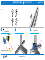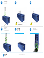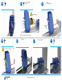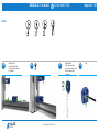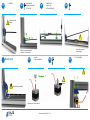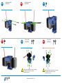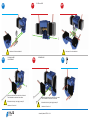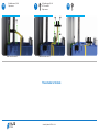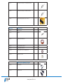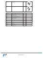
1
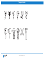
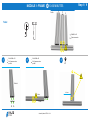
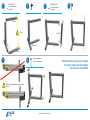
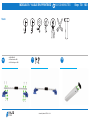
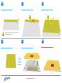
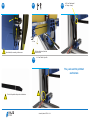
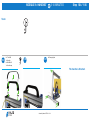
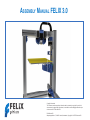
ASSEMBLY MANUAL FELIX 3.0 Copyright Information this document contains proprietary information that is protected by copyright. no part of this document may be photocopied, reproduced, or translated to another language without the prior written consent of FELIXrobotics BV. FelixRobotics BV Wapendragervlinder 17, 3544DL utrecht, netherlands, Copyright © 2013 FELIXrobotics BV Introduction Dear Customer, First of all thank you for choosing FELIXprinters! We advise you to follow this manual as carefully, to get your FELIXprinter up and running as fast as possible. When things are unclear or if you have any remarks, please don’t hesitate to contact us at [email protected]. It is better to ask/read twice than to wait a week for new parts. Another great source of knowledge and information is our user Forum. It is a nice place to share information and experiences. So we definately recommend to get a forum account at www.felixprinters.com/forum Before starting to build the kit it is recommended to check if all parts are present by comparing it witht he bill of materials at the appendix of this document. Have fun building! Kind regards, Felixprinters team. Assembly Manual FELIX 3.0 V1 Index: Description:Step:Page: Required tools5 Frame1 / 96 Z-axle10 / 328 X-axle33 / 5013 Extruder51 / 7216 Y-axle and printbed73 / 10323 Handle104 / 10629 Electronicabox107 / 11430 Wiring115 / 12732 Bom (Bill of Materials)38 Assembly Manual FELIX 3.0 V1 Required tools: Assembly Manual FELIX 3.0 V1 Module 1: FraMe Step 1 / 9 10-30 MInutEs Profile: 4 2 3 tools: Bolt M8 x 20 Frameconnector 1 ! Holes 1 2x Bolt M8 x 20 2x Frameconnector profile 4 2 2x Bolt M8 x 20 2x Frameconnector profile 1 3 ! Profile 4 ! holes Profile 1 Assembly Manual FELIX 3.0 V1 160 mm 2x Bolt M8 x 20 2x Frameconnector 2x profile 2 4 5 6 2x Bolt M8 x 20 2x Frameconnector 1x profile 3 7 Profile 2 ! Holes Profile 3 160 mm Profile 2 8 9 ! 4x End cap square 1x End cap rectangle Make sure everything is perpendicular and aligned. Assembly Manual FELIX 3.0 V1 When all beams are properly aligned, it’s time to fasten the bolts tightly. The frame is now finished. Module 2: Z-axle 45-90 MInutEs Step 10 / 32 tools: Example mounting T-slots: 10 4x CsK bolt M3x8 1x Motor 1x Z-axle motor bracket 11 2x M4 t-slot Cable oriëntation ! Label end of the wire with the letter: Z Assembly Manual FELIX 3.0 V1 12 2x Bolt M4x20 2x small washer M4 13 ! Make sure the plastic is good connect it to the frame! Don’t let the cart run off the rail!! 14 3x M4 t-slot 1x Z-axle rail 3x Bolt M4x20 15 16 ! 10mm between rail and plastic! 10mm 12mm ! 12mm from side rail to side frame! Assembly Manual FELIX 3.0 V1 1x Z-axle carriër 1x Copper nut for spindel 17 2x Bolt M4x40 2x Locknut M4 18 19 ! 20 2x Bolt M4x25 4x Bearing 4x small washer M4 21 ! Pull the Lochnuts in the plastic solid by tightening the bolts 22 7 Assembly Manual FELIX 3.0 V1 Remove the bolts M4x40 4x Bolt M5x16 4x small washer M5 23 24 4x CsK bolt M3x8 1x Motor 25 ! 1x pulley 1x set screw M3x4 Wire orientation! Label end of the wire with the letter: Y 26 27 ! 1x spindle 28 Distance pulley to motorface = 1-2mm Assembly Manual FELIX 3.0 V1 1x set screw M3x4 29 30 1x Bolt M4x20 1x small nut M4 31 1x Bolt M4x20 1x small washer M4 1x M4 t-slot The Z-axle is finished. Assembly Manual FELIX 3.0 V1 32 Module 3: x-axle Step 33 / 50 30-60 MInutEs tools: 33 1x Bolt M4x16 1x small washer M4 1x X-axle motor bracket 1x t-slot M4 34 35 Assembly Manual FELIX 3.0 V1 1x Bolt M4x40 5x small washer M4 1x X-axle belt mount part 2x Large washer M4 1x Bearing 36 Belt 37 1x t-slot M4 ! 38 1x Bolt M4x16 1x small washer M4 1x t-slot M4 39 2x Bolt M3x12 1x Hiwin rail 2x t-slot M3 (black) 40 tighten the bolt loosely ! 14 mm 14mm from side rail to side frame! Make sure the plasticgood connect it to the frame! Detail of 40 41 1x pulley 1x set screw M3x4 43 42 4x CsK bolt M3x8 ! ! ! 0,5mm Rail tight against plastic! Label the end of the cable: X Assembly Manual FELIX 3.0 V1 45 44 1x Extruder base 4x CsK M3x6 46 47 ! 48 1x Belt bracket 1x thin nut M4 1x Bolt M4x25 now attach the belt as shown! 50 49 +/- 1cm ! tension the belt. Make sure you have room to give more tension. ! Belt should be taut, but sled must run free. Assembly Manual FELIX 3.0 V1 the x-axle is finished. Module 4: extruder 30-90 MInutEs red = oPtIonal dual extruder tools: 51 1x Bolt M4x12 5x Large washer M4 4x Chrinkled washer 1x thin nut M4 52 1x Extruder wheel 1x set-screw M3x4 53 ! Large washer M4 2,5mm Chrinkeld washer Label end of the wire: Ext 0 2x For dual-head 2x For dual-head Label end of the 2e motorwire: Ext 1 Assembly Manual FELIX 3.0 V1 2x For dual-head Step 51 / 72 54 56 3x Bolt M3x16 1x Bearing 54a 55 57 1x thin nut M4 57a 3x Bolt M3x16 1x Bearing Assembly Manual FELIX 3.0 V1 55a 57b 1x thin nut M4 58 59a 2x Selflocking nut M4 2x Bolt M4x25 58a 60 ! 2x Selflocking nut M4 2x Bolt M4x40 3x thin nut M4 3x Bolt M4x20 Make sure the sticker from the fan is on the bottom. the fan blows on the side of the sticker Label end of the wire: 1 Assembly Manual FELIX 3.0 V1 59 60a ! 3x thin nut M4 3x Bolt M4x20 Make sure the sticker from the fan is on the bottom. the fan blows on the side of the sticker Label end of the wire: 1 61a 61 ! 62a 2x Bolt M4x40 Make sure the sticker from the fan is at the back. the fan blaaxlet on the side of the sticker ! Mount the bolt loosly, lock tightly at step 65. Label end of the wire: 2 61b ! Label end of the hot-endcable: 0 1x small nut M4 1x Bolt M4x40 62 2x thin nut M4 Make sure the sticker from the fan is at the back. the fan blaaxlet on the side of the sticker ! Mount the bolt loosly, lock tightly at step 65. Label end of the wire: 2 Assembly Manual FELIX 3.0 V1 63 Label end of the hot-endcable: 1 63a 64a 64 ! ! Align the printhead on the carrier 65 Align the printhead on the carrier 65a ! tighten the bolt 66 ! tighten the bolts Assembly Manual FELIX 3.0 V1 2x Bolt M4x12 66a 68 2x Bolt M4x12 2x small screw 2,2 x 9 Opto sensor 67 67a 69 Label end of the wire: X Assembly Manual FELIX 3.0 V1 70 2x small screw 2,2 x 9 Opto sensor Label end of the wire: Z 71 2x small screw 2,2 x 9 2x thin nut M4 Opto sensor Label end of the wire: Y The extruder is finished. Assembly Manual FELIX 3.0 V1 72 Module 5: Y-axle en PrIntBed 60-100 MInutEs tools: 73 4x Bolt M3x16 4x smal washer M3 4x self locking nut M3 74 75 Assembly Manual FELIX 3.0 V1 Step 73 / 103 77 76 79 1x Bolt M4x25 1x Bolt M3x8 1x small t-slot M3 80 78 81 Assembly Manual FELIX 3.0 V1 1x thin nut M4 Kapton-tape 82 84 83 ! ! ! Repeat this step until the upper side of the bed is completely plastered. 85 87 86 turn the bed Assembly Manual FELIX 3.0 V1 88 3x set screw M4x30 3x thin nut M4 89 13x Large washer M4 10x Crinkled washer 90 Large washer M4 Crinkled washer r d washe Crinkle Crinkled washer Crinkled washer ! 91 92 Large w asher M Large Large 93 ! Assembly Manual FELIX 3.0 V1 washe r M4 wash er M4 Large washer M4 keep the setscrew 0,5mm free of the plate 1x Large washer M4 2x small washer M4 3x thin nut M4 4 Tighten the nuts, not fixed, it must be able to suspens. 94 97 2x tie-wrap 1x 25 cm Cable spiral 95 98 Belt 4x Bolt M3x16 4x small washer M3 96 99 ! Assembly Manual FELIX 3.0 V1 Mount the belt, acourding to the arrows. 100 101 102 1x 25 cm Cable spiral 1x Clamp + tierap +/- 1cm ! Mount the belt, acourding to the arrows. ! 103 Belt should be taut, but sled must run free. 1x 13 cm Plastic U-profile the y-axle and the printbed are finished. ! Ends of the plastic strip must cut slantwise. ! Assembly Manual FELIX 3.0 V1 Module 6: HandVat 5-10 MInutEs Step 104 / 106 tools: 104 2x t-slot M5 1x Handle 2x Bolt M5x12 1x Handle-cap 105 106 6x Demping feet The handle is finished. Assembly Manual FELIX 3.0 V1 Module 7: electronIcaBox 10-20 MInutEs tools: 107 2x Powersuppleyscrew 108 2x Powersuppleyscrew Assembly Manual FELIX 3.0 V1 109 Step 107 / 114 110 113 111 2x Bolt M4x12 2x small washer M4 2x t-slot M4 112 114 The electronicabox is finished. 40mm Assembly Manual FELIX 3.0 V1 Module 8: Bekabeling Tools: 115 Step 115 / 127 30-90 minutes Next steps are made on the basis of the double-extruder. For a single extruder you only need to connect the existing cables. 1x cable tie sticker 2x cable tie sticker 116 1x cable tie 2x cable tie Assembly Manual FELIX 3.0 V1 117 1x cable tie 2x cable tie 118 2x cable ties 4x cable tie 121 1x 28cm strip 4x cable ties 119 25cm cable spiral 120 1x 15cm strip 1x 2cm strip 1x 6 cm strip The following steps are to connect the cables to the electronic-board. ATTENTION! The electronics are sensitive to static electricity! Assembly Manual FELIX 3.0 V1 122 Wiring diagram for the single extruder. Assembly Manual FELIX 3.0 V1 122a Wiring diagram for the dual extruder. Assembly Manual FELIX 3.0 V1 ! strip the ends of the cable 122 123 5mm 5mm 124 1x 15 cm Cable spiral 125 Connecting the display cables ! Assembly Manual FELIX 3.0 V1 126 Attach the display module to the frame 127 Attach the cover 4x Bolt M4x12 Congratulations you are finished with the assembly of the printer. Please continue with the user manual. Assembly Manual FELIX 3.0 V1 BOM ( Bill of Materials) Prod. Nr. Description Image 105 018.0 Bolts & Nuts set FELIX 3.0 140 036.0 Set screw D-916 – M3 x 4 6 140 036.0 Set screw D-916 - M4 x 30 4 140 012.0 Bolt D-7991 - M3 x 6 --- 6N - CSK 5 140 013.0 Bolt D-7991 - M3 x 8 --- 8N - CSK 15 140 015.0 Hexagon socket head cap screw DIN 912 - M3 x 8 2 140 016.0 Hexagon socket head cap screw DIN 912 - M3 x 12 3 140 017.0 Hexagon socket head cap screw DIN 912 - M3 x 16 18 140 018.0 Hexagon socket head cap screw DIN 912 – M4 x 12 8 140 019.0 Hexagon socket head cap screw DIN 912 – M4 x 16 4 140 020.0 Hexagon socket head cap screw DIN 912 – M4 x 20 15 140 021.0 Hexagon socket head cap screw DIN 912 – M4 x 25 6 140 022.0 Hexagon socket head cap screw DIN 912 – M4 x 40 4 140 023.0 Hexagon socket head cap screw DIN 912 – M5 x 16 5 Assembly Manual FELIX 3.0 V1 140 024.0 WasherD- 125A M3 10 140 025.0 WasherD- 125A M4 22 140 026.0 WasherD- 125A M4 5 140 027.0 Crinkeled washer 22 140 028.0 Corrosserie ring - M4 - large washer 30 140 029.0 Prevailing torque type hexagon nut DIN-985 - M3 6 140 030.0 Hexagon Thin Nut D-439B – M4 35 140 031.0 Prevailing torque type hexagon nut DIN 985 0 M4 8 140 032.0 Powersupply screw UNC 6/32 x ¼ Pozi steel 5 140 033.0 Penhead screw D-7981c 2,2 x 13 Phillips A2 8 110 020.0 t_slot nut – 5 ST M3 2 110 21.0 t_slot nut – 8 ST M3 3 Assembly Manual FELIX 3.0 V1 150 014.1 Electronics 1, F3_0 150 014.0 Thermistor incl 2m 1 150 011.0 Electronics board - Felixprinters 1 150 025.0 Fan 40x40x10 with 1.5m wires, Sunon 2 150 023.0 Opto sensor_v2 3 170 013.0 cable ties, set of 100 1 170 014.0 cable spiral 1.25m 1 170 021.0 Cable ties for mounting cables on z bracket 2 170 022.0 cable tie stickers on extruder motor 4 105 015.0 Electronics 2 (motors) 150 026.0 motor nema 17 4 Assembly Manual FELIX 3.0 V1 105 013.1 Mechanics, F3_0 130 013.0 pulley_motor_HTD 2 130 014.0 Toothbelt HTD 3M 1.2m 1 130 015.0 Bearing 624 5x12x6 6 130 016.0 extruder_insert_piece 1 110 027.0 and 110 028.0 y-axis mid-table support 20x10_profile + protective cap 1 105 011.0 Frame (A) 110 012.0 40x40x400 profile incl 2xM8 1 110 013.0 40x40x400 profile, incl 1xM8, 1xD7 2 110 014.0 40x40x400 profile, incl 3xD7 1 110 011.0 80x40x440 incl work 1 Assembly Manual FELIX 3.0 V1 105 012.0 Frame (B) 110 015.0 40x40 protective caps 4 110 016.0 80x40 protective caps 1 110 017.0 frame connector set 6 110 018.0 handle 1 110 019.0 Protective cap, handle 1 140 035.0 hex sockethead bolt M8x16 buttonhead 2 110 024.0 t-slot nut - 8 ST M8 2 110 022.0 t-slot nut - 8 ST M4 15 110 025.0 dampning feet 6 Assembly Manual FELIX 3.0 V1 100 101.4 Axlesembled Hot-end, containing: 1 130 019.4 Hot_End_baxlee_1_75mm_F2_0_V4 1 130 021.4 Hot_End_peek_isolation_1_75__F2_0_v4 1 130023.3 Hot_End_Heated_barrel_1_75_F2_0_v3 1 130 024.1 Hot_End_tip_1_75_F2_0_v1 1 150 013.0 Heater Cartidge incl 2m wires 1 150 014.0 Thermistor incl 2m 1 Parts packed separately in DIY kit 150 024.0 Powersupply - 1U- Enhanced electronics, with switch 1 130.025.0 table_6mm_F3_0_v5 1 130 017.0 Trapezium spindle TR10x2mm 330mm 1 130 017.0 Trapezium hexagon nut TR10x2 1 150 016.0 Kapton - Foil Heater 1 Assembly Manual FELIX 3.0 V1 130 011.0 Hiwin lineair ball bearing set – MGN12H1R0300Z1HM 2 130 012.0 Hiwin lineair ball bearing set – HGW15CC1R300Z0 1 110 026.0 strip for putting away cable pieces of 40 cm 3 105 016.0 Miscellaneous 150 018.0 USB cable 1.8m 1 170 011.0 tweezers 1 170 012.0 Kapton tape for heated bed 1 170 016.0 Piece of filament to start 5m 1 170 019.0 Piece of teflon tube 40cm 1 170 020.0 Bearing 25x32x7, used for filament holder 2 170 023.0 Filament dust cleaner 2 Optional parts depending on region 150 019.0 Power Cable EU 1 150 020.0 Power Cable USA 1 Assembly Manual FELIX 3.0 V1 150 021.0 Power Cable AU 1 150 022.0 Power Cable UK 1 100 074.0 Upgrade kit single to dual head F3.0 170 019.0 piece of tefon tube 50cm 1 110 026.0 strip for putting away cable pieces of 40 cm 1 100 101.4 Hot-end v4, axlesembled 1 150 025.0 Fan 40x40x10 with 1.5m wires, Sunon 1 150 027.0 Stepper motor nema 17, short motor, 1.5m wires, flat shaft 1 130 016.0 extruder_insert_piece 1 130 015.0 small bearing 1 170 023.0 Filament dust cleaner 1 Assembly Manual FELIX 3.0 V1