1
PAM-ISA
Opc Server
User Manual
Ordering Number: 006.8036
Rev. May 22, 2000
This version replaces all
previous versions of this
document. Atlas Copco
Controls has made every effort
to insure this document is
complete and accurate at the
time of printing. In accordance
with our policy of continuing
product improvement, all data
in this document is subject to
change or correction without
prior notice.
Atlas Copco Controls SA
Zone industrielle La Rippe
CH-1303 Penthaz
Switzerland
Ordering No. 006.8036
Rev. May 22, 2000
2000
by Atlas Copco Controls SA
All rights reserved
Page: 2
PAM-ISA Opc Server User Manual
DOC 006.8036 Rev. May 22, 2000
Table of Contents
TOC
Table of Contents..............................................................3
Introduction.......................................................................5
Purpose...................................................................................................................5
Scope......................................................................................................................5
References..............................................................................................................5
Documents ..........................................................................................................5
Glossary...............................................................................................................6
OPC ...................................................................................7
Overview .................................................................................................................7
Structure .................................................................................................................7
Interface ..................................................................................................................8
PAM-ISA OPC Server................................................... 11
Introduction ...........................................................................................................11
System architecture ..............................................................................................11
Description ............................................................................................................12
PAM-ISA Opc Demo..................................................... 15
Introduction ...........................................................................................................15
System Requirements ..........................................................................................15
Installation.............................................................................................................16
Hardware Configuration.....................................................................................16
Promotion Installation ........................................................................................17
Demo Installation and Setup .............................................................................17
PAM-ISA software configuration .......................................................................18
Excel Sheet application ........................................................................................18
Connection ........................................................................................................18
Description.........................................................................................................19
PAM application.................................................................................................20
Using the OPC automation interface with Visual Basic.....................................21
Type conversion with Visual Basic ....................................................................23
Appendix A .................................................................... 25
PAM-ISA Opc Server User Manual
DOC 006.8036 Rev. May 22, 2000
Page: 3
TABLE OF CONTENTS
Status and Error Codes ........................................................................................25
Driver/Status ......................................................................................................25
Driver/Error ........................................................................................................25
System/State .....................................................................................................26
Page: 4
PAM-ISA Opc Server User Manual
DOC 006.8036 Rev. May 22, 2000
1
Introduction
The PAM-ISA Opc Server is a common interface developed by Atlas Copco
TM
Controls to access the PAM-ISA device from Microsoft Windows applications. Its
implementation is based on the OPC standard defined by the OPC Foundation.
Version 1.0.xx of the PAM-ISA Opc Server handles data exchange between the
PAM-ISA device and Windows applications. Future releases will enable more
complex functionalities such as software download and upload.
Purpose
This document presents an overview of how the PAM-ISA device is accessed via
the OPC server data access mechanism using the PAM-ISA Opc Server Version
1.0.xx. A short introduction to the OPC concept at the beginning of this document
will give the necessary background to understand how the OPC is used.
A demo application is provided in the last chapter to illustrate how the OPC
mechanism can be used in practice. A simple Excel sheet demonstrates the data
access to PAM-ISA information with the automation interface using Visual Basic.
Scope
Prior knowledge about OPC is not required to read this document. However, this
document gives a short overview of the OPC specification. For detailed information
about OPC please refer to the references listed below.
To understand the implementation part of the Excel demonstration sheet, some
programming experiences with languages like Visual Basic will be needed. It is also
necessary to have some basic knowledge on the COM architecture to access OPC
objects.
References
Documents
[1]
OPC Data Access Custom Specification 2.0, OPC Foundation, 1998
http:://www.opcfoundation.org
[2]
OPC Data Access Automation Specification 2.0, OPC Foundation, 1998
[3]
Data sheet PAM-ISA (006.8035), Atlas Copco Controls, 1999
[4]
Inside COM, Dale Rogerson, Microsoft Press, 1997
[5]
PAM Can Bus Interface, User’s Manual (006.8029.B), Atlas Copco
Controls, 1997
[6]
PAM-ISA Technical manual 006.8037
PAM-ISA Opc Server User Manual
DOC 006.8036 Rev. May 22, 2000
Page: 5
INTRODUCTION REFERENCES
Glossary
Page: 6
(D)COM
(Distributed) Common Object Model
OLE
Object Linking and Embedding
OPC
OLE for Process Control
PAM-ISA Opc Server User Manual
DOC 006.8036 Rev. May 22, 2000
2
OPC
Overview
OPC which stands for OLE for Process Control, was introduced by a group of
industrial companies to define a common way for exchanging data between
devices, PLCs and Windows applications. OPC is only a specification that defines
the interfaces used to access the device data. The first version of the OPC
specification was released in august 1996. It consists of three parts: DataAccess,
Alarm&Event Handling and Historical DataAccess. The DataAccess specification
has undergone several revisions. The latest release, Version 2.0, has been
available since late 1998.
i
Alarm&Event Handling as well as the Historical DataAccess is not yet implemented
for the PAM-ISA device and will not be discussed in this document.
OPC is based on the COM/DCOM architecture widely used on Microsoft platforms
as a communication standard. This allows PC-applications to access device
information from different platforms and even remotely over network connections.
Since OPC is a common standard, it greatly simplifies the writing of client
applications. If hardware manufacturers support the OPC interface to their devices,
it is not necessary to write separate device drivers. The OPC interface can be
accessed from any programming language like C++ and even script languages like
Visual Basic or Java Script. The OPC interface also allows multiple users access to
the same device simultaneously.
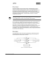
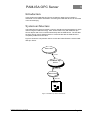
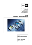
Structure
The implementation of the OPC interface specification is called the OPC Server.
Applications that use OPC servers are called OPC Clients. An OPC Client can
access multiple OPC Servers at the same time.
Figure 1: OPC Client/Server Relationship
PAM-ISA Opc Server User Manual
DOC 006.8036 Rev. May 22, 2000
Page: 7
OPC
INTERFACE
An OPC Server represents an image of a physical device. This is transparent for
the OPC Clients and they work with the OPC Server as if they were communicating
with the device directly.
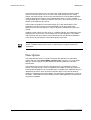
The OPC DataAccess is composed of three categories of objects: the server itself,
the group and the item.
An item represents a physical I/O or variable and is associated with attributes like
Name, Value, Quality and TimeStamp. Items are created by the OPC server and
can be accessed and changed by the OPC clients using read and write operations.
The OPC server maintains a cache of all the items of a device, which is kept up to
date automatically. The client usually accesses the cached item data in order to
optimize the communication load.
Groups are used to organize the items that an OPC Client wants to access. Items
are generally assigned to groups based on the update rate needed. Items are
updated and can be accessed only if they exist in at least one group.
Figure 2: Group/Item Relationship
An OPC server usually has multiple groups of two kinds: private and public groups.
Private groups are visible to only one client, whereas public groups can be used by
all clients.
Interface
Referring to the OPC server objects mentioned in the section above, there is a well
defined interface that can be used to access the server objects. This section
provides a short overview of the interfaces provided by the OPC DataAccess
specification. For detailed information on these interfaces, please refer to [2].
Since the OPC specification is based on the COM architecture, the interfaces
defined for the OPC server objects represents interfaces to COM components. Like
any COM component, OPC server objects also provide the IUnknown interface.
Beside this interface, the following interfaces are defined:
Page: 8
PAM-ISA Opc Server User Manual
DOC 006.8036 Rev. May 22, 2000
OPC
INTERFACE
Object
Interfaces
Server
IOPCCommon
IOPCServer
[IOPCServerPublicGroups]
[IOPCServerBrowseServerAddressSpace]
[IPersistFile]
[IConnectionPointContainer]
IOPCServerDisp
[IOPCServerPublicGroupsDisp]
[IOPCServerBrowseServerAddressSpaceDisp]
Group
IOPCItemMgt
IOPCGroupStateMgt
[IOPCPublicGroupStateMgt]
IOPCSyncIO
IOPCASyncIO2
IConnectionPointContainer
IOPCItemMgtDisp
IOPCGroupStateMgtDisp
[IOPCPublicGroupStateMgtDisp]
IOPCSyncIODisp
IOPCAsyncIODisp
Item
i
IOPCItemDisp
Interfaces written in brackets are defined to be optional, i.e. they don’t have to be
implemented to meet the OPC standard. However, the PAM-ISA Opc Server
supports all interfaces excepted the ones written in italic style.
There are two kinds of interfaces: custom interfaces and the automation interfaces.
Whereas the custom interfaces are used with programming languages like Visual
C++ and Java, the automation or dispatch interfaces (with ending …Disp) are
designed for script languages like Visual Basic or Java Script. These two kinds of
interfaces usually provide the same functionally and differ only in the way to use
them.
PAM-ISA Opc Server User Manual
DOC 006.8036 Rev. May 22, 2000
Page: 9
OPC
Page: 10
INTERFACE
PAM-ISA Opc Server User Manual
DOC 006.8036 Rev. May 22, 2000
PAM-ISA OPC Server
3
Introduction
In this section the PAM-ISA Opc Server provided by Atlas Copco Controls is
described in more detail. Information concerning the PAM-ISA device can be found
in the document [3].
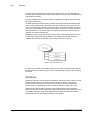
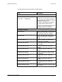
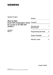
System architecture
The PAM-ISA Opc Server provides a common interface to the PAM device for OPC
clients using the COM technology. OPC clients interact only with PAM-ISA Opc
Server objects and never communicate directly with the PAM device. The fact that
the OPC Server uses a Windows driver to communicate with the PAM device is
completely hidden from the client.
Figure 3 shows the components used to access the PAM-ISA device via the PAMISA Opc Server.
OPC Client
COM
PAM-ISA Opc
Server
system call
windows driver
ISA bus
PAM-ISA
Figure 3: PAM-ISA Opc Server Architecture
PAM-ISA Opc Server User Manual
DOC 006.8036 Rev. May 22, 2000
Page: 11
DESCRIPTION
PAM-ISA OPC SERVER
The PAM-ISA Opc Server is an “out-of-process” COM component that is started
when the first OPC client tries to connect to the PAM-ISA Opc Server. During
startup, the PAM-ISA Opc Server scans the PAM device for all available variables
using the appropriate interface of the PAM Windows driver. For each variable a
corresponding item is created and stored in the cache. This is done only once in the
lifetime of the PAM-ISA Opc Server.
If the number of variables in the PAM changes (e.g. after downloading a new
application), the OPC Server must be terminated (i.e. all OPC clients must
disconnect from the OPC Server) in order to reload the variables during the next
startup.
Updating of item values is event driven. If a variable changes, the PAM informs the
PAM-ISA Opc Server which in turn updates the corresponding item. The update
rate defined by the OPC client is not considered in this case because PAM-ISA's
event driven concept keeps the item values always up to date.
i
The PAM-ISA Opc Server 1.0.xx does not support software download to the PAM
device. Software downloads are done via the serial port using the PAM Tools
application.
Description
The PAM-ISA Opc Server is a COM component that appears in the Windows
registry with the name ACC.PAMISA_OpcServer.20. Version 1.0.xx of the PAMISA Opc Server supports only the DataAccess interface defined by the OPC
specification.
The PAM-ISA Opc Server can be connected to only one PAM device. During
startup, the PAM-ISA Opc Server is initialized and creates an OPC item object for
each variable available on the connected PAM. A variable of the PAM-ISA device is
identified by its name, which is stored in the item object. There are two kinds of
variables: SystemInfo and UserVariables. The SystemInfo variables are common to
all PAM’s. UserVariables are the variables used in PAM applications and declared
as Channel Variables.
Page: 12
PAM-ISA Opc Server User Manual
DOC 006.8036 Rev. May 22, 2000
PAM-ISA OPC SERVER
DESCRIPTION
The PAM-ISA Opc Server provides the following items:
Name
Description
User variables
/CommId/<var ID>
One item for each Channel variable.
(See Table 5: SEQARABE)
<var ID> is a hex number to identify the
user variable. This id is defined with the
COMM_ID attribute of the
CHANNEL_REFERENCE declaration.
(for programming details see [5])
Channel variables declared as OUTPUT
are read only, channel variables
declared as INPUT are write only.
SystemInfo variables
/System/Reset
Used to reset the PAM. The PAM will be
reset each time a value not equal to
zero is written. Write only variable.
/System/State
State of the PAM device. Read only
variable. Please refer to appendix A for
details.
/System/NodeCount
Number of SAM’s connected to the
PAM. Read only variable.
/System/Bootware/Date
PAM bootware date of creation. Read
only variable.
/System/Bootware/Version
PAM boot ware version. Read only
variable.
/System/Bootware/CRC
PAM boot ware CRC. Read only
variable.
/System/Firmware/Date
PAM firmware date of creation. Read
only variable.
/System/Firmware/Version
PAM firm ware version. Read only
variable.
/System/Firmware/CRC
PAM firm ware CRC. Read only
variable.
/System/Application/Name
PAM application name. Read only
variable.
/System/Application/Date
PAM application date of creation. Read
only variable.
PAM-ISA Opc Server User Manual
DOC 006.8036 Rev. May 22, 2000
Page: 13
DESCRIPTION
PAM-ISA OPC SERVER
/System/Application/Time
PAM application time of creation. Read
only variable.
/System/Application/Version
PAM application version. Read only
variable.
/System/Application/CRC
PAM application CRC. Read only
variable.
/Driver/Version
Version of the PAM-ISA windows driver.
/Driver/Status
Status of the PAM-ISA windows driver.
Please refer to appendix A for details.
/Driver/Error
Error code of the PAM-ISA windows
driver. Please refer to appendix A for
details.
SystemInfo variables for SAM <n> connected to PAM (<n>: hex SAM address)
.Sam<n>/Bootware/Version
SAM boot ware version. Read only
variable.
.Sam<n>/Bootware/CRC
SAM boot ware CRC. Read only
variable.
.Sam<n>/Firmware/Version
SAM firm ware version. Read only
variable.
.Sam<n>/Firmware/CRC
SAM firm ware CRC. Read only
variable.
.Sam<n>/Application/Version
SAM application version. Read only
variable.
.Sam<n>/Application/CRC
SAM application CRC. Read only
variable.
.Sam<n>/Parameters/Version
SAM parameters version. Read only
variable.
.Sam<n>/ Parameters /CRC
SAM parameters CRC. Read only
variable.
Table 1:SEQARABE PAM-ISA Opc Server Items
Page: 14
PAM-ISA Opc Server User Manual
DOC 006.8036 Rev. May 22, 2000
4
PAM-ISA Opc Demo
Introduction
Atlas Copco Controls has prepared a demonstration that illustrates how the PAMISA Opc Server is used in practice. This demonstration utilizes the PAM-ISA Opc
Server Version 1.0.xx together with an OPC client sample application realized using
Excel.
This section describes how the demo application must be installed in order to run
the demonstration. The key parts of the Excel application are discussed in more
detail and use of the OPC automation interface with Visual Basic is explained.
System Requirements
The following system configuration is necessary to install and run the demo
application:
Hardware:
Pentium, 48 Mbyte RAM
PAM-ISA [p/n 9032 011 899]
PAM to PC Communications Cable [p/n 9032 011 929]
OS:
Microsoft Windows NT, Windows 98 or 2000
Software:
Microsoft Office 97
Atlas Copco Controls ProMotion V201-1
i
There’s no need to connect any SAM Drives to the PAM-ISA device in order to run
the demo application. But the optical ring must be closed by a single fibber
PAM-ISA Opc Server User Manual
DOC 006.8036 Rev. May 22, 2000
Page: 15
INSTALLATION
PAM-ISA OPC DEMO
Installation
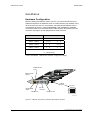
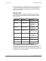
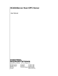
Hardware Configuration
Before installing the PAM-ISA card in your PC, you must insure that the port
address assigned to the PAM-ISA does not conflict with the port address of any
other device on the ISA bus. If necessary, the PAM-ISA port address can be
reconfigured as shown in Table 3:SEQARABE. After installing the PAM-ISA,
connect the PAM to PC Communications Cable between the PAM-ISA service
connector (see Figure 4) and designated PC COM connector.
Port Address
Address Jumpers
300 H – 307 H *
1 == 2
3 == 4
308 H – 30F H
1 == 2
3
310 H – 317 H
1
2
3 == 4
318 H – 31F H
1
2
3
notes :
*
4
4
factory default
== short circuit
Table 3:SEQARABE PAM-ISA Port Address Configuration Settings
Fault Indicator
(red)
Run Indicator
(green)
Address
jumpers
EasyBus IN
EasyBus OUT
4 2
output
3 1
FATAL ERROR
Top view
Service
connector
Pah018_a.cdr
Figure 4 PAM ISA Connectors, Indicators and Address Jumpers
Page: 16
PAM-ISA Opc Server User Manual
DOC 006.8036 Rev. May 22, 2000
PAM-ISA OPC DEMO
INSTALLATION
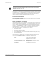
Be sure the power is switched off before installing or removing the
PAM-ISA card from your PC!
After installing the PAM-ISA card, insert the ProMotion Collection 1999-04 CD ROM
or newest collection, in your CD ROM Drive. ProMotion V201 or higher contains all
software necessary to install and run the demo as well as PAM Tools software
required to download the demo application program to the PAM.
Promotion Installation
From master-setup select Official versions and install ProMotion V201. Then install
the service pack 201-1 or higher
Demo Installation and Setup
The PAM-ISA Opc Demo can be installed on your hard disk using the master-setup
program included with the ProMotion CD. To run the setup program, insert the CD
into your CD drive and from the Evaluation versions menu page, select PAM-ISA
Opc Server. Setup will guide you through the installation and all files and registry
entries necessary to run the demo will be automatically installed on you PC.
Setup will install the following components on your machine:
•
PAM-ISA Opc Server
•
PAM-ISA Opc Demo Excel Sheet
•
Demo PAM application (must be downloaded to PAM_ISA using PAM Tools)
•
PAM-ISA windows driver
After installation, you will find in the ACC ProMotion folder of the Windows Start
menu the folder PAM-ISA Opc Server containing the following entries:
PAM-ISA Opc Server User Manual
DOC 006.8036 Rev. May 22, 2000
Demo
Link to the Excel Sheet Demo
application to start the demo
Uninstall PAM-ISA Opc Server
Remove complete installation of PAMISA Opc Demo
User Manual
User Manual in PDF-format
Page: 17
EXCEL SHEET APPLICATION
PAM-ISA OPC DEMO
PAM-ISA software configuration
Using PAM Tools, first check if you need to upgrade PAM bootware and firmware.
Check if tools displayed version is corresponding to the indicated version into
installed promotion readme.
The delivered demo application (D_pamisa.agl), located under ACC\pam-isa, must
be first compiled
After compilation, download D_pamisa.pai to the PAM-ISA using PAM Tools.
Then start the PAM, and check if the application is able to run. (The optical ring
must be closed by a single fiber)
Typical log messages when application is correctly synchronized with the PAM-ISA
Opc Server.
[0B80M105]
[0B80M106]
[0B80M10C]
[0B80M10D]
[0B80M10B]
[0B80M107]
Start Synchronisation
Synchronisation is done
Channel Bootware version D1=gesdp
1013
Channel Firmware version D1=gesdp
1013
Channel protocol D1=gesdp
PC based channel
Valid Application
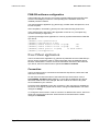
Excel Sheet application
The Excel sheet demo application (D_pamisa.xls) illustrates how the PAM-ISA Opc
Server can be accessed in order to collect information from the PAM-ISA device.
Because Visual Basic is used to access the automation interface of the PAM-ISA
Opc Server, the Excel sheet must be opened with Macros enabled!
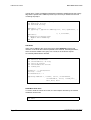
Connection
The Excel sheet must be connected to the PAM-ISA Opc Server, before the PAM
data can be accessed.
On the first line is listed the name of the PAM-ISA Opc Server which is set to
ACC.PAMISA_OpcServer.20 by default. To work with the PAM-ISA Opc Server
this name doesn’t have to be changed. But this could be the name of any OPC
server installed on your machine.
Press the button Connect to open the connection. If the connection is established,
the server name will be grayed and the button changes to Disconnect. The status
changes to ‘Ready’.
To change the server name in order to connect to a different OPC server, the Excel
sheet has to be disconnected first. Press Disconnect and wait until the status
changes to ‘Initialized’.
Page: 18
PAM-ISA Opc Server User Manual
DOC 006.8036 Rev. May 22, 2000
PAM-ISA OPC DEMO
EXCEL SHEET APPLICATION
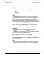
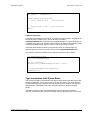
Description
After the Excel sheet is connected to the OPC server, the items can be accessed
and displayed. The demo sheet contains three parts to do so:
•
Item list
•
Refresh mode
•
Chart
Item list
The item list displays up to eight items. For each item the name and the value of
the corresponding PAM variable is shown. The item can be selected from the
combo box, which displays a list of all items currently available.
The current item value is displayed in the second column. This value can be
changed if the item is writable. To do so, select the corresponding text field, enter
the new value and deselect the text field by selecting any cell in the excel sheet. If
the access permission is read only, the value will be grayed and cannot be
changed.
If the item value is an array of multiple values (e.g. array of 8 bytes), only one
element of the array will be displayed. The element to display can be selected with
the spin box displayed next to the value. Values of arrays cannot be changed
although the access rights for the item would allow it.
Refresh mode
There are three refresh modes possible: Manual, Automatic or Record.
If the Manual refresh mode is selected, the Refresh button is activated. Each time
the Refresh button is pressed, all items displayed in the item list are read from the
OPC server and the corresponding values are updated.
In the Automatic mode, the OPC server informs the Excel sheet when a value has
been changed and the items are kept up to date automatically.
The Record mode enables periodic recording of the item values displayed in the
item list. By selecting this option, the Record chart is displayed and the Record
button is activated. Press this button to open a dialog for choosing the sample rate
and to start the recording.
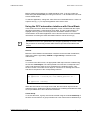
Chart
The chart provides a graphical representation of values displayed in the item list.
Only values of the type number can be shown correctly. There are two kinds of
charts:
In the Manual and Automatic refresh mode, a Column Chart is displayed. This
chart shows a vertical bar for each value where height corresponds to the item
value.
PAM-ISA Opc Server User Manual
DOC 006.8036 Rev. May 22, 2000
Page: 19
EXCEL SHEET APPLICATION
PAM-ISA OPC DEMO
In the Record refresh mode, a Line Chart is displayed. This chart contains a graph
of each value displayed in the item list, which shows the historical values of the
item. There are 100 samples recorded for each value. The first sample always
contains the latest value of an item. The time base depends on the sample rate
selected in the record dialog.
PAM application
The PAM demo application provided with the PAM-ISA Opc Server has eight
channel variables. If the demo application has been downloaded, eight items
appear in the drop down lists of the item list in the Excel spreadsheet. The item
names are as follows:
Variable Name
Item Name
Description
LRI_StartStop
CommId/0x010
Start/Stop demo
application (Default: 0)
LRI_Offset
CommId/0x020
Phase offset in
degrees added to the
SinShiftValue.
(Default: 0)
LRI_Limit
CommId/0x030
Max value for
RampValue. (Default:
0 -> not active)
LRI_ChangeRate
CommId/0x040
Change cycle in
milliseconds. (Default:
10)
LRI_IncrementSize
CommId/0x050
Value with which the
RampValue is
incremented each
cycle. (Default: 0.1)
LRO_RampValue
CommId/0x100
incremented value.
(Default: 0)
LRO_SinValue
CommId/0x110
sinus value. (Default:
0)
LRO_SinShiftValue
CommId/0x120
sinus value shifted by
offset. (Default: 0)
Table 5: SEQARABEChannel Variables Created by PAM Application
This PAM application is a simple application, which can be started and stopped with
the variable LRI_StartStop. When running, the variable LRO_RampValue is
incremented periodically then reset to zero when the limit LRI_Limit is reached. For
the LRO_SinValue, a sine signal is generated. The same signal shifted by the value
LRI_Offest is generated for LRO_SinShiftValue.
Page: 20
PAM-ISA Opc Server User Manual
DOC 006.8036 Rev. May 22, 2000
PAM-ISA OPC DEMO
EXCEL SHEET APPLICATION
Before starting the application, the PAM should be reset. To do this, select the
Reset item (see SEQARABE) and change its value to 1. All variables are now reset
to their default values.
To start the application, change the value of the item CommId/0x010 to a value not
equal to zero (e.g. 1). To stop the application set it back to zero.
Using the OPC automation interface with Visual Basic
In this section the Excel sheet demo application, which is realized with the scripts
language Visual Basic, is discussed in more detail. The aim of this section is to
highlight some key points concerning the OPC automation interface. Further
documentation of the demo application can be found in the source code. Detailed
information concerning the OPC automation interface can be found in [2].
i
In this example, the automation interface version 1.0 of the OPC DataAccess
specification is used. This specification has changed significantly in version 2.0 and
the procedure for accessing an item differs from the procedure described in this
section.
General
Before the OPC DataAccess automation interface can be used with Visual Basic,
make sure, that the type library OCSTK 1.0 Type Library is selected in the
reference list.
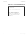
Connect
To connect to the OPC server, an appropriate COM object must be created using
the function CreateObject. The name passed to this function corresponds to the
name under which the OPC server is registered in the windows registry. This
function creates a new OPC server object or connects to an existing OPC server
and returns the pointer to the corresponding interface.
Dim gOpcServer As IOPCServerDisp
Set gOpcServer = CreateObject(“ ACC.PAMISA_OpcServer.20” )
…
…
Set gOpcServer = Nothing
When the OPC server is no longer to be used, the OPC server object must be
released properly. Setting the interface gOpcServer to Nothing terminates the OPC
server provided that no OPC clients are connected.
Create Group
To access the items, a group must first be created using the method AddGroup of
the OPC server interface. A group is defined as a set of items and is identified by a
PAM-ISA Opc Server User Manual
DOC 006.8036 Rev. May 22, 2000
Page: 21
EXCEL SHEET APPLICATION
PAM-ISA OPC DEMO
unique name. There are additional parameters passed to AddGroup like the activity
flag and the update rate. AddGroup returns (on success) an interface to the new
created group object.
Dim gOpcGroup As IOPCItemMgtDisp
Dim UpdateRate As Long
Dim ServerHdl As Long
UpdateRate = 500
Set gOpcGroup = gOpcServer.AddGroup("G1", True, UpdateRate, 1,
_
0, 0, ServerHdl,
UpdateRate)
If gOpcGroup Is Nothing Then
MsgBox "Error AddGroup"
End If
Add Items
Items can be added to the group using the method AddItems of the group
interface. A list of all item names is passed to this method, indicating the items,
which should be added to the group. As a result, a list of all item objects
successfully added will be returned.
Dim
Dim
Dim
Dim
Dim
Dim
itemIDs(1) As String
active(1) As Boolean
clientHandles(1) As Long
errors As Variant
serverHandles As Variant
itemObjects
itemIDs(0) = “ System/Reset”
active(0) = True
clientHandles(0) = 1
gOpcGroup.AddItems 1, itemIDs, active, clientHandles, _
serverHandles, errors, itemObjects, _
Null, Null, Null
Read/Write item value
To read or write the values of an item, the item objects returned by the method
AddItems can be used.
Dim opcItem As OCSItem
Dim value
Page: 22
PAM-ISA Opc Server User Manual
DOC 006.8036 Rev. May 22, 2000
PAM-ISA OPC DEMO
EXCEL SHEET APPLICATION
Set opcItem
= itemObjects(0)
if Not opcItem Is Nothing Then
value = opcItem.value ‘ read item value
…
…
…
opcItem.value = value ‘ write item value
End If
Callback registration
If the OPC client wants to be informed, if a value of an item changes, a callback can
be registered in the OPC server. This is done by the method
AddCallbackReference of the IOPCAsyncIODisp interface. A context id as well as
a callback object has to be passed to this method. The callback object must provide
a method ‘OnDataChange’ which is called in case a item value changes.
If the OPC client doesn’t want to be informed any more of a data change, the
callback reference can be removed with the method DropCallbackReference.
The interface IOPCAsyncIODisp can be optioned from the group interface.
Dim gConnection As Long
Dim aio As IOPCAsyncIODisp
Set aio = gOpcGroup
gConnection = aio.AddCallbackReference(1, Sheet1)
…
…
aio.DropCallbackReference gConnection
gConnection = 0
Type conversion with Visual Basic
The values provided by the PAM-ISA Opc Server are limited to the data types Real,
Integer and Boolean. But in some cases (e.g. the pam status), the value needs to
be interpreted byte wise. Whereas this conversion can easy be done with Integers
and Booleans, Visual Basic does not provide an interface to do this with Real
values.
Therefore within the setup of the PAM-ISA Opc Server an ActiveX Control is
included, which allows the conversion of Real values to Byte arrays and vice versa.
PAM-ISA Opc Server User Manual
DOC 006.8036 Rev. May 22, 2000
Page: 23
EXCEL SHEET APPLICATION
PAM-ISA OPC DEMO
To access this ActiveX Control, select the AccVBConv 1.0 Type Library in the
Visual Basic reference list. The following example illustrates how this interface has
to be used.
Dim
Dim
Dim
Dim
vBConv As AccVBConv
dval As Double
arrayRes As Variant
realRes As Variant
‘ Create the AccVBConv interface first
Set vBConv = CreateObject("ACCVBConv.AccVBConv")
dval = 123.567
‘ Convert dval to an 8 byte array
arrayRes = VBConv.ByteArrayFromReal(dval)
‘ arreyRes = {63, 53, 94, 186, 73, 228, 94, 64}
‘ Now convert the byte array back to a Real
realRes = VBConv.RealFromByteArray(arrayRes)
‘ realRes = 123.567
Page: 24
PAM-ISA Opc Server User Manual
DOC 006.8036 Rev. May 22, 2000
A
Appendix A
Status and Error Codes
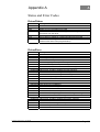
Driver/Status
Status Code
0xFFFFFFFF
0x01
0x02
0x04
0x08
0x10
0x20
Description
Error State
Uninitialized state: running device driver internal initialization
Waiting for synchronization from PAM
Initialization state: Download new application, Pam gets some
information from the driver
Watchdog is running and Messages are flowing through the dual port
Device driver is waiting for a reset command from the PAM
Special state indicating an access to the Jtag interface of the PAM
(PAM's FPGA and FLASH programmation)
Table 9: ..Driver Status Codes
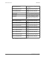
Driver/Error
Error Code
Description
0 OK
0x0D03001 Unknown error
0x0D03002 Not enough memory
0x0D03003 No device found on specified IO port
0x0D03004 Problem mapping the dual port memory
0x0D03005 Problem initializing the dual port memory
0x0D03006 Internal error: Unable to initialize the JTAG manager
0x0D03007 Internal error: Unable to initialize the command interpreter
0x0D03008 Internal error: Unable to initialize the state manager
0x0D03009 Internal error: Problem starting the message thread
0x0D0300A Internal error: Problem starting the watchdog thread
0x0D0300B Win32 client requesting an unknown variable
0x0D0300C Variable size mismatch
0x0D0300D Unable to access JTAG because of still active sessions
0x0D0300E JTAG is already being accessed
0x0D0300F JTAG access is not initialized
0x0D03010 Unable to initalize PAM application structures
0x0D03011 Internal error: GetData failed
0x0D03012 Internal error: Command interpreter: Unknown command
0x0D03013 Internal error: CHNL_CMD_DWNLOADBEG: Type not supported
0x0D03014 Internal error: Problem downloading data
0x0D03015 Pam->PC: Unknown DPID
0x0D03016 Internal error: Unable to initialize the session manager
0x0D03017 Internal error: Unable to initialize the session fifos
0x0D03018 Internal error: Unable to go to the specified state
0x0D03019 PC->Pam Dualport fifo full
0x0D0301A Pam->PC Windows fifo full
PAM-ISA Opc Server User Manual
DOC 006.8036 Rev. May 22, 2000
Page: 25
APPENDIX A
0x0D03100 PC->Pam Windows fifo full
0x0D03101 Internal error: Not enough memory
0x0D03102 New application detected. Variables list mismatch. Restart the OPC
server.
0x0D03103 Unable to initialize communicate with the Pam ISA device driver
0x0D03104 Internal error: Unable to create events
0x0D03105 Internal error: Unable to communicate with the Pam ISA device driver
0x0D03106 Unable to get information about application variables
0x0D03107 Internal error: Unable to initialize application variables
0x0D03108 Internal error: Unable to initialize Pam iSA common variables
0x0D03109 Number of SAM declared by the application does not correspond with
the actual hardware
0x0D0310A Internal error: Unable to start internal thread
0x0D0310B Unable to write variable. No active session
0x0D0310C Internal error: Uninitialized session manager has received a start cmd
0x0D0310D Internal error: Unable to initialize ORB
0x0D0310E Internal error: Unable to initialize ORB DPLink
Table 10 : ..Driver Error Codes
System/State
Status Code
0x01
0x02
0x03
0x04
Description
Booting State (stopped)
Running State
Fatal Error State
Busy (state transition)
Table 11: ..Pam Status Codes
Page: 26
PAM-ISA Opc Server User Manual
DOC 006.8036 Rev. May 22, 2000