1
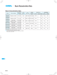
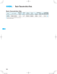
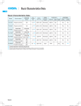
Basic Characteristics Data
Basic Characteristics Data
Model
GHA300F
GHA500F
GHA500F-SNF
Circuit method
Switching
frequency
[kHz]
boost chopper
60 - 220
LLC resonant converters
90 - 180
boost chopper
60 - 220
LLC resonant converters
90 - 180
boost chopper
60 - 220
LLC resonant converters
90 - 180
Inrush
current
protection
Material
3.3
Thermistor
FR-4
5.4
Thermistor
Aluminum/FR-4
5.4
Thermistor
Aluminum/FR-4
Input
current
*1 [A]
*1 The value of input current is at ACIN 120V and rated load.
*2 Parallel operation is available with –P option. Refer to 5.1on the instruction manual.
GHA
GHA-8
Series/Parallel
operation availability
PCB/Pattern
Single Double
sided
sided
Series
operation
Parallel
operation
Yes
Yes
No
Yes
Yes
Yes
*2
Yes
Yes
Yes
*2
AC-DC Power Supplies Medical Type Instruction Manual
1
2
3
Function
GHA-10
1.1
Input voltage range
GHA-10
1.2
Inrush current limiting
GHA-10
1.3
Overcurrent protection
GHA-10
1.4
Overvoltage protection
GHA-10
1.5
Thermal protection
GHA-10
1.6
Output voltage adjustment range
GHA-10
1.7
Output ripple and ripple noise
GHA-10
1.8
Isolation
GHA-11
Series Operation and Parallel Operation
GHA-11
2.1
Series Operation
GHA-11
2.2
Parallel Operation
GHA-11
Assembling and Installation Method
GHA-11
3.1
Heat dissipation (derating)
GHA-12
3.2
Installation method
GHA-13
3.3
Mounting screw
GHA-14
3.4
Expectancy life and warranty
GHA-14
3.5
Extermal capcitor on the output side
GHA-14
4
Ground
GHA-14
5
Option and Others
GHA-15
5.1
Outline of options
GHA-15
5.2
Medical Isolation Grade
GHA-17
5.3
Others
GHA-17
GHA
GHA-9
AC-DC Power Supplies Medical Type
Instruction Manual
Remarks :
1 Function
Please avoid applying a voltage exceeding the rated voltage to an
output terminal. Doing so may cause a power supply to malfunction or fail. If you cannot avoid doing so, for example, if you need
1.1 Input voltage range
to operate a motor, etc., please install an external diode on the
¡The range is from AC85V to AC264V or DC130V to DC370V
(please see SPECIFICATIONS for details).
¡In cases that conform with safety standard, input voltage range is
AC100-AC240V (50/60Hz).
(a) Recommended Capacity : 6.3A, slow -blow
DCIN
FUSE
L
N
Fig.1.1 Connection method
¡If input value doesn’t fall within above range, a unit may not operate in accordance with speci cations and/or start hunting or fail.
If you need to apply a square waveform input voltage, which is
commonly used in UPS and inverters, please contact us.
¡When the input voltage changes suddenly, the output voltage accuracy might exceed the speci cation. Please contact us.
1.2 Inrush current limiting
¡An inrush current limiting circuit is built-in.
¡If you need to use a switch on the input side, please select one
that can withstand an input inrush current.
¡Thermistor is used in the inrush current limiting circuit. When you
turn the power ON/OFF repeatedly within a short period of time,
please have enough intervals so that a power supply cools down
output terminal to protect the unit.
1.5 Thermal protection
¡Over Temperature Protection (OTP) is built in.
¡If this function is in operation, turn off power, eliminate all possible
causes of overheating, and drop the temperature to nomal level.
Output voltage recovers after applying input voltage.
The recovery time varies depending on input voltage and load
condition.
1Over rated temperature
2Poor ventilation
3Over peak load based on Instruction Manual 4. for Peak loading
Remarks :
Please comply with recommended mounting method in section
3.1.
1.6 Output voltage adjustment range
¡To increase an output voltage, turn a built-in potentiometeris clockwise. To decrease the output voltage, turn it counterclockwise
1.7 Output ripple and ripple noise
¡Output ripple noise may be in uenced by measurement environment, measuring method Fig.1.2 is recommended.
+Vout
before being turned on.
C1
¡Surge current in the lter unit does not include. (0.2ms or less).
-Vout
1.3 Overcurrent protection
cally recovers when a fault condition is removed.
Differential probe
Please do not use a unit in short circuit and/or under an overcur-
C1 : Film capacitor 0.1μF
rent condition.
C2 : Aluminum electrolytic capacitor 22μF
¡Intermittent Operation Mode
Intermittent operation for overcurrent protection is included in a
part of series. When the overcurrent protection circuit is activated
and the output voltage drops to a certain extent, the output becomes intermittent so that the average current will also decrease.
1.4 Overvoltage protection
Load
150mm
Osiloscope/
Ripple noise meter
Bw:20MHz
¡An overcurrent protection circuit is built-in and activated at 105%
of the rated current or 101% of the peak current. A unit automati-
GHA
C2 +
Fig.1.2 Measuring method of Ripple and Ripple Noise
Remarks :
When GND cable of probe with ux of magnetic force from power
supply are crossing, ripple and ripple noise might not measure
correctly.
Please note the measuring environment.
¡An overvoltage protection circuit is built-in. If the overvoltage protection circuit is activated, shut down the input voltage, wait more
than 3 minutes and turn on the AC input again to recover the output voltage. Recovery time varies depending on such factors as
input voltage value at the time of the operation.
Bad example
GHA-10
Good example
Fig.1.3 Example of measuring output ripple and ripple noise
Instruction Manual
AC-DC Power Supplies Medical Type
1.8 Isolation
¡For a receiving inspection, such as Hi-Pot test, gradually increase
(decrease) the voltage for the start (shut down). Avoid using HiPot tester with the timer because it may generate voltage a few
times higher than the applied voltage, at ON/OFF of a timer.
¡When you test a unit for isolation between the input and output,
input and the terminal FG or between the output and the terminal
FG, short-circuit between the output and the terminals RCG, PGG
and AUXG.
2 Series Operation and
Parallel Operation
¡Even a slight difference in output voltage can affect the balance
between the values of I1 and I2.
Please make sure that the value of I3 does not exceed the rated
current of a power supply.
I3 [ the rated current value
Please evaluate carefuly and test for any possible failure modes.
¡Hot-swap or Hot-plug is not available.
3 Assembling and
Installation Method
¡Features of the cooling method
¿ GHA500F
¡Cooling method
Conduction cooling, forced air and convection cooling are avail-
2.1 Series Operation
¡Series operation is available by connecting the outputs of two or
more power supplies with the same output voltage, as shown below. Output current in series connection should be lower than the
able.
The combination of the cooling method makes mechanical design
exible.
lowest rated current in each unit.
Remarks :
Please be sure to have enough cooling in case one of the power
Power +
Supply -
6) conduction cooling + forced air
(Variable speed FAN)
Load
Load
Power +
Supply -
: Heat dissipation
Load
Power +
Supply -
: chassis
FAN
supply stops due to activation of the protection circuitry.
Power +
Supply -
Combination
Fig.2.1 Examples of connecting in series operation
Seal case
FAN
2.2 Parallel Operation
¡Parallel operation
Parallel operation is possible with option ”-P”.
Parallel operation is not available for the standard unit, please refer to the listed options.
¡Redundancy operation
Redundancy operation is available by wiring as shown below.
Power +
Supply -
I1
I2
2) conduction cooling
Combination
3) forced air
Combination
I3
Load
Power +
Supply -
1) convection
Fig.2.2 Example of redundancy operation
4) convection + conduction cooling
5) conduction cooling + forced air
Fig.3.1 Cooling method Combination
In order to determine if the power supply operates according to
our speci cations, the maximum operating temperature and temperature measuring points are shown in table 3.1., for reference.
GHA-11
GHA
AC-DC Power Supplies Medical Type
Instruction Manual
¿ GHA300F
Remarks:
¡Cooling method
Both Forced air and convection cooling are available.
the power supply is used by the sealing up space as showing in
There is a possibility that it is not possible to cool enough when
Fig.3.3.
(Fig 3.1 1),3),6)cooling method).
Remarks:
Chassis
¡For proper operation of the power supply, please note the following:
1Heat dissipation (derating):Section 3.1 reference
-The temperature rise and heat dissipation of the converter must be
Power supply
Fig.3.3 Installation example
considered.
-Conditions varies with environment and input voltage.
-Mounting surface will be very hot during the operation ,so please
¿ GHA500F
be careful not to touch the surface.
(A) - (F) mounting
(*)
100
2Insulation distance: Please refer to Section 3.2
-AC voltage exist on the primary side therefore.
insolation distance.
3.1 Heat dissipation (derating)
80
Load factor [%]
-In order to prevent electric shock, or to meet the leakage current
requirements of the safety standard, you need to ensure the proper
60
40
20
¡Given the potential for variation between one application and another, the real test is to measure the critical components temperature
0
-20
rise when the power supply installed in the end-application.
-10
0
For reliable and safe operation, please make sure the maximum
component temperatures rise given in table 3.1 is not exceeded.
500
Power [W]
expectancy. The actual life expectancy can be extended by reduc-
2
3
4
450
400
350
Please contact us for more detail.
1
70
550
Operating at the maximum temperature rating results in 3-Years life
¡Test Measuring points
Be aware of the conductive parts during the measurements.
60
*Maximum power with Forced air (Fig.3.5)
ent cooling methods.
information.
50
Fig.3.4 Forced air cooling derating curve (Reference value)
Please refer to Fig.3.4 - 3.9 for derating information based on differ-
ing the ambient temperature. Please refer to section 3.4 for more
10
20
30
40
Ambient temperature [C]
5
8
6
7
0
GHA
MADE IN JAPAN
0
2.0
2.5
3.0
3.5
4.0
Wind velocity [m/s]
Fig.3.5 The maximum output power by wind speed conditions
100
(b)Lower substrate
Fig.3.2 Temperature measurement points locations
Table 3.1 Maximum operating temperature
GHA
Point
Parts name
Symbol
No.
1
2
3
4
5
6
7
8
Line Filter
Varistor
Input Capacitor
Output Capacitor
Rectifier
Transformer
Output Choke
Aluminum base plate
L101
SK101
C106
C506
SS11
T11
L51
-
Maximum
temperature[C]
500F
300F
115
115
76
76
89
89
87
87
120
120
110
110
115
115
*
Remarks
75
(C),(D),(E) mounting
(A) mounting
50
(B) mounting
(Pomax:150W)
25
(F) mounting
0
-20
case temperature
*Operating ambient temperature derating of Conduction cooling
(Reference value)
GHA-12
Load factor [%]
(a)Upper substrate
-10
0
10
20
30
40
Ambient temperature [C]
50
60
70
Fig.3.6 Convection cooling derating curve (Reference value)
Instruction Manual
AC-DC Power Supplies Medical Type
Load factor [%]
100
75
¡Mounting method
(B)
(A)
(Pomax:360W)
(C)
CN101
(A) - (F) mounting
CN101
50
CN101
Standard Position
25
CN101
0
-20
-10
0
10
20
30
40
50
60
70
(D)
(E)
(F)
80
Aluminum base plate temperature [C]
CN101
Fig.3.7 Conduction cooling derating curve (Reference value)
CN101
¿ GHA300F
100
Fig.3.11 Mounting method
(A) - (F) mounting
(Pomax:300W)
3.2 Installation method
Load factor [%]
80
¡During use, keep the distance between d1 & d2 for to insulate between lead of component and metal chassis, use the spacer of
60
5mm or more between d1. If it is less than d1 & d2, insert the insu-
40
lation sheet between power supply and metal chassis.
20
0
-20
¿ GHA500F
-10
0
10
20
30
40
Ambient temperature [C]
50
60
70
5mm min
Fig.3.8 Forced air cooling derating curve (Reference value)
Component side
100
Load factor [%]
75
(B),(C) mounting
(D),(E) mounting
d1
50
(Pomax:100W)
d1
d1
25
(A) mounting
0
-20
-10
0
d1
10
20
30
40
Ambient temperature [C]
50
60
d1=4mm min
70
Fig.3.9 Convection cooling derating curve (Reference value)
Fig.3.12 Installation method
¿ GHA300F
¡Input voltage derating curve
Derating curve depending on input voltage is Fig.3.10.
5mm min
For maximum power in each cooling method, please apply.
Component side
100
d2=5mmmin
Load factor [%]
90
80
d1
70
d1
GHA
d1
60
0
90
115
Input Voltage [V]
Fig.3.10 Input voltage derating curve
d1
d1=4mm min
Fig.3.13 Installation method
GHA-13
AC-DC Power Supplies Medical Type
3.3 Mounting screw
¡Warranty
¡The mounting screw should be M3. The hatched area shows the
allowance of metal parts for mounting.
¿ GHA300F, GHA500F
8
Instruction Manual
8
8
8
CN101
Table 3.4 Warranty (GHA500F-O)
Cooling
Method
Mounting
Method
Average ambient
temperature (year)
Ta = 35C or less
A, C, D
Ta = 40C
B
Ta = 45C
Convection
Ta = 30C or less
E
Ta = 35C
F
Ta = 30C
Ta = 40C or less
Forced air A,B,C,D,E,F
Ta = 50C
Warranty
Io[75%
75%<Io[100%
5years
5years
5years
3years
5years
5years
5years
5years
5years
4years
5years
5years
5years
4years
5years
3years
Table 3.5 Warranty (GHA300F-O)
8
8
8
8
Unit [mm]
Fig.3.14 Allowance of metal for mounting
¡If metallic ttings are used on the component side of the board,
ensure there is no contact with surface mounted components.
¡This product uses SMD technology.
Please avoid the PCB installation method which includes the twisting stress or the bending stress.
3.4 Expectancy life and warranty
¡Expectancy Life.
Table 3.2 Life Expectancy (GHA500F-O)
Cooling
Method
Mounting
Method
Average ambient
temperature (year)
Ta = 35C or less
A, C, D
Ta = 40C
B
Ta = 45C
Convection
Ta = 30C or less
E
Ta = 35C
F
Ta = 30C
Ta = 40C or less
Forced air A,B,C,D,E,F
Ta = 50C
Expectancy Life
Io[75%
75%<Io[100%
10years
6years
7years
4years
10years
7years
10years
7years
7years
5years
10years
7years
Over 10years
Over 10years
Over 10years
Over 10years
Table 3.3 Life Expectancy (GHA300F-O)
Cooling
Method
Mounting
Method
A
B, C
D
Convection
Average ambient
temperature (year)
Ta = 30C
Ta = 45C
Ta = 45C
Ta = 40C or less
E
Ta = 45C
Ta = 40C or less
Forced air A,B,C,D,E,F
Ta = 50C
Expectancy Life
Io[75%
75%<Io[100%
Over 10years
Over 10years
Over 10years
7years
Over 10years
Over 10years
Over 10years
7years
Over 10years
6years
Over 10years
Over 10years
Over 10years
Over 10years
Cooling
Method
Mounting
Method
A
B, C
D
Convection
Average ambient
temperature (year)
Ta = 30C
Ta = 45C
Ta = 45C
Ta = 40C or less
E
Ta = 45C
Ta = 40C or less
Forced air A,B,C,D,E,F
Ta = 50C
Warranty
Io[75%
75%<Io[100%
5years
5years
5years
5years
5years
5years
5years
5years
5years
4years
5years
4years
5years
3years
*Warranty with conduction cooling is three years at the highest point
of the temperature measurement.
3.5 Extermal capcitor on the output side
¡When the load currnet changes rapidly, for output stability improvement, we recommend that you connect the capacitor to the
output terminal.
Tabel 3.6 External capacity on the output recommended capacity [μF]
GHA300F-12
GHA500F-12
GHA500F-15
GHA300F-24
GHA500F-24
GHA500F-30
GHA300F-48
GHA500F-48
GHA500F-56
Output Voltage
[V]
Recommended
capacity
[μF]
10.8[Vo[13.2
2,200 to 22,000
13.5[Vo[16.5
2,200 to 10,000
21.6[Vo[26.4
3,300 to 8,800
27.0[Vo[31.5
43.2[Vo<51.0
51.0[Vo[52.8
52.0[Vo[56.0
3,300 to 8,800
0 to 1,000
0 to 120
0 to 120
Remarks:
When load current changes rapidly, some specifications may not
meet the spec.
Please mount power supply after enough evaluation and comply
with recommended amount of capacitor. If you exceed the rated
amount of capacitor, output for power supply may be stopped or
Remarks:
Estimated life expectancy can be calculated by point temperature
GHA
3 ,4 shown in section 3.1. Please contact us for details.
power supply may be unsteable.
4 Ground
¡In the case of the power installation, please be sure to connect
two or more Input FG and mounting hole FG with safety ground of
the chassis.
GHA-14
Instruction Manual
AC-DC Power Supplies Medical Type
5 Option and Others
¡Remote ON/OFF
-You can operate the remote ON/OFF function by sending
signals to CN501. Please see Table 5.3 for speci cations and
Fig.5.2 for connecting examples.
5.1 Outline of option
-Remote ON/OFF circuits (RC1 and RCG) are isolated from input,
output FG, AUX and PG.
¿ –J1
-Please note the followings when using the remote ON/OFF
function.
¡Connector(s) is / are replaced to VH connectors (Mfr.
J.S.T.).
1 -R3 turns on by drawing current to RC, –SNF turns off by drawing
current to RC.
¿ –R3, –SNF
2The current own to RC is a 5mA typ (maximum 30mA).
3If the output voltage is turned off through the remote ON/OFF
¡The following features are included.
¡Dedicated harness. Please refer to the optional parts.
¡AUX1 (12V±10% –R3 : 1.0A, –SNF : 0.5A)
-This power supply is equipped with an axuiliary low power 12V
output AUX1 which is available from CN501.
-AUX has been isolated from other circuit (input, output, FG, RC,
PG).
-Do not exceed the current rating, it may causes malfunction or
failure of the internal circuitry.
¡AUX2 (5V1A)
-Output AUX2 will be generated from CN501. AUX2 (5V±5%
1.0A) can be used to power up remote control or other circuits.
AUX has been isolated from other circuit (input, output, FG, RC,
PG).
circuit, 12V AUX stops.
4If the output voltage is turned off through the remote ON/OFF
circuit, PG signals turn to "High".
5If voltage or current of a value not listed in Table 5.3 is applied
between RC1 and RCG, the output voltage may not be generated
normally.
6Please wire carefully. If you wire wrongly, the internal components
of a unit may be damaged.
Table 5.3 Speci cations of remote ON/OFF
Fig.5.2 RC circuit example
Output on
SW Logic
Output off
-Do not exceed the current rating , it may causes malfunction or
failure of the internal circuitry.
-When the load currnet changes rapidly, for output stability improvement, we recommend that you connect the capacitor to
the output terminal.
recommended capacity [mF]
GHA300/500F
330 ~ 560
5V (AUX2)
¡Alarm
-Table 5.2, see Fig 5.1 the internal structure circuit explaining
the operation of the PG alarm.
Alarm output
Open collector method
Good : Low(0-0.5V 10mA max)
Bad : High or Open(40V 0.5mA max)
Tr : 40V 10mA max
(3mA min)
SW open
(0.1mA max)
SW close
or H-SN-35
(a)
(b)
AUX2
7
5V
440W 3
RC1 R1
4
RCG
8
AUX2G
7
V1
SW
5V
AUX2
440W 3
RC1
4
RCG
8
SW
AUX2G
CN501
CN501
(Example V1 : 5V R1 : 270W)
Table 5.2 Description of the alarm
Alarm output condition
Or lowering of the rated output
voltage, output PG, PGG from
terminal when you stop.
PG
*Output is unstable state
when the overcurrent
condition
–SNF
SW open
(0.1mA max)
(3mA min)
H-SN-34
Optional harness
Table 5.1 External capacitor on the recommended capacity of AUX2
Output Voltage
–R3
SW close
Fig.5.2 RC circuit example
* If the output of an external power supply is within the range of
4.5 - 12.5V, you do not need a current limiting resistor R1. If
the output exceeds 12.5V, however, please connect the current limiting resistor R1.
To calculate a current limiting resistance value, please use the following equation.
0.1mF
100kW
PG
R1[W]=
V1-(1.1+RiX0.005)
0.005
Ri=440[W]
GHA
Tr
PGG
Fig.5.1 Internal circuit of PG
GHA-15
Instruction Manual
AC-DC Power Supplies Medical Type
¿ –SNF
Expected lifetime [H]
1,000,000
¡Chassis and a cooling fan are added.
¡Oil and chemical environment may cause of power supply’s malfunction or failure. Please avoid operation and storage in such
environments.
¡Derating
It should be satis ed that derating curve depending on input volt-
100,000
10,000
age in Fig.3.10 and derating curve on ambient temperature in
20
30
40
50
60
70
80
FAN exhaust temperature [C]
Fig.5.4. As the veri cation method, temperature of measurement
point A should be rated temperature or less in Table 5.4.
Fig.5.5 Expected life time of FAN
20mm
FAN
7
1
Measurement point
2
8
Air flow
Power supply
(Top view)
Input
Point A
Output
Fig.5.3 Measurement point A
Fig.5.6 Measurement of FAN exhaust temperature
Table 5.4 Rated temperature of measurement point A
¡Mounting screw
Screw length into power supply should be shorter than 6mm due
Ambient temperature
50C
70C
65C or less
78C or less
Measurment
Point A
to keep safety isolation clearance from inside components in
Fig.5.7. Please x power supply surely by screws in consideration
of the weight.
100
Chassis of
customer system
Load factor [%]
80
Chassis of power supply
60
40
Screw M4
20
0
-20
6mm max
̂
0
10
20
30
40
50
60
70
Fig.5.7 Mounting screw
Ambient temperature [C]
Fig.5.4 Ambient temperature derating curve (Reference)
¡When output current more than rated, output may shut down after
5 seconds or more. Recycle the input after 3 minutes to reset the
¡A cooling FAN is built-in. Please keep 30mm or more clearance
both input and output side to make enough air ventilation. Do not
block off cooling FAN’s air ow for stable operation.
Air flow
protection.
If load wires are generating heat, intake air temperature may become high. It may in uence to FAN exhaust temperature. It is a
notice that optical wires have to be selected for the avoidance.
When FAN stop or air volume decrease happen, power supply’s
output will be shut down.
30mm
or more
Input
Output
(A)
GHA-16
Input
30mm
or more
Output
30mm
or more
Input
Output
30mm
or more
(B)
(C)
¡When power supply is used where dust exist, it may cause of FAN
failure. It is recommended to install a air lter to the system air
ventilation duct.
GHA
30mm
or more
FAN
perature from FAN at input terminal side.
Air flow
measurement point temperature in Fig.5.6, which exhaust air tem-
30mm
or more
Air flow
¡Maintenance of FAN
FAN life time expectancy (R(t)=90%) in Fig.5.5 is depended on
AC-DC Power Supplies Medical Type
¿ –T3
Instruction Manual
5.3 Others
¡M3 threaded mounting hole is available as an option (–T3).
: Tap
¡High voltage exist in the power supply for a few minutes after
input voltage is stopped. Please pay attention to this during the
maintence.
¡Notes for mounting
1All Mounting holes should be tight and secured.
Case
(a) T3 (Threaded mounting hole)
(b) Standard (Through hole)
Fig.5.8 Screw mounting image
2Power supply should be mounted parallel to the mounting surface.
3Avoid applying mechanical stress or shock to the power supply.
¡When power supply is energized or immidately after power supply
stops working, power supply is still very hot, so please handle it
with care.
¿ –P
¡Parallel operation is available (Recommended two).
¡Output wattage setting is 90% per power supply of MAX OUTPUT
WATTAGE.
Remarks:
-The difference of output voltage between power supply for parallel operation should be less 0.1V.
-During parallel operation, higher voltage power supply become
the master in system. Depend on voltage difference between
master and slave, the master power supply may recover the
system’s required wattage up to 90% of MAX OUTPUT WATTAGE.
The master unit should be evaluated for heat dissipation, life
expectancy and warranty period according to section 3.1 - 3.4.
-Parallel operation, due to the uctuation of load, the output voltage may be varied.
There is a possibility that beat noise occurs due to the difference
of the oscillation frequency. Please use after enough evaluation.
-Forced air cooling is required.
-Input voltage ought be AC115V or more.
5.2 Medical Isolation Grade
¡GHA series t 2MOPP
2MOPP
primary secondary
1MOPP
Safety GND
Fig.5.9 Medical Isolation Grade
GHA
GHA-17