1
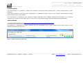
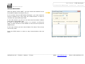
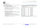
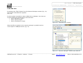
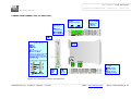
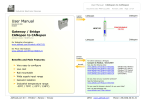
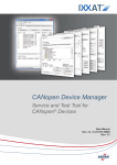
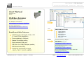
User Manual
Document code: MN67216_ENG
CAN Analyzer
Revision 4.110
Page 1 of 24
Electronic Devices
User Manual
Revision 4.110
English
CAN Bus Analyzer
(Order Code: HD67216)
for Website information:
www.adfweb.com?Product=HD67216
Software
for Price information:
www.adfweb.com?Price=HD67216
Tools
CAN bus Monitor
CANopen Monitor
CAN sender
Network Manager
COB-ID filter
SDO and PDO filter
Mask filter
Benefits and Main Features:
CAN Analyzer Advanced 2.0A, 2.0B
(11 and 29 bit identifier);
Free updating to lifetime;
Master DeviceNet utility;
Opto-isolated CAN port;
HW filter for CAN/CANopen packet;
CAN/CANopen Tools:
Similiar
Products
For others Gateways / Bridges:
CAN /RS232
See also the following link:
www.adfweb.com?Product=HD67190
Do you have an your customer protocol?
MAX baud rate 1Mb;
See the following links:
www.adfweb.com?Product=HD67003
Industrial temperature range
-30°C / 70°C (-22°F / 158°F)
Do you need to choose a device? do you want help?
Ask it to the following link:
www.adfweb.com?Cmd=helpme
________________________________________________________________________________________________________________
Phone +39.0438.30.91.31
ADFweb.com Srl – IT31010 – Mareno – Treviso
INFO: www.adfweb.com
User Manual
Document code: MN67216_ENG
CAN Analyzer
Revision 4.110
Page 2 of 24
Electronic Devices
INDEX:
UPDATED DOCUMENTATION
REVISION LIST
WARNING
TRADEMARKS
INDEX
INTRODUCTION
THE SOFTWARE
BAUD RATE OF THE BUS
CAN MONITOR
CAN SENDER
MASTER DEVICENET
CANOPEN MONITOR
NETWORK MANAGER
LOAD EDS FILE
BASIC CONCEPTS ABOUT CAN
BASIC CONCEPTS ABOUT CANOPEN
ABORT CODE DESCRIPTION
UPDATE NEW FIRMWARE
CONNECTION SCHEME
CHARACTERISTICS OF THE CABLES
MECHANICAL DIMENSIONS
ORDER CODE
ACCESSORIES
WARRANTIES AND TECHNICAL SUPPORT
RETURN POLICY
PRODUCTS AND RELATED DOCUMENTS
UPDATED DOCUMENTATION:
Page
2
2
2
2
2
3
3
5
6
9
10
11
13
14
15
16
19
20
21
22
23
23
23
24
24
24
Dear customer, we thank you for your attention and we remind you that you need
to check that the following document is:
Updated
Related to the product you own
To obtain the most recently updated document, note the “document code” that
appears at the top right-hand corner of each page of this document.
With this “Document Code” go to web page www.adfweb.com/download/ and
search for the corresponding code on the page. Click on the proper “Document
Code” and download the updates.
To obtain the updated documentation for the product that you own, note the
“Document Code” (Abbreviated DC on the product’s box) and download the updated
from our web site www.adfweb.com/download/
REVISION LIST:
Revision
Date
Author
Chapter
Description
1.005
19/06/2006
Ddt
All
2.000
06/04/2007
Av
All
documentation code
changed
New software version
2.001
11/04/2007
Av
All
Discontinued software
2.002
22/06/2007
Av
All
Revision
3.000
25/06/2007
Av
All
New software version
3.001
26/06/2007
Av
All
Revision
4.000
05/07/2007
Av
All
New document format
4.001
11/07/2007
Av
All
Change accessories code
4.100
23/01/2008
Av
New software version
4.110
14/02/2008
Av
Load EDS file
Basic concepts
about CAN
Revision
WARNING:
ADFweb.com reserves the right to change information in this manual about our
product without warning.
ADFweb.com is not responsible for any error this manual may contain.
TRADEMARKS:
All trademarks mentioned in this document belong to their respective owners.
________________________________________________________________________________________________________________
Phone +39.0438.30.91.31
ADFweb.com Srl – IT31010 – Mareno – Treviso
INFO: www.adfweb.com
User Manual
Document code: MN67216_ENG
CAN Analyzer
Revision 4.110
Page 3 of 24
Electronic Devices
INTRODUCTION:
The CAN Analyzer is a powerful, flexible and economic instrument which develops and verifies system based in CANCANopen.
This product allows for the study and configuration of CANopen systems, using a user interface that permits a simple
access to devices and their objects.
The instrument is composed of the following: module hardware with a RS232 interface that connects to a personal
computer and a CAN terminal that connects to the line; a Null modem serial cable and software for MS Windows.
THE SOFTWARE:
To obtain software please go to http://www.adfweb.com/home/download/download.asp.
(This manual is referenced to the last version of the software present on our web site)
The software is composed of various windows that are controllable from a main window which allows access to the
different CAN Analyzer functions.
Figure 1: Main window for SW67216
________________________________________________________________________________________________________________
ADFweb.com Srl – IT31010 – Mareno – Treviso
INFO: www.adfweb.com
Phone +39.0438.30.91.31
User Manual
Document code: MN67216_ENG
CAN Analyzer
Revision 4.110
Page 4 of 24
Electronic Devices
Status Desc indicates:
Packet receive: the number of CAN bus packages received from the hardware device.
Packet discarded Filter: the number of the CAN bus packages discarded from the hardware device.
Packet error controller the number of CAN bus packages discarded erroneously from the Controller CANbus.
Send Filter - Bad Filter - Filter Ok: the state of the filter configurable from the software.
Status LED indicates:
Cr: Color gray if the CAN Bus network was not activated
Tr : Color red if sending data to the Hw CAN Analyzer device
Tp: Color red if the CAN Transmitters are occupied
Ov : Color red if overwriting is verified within the receive CAN
Wl : Color red if there are communications errors on the CAN during transmission and reception
Bo : Color red if the CAN bus network is always in error.
The Bus Load indicates the load level on the line. Normally, a line does not carry a load over 30%. A long period of time with an abnormal
load may indicate that the applications are excessively using the BUS.
This could be caused by an incorrect cable connection (use of the terminal resistors) or the presence of device that functions at a different
BAUD RATE than the one set in the analyzer.
The “menu” and “tool bar” access a series set-up possibilities such as:
communication configuration
baud rate of the bus
turning on and off the hardware.
________________________________________________________________________________________________________________
ADFweb.com Srl – IT31010 – Mareno – Treviso
INFO: www.adfweb.com
Phone +39.0438.30.91.31
User Manual
Document code: MN67216_ENG
CAN Analyzer
Revision 4.110
Page 5 of 24
Electronic Devices
BAUD RATE OF THE BUS:
In this menu is possible set the baud rate of the bus and set the
protocol (Standard and extended):
Standard is CAN2.0A and extended is CAN2.0B.
The “Form list” controls the opening of the windows that access
the various CAN Analyzer functions.
The “CAN Monitor” is a window that allows the visualization of the
BUS data at the package level.
The “CAN Sender” is a window that allows CAN packages to be
send into CAN line.
The “CANOpen Monitor” is a window that allows for the
visualization of BUS data, interpreting it as CANopen packages.
The “Network Manager” is a window that allows for control of the
CANopen modules inserted in the line. It can scan the network to
find modules and for each one, it reads the object dictionary.
Figure 2: “Setting Can” window
________________________________________________________________________________________________________________
ADFweb.com Srl – IT31010 – Mareno – Treviso
INFO: www.adfweb.com
Phone +39.0438.30.91.31
User Manual
Document code: MN67216_ENG
CAN Analyzer
Revision 4.110
Page 6 of 24
Electronic Devices
CAN MONITOR:
It is the window that allows the visualization of the BUS data at
the package level and its columns mean the following:
Time: indicates the time in which data is received
Id: indicates the Identifier
Data: indicates the data byte of the CAN package ( they
can be from 0 to 8 )
ASCII: representations of the received data in ASCII char.
the buttons on the tool bar allow the following actions:
“Export Excel”: allows for the exportation of the entire
content of the grid as a text file.
“CAN Start” and “CAN Stop”: activate or stop the writing of
the packages in the grid.
“Clear” eliminates the grid content.
“Lock Recent Entities” visualizes the last CAN package.
“Scroll/Overwrite Mode”: serves in the choice to write all
packages one after another in the grid or to write all of
them in the same row.
“Filter” opens the window for filter set-up.
The filter is an instrument that allows the hardware module to
eliminate package that it does not want to be visualized in the
CAN Monitor Window. (Note: the filter reacts on the Identifier
section of the package)
By pressing the “Filter” button from the “Can Monitor” window
the “Filter” window appears (Fig. 4):
On the set-up windows for the filter, there are two lists:
on the right, the list of the Identifiers ($0-$7FF) of the
packages to be visualized.
On the left, those lists to be eliminated.
To modify the lists, use the keys “<<”, “>>”, “ALL” and
“NONE” to move an Identifier from one list to another, bring
them to the right (shown) or the left (hidden).
Figure 3: “Can Monitor” window
Figure 4: “Filter” window
________________________________________________________________________________________________________________
ADFweb.com Srl – IT31010 – Mareno – Treviso
INFO: www.adfweb.com
Phone +39.0438.30.91.31
User Manual
Document code: MN67216_ENG
CAN Analyzer
Revision 4.110
Page 7 of 24
Electronic Devices
When the protocol is extended by pressing the “Filter” button
from the “Can Monitor” window the “Filter” window appears
(fig 5):
This window is for setting COB-ID Filter.
In this
window there are:
A text area on the left for insert the COB-ID in the filter
A big area on the right for display the COB-ID inserted
Two buttons for add or delete the COB-ID
Two options for set the filter to “type positive” or “type
negative”
For insert a COB-ID in the filter you have to digit the COB-ID in
the first text area and click on the “add” button. Now the COB
ID compare on the right box.
For delete a COB-ID you have to select the COB-ID to remove
and click on the “delete” button.
You can choose two type of the filter: positive or negative, by
clicking on the relative option.
With the positive type filter on the CAN monitor you visualize
only the COB-ID added
With the negative filter type on the CAN monitor you visualize
all COB-ID except the COB-ID added
Figure 5: COB-ID Filter window
________________________________________________________________________________________________________________
ADFweb.com Srl – IT31010 – Mareno – Treviso
INFO: www.adfweb.com
Phone +39.0438.30.91.31
User Manual
Document code: MN67216_ENG
CAN Analyzer
Revision 4.110
Page 8 of 24
Electronic Devices
By clicking on “Mask Filter” appears this window:
In this window you can set a mask filter.
In the first text area you can write the COB-ID to add to the
list. The COB-ID must be in binary code.
When you insert the COB-ID you can insert some variables (x),
the variable can be 0 or 1.
Example:
COB-ID
“10xx11”
On the CAN monitor you can visualize the following COB-ID:
100011
100111
101011
101111
You can insert also the COB-ID without variables, in this way:
Example 2:
COB-ID is 110100
On the CAN monitor you can visualize only the COB-ID 110100
Figure 6: Mask Filter window
You can add or delete the COB-ID by clicking on the relative
buttons.
________________________________________________________________________________________________________________
ADFweb.com Srl – IT31010 – Mareno – Treviso
INFO: www.adfweb.com
Phone +39.0438.30.91.31
User Manual
Document code: MN67216_ENG
CAN Analyzer
Revision 4.110
Page 9 of 24
Electronic Devices
CAN SENDER:
It allows for data to be send in the network. The package is
built by its Identifier and its data.
The window allows a list of packages to be created, then
are visualized on the grid.
To add a new package, write the values in the text fields
and then choose “Edit New”. The new package extends the
table at the first available row. Otherwise, to modify a row,
select it and choose the option “Edit Modify”. “Edit del”
eliminates the selected row.
From the “Function Menu”, choose “Transmit Current
Object” to send the package one single time. Choose
“Transmit Cycle” to send it cyclically.
The “Debug” function send only the selected package, if the
main checkbox on top is checked. For select the package
to be sent you have to check the debug on the end of the
line.
Figure 7:“Can Sender” window
The function “Transmit cycle” automatically sends the CAN package
every X millisecond set-up on the provided window by pressing the
button above the cycle column in the grid or menu options “Cycle
Options”.
By pressing the “Transmit cycle” button from the “Can Sender”
window the “Cycle Options” window appears (Fig. 8):
The set-up window allows for the choice of the time intervals between
sending two packages and the byte to begin sending the package.
Once the package to be sent are set-up: select the row dedicated
to the package to be send and click on the transmission:
“TX” to send one time
and “TX Cycle” to send cyclically, if the Cycle Options are setup.
Figure 8: “Cycle Options” window
________________________________________________________________________________________________________________
ADFweb.com Srl – IT31010 – Mareno – Treviso
INFO: www.adfweb.com
Phone +39.0438.30.91.31
User Manual
Document code: MN67216_ENG
CAN Analyzer
Revision 4.110
Page 10 of 24
Electronic Devices
MASTER DEVICENET:
With the button “Device NET”, you can access the window for the
DeviceNET’s Master simulation (Fig. 9).
In the window “Device NET Master Emulator”, you must write the
device’s address only, then push the START button in order to
visualize the input and output data.
In the left column you can put the data that DeviceNet’s Master
must write in DeviceNET’s net.
In order to change the data’s value, it is enough: to select the
data, to write its value in the editbox on the list and to push the
SEND button.
In the right column you can view all data of the slave. This column
can be only read.
Push the STOP button in order to stop communication with the
slave.
Figure 9: “DeviceNET Master Emulator” window
________________________________________________________________________________________________________________
ADFweb.com Srl – IT31010 – Mareno – Treviso
INFO: www.adfweb.com
Phone +39.0438.30.91.31
User Manual
Document code: MN67216_ENG
CAN Analyzer
Revision 4.110
Page 11 of 24
Electronic Devices
CANOPEN MONITOR:
It is a window that allows the BUS data to be visualized, interpreting
the data as specified by the CANopen.
The columns mean the following:
Time: Indicates the time that data is received
Node: Address of the device associated with the package
( 1-127 )
Object: Indicates the type of object
Data: Indicates the data related to the package (the contents
depend on the type of package).
The tool bar allows for the following actions:
“Export Excel”: allows for the exportation of the entire
contents of the grid as a text file.
“CAN Start” and “CAN Stop”: activate or stop the writing of
the packages in the grid.
“Clear” eliminates the grid content.
“Lock Recent Entities” visualizes the last CAN package.
“Scroll/Overwrite Mode”: serves in the choice to write all the
packages one after another in the grid or to write all of them
in the same row.
“Filter” opens the window for filter set-up.
Figure 10: “Canopen Monitor” window
________________________________________________________________________________________________________________
ADFweb.com Srl – IT31010 – Mareno – Treviso
INFO: www.adfweb.com
Phone +39.0438.30.91.31
User Manual
Document code: MN67216_ENG
CAN Analyzer
Revision 4.110
Page 12 of 24
Electronic Devices
The filter is an instrument that allows the hardware module to
eliminate package that it does not want to visualized in the CANOpen
Monitor Window.
By pressing the “Filter” button from the “CanOpen Monitor” window
the “Filter” window appears (Fig. 11):
The set-up window of the filter allows every type of package to be
visualized or not based on a specific address.
The CANopen monitor window is valid only for standard protocol.
Figure 11: “Filter” window
________________________________________________________________________________________________________________
ADFweb.com Srl – IT31010 – Mareno – Treviso
INFO: www.adfweb.com
Phone +39.0438.30.91.31
User Manual
Document code: MN67216_ENG
CAN Analyzer
Revision 4.110
Page 13 of 24
Electronic Devices
NETWORK MANAGER:
The “Network Manager” windows allows certain operations, designed
for the analysis of CANopen devices.
It is possible to scan the network through this window.
In order to identify the presence of module within the network, it is
possible to read the objects of a module’s Object Dictionary and send
the start package to the network.
Set-up the range of addresses for the scan in order to scan the
network.
Figure 12: “Network Manager” window
Press the “Scan” button and wait for this scan. The list of the node is
filled in with the found nodes. These can be added to the Index and
SubIndex.
The button “Add Node”, “Add Index”, “Add SubIndex”, “Modify” and
“Delete” allow for the elaboration of the objects list.
To read the value of an object through SDO, select the object from
the list and press the button “Read” and the button “Write” to write
it.
The Network manager window is valid only for standard protocol.
Figure 13: “Scan range” window
________________________________________________________________________________________________________________
ADFweb.com Srl – IT31010 – Mareno – Treviso
INFO: www.adfweb.com
Phone +39.0438.30.91.31
User Manual
Document code: MN67216_ENG
CAN Analyzer
Revision 4.110
Page 14 of 24
Electronic Devices
LOAD EDS FILE:
By pressing the “EDS” button from the Network Manager window (Fig. 12)
the window “Load EDS file” appears
(Fig. 14):
By this window is possible to load an EDS file for CANopen. Can also set
as part of EDS you would load by check the field:
• Insert Mandatory object
• Insert optional object
• Insert manufacturer object
Figure 14: “Load EDS File” window
When the EDS is loaded on the network manager is possible see the
varius object of CANopen device (fig. 15)
Figure 15: “Network Manager” window with EDS file
________________________________________________________________________________________________________________
ADFweb.com Srl – IT31010 – Mareno – Treviso
INFO: www.adfweb.com
Phone +39.0438.30.91.31
User Manual
Document code: MN67216_ENG
CAN Analyzer
Revision 4.110
Page 15 of 24
Electronic Devices
BASIC CONCEPTS ABOUT CAN:
The CAN Bus is a bus that use simple twisted cable as a physical support. It allows for the communications between several devices at
the same time on the same network through an automatic control on the part of the hardware driver, package priority. It is used often
in the automotive field and by automated industry.
A CAN
package is composed of several parts:
11/ 29 bits of the Identifier,
up to 8 bytes of data
and other CRC bits.
The COB-ID serves to define the priority of the BUS package (note: the lower the values, the higher the bus priority).
The COB-ID bits are, in effect, defined as dominant if zero and recessive if one.
The CAN Hardware Driver and the CAN Controller (generally, the microprocessor) if there is an error during the transmission of the
package, they suspend the transmission and recuperate the information automatically. This automation permits a high level of security
and therefore is used in critical situations.
________________________________________________________________________________________________________________
ADFweb.com Srl – IT31010 – Mareno – Treviso
INFO: www.adfweb.com
Phone +39.0438.30.91.31
User Manual
Document code: MN67216_ENG
CAN Analyzer
Revision 4.110
Page 16 of 24
Electronic Devices
BASIC CONCEPTS ABOUT CANOPEN:
The CANopen is a protocol based on CAN that defines a series of set-up rules for package and interactions in which devices can
communicate.
Also, CANopen brings to the generation of profiles made to standardize communication with generic modules such as I/O, Encoder, etc.
Above all, CANopen defines diverse typologies of the package, distinguished base on the COB-ID of the CAN Package (see the table
below).
COB-ID
$00
Network management
$80
Sync
$80+devadd
Emcy
$180+devadd
$200+devadd
txPDO 1 rxPDO 1
$280+devadd
$300+devadd
txPDO 2 rxPDO 2
$380+devadd
$400+devadd
txPDO 3 rxPDO 3
$480+devadd
$500+devadd
txPDO 4 rxPDO 4
$700+devadd
Nodeguarding
$600+devadd
$580+devadd
SDO request SDO response
In the table, for every package “devadd” (the device address), there is a value up to $7F. A CANopen network can have up to 127
devices (“devadd” begins from 1).
_____________________________________________________________________________________________________________
___
ADFweb.com Srl – IT31010 – Mareno – Treviso
INFO: www.adfweb.com
Phone +39.0438.30.91.31
User Manual
Document code: MN67216_ENG
CAN Analyzer
Revision 4.110
Page 17 of 24
Electronic Devices
We add a brief description of the meaning of the 8 bytes of data for each type of package.
Network management (Cob ID 0x00)
Byte 1 :
Identifies the type of command
Byte 2 :
Identifies the node that receives the command
Byte 3-4-5-6-7-8 :Reserved
Sync Message (Cob ID 0x80)
Byte 1-2-3-4-5-6-7-8 :
Absent
Emergency Object (Cob ID 0x80 - 0xFF )
Byte 1 : LSB Error Code
Byte 2 : MSB Error Code
Byte 3 : Error Register
Byte 4-5-6-7-8 : Manufacturer Specific Error Field
Timestamp Message (Cob ID 0x100)
Byte 1-2-3-4 :
time expressed in milliseconds
Byte 5-6 :
Number of days
Byte 7-8 :Reserved
Transmit Pdo n° 1 Cob ID 0x180 a 0x1FF
Byte 1-2-3-4-5-6-7-8 : databytes
Receive Pdo n° 1 (Cob ID 0x200 a 0x27F)
Byte 1-2-3-4-5-6-7-8 : databytes
SDO Read Response (Cob ID 0x580 a 0x5FF )
Byte1 : 010X.YY11 (0x40)
YY
Indicates how many byte of the 4 data possibilities do not
contain data.
X
Indicates a bit which has an indifferent value (don’t care)
Byte 2 : index byte low
Byte 3 : index byte hight
Byte 4 : subindex
Byte 5,6,7,8 : Data bytes
SDO Read Request (Cob ID 0x600 a 0x67F )
Byte1: 010X.XXXX (0x40)
X
Indicates a bit which has an indifferent value (don’t care)
Byte 2 index byte low
Byte 3 index byte hight
Byte 4 subindex
Byte 5,6,7,8 Reserved
SDO Write Response (Cob ID 0x580 a 0x5FF )
Byte1 : 011X.XXXX (0x60)
Indicates a bit which has an indifferent value (don’t care)
Byte 2 : index byte low
Byte 3 : index byte high
Byte 4 : subindex
Byte 5,6,7,8 : Data bytes
________________________________________________________________________________________________________________
ADFweb.com Srl – IT31010 – Mareno – Treviso
INFO: www.adfweb.com
Phone +39.0438.30.91.31
User Manual
Document code: MN67216_ENG
CAN Analyzer
Revision 4.110
Page 18 of 24
Electronic Devices
SDO Write Request (Cob ID 0x600 a 0x67F)
Byte1 : 001X.YY11 (0x20)
YY
Indicates how many byte of the 4 data possibilities do not
contain data.
X
Indicates a bit which has an indifferent value (don’t care)
Byte 2 : byte index byte low
Byte 3 : byte index byte hight
Byte 4 : subindex
Byte 5,6,7,8 : Reserved
SDO Abort (CobID 580+id)
CobID 600+id
Byte 1 100X.XXX (0x80)
Byte 2 index byte low
Byte 3 index byte high
Byte 4 subindex
Byte 5,6 Additional code
Byte7 Error code
Byte 8 Error class
Codici Error class
00 NO ERROR
05 SDO SERVICE
06 SDO ACCESS
08 SDO OTHER
Error code :
01 UNSUPP_ACCESS
02 NONEXIST_OBJECT
03 INCONS_PARA
04 ILLEG_PARA
06 HARDWARE_FAULT
07 TYPE_CONFLICT
09 INCONS_OBJ_ATTR
0A RES_NOT_AVAIL
________________________________________________________________________________________________________________
ADFweb.com Srl – IT31010 – Mareno – Treviso
INFO: www.adfweb.com
Phone +39.0438.30.91.31
User Manual
Document code: MN67216_ENG
CAN Analyzer
Revision 4.110
Page 19 of 24
Electronic Devices
ABORT CODE DESCRIPTION:
0503
0504
0504
0504
0504
0504
0504
0601
0601
0601
0602
0604
0604
0604
0604
0606
0607
0607
0607
0609
0609
0609
0609
0609
0800
0800
0800
0800
0800
0000h
0000h
0001h
0002h
0003h
0004h
0005h
0000h
0001h
0002h
0000h
0041h
0042h
0043h
0047h
0000h
0010h
0012h
0013h
0011h
0030h
0031h
0032h
0036h
0000h
0020h
0021h
0022h
0023h
Toggle bit not alternated.
SDO protocol timed out.
Client/server command specified not valid or unknown.
Invalid block size (block mode only).
Invalid sequence number (block mode only).
CRC error (block mode only).
Out of memory.
Unsupported access to an object.
Attempt to read a write only object.
Attempt to write a read only object.
Object does not exist in the object dictionary.
Object cannot be mapped to the PDO.
The number and length of the objects to be mapped would exceed PDO length.
General parameter incompatibility reason.
General internal incompatibility in the device.
Access failed due to an hardware error.
Data type does not match, length of service parameter does not match.
Data type does not match, length of service parameter too high.
Data type does not match, length of service parameter too low.
Sub-index does not exist.
Value range of parameter exceeded (only for write access).
Value of parameter written too high.
Value of parameter written too low.
Maximum value is less than minimum value.
general error.
Data cannot be transferred or stored to the application.
Data cannot be transferred or stored to the application because of local control.
Data cannot be transferred or stored to the application because of the present device state.
Object dictionary dynamic generation fails or no object dictionary is present (e.g. object dictionary is generated from file
and generation fails because of a file error).
________________________________________________________________________________________________________________
ADFweb.com Srl – IT31010 – Mareno – Treviso
INFO: www.adfweb.com
Phone +39.0438.30.91.31
User Manual
Document code: MN67216_ENG
CAN Analyzer
Revision 4.110
Page 20 of 24
Electronic Devices
UPDATE NEW FIRMWARE:
Update new firmware in the case the version of your CAN Analyzer is 15.004 or previous.
Follow these steps to update new firmware:
1.
2.
3.
4.
5.
6.
7.
8.
9.
10.
11.
12.
Close the CANanalyzer’s software;
Turn off the HD67216 device;
Download the program for update the new firmware at this link: www.adfweb.com/download/filefold/US67216.zip
Insert the boot jumper;
Turn on the HD67216 device;
The led of boot blinking quickly;
Insert the null modem cable;
Execute the file FlaschWrite.exe (It is inclused in the zip CAN_Analyzer_Update.zip);
Select the serial port you used for the update;
Press the button “open File” and selected the file “CANAnalyzer_15.005.sx”;
Press the button “Download” and wait until when it does not apper the window “Done”;
Turn off the device and sconnect the boot jumper.
________________________________________________________________________________________________________________
ADFweb.com Srl – IT31010 – Mareno – Treviso
INFO: www.adfweb.com
Phone +39.0438.30.91.31
User Manual
Document code: MN67216_ENG
CAN Analyzer
Revision 4.110
Page 21 of 24
Electronic Devices
CONNECTION SCHEME (only for HD67216):
Figure 16: Connection scheme for HD67216
________________________________________________________________________________________________________________
ADFweb.com Srl – IT31010 – Mareno – Treviso
INFO: www.adfweb.com
Phone +39.0438.30.91.31
User Manual
Document code: MN67216_ENG
CAN Analyzer
Revision 4.110
Page 22 of 24
Electronic Devices
CHARACTERISTICS OF THE CABLES:
The connection from RS232 socket to a serial port (example one from a personal computer), must be made with a Null Modem cable (a
serial cable where the pins 2 and 3 are crossed).
It is recommended that the RS232 Cable not exceed 15 meters.
Can bus cable characteristics:
DC parameter:
Impedance
70
AC parameters:
Impedance
120
Delay
5 ns/m
Baud Rate [bps]
Length MAX [m]
10 K
5000
20 K
2500
50 K
1000
100 K
650
125 K
500
250 K
250
500 K
100
800 K
50
1000 K
25
Length
Ohm/m
Ohm/m
________________________________________________________________________________________________________________
ADFweb.com Srl – IT31010 – Mareno – Treviso
INFO: www.adfweb.com
Phone +39.0438.30.91.31
User Manual
Document code: MN67216_ENG
CAN Analyzer
Revision 4.110
Page 23 of 24
Electronic Devices
MECHANICAL DIMENSIONS:
Figure 17: Mechanical dimensions scheme
ORDER CODE:
Order Code: HD67216
-
CAN Analyzer
Order Code: AC34107
-
Null Modem Cable Fem/Fem DSub 9 Pin 1,5 m
Order Code: AC34114
-
Null Modem Cable Fem/Fem DSub 9 Pin 5 m
Order Code: AC34001
-
Rail DIN - Power Supply 220/240V AC 50/60Hz – 12 V AC
Order Code: AC34002
-
Rail DIN - Power Supply 110V AC 50/60Hz – 12 V AC
Order Code: AC34103
-
European Input - Power Supply 230V AC 50 – 12 V DC
ACCESSORIES:
________________________________________________________________________________________________________________
ADFweb.com Srl – IT31010 – Mareno – Treviso
INFO: www.adfweb.com
Phone +39.0438.30.91.31
User Manual
Document code: MN67216_ENG
CAN Analyzer
Revision 4.110
Page 24 of 24
Electronic Devices
WARRANTIES AND TECHNICAL SUPPORT:
For fast and easy technical support for your ADFweb.com SRL products, consult our internet support at www.adfweb.com.
Otherwise contact us at the address [email protected]
RETURN POLICY:
If while using your product you have any problem and you wish to exchange or repair it, please do the following:
1) Obtain a Product Return Number (PRN) from our internet support at www.adfweb.com. Together with the request, you need to provide
detailed information about the problem.
2) Send the product to the address provided with the PRN, having prepaid the shipping costs (shipment costs billed to us will not be
accepted).
If the product is within the warranty of twelve months, it will be repaired or exchanged and returned within three weeks. If the product is no longer
under warranty, you will receive a repair estimate.
PRODUCTS AND RELATED DOCUMENTS:
Part
Description
URL
HD67121
Gateway CANopen / Canopen
www.adfweb.com?product=HD67121
HD67001
Gateway CANopen / Modbus – RTU Master
www.adfweb.com?product=HD67001
HD67004
HD67005
Gateway CANopen / Modbus – Ethernet TCP
www.adfweb.com?product=HD67004
HD67134
Gateway CANopen / DeviceNet
www.adfweb.com?product=HD67134
HD67117
CAN bus Repeater
www.adfweb.com?product=HD67117
HD67216
CAN bus Analyzer
www.adfweb.com?product=HD67216
________________________________________________________________________________________________________________
ADFweb.com Srl – IT31010 – Mareno – Treviso
INFO: www.adfweb.com
Phone +39.0438.30.91.31