1
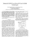
TCAD Driven CAD
A Journal for Process and Device Engineers
QUEST: Frequency-Dependent RLCG Extractor
Part 1 - Examples of Application
Introduction
Signals propagated in actual and future IC’s
interconnections are spreading, in terms of spectrum
frequency, from DC to microwave domain because of
the continually increasing clock frequencies of circuits.
So, predictions of impedance, delay, rise/fall times
and crosstalk levels need to be investigated within this
whole spectrum. QUEST is a powerful two-dimensional
extractor of the RLCG frequency dependent parameters
of the transmission lines. This tool is based on a fast
and accurate computation so-called “fictitious domain
method” [1]. In this article three examples of its use
are presented:
●
the variations of mutual/self inductance with the
geometrical parameters,
●
the crosstalk,
●
the skin effect.
The reader could compare these results with [2].
1. The Coupling Effects for Different
Geometries
The main structure considered in this example consists
of two metal wires (_ = 30 MS/m) separated from the
substrate by an oxide. The thickness of the oxide and
the spacing between the two wires are variables (see
Figures 1 and 2). The frequency has been fixed to 10 MHz.
Two values have been assigned to each variable, so that
QUEST would perform four simulations automatically.
Figure 1. Layout definition with parameterized spacing.
As outputs QUEST gives the four RLCG matrices. Table 1
summarizes the values of the inductances calculated
by QUEST.
Continued on page 2....
INSIDE
Session Oxide
number thickness
1
2
3
4
1
10
1
10
Spacing
(µm)
Mutual
inductance
(10-7 H/m)
Self
inductance
(10-7 H/m)
Non-Stationary Transport Effects: Impact on
Performances of Realistic 50nm
MOSFET Technology . . . . . . . . . . . . . . . . . . . . . . . . . 4
8
8
1
1
0.89
2.10
2.92
4.43
5.72
7.27
5.72
7.25
Modeling of Charge Distribution Using SchrodingerPoisson Equations: Application to Double-Gate
Transistor (i.e GAA-SOI Transistor) . . . . . . . . . . . . . . . 7
Table 1. Simulated values of inductances from QUEST.
Volume 12, Number 2, February 2002
Calendar of Events . . . . . . . . . . . . . . . . . . . . . . . . . . . . . 10
Hints, Tips, and Solutions . . . . . . . . . . . . . . . . . . . . . . . . 11
SILVACO
INTERNATIONAL
Figure 3 . Schematic diagram of the test circuit used to
examine crosstalk between two wires.
The further the line from the substrate, the bigger the
area of the loop and the higher the self-inductance. The
results of the mutual inductance show that the coupling
between the two lines increases when the spacing
decreases. Thus in VLSI technology, the lines most
prone to mutual induction are the lines far from the
substrate and close to each other.
Figure 2. DOE user-defined variation of pre-defined variables.
2. Crosstalk
The self-inductance increases with the oxide thickness,
but it is independent of the spacing between the lines.
Indeed the self-inductance characterizes the magnetic
energy stored in a closed conductor. This conductor is
not necessarily physically closed. In our example, a wire
and the substrate make a loop. Therefore, giving the
following formulas :
Neighboring wires are capacitively and inductively
coupled to each other, such that a transient signal on a
wire can have a significant effect on another
unconnected wire: this is the diaphony or crosstalk.
The previous example is used with a spacing equal to 1 µm
and an oxide thickness equal to 10 µm, so that coupling
effects are significant. The simulation is performed at
600 MHz, and the output RLCG matrix is used in
SmartSpice for a transient simulation.
ϕ = o∫ B.dS
ϕ
and L=–
Ι
with
B the magnetic field,
➞
➞
Figure 3 shows the circuit and figure 4 the result of the
transient simulation.
ϕ the magnetic flux,
I the current in the loop whose surface is S.
Figure 4. SmartSpice plot of node voltages illustrating
crosstalk between two wires.
The Simulation Standard
Figure 5. SmartSpice plot of node voltages illustarting enhanced
crosstalk with reduced rise and fall times.
Page 2
February 2002
Figure 6. Two-dimensional plot (left) and one-dimensional plot
(right) of current density inside two wires, one excited at 20 MHz.
Figure 7. Two-dimensional (left) and one-dimensional (right) plots of
current density inside two wires, one being excited at 20 GHz.
The skin effect is clearly evident.
E with σ=30 MS/m the conductivity of aluminum and
E=1V/m the applied electric field, J is the current density in A/cm2. One obtains J= 3000 A/cm2 uniformly in
the excited left wire. Figure 7 displays the same wires at
20 GHz, the current density is less than half the previous case and the current density is higher at the edges
of the conductor: this is the skin effect. At high frequency, the electromagnetic field is greatly attenuated inside
the conductor due to the inductive effect. This explains
the skin effect, but also this explains the proximity
effect : a current flow appears at the edge of the neighboring conductor. This is what one can observe in
Figure 7, in the right hand side wire.
The curve v(clk) is the clock signal (a pulse). The wire
between nodes 3 and 4 is the aggressor line and the
wire between nodes 1 and 2 is the victim line. At the
end of the aggressor line (node 4, v(4)), one observes
oscillations and voltage overshoot due to the self-inductance.
On the victim line, the crosstalk is obvious: a parasitic
signal propagates from node 1 (v(1) curve) to node
2 (v(2) curve), despite no bias being applied to the line.
It is also well known that the crosstalk increases as the
rise/fall times decreases. Figure 5 illustrates this case,
the rise time equals to 0.02 ns and the fall time 0.1 ns.
The crosstalk is much larger after the ramp-up bias than
after the ramp-down of the clock signal. This can be
explained by the higher frequency components of the
Fourier transform of the clock signal at the rise time
than at the fall time.
Conclusion
This article presented some examples of the electromagnetic behavior of two transmission lines: inductive
effects function of geometric variables, crosstalk and
skin effect. It shows that QUEST is a powerful tool dedicated to characterizing transmission lines for microelectronic design. QUEST gives a good solution to such
analyses that become more and more necessary as the
clock frequency and integration increase.
3. The Skin Effect
The skin effect can be observed at very high frequencies
and large conductors. Indeed the skin depth of aluminum at 1 GHz is 2.8 µm and so very close to the
cross-sectional dimensions of a wire. When the skin
effect appears the resistance of the line increases
because the current flows principally at the edge of the
conductor. For the simulation, two wires are defined,
spaced by 4 µm, their width is 5 µm, their thickness is 3
µm. Calculations are performed at 20 Mhz and 20 GHz.
Figure 6 shows the cross-section of the two wires and a
cutline was performed inside them. The current density
is displayed at 20 MHz. For this low frequency, the current density value can easily be calculated using :
References
[1] A Fast and Accurate Computation of Interconnect
Capacitance, S. Putot, F. Charlet, P. Witomski, IEDM 1999.
[2] High Frequency VLSI Interconnect Modeling, Dennis
Sylvester, http://www.device.eecs.berkeley.edu/~dennis/ee241/final.html
Part 2 - Comparison with Experiments will be published in the
Simulation Standard Volume 12, Number 2, May 2002 issue.
J = σ.
February 2002
Page 3
The Simulation Standard
Non-Stationary Transport Effects: Impact on Performances
of Realistic 50nm MOSFET Technology
D. Munteanu, G. Le Carval, G. Guegan
LETI, CEA / Grenoble, Microelectronics Department
17 rue des Martyrs, 38054 Grenoble, France
e-mail: [email protected]
Abstract
We analyze quantitatively the real impact of technology
on the needed level for carrier transport modeling. The
results, based on theoretical analyses, are applied to
existing devices. This work shows which recipes must
be used to evaluate the performances of advanced
device architectures (down to 50nm gate length). An
original point of this work is the investigation of technology
influence (channel doping and LDD doping) on injection
velocity at source side and on drain current. The results
open the perspective of specific engineering of access
regions in order to take full advantage of non-stationary
effects on the drain current.
1. Introduction
For MOSFETs with gate length ranging around and
below 0.1µm, it is now well established that the DriftDiffusion (DD) model fails to predict velocity overshoot
and carrier diffusion due to electronic temperature
gradients. Moreover, this model neglects the dependence
of hot-carrier effects on carrier energy, giving unphysical
results for issues related to impact ionization and
reliability. Hence, advanced models become mandatory
for accurate simulation of nowadays devices, even if
the question of the needed accuracy of modeling level
for practical applications still remains. Solutions like
Monte-Carlo (MC) simulation are very accurate [1], but
CPU-consuming, therefore difficult to be applied for
technology optimization. For this reason we preferred
to use an advanced energy transport model available in
commercial tools [2], which combines the advantages of
satisfactory accuracy and fast calculations.
Figure 1. Influence of energy relaxation time, τrel, on ID(VD) curves
(inset: variation of ratio IDsat(EB)/IDsat(DD) with τrel).
Consequently we have decided to use devices obtained
by simulating the technological process of our 50nm
technology [3]. Devices are designed with LDD extensions
and pockets, and the oxide thickness is 2.3nm. It was
demonstrated that DIBL is a major concern for an accurate
analysis of velocity overshoot [4], consequently we
optimized the shorter device (Lg=50nm) to have an Ioff
lower than 0.1nA/µm. Longer devices have the same
structure, which ensures low DIBL.
3. Calibration of Energy Balance Model
The simulations were performed with Drift-Diffusion
(DD) and a modified Energy Balance (EB) models of
ATLAS (Silvaco). The main parameters (mobility, carrier
statistics, recombination) are expressed by the same
models in EB and DD, with the difference that in EB
they are no longer electric field dependent, but carrier
energy dependent [2]. Compared to DD, EB considers
two additional equations: the conservation of the carrier
energy and the energy flux. A critical parameter in EB
model is the energy relaxation time, τrel, which governs
the magnitude of the non-stationary effects. Figure 1
shows that τrel has a strong impact on terminal currents.
The variation of IDsat (drain current at VG=VD=1.5V) versus
τrel is linear for τ rel between 0.05ps and 0.5ps, and
becomes saturated outside this range (inset in Figure 1).
After a short description of the simulated devices, we
calibrate the transport model on MC data. Then we
analyze how non-stationary effects impact the device
behavior and the dependence of this impact on main
technological parameters.
2. Simulated Devices
Many previous works are performed on simplified
devices (constant channel doping, no LDD, no pockets).
Since doping profiles strongly influence the spatial
variations of electric field, realistic devices are needed
for accurate conclusions on non-stationary effects.
The Simulation Standard
Page 4
February 2002
Figure 2. Profiles of velocity at 10Å channel depth obtained by
EB and DD at low and high drain voltage.
Figure 3. ID*Lg (VD) characteristics simulated with EB and DD
for different channel lengths.
When τrel decreases, carrier energy reaches equilibrium
with electric field faster, which implies less non-stationary
effects. Moreover, for τ rel <0.01ps the DD regime is
attained and the EB current is limited to the value predicted
by DD model. Since very controversial values of τrel
(from 0.1 to 1ps) are given in the literature, we calibrated
our simulator on MC data, the best match between EB
and MC results being obtained for τrel = 0.2ps.
IDsat(EB)/IDsat(DD) ratio is about 1.3 for Lg=50nm and
1.02 for Lg=0.25µm. The practical consequence of this
analysis is that we can evidence an inferior limit of the
channel length for using the classical DD model. In our
case this limit is about 0.25µm, therefore for shorter
gate lengths the use of advanced models is necessary
for obtaining accurate simulation results. We mention
that this limit can also slightly vary as a function of
gate-channel and source/drain-channel architecture.
Impact ionization is modeled by the Selberherr [2]
model in both DD and EB. In EB the effective field
depends on the carrier energy, through an energy relaxation
length related to τrel [2].
Figure 4 presents the variation of the EB electron velocity
along the channel for different Lg. An interesting result is
that the velocity overshoot at the drain side increases slowly
with Lg, while the opposite behavior was expected. The
explanation is that carriers are strongly accelerated in
short channels, but they cannot reach the maximum
velocity, as they are rapidly collected in the drain. When
Lg increases the maximum velocity increases and becomes
saturated for Lg=0.2µm. However, this phenomenon is
4. Simulation Results
4.1. Velocity Overshoot
The first effect of non-stationary transport in very short
channels is the velocity overshoot, which impacts directly
the drain current. The electric field-dependence in DD
model does not allow to simulate the velocity overshoot
phenomenon. This explains the difference between the
drain current obtained by EB and DD: (a) at high VD the
EB drain current is significantly higher, because in DD
model the velocity is limited to the saturation value
(about 107 cm/s, Figure 2), leading to under-estimated
drain current; (b) at low VD however, the velocity profiles
in the channel are almost the same for both models
(Figure 2), even in very short channels, which implies
the same drain current level.
It is worth noting that the difference between currents
predicted by EB and DD depends strongly on the channel
length, channel doping and LDD region doping. We
discuss in the following the impact of each parameter.
Channel length. When the channel length increases, the
difference between DD and EB decreases as shown in
Figure 3, and becomes negligible for L g >0.25µm.
February 2002
Figure 4. Profiles of velocity in the channel at 10Å depth for
various Lg (VG=VD=1.5V).
Page 5
The Simulation Standard
Figure 5. Drain and source–end velocity obtained by EB model
as a function of the channel length (VD=VG=1.5V).
Figure 6. Variation of ratio IDsat(EB)/IDsat(DD) and v(EB)/v(DD)
at source and drain end as a function of the gate length
(VD=VG=1.5V).
not reflected in the drain current because near the drain
the increase of the velocity with Lg is accompanied by a
strong decrease of the carrier concentration.
However, changes in doping imply V T variations,
which makes difficult the evaluation of the impact of
doping induced-velocity enhancement on ID. A first
order decorrelation of the two effects can be obtained
by taking into account the ratio I Dsat(EB)/I Dsat(DD).
Higher velocity is reflected by a more important
increase in the drain current, independent on doping
(Table 1). This result opens the perspective of specific
engineering of the access regions (LDD, pockets, channel
doping) to improve injection velocity, separately of VT
adjustments. This type of evaluation only begins to
appear in the literature [6].
Moreover, it has been shown that the current enhancement
is due to the increase in the velocity at the source side,
where the carrier concentration is gate controlled [5].
Indeed, Figure 5 shows that the source velocity increases
for shorter channels (because of a higher electric field at
the source end), which is reflected by a higher current.
The argument of source-side controlled current is also
confirmed by the current enhancement in EB compared
with DD (Figure 6). At the drain side the ratio between
velocity (v) in EB and DD is about 3.5 for Lg=50nm,
while the current increases only by 30%. This last value
is in good agreement with the ratio between velocities
in EB and DD at the source side. The same conclusions
are obtained for longer channels (Figure 6).
We have also verified the importance of using realistic
devices: simulations on simplified structures
overestimate the impact of non-stationary effects on the
terminal currents.
Finally, it is important to note that quantum effects will
have to be taken into account for a more accurate analysis
of the impact of velocity overshoot on drain current.
Channel/LDD doping. For lower channel doping or
higher LDD doping, the electric field at the source side
increases, which implies a higher velocity (Table 1).
Implanted Dose
vsource (_107cm/s)
IDsat(EB)/IDsat(DD)
(x1014cm-2)
Channel
(LDD dose:
0.8 x10¹⁴)
0.1
0.2
0.3
0.97
0.73
0.58
1.34
1.31
1.28
LDD
(Channel dose:
3 x10¹³)
0.5
1
2
0.54
0.78
1.14
1.22
1.33
1.45
Table 1. Impact of channel/LDD doping (L=50nm) on source velocity and drain current.
The Simulation Standard
Page 6
4.2. Impact Ionization
While the classical DD model can
be satisfactory for simulating channels longer than 0.25µm, impact
ionization needs an energy dependent-model even at much higher
lengths. The DD model depends
on electric field, which leads to a
strong over-estimation of impact
ionization for all channel lengths.
Continued on page 12...
February 2002
Modeling of Charge Distribution Using
Schrodinger-Poisson Equations:
Application to Double-Gate Transistor (i.e GAA-SOI Transistor).
I. Introduction
The Gate-All-Around SOI transistor [1], in which
the gate oxide and the gate electrode are wrapped
around the semiconductor region between the
source and drain electrodes, exhibits very attractive features [2,3]. This device has been shown to
present excellent Ion/Ioff trade-off, good threshold voltage roll-off reduction and better resisting
to short-channel effect and DIBL. In this study,
based on the self-consistent solution of
Schrodinger and Poisson equations, we attempt to
show that the maximum of electrons concentration can be located in the middle of the semiconductor film and that it exist an "optimal" thickness
of the Si-film. This is a major divergence with classical models which predict always the maximum
of electron concentration at the semiconductor
interface and that the reduction of the film thickness is always better against parasitic effects.
II. Device Structure
Figure 1. GAA-SOI device structure.
The GAA-SOI was built in ATLAS. In this work
symmetrical gate-SiO2-Si(p)-SiO2-gate structure
with uniformly doped substrate is considered (Figure
1). The main characteristics are: fixed gate oxide thickness of 25nm, variable Silicon film thickness from 1.5nm
to 20nm and uniform p-type doping of 1e18 cm-3.
III. Schrodinger Calculation in ATLAS
The self-consistent Schrodinger-Poisson model is
enabled by setting the SCHRO parameter of the model
statement. With this parameter set ATLAS solves the
one dimensional Schrodinger’s equation along a series
of slices in the y direction relative to the device. Each
slice is taken along an existing set of y nodes in the
ATLAS device mesh. After the Schrodinger’s equation
solution is taken, carrier concentration calculated from
Schrodinger’s equation are substituted into the charge
part of the Poisson’s equation. The potential derived
from solution of Poisson’s equation is substituted back
to Schrodinger’s equation. This solution process
(alternating between Schrodinger’s and Poisson’s equation)
is continued until convergence is reached and a
self-consistent solution of Schrodinger’s and Poisson’s
equation is obtained. For more details see [4].
IV. Results and Discussion
Figure 2. Spacial distribution of electrons concentration using
"classical" or Schrodinger" calculation.
February 2002
Page 7
Figure 2 presents spatial distributions of electrons
concentration. The fundamental difference between the
classical and Schrodinger calculation lies in the fact that
the maximun of electrons concentration is localized at
the semiconductor interface for classical calculation
whereas it is localized inside the semiconductor film
using Schrodinger-Poisson calculation.
The Simulation Standard
Figure 3. Conduction Band and discrete Energy Levels in the
semiconductor film.
Figure 4. Conduction Band and discrete Energy Levels in the
semiconductor film. Note the two subwells for the lowest Energy
Level E1.
Moreover, the quantization of electron energy in the
double gate SOI structure depends on the film
thickness. At very thin semiconductor films, the energy
quantization results mainly from the confinement of
electrons in the semicondcutor. Then the discrete
energy level can be expressed by the rectangular well
approximation.
To be able to simulate these effects, the 2D Electron Gaz
has to be described by the self-consistent resolution of
Schrodinger and Poisson equations.
For the reason explained abve, one interesting point is
that if the semiconductor film is thin enough, the
maximum of electron concentration can be located in
the middle of it (Figure 5), supporting the concept of
volume inversion [2]. Again the classical theory gives
the electron concentration always maximum at the
semiconductor surface.
At larger semiconductor film thickness two additional
potential subwells are created at both surfaces which
can confined the lowest electron states E1 (Figure 4).
On top of that, one can observed that the maximum
charge density increases and then decreases as a
function of Tsi [5]. Figure 6 and 7 illustrate and explain
this aspect. In Figure 6 it is sown that for the thinnest
thicknesses, the charge appears to be mainly controlled
by the lowest Energy level. Indeed Energy Levels below
the Fermi Level are full of electrons whereas Energy
Levels above the Fermi Level are empty. E2 in Figure 6
for Tsi=1.5nm is located above the Fermi level and thus
empty of electrons.
However, due to the confiment, the distance between
the first Energy level and the Fermi level increases
when the film thickness decreases, which conducts to
a decrease of the charge for a film thickness below
5nm (Figure 7).
We have quantify the total number of electrons in the
channel using one of the powerful features of the
extract routine available in deckbuild. The key word to
use to do that in the EXTRACT statement is 2D.AREA,
F i g u r e 5 . I n f l u e n c e o f S i l i c o n f i l m t h i c k n e s s o n e l e c t r o n which allow to perfrom double integral of any
concentration distribution.
quantities present in the structure file. Refer to [6] for
The Simulation Standard
Page 8
February 2002
V. CONCLUSION
As a conclusion we have demonstrated in this
article the importance of the use of SchrodingerPoisson calculation to evaluate performance of
novel devices like Double Gate Transistor (i.e
GAA-SOI Transistor) where the dimension (Si
film thickness) are very small and thus leads to
confinement and quantization. Based on this
study we have shown that the optimization of
performance of such devices will not be achieved
by only reducing the thickness of the film (as
predicted by the classical approach) but that it
exist on optimum of Si-film thickness that can
potentially conduct to better performance.
References
[1] J.P. Colinge et al. IEDM (1990) p. 595
[2] F. Balestra et al. IEEE Electron Device Lett. 8, 410
(1987)
[3] B. Majkusiak et al. IEEE Trans. Electron Devices 45,
1127 (1998)
[4] “ATLAS User’s Manual- Vol 1” p. 3-85
Figure 6. Discrete energy Levels(E1 ‡ E3) as a function of Si film thickness.
[5] S.Monfray et al. ESSDERC (2000) p. 336
[6] “Interactive Tools User’s Manual”- Vol 1 p. 5-16
more details. We show that it exists an "optimal" Si-film
thickness (Figure 7), for which the total number of
electrons is maximum. For
Na=1e18 this is verified for
Tsi=3.5nm.
As a consequence this result has a
direct impact on the design of GAASOI Transistor or more generally
Double Gate Transistor since it has
been demonstrated that it exist an
optimized film thickness leading to a
maximum of electrons concentration.
The idea that consist of reducing the
film thickness to obtain better
performance seems no more valid in
this case. We have investigated the
influence of doping of the Si-Film
and it appears that the "optimized"
thickness increases when the doping
level in the film decreases (Figure 9).
Indeed an "optimized" film thickness
is around 7nm for Na=1e17.
Figure 7. First Discrete Energy Levels in the semiconductor film as a function of Si
film thickness.
February 2002
Page 9
The Simulation Standard
Calendar of Events
February
1 TCAD W/S- Scottsdale, AZ
EDS Techno Fair-Yokohama
ASP DAC - Yokohama,Japan
2 EDS Techno Fair-Yokohama
ASP DAC - Yokohama,Japan
3
4
5
6
7
8
9
10
11
12
13 Int’l Conf. on Microelectronics
and Interface - Santa Clara, CA
14 Int’l Conf. on Microelectronics
and Interface - Santa Clara, CA
15 Expert W/S - Scottsdale, AZ
16
17
18
19
20
21 TCAD W/S - Chelmsford, MA
Int’l Forum On Semicon Tech Yokohama - Japan
22 Int’l Forum On Semicon Tech Yokohama - Japan
23
24
25 Compound Semiconductor
Outlook - San Mateo, CA
26 Compound Semiconductor
Outlook - San Mateo, CA
27 Compound Semiconductor
Outlook - San Mateo, CA
28
March
1
2
3
4
5
6
Bulletin Board
CLEVER W/S - Scottsdale, AZ
DATE - Paris, France
DATE - Paris, France
TCAD W/S-Cambridge University
DATE - Paris, France
7 DATE - Paris, France
8 DATE - Paris, France
9
10
11 GOMAC - Monterey, CA
12 TCAD /CAD W/S- Fairfax, VA
TCAD W/S-Cambridge University
GOMAC - Monterey, CA
13 GOMAC - Monterey, CA
14 GOMAC - Monterey, CA
15 ATLAS W/S - Scottsdale, AZ
16
17
18
19
20 Int’l Conf. for Microelectronic
Test Structures - Cork, Ireland
21 Int’l Conf. for Microelectronic
Test Structures - Cork, Ireland
22 Int’l Conf. for Microelectronic
Test Structures - Cork, Ireland
23
24
25
26
27
28 Japan Applied Physics Aoyama Gakuin University
29 Japan Applied Physics Aoyama Gakuin University
30 Japan Applied Physics Aoyama Gakuin University
31 Japan Applied Physics Aoyama Gakuin University
Silvaco Wins Judgement Against
Avant! Again
In July 2001 the Appeals Court remanded a 1997
judgement of $31.4 million to the Superior Court
to fix a number of small mistakes. The crown
jewel of the original 1997 judgement, the $20
million default award, was preserved intact. The
prove-up hearing for this default was held
February 6th, 2002 before Superior Court Judge
Jack Komar. After hearing the evidence Judge
Komar awarded Silvaco the $20 million default
judgement (plus $6.148 million in interest.)
TCAD Simulation Workshops
Silvaco is delighted to announce a workshop program at Cambridge University. The one-day workshop is intended for users of Silvaco's TCAD
Process and Device Simulation software suite. It will
be hosted at Cambridge University on the March 6,
2002 and repeated on March 12, 2002. The workshop is free of charge to customers taking advantage
of our support package. For more info contact:
[email protected]
Silvaco Signs Everest as
New Digital Partner
Everest Design Solutions, LLC today announced
a partnership with Silvaco International as it’s
exclusive EDA tools distributor. Silvaco is both
pleased and eager to begin selling the complete
Everest line to customers seeking quality digital
solutions. This partnership will allow Everest to
draw on Silvaco’s established global presence
while providing Silvaco with a strong entry into
the digital design space of the EDA market.
For more information on Everest Design Solutions
visit our web site at:
www.best.com/~eds.
If you would like more information or to register for one of our our workshops, please check our web site at http://www.silvaco.com
The Simulation Standard, circulation 18,000 Vol. 12, No. 2, February 2002 is copyrighted by Silvaco International. If you, or someone you know wants a subscription to this free publication, please call (408) 567-1000 (USA), (44) (1483) 401-800 (UK), (81)(45) 820-3000 (Japan), or your nearest Silvaco distributor.
Simulation Standard, TCAD Driven CAD, Virtual Wafer Fab, Analog Alliance, Legacy, ATHENA, ATLAS, MERCURY, VICTORY, VYPER, ANALOG EXPRESS,
RESILIENCE, DISCOVERY, CELEBRITY, Manufacturing Tools, Automation Tools, Interactive Tools, TonyPlot, TonyPlot3D, DeckBuild, DevEdit, DevEdit3D,
Interpreter, ATHENA Interpreter, ATLAS Interpreter, Circuit Optimizer, MaskViews, PSTATS, SSuprem3, SSuprem4, Elite, Optolith, Flash, Silicides, MC
Depo/Etch, MC Implant, S-Pisces, Blaze/Blaze3D, Device3D, TFT2D/3D, Ferro, SiGe, SiC, Laser, VCSELS, Quantum2D/3D, Luminous2D/3D, Giga2D/3D,
MixedMode2D/3D, FastBlaze, FastLargeSignal, FastMixedMode, FastGiga, FastNoise, Mocasim, Spirt, Beacon, Frontier, Clarity, Zenith, Vision, Radiant,
TwinSim, , UTMOST, UTMOST II, UTMOST III, UTMOST IV, PROMOST, SPAYN, UTMOST IV Measure, UTMOST IV Fit, UTMOST IV Spice Modeling,
SmartStats, SDDL, SmartSpice, FastSpice, Twister, Blast, MixSim, SmartLib, TestChip, Promost-Rel, RelStats, RelLib, Harm, Ranger, Ranger3D Nomad, QUEST,
EXACT, CLEVER, STELLAR, HIPEX-net, HIPEX-r, HIPEX-c, HIPEX-rc, HIPEX-crc, EM, Power, IR, SI, Timing, SN, Clock, Scholar, Expert, Savage, Scout,
Dragon, Maverick, Guardian, Envoy, LISA, ExpertViews and SFLM are trademarks of Silvaco International.
The Simulation Standard
Page 10
February 2002
Hints, Tips and Solutions
William French, Applications and Support Manager
Q. How do I install and use my Silvaco TCAD tools on
a Windows 2000 machine ?
Q. After installing the tools in the prescribed manner
how do I know if I was successful ?
A. Silvaco software supports licensing on Windows NT
(Serverice Pack 4. or later) and Windows 2000 Pro. As a
new user you should receive 3 components before you
can begin to run the software.
A. Bring up the system Task Manager (Ctrl-Alt-Del and
then choose Task Manager), show all processes that are
running and look for one called rpc.sflmserverd that
should be running. If this is not in the list, perform the
operation:
●
●
●
the Silvaco software itself
a security key (also called a dongle)
a license file (sent via email from Silvaco HQ)
All three of these are necessary before you can run
the software.
NOTE: Silvaco license server requires the existence of
the folder c:\Temp in order to store temporary files. If
this folder does not exist the software will not work.
Step 1.
Insert the dongle into either the parallel port or the USB
port. Both are supported by Silvaco, but are different
keys. The one you receive is decided at time of
purchasing the software.
Start-->Programs-->Silvaco--Sflm-->Start Server
Note: If Start Server option is not there then you failed
to click the License option suggested in Step 2. Remove
the installation and repeat.
Q. How do I know what licenses are available or who
has checked out licenses ?
A. The installation creates a Shortcuts folder on the PC
Desktop. Double-clicking on this icon will cause a pop-up
to appear with the application Shortcuts. Two of these
are labelled "Server status" and "Current users". If the
user double-clicks on these icons a DOS window
should appear that shows all available licenses and
which users have checked out particular licenses,
respectively.
Step 2.
Install the software from either the CDROM or the FTP
downloaded file. This is started by executing the Setup
utility. Normal installations should follow the defaulted
choice for each window. This will be either Next or Yes.
Note: When choosing products to install make sure that
the LICENSING option has been checked.
Q. I have obtained a new license file what should I do ?
A. To activate the new license file, simply copy it to the
folder c:\Silvaco\etc where the software was installed.
Then rename this file to simply "license" and reboot the PC.
Note: Make sure that there is no extension on the file. If
the file is called for instance license.dat then the license
manager will not start.
Step 3.
During the software installation you will be asked to
navigate to the license file that you received from
Silvaco. Make sure this is available on your machine.
Step 4.
Restarting the Windows operating system is necessary
in order to enable communication between the software
and the dongle. This is normally recommended.
February 2002
Q. I have been running the software successfully, but
suddenly nothing will work. What should I do ?
A. A number of different actions may have caused this
to occur. Below are some common reasons.
●
Page 11
the license file has expired. Certain Silvaco licenses
are for a fixed duration. Open the license file inside
Wordpad and look for the lines entitled END_DATE.
If any exist that are past then your license has
expired and you should contact your Silvaco representative or email [email protected] with a copy
of your license file.
The Simulation Standard
●
●
the date or time on the machine may have been
modified. If the system clock is more than one hour
out of sync with local time, correct the machine time,
delete the folder c:\Temp\.sflm and reboot the PC
Q. Is there any documetation available to help in troubleshooting installation problems ?
A. After the software is installed, the user can find an
extensive list of troubleshooting tips in the file entitled
FAQ which resides in the Shortcuts folder as well as in
c:\Silvaco\var\FAQ.txt
the dongle may have been damaged. To check this
run the following command from the DOS prompt
c:\Silvaco\bin\showid.exe -time
the output from this should be self explanatory. This
will also display the machine name and HASP number.
The machine name should be repeated in the file
c:\Silvaco\var\sflmserver and the HASP number
should be the same as the line in the license file that
starts with LM_HOSTIDS.
Call for Questions
If you have hints, tips, solutions or questions to contribute, please
contact our Applications and Support Department
Phone: (408) 567-1000
Fax: (408) 496-6080
e-mail: [email protected]
Hints, Tips and Solutions Archive
Check our our Web Page to see more details of this example
plus an archive of previous Hints, Tips, and Solutions
www.silvaco.com
If these are not sufficient to correct the problem contact
[email protected].
...continued from page 6
Figure 7 presents ID(VD) curves for short and long channels,
illustrating the over-estimation of the avalanche region
by the DD model. Therefore EB model must be used for
impact ionization at all channel lengths. Accurate simulation of impact ionization is a very important issue for
simulating substrate current and hot carrier effects in
bulk devices. This is also a critical point for reproducing
accurate I D(V D) curves and kink region in partially
depleted SOI devices [7].
5. Conclusion
In this paper we have presented the impact of the
modeling level on the electrical behavior of 50nm bulk
MOSFET technology. For accurate conclusions, realistic
devices have been considered in simulation. The current enhancement due to non-stationary effects must
always be referred to the velocity at the source side of
the device, and not to drain side. For reproducing the
impact of velocity overshoot advanced models are necessary for channel lengths below 0.25µm, while for
impact ionization an energy dependent model must be
considered even for much higher dimensions. An original analysis in this work is the quantitative evaluation
of technological parameters impact on injection velocity
and drain current. The results show that for taking full
advantage of non-stationary effects on device
performances specific engineering of access regions
have to be envisaged.
The Simulation Standard
Figure 7. ID(VD) curves obtained by EB and DD with impact
ionization model at different Lg.
6. References
[1]. M. Fischetti, S. Laux, Phys. Rev.B, no.14, p.9721, 1988.
[2]. “ATLAS Users Manual”, Silvaco.
[3]. C. Caillat et al., 1999 VLSI Tech. Dig., p. 89-90.
[4]. C. Jungeman et al., Proceedings ESSDERC 1999, p. 236.
[5]. G. Baccarani et al., Solid State Electronics, vol. 28, no.4,
p. 407, 1985.
[6]. S. Odanaka, A. Hiroki, IEEE Trans. on Electron Dev., vol.
44, no. 4, p. 595, 1997.
[7]. D. Munteanu et al., Proceedings of International SOI
Conference, p. 58-59, 2000.
Page 12
February 2002
Your Investment in Silvaco is
SOLID as a Rock!!
While others faltered, Silvaco stood SOLID for
15 years. Silvaco is NOT for sale and will
remain fiercely independent. Don’t lose sleep,
as your investment and
partnership with Silvaco will only grow.
SILVACO
CONTACTS:
I N T E R N AT I O N A L
Silvaco Japan
[email protected]
USA HEADQUARTERS
Silvaco Korea
[email protected]
Silvaco International
4701 Patrick Henry Drive
Building 2
Santa Clara, CA 95054
USA
Phone:
Fax:
408-567-1000
408-496-6080
[email protected]
www.silvaco.com
Silvaco Taiwan
[email protected]
Silvaco Singapore
[email protected]
Silvaco UK
[email protected]
Silvaco France
[email protected]
Silvaco Germany
[email protected]
Products Licensed through Silvaco or e*ECAD
Ve n d o r P a r t n e r