1
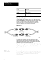
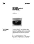
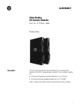
Product Data Perterminated FiberOptic Cables and Splice Connector Preterminated FiberOptic Cables and Splice Connector (Cat. No 1771-PT1, -PT2, -PT3, -PT4, -CPR) Product Data Introduction This data sheet describes: the fiber-optic cables available from Allen-Bradley how to install the cables in a PLC-2 and PLC-3 system Cable Description Indoor-rated duplex fiber-optic cables are available from Allen-Bradley in four (4) lengths. You use these preterminated and pretested cables to interconnect 1771-AF fiber-optic converter modules into a complete fiber-optic link. The following table lists these cable assemblies and their catalog numbers: 1 Product Dta Preterminated FiberOptic Cables and Splice Connector Cat. No. Cable Length 1771PT1 30 Meters (98 Feet) 1771PT2 75 Meters (246 Feet) 1771PT3 150 Meters (492 Feet) 1771PT4 300 Meters (984 Feet) Splice Connector Decription The Allen-Bradley Splice Connector, (cat. no. 1771-CPR), allows you to connect (at maximum) two preterminated fiberoptic cables together. Refer to figure 1. You must use two (2) splice connectors for each duplex fiber-optic cable splice. You can calculate the dB loss of each splice connector by adding the losses of both cable terminations. Figure 1 Splice Connector To install the splice connector, simply screw the SMA-style cable connectors into the splice connector until seated. Hold the cable body while tightening the connector. Be sure you do not kink the cable during installation in order to avoid cracking the fiber core. Important: Exercise special care in calculating the dB loss budget when using splice connectors. These connectors increase the fiber-optic link’s dB losses. Refer to the Fiber-Optic Converter Module User’s Manual, publication 1771-6.5.36. Cable Location 2 You can route fiber cables in the same conduits and wireways that contain conventional wiring. Consult the current edition of the National Electrical Code. Article 770 covers the installation of fiber-optic cables with electrical conductors. Product Data Perterminated FiberOptic Cables and Splice Connector Fiber cables are dielectric. They are non-conductive and are not affected by electromagnetic signals emitted from conventional wire cables. Below are some general physical installation guidelines to follow: Do not install the cable where objects may drop and crush it. Place underground-rated cable in polyethylene or PVC conduit if the installation is underground. Be sure the inside diameter of the pipe is at least four times larger than the outside diameter of the cable. Be sure aerial-rated cable can support its own weight and any additional weight imposed by wind, ice, or snow. Use a messenger cable if necessary. Follow the manufacturer’s hanging guidelines. Secure the cable every six feet (minimum) during long vertical runs. The clamp bushings should be constructed of a soft material, such as plastic or rubber. Cable in Ducts Observe the following guidelines when you install fiber cable in ventilation ducts: Do not place fiber cables in ventilation ducts unless the cables are plenum-rated. Be sure there are no sharp edges in any ductwork that could cut the cable. Be sure that other heavy wire cables in the ducts do not exceed the maximum crush resistance of the fiber. Cable in Conduit The following guidelines apply when you install fiber cables in conduit: Be sure bends in the conduit do not cause the fiber cable to exceed its minimum bend radius. Use corner elbow fittings for right-angle bends, such as Crouse-Hinds elbows (type BUB) of the Mogul series or equivalent. These fittings reduce the amount of stress applied to the fiber when pulling cable. Be sure the cable does not kink as you pull it. CAUTION: Do not pull a fiber cable that contains a splice connector through conduit. The splice connector will separate during installation. Cables that contain a splice connector are intended solely for “lay-in” wire tray installation and repairs. 3 Product Dta Preterminated FiberOptic Cables and Splice Connector Place pull boxes every 200-300 feet to reduce the amount of cable that needs to be pulled at any one time. Use pull boxes if the conduit makes several bends which total more than 180°. Pull box openings should be at least four times the minimum bend radius of the cable. Refer to the current edition of the National Electrical Code for the appropriate article covering cable installation in conduit. Cable Pulling Guidelines Pulling fiber cable is similar to pulling conventional copper wire cable. There are two factors, however, which you must consider: fiber-optic tensile strength and minimum bend radius. Fiber cable has a lower tensile strength than copper wire cable of the same outer diameter (i.e. you cannot exert the same pulling force on a fiber cable as you can on a copper wire cable). Too much fiber cable stretching can cause increased attenuation. You can also cause the fiber-optic connectors to separate from the cable. CAUTION: A fiber-optic splice connector is designed to optically connect two fiber-optic cables. The connector cannot withstand the tensile load of a cable “pull in” installation. Do not install a fiber-optic cable that contains a splice the way you would a one-piece cable. Spliced cables are intended solely for “lay-in” installation. The fiber cable’s minimum bend radius is the smallest radius the cable can accommodate without being damaged. Straining a cable beyond its minimum bend radius may permanently damage it. 4 Product Data Perterminated FiberOptic Cables and Splice Connector To reliably pull a pre-terminated fiber cable, you must attach the cable to a pulling device that protects the fiber-optic connectors. Refer to figure 2. Use the following procedure: Figure 2 Typical Preterminated FiberOptic Cable Pulling Grip Kellems Fiber-Optic Pulling Grip Harvey Hubbel Inc. Kellems Division Route 1, Lords Hill Stonington, CT 06278 203-535-1250 1. Place the cable in the braided portion of the pulling device, either a Kellems Fiber-Optic Pull Grip or equivalent. Leave the cable connectors and approximately four to six (4-6) inches of cable extending beyond the braid. 2. Using the attached needle and cord, enclose the cable with the braid by lacing it. 3. Wrap the cable connectors with foam packing material or equivalent. Leave the dust cover caps on the cable connectors. 4. Position a piece of heat-strink tubing over the connectors. Heat the tubing with a hot-air gun. 5. Using electrical tape and beginning at the base, spirally overwrap the pull grip where the fiber cable connectors protrude. Be sure you cover the fiber-optic connectors completely. 6. Lubricate the cable with conventional cable lubricant. 7. Monitor the cable tensile force while pulling the cable. 5 Product Dta Preterminated FiberOptic Cables and Splice Connector Connecting Cables to the FiberOptic Module 8. When the cable enters a pull box at an angle, use at least a 12-inch pulley if the cable is under tension. If the cable is not under tension, use at least a four-inch pulley. 9. As you pull cable from a pull box, coil it in a figure-eight with one-foot loops. This helps prevent the cable from twisting as you continue pulling. To connect the fiber-optic cables to the 1771-AF module, refer to figures 3 and 4. Use the following procedure: Remove the dust cover caps from the module’s fiber ports. (Do not discard the dust cover caps. They are required for module storage and shipment.) Remove the dust covers from the ends of the cable. (Do not discard the cable dust cover caps.) Important: Do not scratch the ends of the cable by touching them or dropping them on hard surfaces. Also, do not use factory compressed air to clean the transmitter/receiver ports. Contaminants in the air can scratch or cloud the ports. Attach the cable to the modules by screwing the cable connectors onto the appropriate fiber port. Hold the cable body while tightening the connector. Be sure you do not kink the cable during installation so the fiber core does not crack. Note that during installation you must criss-cross one end of the fiber cable leads as shown in figures 3 and 4. WARNING: Never look into the ends of an active fiber-optic cable or the fiber-optic module transmitters. Harmful optical radiation may be present. Permanent eye damage could result. Use a fiber-optic power meter to determine if a signal is present. 6 Product Data Perterminated FiberOptic Cables and Splice Connector Figure 3 Typical PLC2 FiberOptic Installation Figure 4 Typical PLC3 FiberOptic Installation 7 Product Dta Preterminated FiberOptic Cables and Splice Connector FiberOptic Cable Loss Test This test allows you to measure the amount of optical loss in the cable. To test preterminated cables you will need an optical power source and power meter along with a fiber-optic test cable. (Refer to figure 5.) Figure 5 FiberOptic Cable Loss Test Use this procedure to test the cable: 1. Attach one end of the test cable to the fiber-optic power source. WARNING: Never look into the ends of an active fiber-optic cable or the fiber-optic module transmitters. Harmful optical radiation may be present. Permament eye damage could result. Use a fiber-optic power meter to determine if a signal is present. 8 2. Attach the other end of the test cable to the optical power meter. 3. Adjust the source power until the optical power meter registers 0 dBu. 4. Turn the fiber-optic source off. 5. Disconnect the test cable from the optical power meter. 6. Use a fiber-optic splice connector to connect one end of the preterminated cable to the test cable. 7. Connect the other end of the preterminated cable to the optical power meter. 8. Turn the fiber-optic source on and read the optical power in dBu. This value is the optical loss of the cable. 9. Turn the fiber optic source off. Product Data Perterminated FiberOptic Cables and Splice Connector 10. Repeat steps 5 through 8 for the preterminated cable’s other fiber. Both fibers must have low loss connections for proper fiber-optic communication. If the cable loss is higher than expected, the cause may be a break in the cable or a lossy connection. Related Publications For additional information on Allen-Bradley’s fiber-optic products, refer to the following publications: Fiber-Optic Converter Module Product Data Sheet Publication 1771-2.90 Fiber-Optic Converter Module User’s Manual Publication 1771-6.5.36 Specifications Core Diameter G 100∝m Cladding Diameter G 140∝m Number of Fibers G 2 Termination Connector Style G SMA905 ScrewType Strength Member G Kevlar Bandwidth @ 850nm G 100 MHzKm Numerical Aperture (NA) G 0.29 Jacket Material G PVC Cable Configuration G Tight Buffer Outside Cable Diameter G 4 x 7 mm (0.157 x 0.275 in) Weight G 26.5 Kg/Km (17.7 lbs/1,000 ft) Installation Tensile Load G 1000 N (224.8 lbs) Tensile Load G 300 N (67.4 lbs) Minimum Bend Radius (No Load) G 3 Cm (1.182 in) Crush Resistance G 220 N/Cm (250 Ibs/ft) Impact Resistance G 2.5 N/M (1.845 ft/lbs) Storage Temperature G 40 to +80° C (40 to + 176° F) Operating Temperature G 20 to +70°C (4 to + 158° F) Flex and Twist Resistance (5 cm Radius) G 2000 Cycles Attenuation @ 850nm G 5 dB/Km 1986 Allen-Bradkey Company PLC is a registered trademark of Allen-Bradkey Company 9 Product Dta Preterminated FiberOptic Cables and Splice Connector With offices in major cities worldwide WORLD HEADQUARTERS Allen-Bradley 1201 South Second Street Milwaukee, WI 53204 USA Tel: (1) 414 382-2000 Telex: 43 11 016 FAX: (1) 414 382-4444 EUROPE/MIDDLE EAST/AFRICA HEADQUARTERS Allen-Bradley Europe B.V. Amsterdamseweg 15 1422 AC Uithoorn The Netherlands Tel: (31) 2975/43500 Telex: (844) 18042 FAX: (31) 2975/60222 Publication 1771–2.94 — August, 1986 As a subsidiary of Rockwell International, one of the world’s largest technology companies — Allen-Bradley meets today’s challenges of industrial automation with over 85 years of practical plant-floor experience. More than 11,000 employees throughout the world design, manufacture and apply a wide range of control and automation products and supporting services to help our customers continuously improve quality, productivity and time to market. These products and services not only control individual machines but integrate the manufacturing process, while providing access to vital plant floor data that can be used to support decision-making throughout the enterprise. ASIA/PACIFIC HEADQUARTERS Allen-Bradley (Hong Kong) Limited Room 1006, Block B, Sea View Estate 28 Watson Road Hong Kong Tel: (852) 887-4788 Telex: (780) 64347 FAX: (852) 510-9436 CANADA HEADQUARTERS Allen-Bradley Canada Limited 135 Dundas Street Cambridge, Ontario N1R 5X1 Canada Tel: (1) 519 623-1810 FAX: (1) 519 623-8930 LATIN AMERICA HEADQUARTERS Allen-Bradley 1201 South Second Street Milwaukee, WI 53204 USA Tel: (1) 414 382-2000 Telex: 43 11 016 FAX: (1) 414 382-2400 PN 955099–08 Printed in USA 10