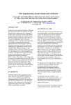
1
User Manual
Operating Manual
NOTE
This manual describes the installation and operation of Quick Ray Master UATM-272.
Review this manual to avoid injury and prevent damage to this product or any products connected to it before
you operate this instrument. To avoid potential hazards, use this product only as specified in this manual.
This documentation contains information and warnings that must be followed by the user to ensure safe
operation and to maintain the product in a safe condition.
Customer shall be responsible for paying all shipping charges, duties, taxies, and any other charges for any
failure or damage or injury caused by improper use or improper or inadequate maintenance and care. Unitma
Co., Ltd. shall not be obligated to furnish service under this case a) to repair damage resulting from attempts by
personnel other than Unitma Co., Ltd. representatives to install, repair or service the product; b) to repair damage
resulting from improper use or connection to incompatible equipment; c) to repair any damage or malfunction
caused by the use of non-Unitma Co., Ltd. supplies; or d) to service a product that has been modified or
integrated with other products when the effect of such modification or integration increases the time or difficulty of
servicing the product.
Copyright© Unitma Co., Ltd. All rights reserved. Licensed products are owned by Unitma Co., Ltd., and are
protected by national copyright laws and international treaty provisions. Unitma Co., Ltd products are covered by
patents, issued and pending. Specifications and price change privileges reserved.
Quick Ray is registered trademarks of Unitma Co., Ltd.
All Information is subject to change without prior notice.
Contacting Unitma Co., Ltd.
UNITMA Co., Ltd. 3F, Chungmyeong B/D, 224-8,
Jamsil-Dong, Songpa-Ku, Seoul, 138-220, Korea
Tel:
+82-2-420-0070
Fax:
+82-2-420-9797
http://www.unitma.com
E-mail: [email protected]
2
Operating Manual
Table of contents
1. IMPORTANT NOTES
1.1. Explanation of Symbols used
1.2. Name plate
1.3. Qualification of personnel
1.4. Intended use of instrument
2. SAFETY NOTES
3. INSTRUMENT COMPONENTS AND SPECIFICATIONS
3.1. Instrument description
3.2. Instrument component
3.3. Instrument specification
3.4. Consumable (Recipient block)
4. SETUP
4.1. Installation site requirements
4.2. Setup
4.3. Connecting to main power supply
4.4. Turning on / off the instrument
5. GENERAL PROCEDURE OF TISSUE MICROARRAY
5.1. Building TMA with Quick Ray Master
5.2. Preparation for punching and inserting with Quick Ray Master
5.3. Procedures for punching and inserting with Quick Ray Master
5.4. Auto run Operation
5.5. Manual Operation
5.6. Set Mode for Calibration
5.7. Miscellaneous Buttons
5.8. Report
5.9. Alarm sound
5.10. Help
5.11. Demo
6. CLEANING & MAINTENANCE
6.1. Cleaning the instrument
3
Operating Manual
6.2. Replacing consumable
6.3. Replacing components
6.4. Maintenance
6.5. Repair
6.6. Disposal of waste
7. TROUBLE SHOOTING
7.1. Instrument failures
7.2. Operating errors with possible causes and corrective action
8. WARRANTY & SERVICE
4
Operating Manual
1. IMPORTANT NOTES
1.1.
Explanation of Symbols used
WARNING: WARNING indicates an injury hazard not immediately accessible
as you read this symbol. It calls attention to an operating procedure, practice,
or the like, that if no correctly performed or adhered to, could result in
personal injury or death. Do not proceed beyond a WARNING notice until the
indicated conditions are fully understood and met.
CAUTION: CAUTION indicates a hazard not immediately accessible as you
read this symbol. It calls attention to an operating procedure, practice, or the
like, that if not correctly performed or adhered to, could result in damage to
the product or loss of important data. Do not proceed beyond a CAUTION
notice until the indicated conditions are fully understood and met.
Protective Ground or Earth Terminal. Used to indicate a circuit common
connected to grounded chassis.
Main Power Connected or ON
Main Power Not Connected or OFF
(Pushed) : PC POWER on
(Pulled) : PC POWER off
BIOHAZARD WARNING: BIOHAZARD WARNING indicates an injury or hazard
not immediately accessible as you read this symbol.
Bio-hazard (Infectious agent): A type of micro-organism, bacteria, mold,
parasite or virus which normally causes, or significantly contributes to the cause
of, increased morbidity or mortality of human beings.
5
Operating Manual
1.2. Name plate
The name plate of UATM-272 is at the
right side of UATM-272. The name plate
indicates the serial number, year of
manufacture, and the power rating and
frequency.
1.3. Qualification of personnel
The Quick Ray Master UATM-272 should be operated by trained “Histopathology
laboratory” personnel.
All laboratory personnel designated to operate UATM-272 is required to read this
entire manual before operating UATM-272.
1.4. Intended use of instrument
The Quick Ray Master UATM-272 is an automated Tissue Microarrayer for extracting the tissues
from donor blocks and subsequently delivering into recipient blocks.
1) The user inserts donor blocks and a recipient block into the block stage, and puts the block
stage into the stage holder. (Donor blocks should be made from "paraffin embedded tissues" and
recipient block should be just only UB06 supplied and made by UNITMA Co., Ltd.)
2) The user will see images of donor blocks and recipient blocks on a built-in LCD monitor, and
can use the touch screen to adjust settings and run the UATM-272. Users can select and save
the specific position for extraction of tissue core on the selected donor block image and the
specific hole of corresponding recipient block by clicking the block image and button image of the
touch screen.
3) When the user clicks the 'RUN' button in software program for the TMA procedure, UATM-272
executes the TMA block construction process as programmed by the user.
4) The user can print the TMA report generated in UATM-272 with an external printer and save
the image files of the donor blocks and the recipient block into a USB memory stick.
• The use of the instrument for any other purpose than originally intended
may damage the instrument or injure the user and will void all warranties.
6
Operating Manual
2. SAFETY NOTES
Read the following safety notes to avoid injury and prevent damage to this
product or any products connected to it.
Misuse of electrical equipment can cause electrocution, burns, fire and other
HAZARDS.
READ THIS BEFORE USING THE INSTRUMENT
1) Check that the voltage setting matches the supply voltage.
2) Connection to MAIN POWER SUPPLY:
a) For plug-connected instrument only: Where protective ground is required, plug
the instrument into a supply outlet which has an earth connection;
b) For PERMANENTLY CONNECTED INSTRUMENT only: Do not use the instrument
until it has been installed by a qualified electrician or authorized service engineer.
3) Unplug the instrument immediately after use.
4) Unplug the instrument before filling with liquid.
5) Do not place the instrument in liquid, nor put it where it could fall into liquid. If
the instrument becomes wet, unplug it before touching it.
6) Do not leave the instrument unattended while it is plugged in.
7) Use the instrument only for the purpose described in the instructions for use.
8) Do not use accessories which are not supplied or recommended by the
manufacturer.
9) Do not use the instrument if it is not working properly, or if it has suffered any
damage.
NOTE. Examples of physical damage include:
a) damage to the flexible supply cord or its plug;
b) damage caused by dropping the instrument;
c) damage caused by dropping the instrument into water or splashing water onto it
10) Do not let the instrument or its flexible cord come into contact with surfaces
which are hot.
11) Do not block air openings or place instrument on a soft surface which might
block them, and keep air openings free from lint, hair, fluff, etc.
12) Do not place anything on top of the instrument.
13) Unless specifically instructed to do so by this operating manual, do not drop or
put anything into any opening in the instrument, or into any hose or coupling.
14) Do not use the instrument where aerosol sprays are being used or where
oxygen is being administered.
15) Do not use the instrument out doors.
7
Operating Manual
To avoid fire and the instrument failure
• Observe all warnings and instructions.
• Observe all Terminal Ratings. To avoid fire or shock hazard, observe all
ratings and markings on the product. Consult the product manual for further
ratings information before making connections to the product.
• Power Disconnection. The power switch disconnects the product from the
power source. See instructions for the location. Do not block the power
switch; it must remain accessible to the user at all times.
• Regularly inspect the AC power cord for damage and for dust build-up around
the power plug or electrical outlet.
• Stop using and unplug the AC power cord from the electrical outlet and
disconnect any other cables immediately in the following cases; when the
instrument functions in an abnormal manner, produces unusual sounds , if
there is unpleasant or offensive odor, and becomes too hot to touch.
• Do not operate when the cover door of the instrument is opened. Close the
cover door before operating this instrument.
• Do not operate with suspected failures. If you suspect that there is damage to
the product, have it inspected by Unitma Co., Ltd.
• Avoid exposed circuitry. Do not touch exposed connections and components
with the power turned on .
• Do not operate in wet/damp conditions.
• Do not operate in a high concentration of explosive gases atmosphere.
• Keep the instrument surfaces clean and dry.
• Do not allow liquid or small particles to get into the instrument or
accessories.
• Do not throw or drop the system or accessories, or subject the instrument to
strong physical shock.
• Unplug the AC power cord from the electrical outlet before cleaning.
8
Operating Manual
Using in proper environment
• Provide proper ventilation. Refer to the manual's installation instructions for
details on installing the product so it has proper ventilation.
• Do not expose the system or accessories to high temperatures, high
humidity, or direct sunlight.
• Do not expose the instrument or accessories to dust, smoke or steam.
• Do not place the instrument on surfaces that are tilted, unstable or subject to
vibration.
• Do not put heavy objects on the instrument or accessories.
• Do not use the instrument where oxygen gas is used
To avoid personal injury
• Be careful not to compress your fingers when closing the front door of the
instrument.
• Use in a well illuminated area and keep the LCD screen in a safe distance
from your face.
• Keep the cover door of the instrument in a safe distance from your head and
face.
• Do not operate without covers. Do not operate this product if covers or panels
are removed.
• Keep the instrument and accessories out of the reach of children.
• Do not touch the plug of the AC power cord with wet hands.
• Be careful with your fingers or hands from being injured while assembling or
disassembling the tip body or the block holder frame, or when cleaning the
interior of the instrument.
AC power cord use and Ground
• Use Proper Power Cord. Use only the power cord specified for this instrument
and certified for the country of use. Verify the voltage and frequency of AC
power source.
• Ground the instrument. This instrument is grounded through the grounding
conductor of the power cord. To avoid electric shock, the grounding
conductor must be connected to earth ground. Before making connections to
the input or output terminals of the product, ensure that the product is
properly grounded.
• When disconnecting the AC power cord, hold it by the plug and pull straight
out form the electrical socket. Never pull by the cord or pull at an angle.
9
Operating Manual
Use the instrument and accessories according to the instructions in this manual
• Use the instrument and accessories according to the instructions in this
manual. Neither authorization for the analysis or modification of the
instrument, nor the analysis and use of its circuit configurations, is provided.
• Never disassemble the instrument or supplied accessories. Disassembling
will void the instrument warranty. Additionally, there is a risk of fire, electrical
shock or malfunction.
• Do not use accessories that are not supplied or recommended by UNITMA.
• Contact UNITMA for repairing service or to purchase accessories.
Do not use the donor block or a sample with a biological hazard or a chemical hazard.
• Do not use the donor block or a sample with biological hazardous substances
and/or chemical hazardous substances that can impact human health.
Handle biohazards.
• Working with infectious material requires the following precautions.
a. Limit access to areas where experiments with infectious specimens are in
progress.
b. Clearly label areas where biohazards are in use and designate specific
areas where biohazards are routinely used, using this symbol (black on red
background):
c. Wear lab coat, gloves and safety glasses to prevent contamination from the
infectious specimen, and remove them when leaving the work area.
d. Decontaminate work surfaces once per day and after any spill of viable
specimen.
e. Eating, drinking and applying cosmetics are not permitted in the work area.
f. Wash hands after handling viable specimens before leaving the lab.
g. Transport contaminated materials in leak-proof containers clearly marked
with biohazard labels.
10
Operating Manual
Biohazard Determination.
• Lab Bio-safety Level (BSL) Criteria.
The following guidelines can be used by all laboratory personnel.
a. Bio-safety Level 1 is appropriate for undergraduate and secondary
educational training and teaching laboratories and/or other facilities in which
work is done with defined and characterized strains of viable microorganisms
not known to cause disease in healthy adult humans.
b. Bio-safety Level 2 is applicable to clinical, diagnostic, teaching and other
facilities in which work is done with the broad spectrum of indigenous
moderate-risk agents present in the community and associated with human
disease of varying severity.
c. Bio-safety Level 3 is applicable to clinical, diagnostic, teaching, research, or
manufacturing facilities in which work is done with indigenous or exotic
agents where the potential for infection by aerosols is real and the disease
may have serious or lethal consequences.
d. Bio-safety Level 4 is applicable to work with dangerous and exotic agents
which pose a high individual risk of life-threatening disease for which there is
no vaccine or other treatment available.
• Practices and Techniques, Safety Equipment
Bio-safety
Level
Practices and
Techniques
Safety Equipment
Facilities
1
Standard
microbiological
practices
None: primary containment
provided by adherence to
standard
laboratory
practices during open bench
operations.
Basic
2
Level 1 practices plus:
Laboratory coats;
decontamination of all
infectious wastes;
limited access;
protective gloves and
biohazard
warning
signs as indicated.
Partial
containment
equipment (i.e., Class I or II
Biological Safety Cabinets)
used to conduct mechanical
manipulative
procedures
that have high aerosol
potential that may increase
the risk of exposure to
personnel.
Basic
3
Level 2 practices plus:
special laboratory
clothing;
controlled
access.
Partial
containment
equipment used for all
manipulations of infectious
material.
Containment
4
Level
3
practices
plus : airlock system
negative air pressure
Maximum
equipment.
11
containment
Maximum
Containment
Operating Manual
3. INSTRUMENT COMPONENTS AND SPECIFICATIONS
3.1. Instrument description
• Tissue Microarray (TMA)
Tissue MicroArrays are a collection of multiple tissue cores that are arranged in columns
and rows inside a paraffin block allowing for histological analysis. They are a crucial tool in
the analysis of gene and protein expression levels in samples from normal and diseased
specimens. Further, they are useful in the early-stage discovery of gene targets in genomic
research, validating targets, testing and optimization of diagnostic tests, and in the quality
control of molecular detection schemes. And the 'Tissue array' technology not only makes
decrease the reagent, time and human resource below one sixtieth but also can be applied most
of the know-how about tissues for immunohistochemistry, in situ hybridization, FISH and in situ
PCR.
• Quick Ray Master UATM-272
The instrument, Quick Ray Master UATM-272, is an automated tissue microarrayer for extracting
the tissues from donor blocks and subsequently delivering them into the recipient block.
The recipient block, the patented technologies of UNITMA, is made of special materials that
melts when heated at 60˚C for 30 minutes and has pre-made, evenly spaced round wells
arranged in a square matrix. Therefore, using UNITMA recipient block will save the current block
building time and guide the pathologists to fully utilize the power of TMAs.
The instrument uses these ready to use pre-made recipient blocks, helping to decrease the time
and labor needed for block creation. In addition, because it has one tip module that holds 4 tips
(hole size : 1mm, 2mm, 3mm, 5mm) which can automatically be changed simply by using the
software, there is no need for disassembling or assembling punch modules when changing the
hole size.
The instrument provides an automatic mode for quick and easy use and a semi-automatic
mode for manual user.
The instrument has the built-in computer running by MS Windows XP OS and a LCD monitor
with a touch screen, and is also connected to an external monitor, USB keyboard and USB
mouse. Also, the quick help function key is available for various tips including instructions on
saving image files and reporting the information of recipient blocks. The user can also save
12
Operating Manual
image files and report files through an external USB memory and an external PC with LAN
interface.
3.2. Instrument components
2
1
9
7
6
8
10
3
5
4
Front side View
1) Monitor
2) Cover Door
3) X axis frame
4) Jig for block holder frame
5) Block holder frame (removable parts , 2 pcs provided)
6) Tip body holder
7) Camera 1
8) Camera 2
9) Illumination
10) Door Sensor
13
Operating Manual
11
12
13
Right side View
11) Main power switch
12) PC POWER switch
13) Monitor connector (DVI type)
14) USB connector
15) LAN connector
14
14
15
Operating Manual
16
17
20
18
19
Setting up Tray
16) Donor block
17) Recipient block
18) Recipient block holder top (removable part , 1pc provided)
19) Recipient block holder body (removable part, 1pc provided weights 30g)
20) Block holder Tray (removable part, weights 300g)
21
22
23
21) Tip body (weights 80g)
22) Tip needle
23) Tip
15
Operating Manual
3.3. Instrument specification
Approvals:
UL / CE/ ISO
Nominal supply voltages:
Selectable by service personnel
(100 to 120 VAC, 200 to 240 VAC)
Nominal supply current:
Selectable by service personnel (3A , 1.5A),
Nominal frequency:
50 / 60Hz
Weight:
90 kg
Max size (WxDxH):
735 x 625 x 525 mm
Operating temperature range:
+10 °C to +35 °C
0.3 kW
Transportation/Storage temperature range: +5°C to +55 °C
Relative humidity:
Max. 80% non-condensing
Humidity during transportation/storage:
<80%
Camera resolution
640 x 480 pixels
Camera CCD Size
7um x 7um
1 Pixel resolution
3.45 um x 3.45 um
Monitor embedded
LCD monitor 10.4" (800x600) with a touch screen
Tip's needle hole size
1mm, 2mm, 3mm, 5mm
Motor accuracy
Repetitive Position Accuracy ±0.02mm
Time per 1 cycle
10 ~ 15sec (Pick & Place)
Operating system
Microsoft Windows XP
Block capacity
5 donor blocks, 1 recipient block
Recipient block
UNITMA recipient block (consumable)
Fuse specification
F3.15AL250V
Operating environment condition
Indoor use only
Over voltage Category
II
Pollution degree
IIIa or IIIb
Mains voltage fluctuation
Up to ±10%
16
Operating Manual
3.4. Consumable (Recipient block)
The patented recipient block is made of a special material that melts when heated at 60℃ for 30
minutes. The recipient block has pre-made, evenly spaced round orifices (wells) arranged in a
square matrix (array). Four different recipient blocks are available:
10 x 12 wells of 1mm in diameter
6 x 10 wells of 2mm in diameter
5 x 6 wells of 3mm in diameter
4 x 5 wells of 5mm in diameter
Weights: 3.5g
Use only recipient blocks supplied by Unitma Co., Ltd
17
Operating Manual
4. SETUP
4.1. Installation site requirements
z
Transporting the instrument
• Disconnect all external cables before transporting the instrument.
• Never attempt to transport the instrument by yourself. Three or more people
are required to transport the instrument for transporting without causing
injury or damaging the instrument.
• Ensure that your footing is solid, and balance the weight of the instrument
between your feet.
• Transport the instrument slowly, and never move suddenly or twist your body
during transportation.
• Keep your back straight and transport with your legs, not your back. If you
must bend down to transport the instrument, bend at the knees, not at the
waist, to reduce the strain on your back muscles.
The weight of the instrument is about 90 kg. The instrument should not be moved frequently.
Before you install the instrument, ensure that your site is properly prepared so you can avoid
having to move the instrument later to accommodate power sources and network connections.
• To safely transport the instrument, perform the following steps:
1)
Since the weight of the instrument is over 90 kg. (200 lbs) we recommend four adult people
to safely move the instrument.
2)
Minimum of four people working together should hold each corner of the instrument.
3)
Each person holding one corner with both hands should move in coordination to move the
instrument.
4)
Be careful when moving the instrument to avoid any physical damage.
18
Operating Manual
z
Floor loading requirement
Ensure that the floor under the instrument is capable of supporting all other installed instrument.
The instrument is about 90kg.
Do not put any objects on the instrument or accessories.
z
Positioning the instrument
1) The left side of the instrument must remain unobstructed to ensure adequate airflow and
prevent overheating inside the instrument. Refer to next instruction "Ventilation requirement".
2) The interface port in the right side of the instrument is for connecting the cable for interfacing
external devices. Ensure that connecting cable is not obstructed.
Power cord
Interface port
3) The power cord in the right side of the instrument is for connecting the power cable to AC
power source. Ensure that connecting cable is not obstructed.
4) Allow the following clearances for normal system maintenance:
At the top of the instrument
:
At least 2ft ( 60.96cm)
In the front of the instrument
:
At least 4ft (121.92cm)
z
Ventilation requirement
The air intake and exhaust areas must be free from obstructions. Unrestricted air flow is required
for proper cooling.
Ensure that air flow is not obstructed.
When installing or using the instrument, provide at least 4"(100mm) clearance left from the
instrument for proper cooling.
z
Relative humidity (non-condensing)
Operating: 20 to 60%
19
Operating Manual
Storage:
z
20 to 60%
Temperature
Operating: 10℃ to 35℃ ( 50℉ to 95℉)
Storage:
10℃ to 40℃ ( 50℉ to 104℉)
z
No direct sunlight.
z
Do not use an extension cord.
• Do not operate the instrument in rooms where possible accumulation of
gases may cause explosion or explosive materials are stored.
20
Operating Manual
4.2. Setup
4.2.1. Assembling the tip body into the instrument
• Tip bodies are assembled when you receive the instrument. If the Tip needle
becomes damaged or looses sharpness you need to change them as the
following instructions.
• The tip body should be assembled into the correct position in the tip body
holder of the instrument.
1) Turn off the instrument.
2) Open the cover door.
3) Assemble the tip body into the tip body holder of the instrument.
3)
4) Close the cover door.
4.2.2. Interfacing with external devices
• Any electrical external devices interfaced with the instrument should be
connected to ground.
z
External device list
1) Monitor with a DVI port
2) Mouse with an USB port
3) Keyboard with an USB port
4) USB Memory stick
5) Printer with an USB port
6) PC with an LAN port
21
Operating Manual
z
Interfacing with external devices
• Interface with an external monitor (DVI)
Monitor
DVI
USB
Mouse
Keyboard
• Interface with an USB memory stick
USB
USB
USB Memory
LAN
• Interface with a printer (USB)
Printer
• Interface with an external PC (LAN)
PC
22
Printer
Operating Manual
4.3. Connecting to main power
4.3.1. Connecting to main power supply
• A constant and stable AC power source supply to the instrument must be
ensured at all times. Failure to comply with the above will cause severe
damage to the instrument.
• Always use a grounded power cord. Do not use defective power cord.
1) Set the AC power switch to the off position.
2) Refer to 'Power cords'. The line cord provided is matched to the country of origin by UNITMA.
U.K.
Europe
U.S.A.
Switzerland
Denmark
3) Connect the power cord (3m maximum) to the rear of the instrument, then to a suitable AC
voltage source. Ensure that you have the correct line cord. See “3.3. Instrument specification” of
this manual.
4.3.2. Selecting the voltage of AC power source
• Do not change the voltage of AC power without authorization from
Unitma Co., Ltd.
• Contact a service personnel in Unitma Co., Ltd. for changing the voltage of
AC power source.
• Before selecting the voltage of AC power of the instrument, verify if the
voltage of AC power intended to use is same with voltage of AC power
source.
1) Loose the screw of back cover of the instrument with a screw driver.
2) Open the top cover of the instrument.
3) Check the terminal of the internal power supply in the instrument.
23
Operating Manual
LED
V.ADJ
+V
TERMINAL for changing 110V/220V
LFG
AC IN(L)
AC IN(N)
+S
-S
O
RC
4) To set the voltage of the instrument to 200 ~ 240V, do not connect the terminal with the power
wire.
4) To set the voltage of the instrument to 100 ~ 120V, connect the power wire.
5) Fix the power wire to the terminal with a screw for 100 ~ 120V
4.4. Turning on / off the instrument
4.4.1. Turning on the instrument
1) Connect the AC power cord to the instrument, and then to the AC power source
2) Turn the Main AC power switch on
3) Push the PC power switch on
4) You will see the application software of the Quick Ray Master UATM-272.
4.4.2. Turning off the instrument
1) Exit the application software of the Quick Ray Master UATM-272 by clicking the 'EXIT' button.
2) From the start menu on Windows desktop select turn off.
3) AC power switch off.
Make sure that the PC monitor is off and all programs has been logged out before the main
24
Operating Manual
switch (red color) is turn off:
In case the PC doesn’t turn off because of operating system
software failure, you can shut down the computer by pressing for 5 seconds the green button.
In this case make sure you have saved the data you were working on before turning off in this
manner.
25
Operating Manual
5. General procedure of Tissue MicroArray
5.1. Building TMA with Quick Ray Master
5.1.1. Place the reference slide and the donor block on microscope stage for marking the
position with an oil pen.
5.1.2. Punch and deliver the tissue specimen from donor blocks to recipient blocks by
using Quick Ray Master.
1) Place donor blocks and a recipient block on the block platform in Quick Ray Master.
2) Punching and delivering the tissue specimen from donor blocks to recipient blocks by using
Quick Ray Master.
3) Disassemble the recipient block from the Quick Ray master.
5.1.3. Put the recipient block into embedding mold with cutting section faced down and
incubate it in Oven at 60℃ for 30minutes.
26
Operating Manual
5.1.4. Embedding Process
1) Once the recipient block is completely transparent
2) Place the plastic cassette on top of this recipient block
3) Pour hot embedding paraffin
1)
2)
5.1.5. Solidify the block in cold plate.
5.1.6. Cut the block with the microtome. (About 4um)
5.1.7. Block and slide completed
27
3)
Operating Manual
5.2. Preparation for punching and inserting with Quick Ray Master
• Keep the cover door of the instrument a safe distance from your head and
face.
• Be careful for your fingers or hand not to be scratched by the needle of tip
when assembling or disassembling the tip body or the block holder frame, or
when cleaning the interior of the instrument or the tip.
• Be careful not to pinch your fingers when closing the front door of the
instrument.
5.2.1. Place donor blocks and a recipient block on the block platform in Quick Ray Master.
5.2.1.1. Assembling the recipient block into the recipient block holder
1) Put the recipient block into the recipient block holder top.
2) Insert the recipient block holder top with the recipient block
②
into the recipient block holder.
3) Assembled recipient block
①
③
5.2.1.2. Assembling the recipient block holder into the block holder frame
Insert the assembled recipient block holder into the block holder frame.
②)
①
5.2.1.3. Assembling the donor block into the block holder frame
Repeat the above steps (5.2.1.2) with donor blocks and insert into the block holder frame.
②)
①
28
Operating Manual
5.2.1.4. Assembling the block holder frame into the instrument
1) Turn on the system.
2) Start Auto Mode
3) Load spread sheet file and click on Set Tray button.
4) Open the tray door
5) Assemble the block holder frame into the jig for the block holder frame of the instrument.
• The jig for the block holder frame of the instrument can not be disassembled
from the instrument. Do not disassemble the jig from the instrument.
<Remove Donor Block Holder>
<Remove Recipient Block Holder>
<Fill the holders and put them back on the stage>
29
Operating Manual
6) Close the cover door.
5.2.2. Disassemble the recipient block from the Quick Ray master.
1) Wait until the operation of the instrument is finished or stopped.
2) Open the cover door.
3) Disassemble the block holder frame from the jig for block holder frame of the instrument.
4) Disassemble the recipient block holder from the block holder frame.
5) Disassemble the recipient block from the recipient block holder.
6) Once recipient block is disassembled return the block holder frame into the instrument
7) Close the cover door.
30
Operating Manual
5.3. Procedures for punching and inserting with Quick Ray Master
5.3.1. Run the application software of Quick Ray Master.
1) Connect the AC power cord to the instrument, and then to the AC power source outlet.
2) Turn on the Main power switch.
3) Push on the PC power button.
4) The Quick Ray Master software will start and display Main Menu
5.3.2. Click on AUTO from the Main Menu screen
1) Select Auto button to display Auto mode screen. Initialization process will automatically start.
2) Click on Load File button at the Auto mode
31
Operating Manual
• When Load File button is pressed, User should provide a spread sheet
file in MS Excel format. The spread sheet should contain Donor block
and process information such as core size to puncture, number of donor
blocks, sample counts for each block and donor block ID.
5.3.3. Click on Load File button for the job.
The Data file should be in MS Excel format and contains information such as donor block ID,
Core size in mm, Number of donor sample blocks and sampling count for each block. The
format and examples are stored in HDD for reference.
5.3.4. Select Donor marking color
It is recommended to use the marking color that can be easily spotted among the donor
blocks. Quick Ray Master will scan and search the selected donor marking color from the block
and will extract from the recognized area.
5.3.5. Select recipient block
Select which recipient block(s) is(are) to be used.
Select ALL to use both A and B recipient block. Select COPY if samples from each donor
block to be distributed in both recipient blocks. (The loaded spread sheet should have the punch
count in even number)
Select RecipA or RecipB if only the selected donor block is to be used. Recipient A and B
markings are engraved on the tray.
5.3.6. Set Tray
Set tray button will slide the Stage to the front where the Tray can be set.
Pre-marked Donor blocks should be inserted in the position on the STAGE, according to
32
Operating Manual
sequence of MS Excel file.
Oil pen or White-out marked donor block is inserted on the tray as shown above.
*The marking on the donor block should be completely dried to avoid insertion error and ink
buildups inside puncher.
When inserting recipient block into cassette and assemble, pay attention to the direction of
cassette blocks. The slanted side should be oriented to the top left corner. Otherwise, the hole
searching error will occur in operation.
33
Operating Manual
Picture shows all blocks and Trays are set on the Stage.
5.3.7. RIC (Recipient block Insertion Check)
If selected, Camera 2 checks for correct insertion after sample is released into recipient hole.
The failure is posts red dot instead of green and writes an error message in the spread sheet.
5.4. Auto run operation
5.4.1. Main operation
Press Start button on the screen and Donor TMA procedure will start and proceed as
programmed.
1) Prior to the main activity, the top left corner of recipient block is marked with 1mm puncher tip
for orientation purpose.
34
Operating Manual
2) Pen marked position on donor block is located. With proper image processing, puncher tip
located to the spot and acquire sample. Below picture shows the tip punching the donor block.
3) While the puncher holding the sample inside the tip, it moves to the recipient block and
inserts the sample into the hone on the recipient block.
(Below picture shows the puncher inserting sample into the hole)
4) After sample is properly inserted into the hole, Quick Ray Master creates a sheet with
recipient looking shell and writes accrued DONOR ID in the corresponding cell on the spread
sheet.
This cycle of process from step 2 to 4 repeats in number of sample quantity X punch count
5.4.2. Block change
When donor block is all sampled or recipient block is fully filled, Quick Ray will display a
message box for block change. The stage will move to the front as if Set Tray button is pressed.
Replace donor block or recipient block as needed, and press Complete button on the windows
35
Operating Manual
message box. Press Continue button to resume the process.
5.4.3. Finish
After processing all required number of samples (Sample count * Punch count), Alarm message
box will appear. Below screen is what recipient block looks after Job finishes.
When the job finishes, the spread sheet will be filled with the donor ID as shown below.
5.5. Manual Operation
Arrow Key
Recip Set
Donor Set
Manual
36
Operating Manual
While Auto operation program is running, click on Manual button for manual operation. If donor
marking is not identified or recipient block hole is not found, the operation will switch to Manual
mode.
Button
Description
Donor Set
If donor marking identification failed, this button becomes active.
The sampling area can be selected from the touch screen or use Arrow
key
(located on the right side of Donor Set button) to move. To confirm the
location, click on the Donor Set button.
Gab number in the middle of arrow key indicates how many pixels to
move when pressed.
Recip Set
If recipient block hole is not clearly identified, Recip Set button
becomes active.
Using the same arrow key button, the recipient block hole can be
located and confirmed by Recip Set button. Gab number in the middle
of arrow key indicates how many pixels to move when pressed.
Recipient block
By pressing Move button under Recipient block, the puncher moves to
the recipient hole position.
Donor block
By pressing Move button under Donor block, the puncher moves to the
donor block position.
Motion Controller
Bottom right side part is for motion control. Speed select is to apply the
speed set at the Set Mode(5.6).
Position shows the position of every axis where motor is located.
Push controls puncher needle inside the tip. Rotate controls angular
move of tip.
Red arrows controls X,Y axis of movement.
Blue arrows control movement of cameras in Z axis. Left arrow
controls Cam1 and right arrow controls Cam2.
Stop button instantly stops the motion control.
37
Operating Manual
5.6. SET MODE for calibration
SET Mode will let you modify reference parameters in quick ray system.
SET Mode should only be performed by person who fully understands the system. General users
are not recommended to enter the setup mode or modify preset parameters.
• Modified parameters can result severe damage to the unit and possibly destroy
mechanism. Please consult your sales engineer before entering into Set mode.
SET mode can only be entered after type in ID and Password. The password can be entered
with the touch keyboard displayed on the screen.
After entering correct password, click on OK and below SET screen will appear.
5.6.1. Donor Block Parameter
Click on Donor block Param. button and below screen will appear. Donor block position is
defined as below.
38
Operating Manual
Click on the pictured icon
, the camera will move to the donor block1 position. X,Y
position value in mm can be modified and set.
Click on the number, NumPad will popup for numeric input.
Type in the number and click on OK button at the NumPad. To save the set value click on SET
button on the right side of values.
5.6.2. Recipient Block Parameter
Click on Recipient Block Param. and below screen will appear. Recipient block position is
defined as shown below.
1) Standby Pos (Set Tray Pos) - The tray position for donor/recipient block change can be set. By
39
Operating Manual
clicking the button tray moves to the defined position and the value can be modified using
NumPad.
After modifying the value, click on the Set button to save the value.
2) Ready Pos - Set the value for Tip change position. Click the Ready Pos button to move the Tip
to the defined value. Modified the value using NumPad and click on SET button to save the
value
3) Cal. Pos. 1mm / 2mm / 3mm/ 5mm - Set the value for Calibration position for Camera2. Click
the button to move to the position shown below, and modify the value as necessary by using
NumPad. Click on SET button to save the value.
40
Operating Manual
When Cal Pos button is pressed, Cam2 moves to the calibration position as shown above and
displays the screen below.
Cam2 screen should point embossed marking on the crossing center.
Tip : Let the marking position set on the center but slightly tilted to the upper right
position.
4) Cal. Pos. Donor - Set value and calibrate Camera1. Set camera1 with 1mm tip, other tips (2, 3,
5mm) are approximately 10mm apart and automatically set. When Cal Pos Donor button is
clicked, the camera moves the position. The set value can be entered from NumPad and click on
Set to save the value.
41
Operating Manual
When Cal Pos Donor button is pressed, Cam1 moves to the calibration position as shown above
and displays the screen below.
Center of Cam1 should point 1mm mark
5) Cal. Pos. Tip - To set the distance between camera and tip position, tip should be located at
the center of calibration mark.
By clicking the Cal Pos Tip button, the tip will be located. The position can be tuned with touch
pad screen and click on Set button to save the value.
When Cal Pos Tip
button is pressed, Tip moves to the calibration position as shown above.
42
Operating Manual
Locate the tip at the center.
5.6.3. Tip Body Parameter
Click on Tip Body Param. to set the tip parameters of height and location.
1) Tip Rotate Ctrl - Set tips distance values from the center. Each tip is located at 90 degree and
they are rotated and selected for use. The values can be entered with NumPad and saved when
Set button is clicked.
2) Change Tip Pos - Click on MOVE button, tip will move to the Ready position defined in
Recipient Block Param.. This is necessary for safe tip change.
Click on one of the tip size buttons (1, 2, 3, 5mm), to locate the corresponding tip to face the user.
In example, click on 1mm button to locate 1mm tip face the user, and this position is defined in
3mm in Tip Rotate Control.
3) Z axis Donor Ctrl - CAM1’s height position can be controlled in Z axis Donor Control.
Ready position and Donor Search Position can be set. This value can be changed using
NumPad and saved when Set button is clicked.
4) Z axis Tip & Recipient Ctrl - CAM2’s height position can be controlled in Z axis Tip & Recipient
Ctrl. Calibration Position sets the Camera2 calibration height.
Recipient hole searching height is set at Recipient Search Position.
The value can be changed using NumPad and saved when Set button is clicked.
Safety zone is to prohibit X, Y, rotate moves at the certain height below to protect from operation
damage.
Sampling is the height position where the tip is lowered and samples from the donor block.
Standby Thrust is the height where the tip inserts the sample into the recipient block. It should be
closely positioned to the recipient block.
43
Operating Manual
Selecting the recipient blocks at the combo box, the value can be finely tuned for each tip’s
activity.
5.6.4. Speed Parameter
Click on Speed param. Button for below screen. The motor control speed values can be modified.
1) Low - Low speed value can be edited. This value does not have any influence in operation
tack time. The values can be modified using NumPad, and click on Save to store the value
2) Middle - Middle speed value can be edited. This value does not have any influence in
operation tack time. The values can be modified using NumPad, and click on Save to store the
value.
3) High - High speed value can be edited. This value does not have any influence in operation
tack time. The values can be modified using NumPad, and click on Save to store the value.
4) Auto - All speeds values for Auto mode can be edited. The value entered makes an effect in
operation tack time. The values can be modified using NumPad, and click on Save to store the
value.
5.6.5. Calibration Parameter
Click on Calibration Param. button and below screen will appear. Distances between cameras
44
Operating Manual
and tip, and each camera’s resolution can be entered. Each button is located in sequence of
calibration and click on save button to store changes made.
1) Select Model - Select tip size between 1, 2, 3, 5mm. Selected Tip will be positioned.
2) Move Tip Pos - Tip will move to the referenced position at Cal. Tip Pos. in Recipient Block
Param.. Using the Motion controller on the screen, locate the tip at the center of calibration mark.
3) Register tip pos - Save the reference value after Move tip pos is modified.
4) Move CAM2 Calibration Pos - Cam2 moves to the Cal Pos. in the Recipient Block Param. to
the chosen tip size at Select Model, While centering roundup to upper right side to prevent
passing over FOV.
5) Calibrate CAM2 - Camera’s resolution in pixel is calculated. The camera moves x and y
position by both positive and negative 0.5mm, and compare the mechanical movement with
display and find the resolution and centers it. This is to measure the distance between the Tip
and Cam2.
6) Register CAM2 Distance - Distance between the tip and Cam2 is calculated.
7) Move CAM1 Calibration Pos - Cam1 moves to the Cal Pos. Donor in the Recipient Block
Param. to the chosen tip size at Select Model.
45
Operating Manual
8) Calibrate CAM1 - Camera’s resolution in pixel is calculated. The camera moves x and y
position by both positive and negative 0.5mm, and compare the mechanical movement with
display and find the resolution and centers it. This is to measure the distance between the Tip
and Cam1.
9) Register CAM1 Distance - Distance between the tip and Cam2 is calculated.
10) SAVE - This button saves the all the measured data for the program. Back button also saves
the data. If user clicks on Main Menu button at the sub menu screen, the data will not be saved.
5.6.6. Motion & IO Property
Click on Motion & IO Property button to see the display below. The motor set values can be
edited and sensor status I/O can be monitored. Refer to the appendix for Motion OCX and I/O
OCX.
46
Operating Manual
5.6.7. Setting
Button
Select
Donor
Description
Mark Select the marking color for setting.
Color
Search
Select donor mark color and press search button. As shown below,
“Donor Info” is displayed live. Use slider or press +/- to find the best
setting for the marking identification process.
This process will help the unit to correctly identify the marking on the
donor block.
47
Operating Manual
Registration
Recipient hole searching size to be defined.
Set button in Mark Size defines the hole searching size. ROI defines
the hole searching area.
Bina & Histo tab shows the histogram of current image and can be
adjusted to easily identify the hole.
Blob & Track tab let you test the recipient hole searching.
Result tab shows marking location data.
In case hole searching fails often, this process may improve the
searching activity.
Search
By pressing the Search button, Recipient hole is located with green
cross.
Move
The green colored hole identification mark can be adjusted with keys.
48
Operating Manual
5.6.8. Exit SETUP
There are two ways to exit the program.
To exit the program, click on the EXIT button on the top menu
Or
Click on the Exit button on the title bar at the auto menu.
Do not click on the exit button while program is running under auto mode.
Paused program is also considered as on processing status. If program is not completed, click
on the suspend button to enter into exit-ready status.
5.7. Miscellaneous buttons
z
Vision screen panel
Vision screen shows the image of the recipient block or the donor block.
< Vision screen >
z
Zoom button
Click the Zoom button to change zooming on the vision screen.
Option
Description
Zooming In the vision image scale
Zoom In
49
Operating Manual
Zooming out the vision image scale
Zoom Out
z
Camera Button
Click the “Camera” button to control the camera.
Option
Description
Click the “Grab” button to snap shot the camera image.
Grab
Click the “Live” button to select live mode of the camera.
Live
50
Operating Manual
5.8. Report
Click the “REPORT” button to write the results of TMA process.
The user can input the label or report about the recipient block using the keyboard and
save the information as a Microsoft Office Excel file format.
z
How to use "REPORT MODE":
1) Click the “REPORT MODE" button.
The preview about the report appears.
2) Click the "Print" button (
).
Excel spreadsheet will be displayed.
51
Operating Manual
3) Input the information about the recipient block or TMA block.
4) Save or print the report.
z
How to save the report.
User can save the report to the instrument's internal memory or the external USB memory.
1) Click the "Save" button(
).
2) Connect an external USB memory chip if you choose to save the report file into an external
memory.
3) Choose the destination disk or folder. And enter the file name.
4) Click the "Save" button (
z
).
How to print the report:
52
Operating Manual
User can print the report with an external printer connected to the instrument.
1)
Connect the printer to the USB port of the instrument.
- Before printing be sure to install a printer driver according to your printer manufacture’s
installation manual.
To achieve this you will need to exit the program and go to Windows start
icon from your desktop screen.
- On Auto Mode screen touch
“Report” button and a pop up menu will be displayed.
Press “Print” button and the program
will display an Excel spreadsheet.
(Make sure Office Excel Program is
functional on the instrument PC.)
2)
Click the "Print" button in the Microsoft Office Excel program.
53
Operating Manual
5.9. Alarm sound
Alarm sound gives notice that the instrument has finished the TMA block making process.
5.10. HELP
Click the “HELP" button (
) for detail descriptions .
"HELP" is Key-specific.
z
How to use "HELP" function:
1) Click the “HELP" button(
).
2) Click the button for which you would like to view help.
3) Description message will be displayed about the specific button you have chosen.
4) Click the "HELP" button again to close the message.
54
Operating Manual
5.11. Demo
The demo mode is to check all components condition of the instrument and to see that
the system is running normally.
Touch
“Demo” button on the “Main-menu” to show the demo screen.
< Demo Screen >
To stop the demo mode click the
button and click the exit button to return to
main menu.
55
Operating Manual
6. CLEANING & MAINTENANCE
6.1. Cleaning the instrument
• For safety unplug the AC power cord from the electrical outlet before
z
cleaning.
• Do not allow liquid or small particles to get into the instrument or accessories
when cleaning.
z
Cleaning the connectors
Do not use when the connecting cables of the instrument and AC power cord are not clean.
Remove the dirt with a dry cloth or cotton swab. When is used in unclean condition the flow of
electrical current may be obstructed.
z
Cleaning the LCD screen
Wipe gently with a soft cloth. Be careful to avoid scratching the LCD screen.
z
Cleaning the exterior surface
Wipe gently with a damp cloth and then dry the surface. Do not use solvents or other chemicals
to clean the exterior of the instrument.
Clean the ventilation grids at the side of housing panels with a brush or vacuum cleaner to
remove dust and dirt.
z
Cleaning the interior surface
Open the cover door and wipe gently with a damp cloth and then dry the surface. Do not use
solvents or other chemicals to clean the interior of the instrument.
z
Cleaning the tip body and the tip
• Keep the cover door of the instrument a safe distance from your head and
face.
• Be careful for your fingers and hands not to be injured by the needle of tip
or the block holder frame during assembling or disassembling; or when
cleaning the interior of the instrument.
1) Unplug the AC power cord from the electrical outlet.
2) Open the cover door
3) Disassemble the tip body from the tip body holder of the instrument.
56
Operating Manual
4) Wipe the tip body and the tip gently with a damp cloth, and then dry the surface. Do not use
solvents or other chemicals to clean the exterior of the instrument.
z
Cleaning the block holder frame
1) Unplug the AC power cord from the electrical outlet.
2) Open the cover door
3) Disassemble the block holder frame from the instrument.
4) Disassemble the donor block and the recipient block holder from the block holder frame.
5) Wipe the recipient block holder top and the recipient block holder bottom and the block holder
frame gently with a damp cloth, and then dry the surface. Do not use solvents or other chemicals
to clean the exterior of the instrument.
6.2. Replacing consumable
z
Consumable list
Four different size recipient blocks:
10 x 12 wells of 1mm in diameter
6 x 10 wells of 2mm in diameter
z
5x6
wells of 3mm in diameter
4x5
wells of 5mm in diameter
Replacing the recipient block
• Keep the cover door of the instrument in a safe distance from your head and
face.
• Be careful for your fingers or hand not to be injured by the needle of tip when
assembling or disassembling the blocks from the frame holder.
• Be careful not to compress your fingers when closing the cover door of the
instrument.
1) Wait until the operation of the instrument is finished and stopped.
2) Open the cover door.
3) Disassemble the block holder frame from the jig for block holder frame of the instrument.
4) Disassemble the recipient block holder from the block holder frame.
5) Disassemble the recipient block from the recipient block holder.
6) Insert the new recipient block into the recipient block holder.
7) Put the recipient block holder with the new recipient block into the block holder frame.
57
Operating Manual
8) Assemble the block holder frame into the jig for block holder frame of the instrument.
9) Close the cover door.
6.3. Replacing components
z
Replaceable components list
1) Tip body
2) Tip
3) Block holder frame
4) Recipient block holder
• Keep the cover door of the instrument in a safe distance from your head and
face.
• Be careful for your fingers or hand not to be injured by objects to be replaced.
• Be careful not to compress your fingers when closing the cover door of the
instrument.
z
Replacing the tip body
1) Unplug the AC power cord from the electrical outlet
2) Open the cover door.
3) Disassemble the tip body from the tip body holder of the instrument.
4) Assemble the new tip body into the tip body holder of the instrument.
• Make sure the diameter of tip's needle of the new tip body is the same as with
the diameter of tip's needle of the disassembled tip body. Check that the
position of the new tip body in the tip body holder is the same as with the
position of the disassembled tip body.
5) Close the cover door.
z
Replacing the tip
1) Unplug the AC power cord from the electrical outlet
2) Open the cover door.
3) Disassemble the tip body from the tip body holder of the instrument.
4) Loosen the screw of the tip, and disassemble the tip from the tip body
5) Replace with new tip and tighten the screw then assemble the new tip into the tip body
6) Assemble the new tip body into the tip body holder of the instrument.
58
Operating Manual
• Make sure the diameter of tip's needle of the new tip body is the same as with
the diameter of tip's needle of the disassembled tip body. Check that the
position of the new tip body in the tip body holder is the same as with the
position of the disassembled tip body.
7) Close the cover door.
z
Replacing block holder frame
1) Wait until the operation of the instrument is finished and stopped.
2) Open the cover door.
3) Disassemble the block holder frame from the jig for block holder frame of the instrument.
4) Assemble the new block holder frame into the jig for block holder frame of the instrument.
5) Close the cover door.
z
Replacing recipient block holder
1) Wait until the operation of the instrument is finished and stopped.
2) Open the cover door.
3) Disassemble the block holder frame from the jig for block holder frame of the instrument.
4) Disassemble the recipient block holder from the block holder frame.
5) Put the new recipient block holder with the new recipient block into the block holder frame.
8) Assemble the block holder frame into the jig for block holder frame of the instrument.
9) Close the cover door.
6.4. Maintenance
6.4.1. Checking the instrument
UNITMA recommends that the instrument be checked by the user at least once every six
months or whenever you transport the instrument.
Check
Action
Exterior & Interior
• Clean as the instruction (5.1. Cleaning the instrument)
Labels
• Check for readability or missing labels
AC cord
• Check the cord and molded connectors for damage
Legs
• Check for presence of all four legs
• Check legs for physical damages or deteriorations
Power cord receptacle
• Make sure receptacle is free of foreign matter
• Check for presence of all four connector pins and make
sure they are straight
Run 'Demo’ mode
• Turn on the instrument and run 'Demo mode'
• See 'Error message'
59
Operating Manual
6.4.2. Replacing the fuse
• Only use a fuse of the same specification. For the required value, please refer
to the fuse specification in this manual
• Unplug the AC power cord. Removing or touching the fuse with the AC power
cord plugged will expose you to hazardous voltages and cause death.
1) Locate the fuse holder module. It is located as part of the power cord assembly on the back of
the instrument.
1: Fuse panel notch
2: Fuse holder
3: Fuse holder module
2) There is a notch at the bottom of the fuse panel where you can insert a flat-head screw driver
or some other flat object.
Use leverage to open the fuse panel as it opens upward from the
bottom.
3) Pull out the fuse holder. The fuse holder has a fuse.
4) Remove the old fuse by gently pulling it out.
5) Insert the new fuse into the fuse holder.
6) Slide the fuse holder back into the fuse holder module.
7) Snap the cover of the fuse panel.
6.5. Repair
• Please contact UNITMA for repairing services, replacement components, and
additional consumables.
60
Operating Manual
6.6. Disposal of waste
z
Disposal of waste from donor block or recipient block with tissue specimen
1) The waste with tissue specimen should be contained and handled separately from other wastes
at the point of generation.
2) The waste with specimen shall be placed in a red biohazard bag.
3) Rid biohazard bags are to be tied.
4) Red biohazard bags are to be placed for storage, handling, and transport in rigid containers with
tight-fitting lids labeled with the words "Bio hazardous Waste," or the word "Biohazard," and the
international biohazard symbol on the lids and sides so as to be visible from any lateral direction.
5) PATHOLOGY WASTE: All pathological wastes must be separated from other medical
hazardous wastes. Waste will be placed in a red bag and deposited into a specially marked
secondary container labeled with words “Pathology Waste" or "PATH." The container will be
stored in the morgue refrigerator until pick-up by authorized medical waste hauler for
transportation to an approved incineration facility. Once specimens or tissues are deemed waste,
they shall not be stored for more than seven (7) days at a temperature above 32 degrees
Fahrenheit.
z
Disposal of Tip waste
1) The tip waste must be contained in a special sharp object container.
2) The waste with specimen shall be placed in a red biohazard bag.
61
Operating Manual
7. TROUBLE SHOOTING
7.1. Instrument failures
Some failures or malfunctions of the instrument are indicated by the applicative software as
error message. Follow the software instructions to solve the problems and take corrective
actions.
7.2. Operating error with possible causes and corrective action
no
Error message
Possible Cause and corrective action
1
It is Not selected Hole
When running the Auto Mode neither the
Donor block nor the Recipient block hole
has been selected during the setting
mode. Please refer to section 5.8
“Process Setting” menu of this operating
manual.
2
It is already registered with Hole.
When during the “ Process Setting” mode
the hole of the Recipient Block has been
selected two times, this message will
show. Please select another hole on the
Recipient block to receive the tissue
specimen.
3
Nothing to extract from a DONOR
When using the Setting Mode, the
at this time.
maximum number of punching holes from
Donor block is 40.
This error message will disappear
automatically and no more selection will
be accepted.
4
Selected All Hole
When the available number of holes in the
Recipient block has been filled and no
more tissue specimens from Donor blocks
can be accepted.
5
Do Initialize
To run the instrument, initialization from
Auto mode must be selected. When this
error message appears, please initialize
from the Auto mode menu screen.
62
Operating Manual
6
Not Execute Excel.
To write the Report of the Recipient block
you need Excel program installed and
functional on the instrument’s PC. Please
check for software installation instructions
on your Window O/S
7
Not measured the height Block.
When Run button has been pressed
without measuring the heights of each
block, this error message will be
displayed.
From Auto Mode screen touch Measure
button for the instrument’s height gauge
measures the height of each block and
can run the program.
8
Check !! recipient block & tool.
To run the program you need to visually
check that both the size of the tool’s tip
and Recipient block matches. You need to
confirm that it is the correct size to run the
program.
9
Front door is opened. Please
In order to run the program, the cover
close the door.
door must be closed. Please check the
door is closed and run the program.
63
Operating Manual
8. WARRANTY & SERVICE
UNITMA CO., LTD.(UNITMA) has limited warranty for the Quick Ray Master against defects in
material and workmanship under normal use and service for period of 1 year from the date of
purchase.
8.1. Terms & Conditions
1) UNITMA will at no charge, either repair the Quick Ray Master (with new parts) or replace it
with a new unit during the warranty period provided it is returned in accordance with the term
of the warranty. Replaced parts are warranted for the balance of the original applicable
warranty period. All replaced parts of the products shall become property of UNITMA.
2) This limited warranty is extended by UNITMA to the original end-user purchaser and is not
assignable or transferable to any other third party.
3) UNITMA cannot be responsible in any way for any additional equipment not furnished by
UNITMA which has been attached to or used in connection with the product.
4) Customer must provide proof of purchase (bearing the date of purchase and the product's
serial number) in order to receive warranty service. Warranty service will be provided by
UNITMA through one of its authorized warranty service centers.
8.2. The Warranty does not cover:
1) Defects or damage resulting from the use of the product other than its normal customary use.
2) Defect or damage from misused such as breakage, spillage of liquid or substances that can
produce circuit –shortcut of the electronic boards and battery leakage, etc.
3) Defect or damage from improper testing, operation, installation, alternation, modification or
adjustment of the instrument.
4) Breakage or damage unless caused directly by the defects in material workmanship.
5) A product with unauthorized product modifications, dissembles, and/or repairs which
adversely affect the performance of the product.
6) Product which has had the serial number and the warranty seal removed or made ineligible.
7) Scratches or other cosmetic damage to the product that do not affect the operation.
8) Normal and customary wear and tear.
9) Force Majoure ; any damage beyond the reasonable control of Unitma such as but not limited
to: Fire, Flood, Earthquake, act of Terrorism, etc
10) Shipping costs for pick-up and delivery from your facility.
8.3. Contact for technical service
Please contact UNITMA CO., LTD. for technical service.
64