1
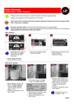
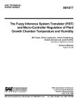
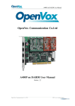
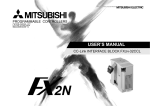
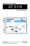
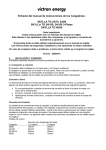
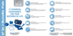
PB-600
Instruction Manual
PB-600 Instruction Manual
Index
0.Product description................................................................................. 1
1.Notes on operation ................................................................................. 1
2.Front and back panel .............................................................................. 1
3.Derating curve ........................................................................................ 2
3.1 Charging current VS temperature ...................................................... 2
3.2 Charging current VS input voltage ..................................................... 2
4.Function description for CN100 ............................................................... 2
5.LED Indication ........................................................................................ 3
6.Explanation of operation logic (charging stages)...................................... 3
6.1 2 stage charging (flick switch to "2" stage) ......................................... 3
6.2 3 stage charging (flick switch to "3" stage) ......................................... 4
6. 3 8 stage charging (flick switch to "8" stage) ......................................... 5
7.Function description ............................................................................... 6
7.1 Input voltage .................................................................................... 6
7.2 PFC ................................................................................................. 6
7.3 Remote control ................................................................................. 6
7.4 2, 3, or 8 stage charging mode selection ........................................... 7
7.5 Reverse polarity protection ............................................................... 7
7.6 Fan speed control ............................................................................. 7
7.7 Charger OK relay (RY15) .................................................................. 7
7.8 Output OK relay (RY13) .................................................................... 8
7.9 Temperature compensation .............................................................. 8
8.Wiring for battery................................................................................... 8
9.Suggested battery capacity ..................................................................... 9
10.Series and parallel connection of batteries ............................................ 9
11.Recom mended wire sp ecification ....................................................... 9
12.Failure correction notes ........................................................................ 10
Aug. 2013 Version 10
0.Product description
PB-600 is MW's next generation smart charger. It has many of the protective features
th a t co n su mer s wo u ld like to h ave in a cha rg er inclu din g ba tte ry misco nne ctio n
(wrong voltage), reverse polarity, battery disconnection or not connected, and battery
failure analysis. The latest high efficien cy switc hing topolog y plus microc ontrolle r
po wer m an age men t ar e utilize d in its d esig n. T hree typ es o f cha rgin g cu rve s ar e
offered for lead acid battery charging, 2 stages for quick charging, 3 stages (quick +
float), and 8 stages for optim ize d chargi ng. C harging stage selection can be easily
made by th e user through the selection switch on the front panel.
Depending on battery brand and type (lead acid, gel, lithium iron, and lithium manganese);
th e battery ma y require spe cial cha rgin g cu rves and adjustm ent to t he p rote ctiv e
functions which differs from the standard settings. The charging curves and protective
functions can be customized by reprogramming its firmware. Basically, you can change
the voltage/current settings of each individual stage plus adjust or cancel the protective
functions. Please note, the factory charging curve is for charging lead-acid battery.
Please contact MW regarding other types of battery charging requirements.
1.No tes on operation:
◎Designed for cha rging lead acid b attery.
◎Must be installed in a dry and well ventilated area. It should not be exposed to rain
or snow.
◎The cab les b etween cha rger and bat tery shou ld b e ke pt a s sh ort a s po ssi ble t o
prevent excessive voltage drop. Too much voltage drop will lead to longer charging
period.
◎Plea se m ake sure ch arging v oltage a nd c urre nt m eets ba ttery specific atio n.
◎Refr ain from con necting new and old batt erie s in seri es.
◎Charger should be in the O FF mode before ma king battery connection or dis con nec tion.
◎T hre e ye a rs w ar rant y is prov ide d un der norm al o per a tin g co n dit io ns . Fa ilur e
resu lting fro m im prop er o per atio n will res ult i n ca ncel latio n of warrant y.
2.Front and back panel
AC INLET ON/ OFF SWITCH
ON
F an
Venti lation
H ole
OFF
A C I NP UT
Figu re 2.1 Front Pa nel
1
Battery
Positive
LED
Indi cator
Common
Negative
Power
Stage 8/3/2
2/3/8 stag e
se lectio n switc h
Func tion
Connec tor
10
+
WARNING :
-
Please check batter y
polarity before
connection
Battery
Figure 2. 2 Back P anel
Assemb ly guideline s:
1.The ch arger should be turned OFF prior to battery connection. Suitable wire gauge
should be chosen based on rated charging current of the charger unit. Double-check
battery polarity before making the battery connection. Positive terminal of the charger
must be co nnected to + of the b atte ry and ne gative terminal to of the battery. Also,
make sure the positive and neg ative ter min als of the charger are not accidentally
shorted together.
2. Afte r plugg ing in th e A C pow er c ab le, flick the ON/ OFF (0/-) sw itch to th e O N (-)
positio n. T he LED indicator on the switch will lig ht up.
3.De rating c urve
3.1 Cha rging curren t VS temperature
3.2 Charging current VS inpu t voltage
100
100
90
80
80
60
70
60
40
50
20
-20
40
0
10
20
30
40
50
60
70 (HORI ZONTAL)
90
95
100
115
264
INPUT VOLTAGE (VAC) 60Hz
AMBIENT TEMPERATURE (℃)
4.Fu nction desc ription for CN100
Pin No.
Function Description
Rela y con tact rating (max.): 3 0V/1A. "Short" when batter y is full.
1,2
RY13
"Open" when battery is s till ch arging.
2
Pin No.
Function Description
5,6
RY15
Re lay conta ct ra ting (max.): 30V/1A. "Short" w hen the unit is work ing
prope rly. "Open" when th e u nit has faile d or prot ect io n has a ctiv ated.
7,8
Temperature sensor which comes with the char ger ca n be conne cted
to the unit to allow temperature compensation of the charging v oltage.
GND/RTH
If the temperature sen sor is not used , the charge r ca n sti ll w ork
norma lly.
9,10
RC-/RC+
Turn the output ON an d OFF by electrical or dr y c ontac t be tween
pin10 (RC+) and pin9 (RC-). Open: start charging. Short: s top charging.
5.LE D In dication
Co lor
Statu s
Stea dy
Re d
Flas hin g
Fail
Orang e
Charging
Green
Full
Charging
Type s of failure: 1 Battery disconnected
2 Damaged battery 3 Rever se polari ty
4 Incorrect battery voltage (e.g. PB-600-12 connected to 24V battery)
5 Activation of protection function (e.g. OTP, OVP, and Short)
6.Ex planation of operation logic (charg ing stages):
PB -60 0 ha s a t o ta l o f 3 cha rgin g m ode s to c ho os e from , 2 s tag e s, 3 sta ges , and
8 stages. 8 stages charging differ from 2 stages with the addition of pulse, soft start,
analysis, recondition, float, and mai ntain stages. 2 stages provide simple and quick
charging. 3 stages is sim ilar to 2 stages with the exception of not shutting OFF after
the battery is fully charged. Lastly, 8 stages will allow charging to maximum capacity.
User can select between 2,3 or 8 stages depend ing on their requirement.
6.1 2 s tage charging (flick switch to "2" stage)
During initial charge (stage 1), charger will provide maximum current to the battery.
The built-in fan will also turn ON. As the battery starts to get full, charging current
will gra dually decre ase (stage 2). When charging current decreas e to less than
10% of max. LED indicator w ill turn G reen to show a full charg e and the charger
will turn OFF.
Start
V boost
Charge Voltage
100%
10%
Charge Current
s tage 1
stage 2
Constant Current Constant Voltage
Color of LED
Orange
3
Battery Full
Green
State
PB-600-12
PB-600-24
PB-600-48
Constant
Current
40A
21A
10.5A
V boost
14.4V
28.8V
57.6V
Fig ure 6.1 2 stag e ch arging curve
Ex planation for 2 stag es charging curve
(0)Initial stage (battery ana lysis):
Check batte ry vo ltage le vel to see if it is within the normal range, w hether o r no t
a ba ttery is connected, o r if the batte ry is already full and further charging is no t
requ ired.
(1)Stage 1 (constant current):
A constant current is provided so the battery can be quickly charged to 2.4V per cell.
(2)Stage 2 (constant voltag e):
A constant voltage of 2.4V per cell is provided until the charging current naturally
tapers down to 10% then stop chargin g.
6.2 3 s tage charging (flick switch to "3" stage)
During initial charge (stage 1), charger will provide maximum current to the battery.
The built-in fan will also turn ON. As the battery starts to get full, charging current
will gradually decrease (stage 2: programmed to last no longer than 24hrs). When
charging current decrease to less than 10% of max. LED indicator will turn Green
to show a full charge. The charger will now maintain a float charge voltage (stage 3).
Start
V boost
V float
Charge Voltage
100%
10%
Charge Current
stage 1
Constant Current
stage 2
stage 3
Constant Voltage
Battery Full
Orange
Color of LED
Green
State
PB-600-12
PB-600-24
PB-600-48
Constant
Current
40A
21A
10.5A
V boost
Vfloat
14.4V
13.8V
28.8V
27.6V
57.6V
55.2V
F igure 6.2 3 stag e ch arging curve
4
Ex planation for 3 stag es charging curve
(0)Initial stage (battery ana lysis):
Check batte ry vo ltage le vel to see if it is within the normal range, w hether o r no t
a ba ttery is c onn ecte d, o r if th e battery is alre ady full and furth er c harg ing is no t
requ ired.
(1)Stage 1 (constant current):
A constant current is provided so the battery can be quickly charged to 2.4V per cell.
(2)Stage 2 (constant voltag e):
A constant voltage of 2.4V per cell is provided until the charging current naturally
tapers down to 10% then move on to stage 3.
(3)Stage 3 (Flo at voltage):
A float voltage of 2.3V per cell is provided so that the battery can maintain full charge.
*F or a pplic atio ns that utiliz e th e ch arge r (PB-60 0) to ch arge batterie s an d su ppl y
system power simultaneously( e.g. UPS system ), pl ease sel ect "3 stage" cha rgin g
for the best use of the c harger.
6.3 8 s tage charging (flick switch to "8" stage)
8 stage charging provides optimized charge to lead acid battery. It also prolongs
battery life and increase storage cap acity. Some of the ma in advantages are as
below:
◎Advantage of pulse stage: Use pulse current to revive aged battery.
◎Advantage of recondition stage: Allow full charge of battery.
◎A dva ntag e of floa t an d ma intain s tage : Aft er LED t urns gre en, m ainten ance
charge is provided so the battery is always in a full state. User will have access
to a full battery wh enever it is disconnected from the charger.
Start
Pulse
Ch arge
Soft
Start
Constant
Current
Constant
Voltage
Battery
Analysis
Recondition
Float
Charge
Maintain
Pulse
Soft
Start
Constant
Current
Cons ta nt
Volt age
Analysis
Re cond
Float
Maintai n
stage 1
stage 2
stage 3
stage 4
stage 5
stage 6
stage 7
stage 8
Charge
Voltage
Charge
Current
Color of
LED
Orange
Green
Figure 6 .3 8 stage charg ing curve
5
Ex planation for 8 stag es charging curve
(0)Initial stage (battery analysis):
Check batte ry vo ltage le vel to see if it is within the normal range, w hether o r no t
a ba ttery is connected, o r if the batte ry is already full and further charging is no t
requ ired.
(1)Stage 1 (pulse charging):
Pulse charging is used to revive tired lead acid battery which is either improperly
charged/discharged or allowed to self-discharge as occurs during non-use. Basically,
help to restore its norma l chemical properties.
(2)Stage 2 (soft sta rt):
Use low cha rge volt age and curr ent to prepa re th e ba ttery to acce pt u pco min g
bulk charging, so a better charge can be a pplied.
(3)Stage 3 (constant current):
A high constant curre nt is provided so the battery can be qu ickly charged to 2.4V
per cell.
(4)Stage 4 (constant voltage):
A constant voltage of 2.4V per cell is provided until the charging current naturally
tapers down to a low level.
(5)Stage 5 (analysis):
The cha rger will sto p ch argi ng fo r 2 m inu tes to de term ine battery sta tus. If th e
battery voltage is higher than 2.1 V per cell, the battery is d etermined as OK and
will move on to stage 6. If the battery voltage is lower than 2.1V per cell, the battery
fail indication will co me O N and the charger will stop charg ing.
(6)Stage 6 (rec ondition boost charge):
Boost voltage is provided to recondition the battery storage capacity to its original
state.
(7)Stage 7 (float ch arge):
A float voltag e o f 2.3V per cell is provided for extended period of tim e(abou t one
day ) so that the b atte ry can m aintain full charge.
(8) Stage 8 (ma intain):
Maintenanc e ch arge is p rov ided to c omp ens ate for b atte ry se lf-d isch arge an d
extend battery life.
7.Fu nction desc ription
7.1 Input v olta ge
◎Input voltage range is 90~264Vac or 12 7~370Vdc.
◎T he provided inpu t vo ltag e must fall w ithin the spe cifie d range otherwis e th e
unit may be non-functional also the active PFC circuit may fail or get damaged.
◎E ffic ienc y wil l ge t low er w hen inp ut v o ltag e is at lo w line. P lea se n ote, loa d
d erating will b e required w hen input voltag e is belo w 100Va c.
6
7.2 PFC
◎Built-in active PFC circuit: PF>0.95 when input voltage is between 90~230Vac
w ith full lo ad at the ou tput. On the other hand, if the inp ut vo ltage is >230V o r
outpu t is not a t full load, th e PF will drop be low 0.95.
7.3 Remote co ntrol
The charger can be turned O N/O FF by using the "remote control" function.
Bet ween RC+ (pin10)
an d RC- (pin 9)
Ch arge r
SW open
ON
SW closed
OFF
CN100
1 RY13 RY13 2
Power
Stage 8/3/2
NC
NC
RY15 RY15
10
GND RTH
9
+
-
RC- RC+
10
Battery
SW
7.4 2, 3, or 8 stage charging mode selection
Th e ch arge r fe a tur es u ser s ele ctab le 2 , 3, o r 8 s tag e ch argi ng. The cha rgin g
profile is selected by mo ving the slide sw itch on the back panel.
Switch
C hargin g mod e
Slide right
2 sta ge ch arging
Mid dle
3 sta ge ch arging
Slide left
8 sta ge ch arging
Power
Stage 8/3/2
10
Stage 8/3/2
+
-
Battery
7
7.5 Reverse polarity p rotection
With built-in battery reverse polarity detection circuit. When the battery is connected
in reverse at the output terminal of the charger, the output relay circuit will remain
ope n.
7.6 Fan sp eed con trol
With bu ilt-in fan speed control c ircu it, th e fa n will automa tica lly chan ge s pee d
dep ending on lo ad condition.
CN100
7.7 Charger OK relay (RY1 5)
Charger
1 RY13 RY13 2
NC
Be twe en pi n5 a nd pin 6
NC
RY15 RY15
Wor king n ormally
ON (s ho rt)
Failu re or p ro tection
func tion ha s activ ated
OF F ( ope n)
GND RTH
9
RC- RC+ 10
RY15
7.8 Ou tput OK relay (RY13)
CN10 0
1
Between pin1 and pin2
Color of LED
Bat tery full
O N (s hort)
Green
Cha rgin g
OF F (o pen)
Orange
Bat tery
RY13 RY13
NC
2
NC
RY15 RY15
GND RTH
9
RC- RC+ 10
RY13
7. 9 Temperature compensation
Temperature sensor which comes with the charger can be connected to the unit
to allow tem perature compensation of the charging voltage. If the tem perature
sensor is not used, the ch arger can still w ork normally.
Power
Stage 8/3/2
10
The te mpera ture
sensor can e ither
be atta ched t o the
battery or pla ced
in its s urroun ding
enviro nment .
+
-
B atte ry
NTC
8
8.Wiring for battery
Select suitable wire gu age based on rated charg ing current. Refer to the following
table for minimum wire gauge. We highly recommend using RED wire for + connection
and BLACK wire for-connection :
CROSS SECTION(mm 2 )
AWG
Max. Cu rrent(A)
UL1015(600V 105 ℃ )
14
2.1
12
12
3.3
22
10
5.3
35
7
10
46
6
16
60
4
25
80
9.Su gge sted battery capacity
Model
Battery capacity
P B-600-1 2
135-400AH
P B-600-2 4
70-210AH
P B-600-4 8
35-105AH
Note: 1.Using battery capacity larger than the suggested value will not lead to damage
of the batte ry. The main dra wba ck is it may take longer t o fu lly charg e th e
battery.
2.If you're unsure about max allowable charging current of your battery, please
refer to the battery's technical s pecification or consult its man ufa cturer.
10.S eries and parallel connection o f batteries
1.Ba tteries in series
Vo ltag e ca n be do uble d wh e n 2 ba tteri es a re c onn e cte d in seri es. H ow eve r, th e
capacity (Ah) will remain the same. For example, 2 x 12V 100Ah batteries connected
in series = 24V 100 Ah.
+
-
Battery
+
-
Battery
9
2.Ba tteries in parallel
Wh en 2 ba tt er ies a re c onn e ct e d i n pa ra ll e l, v o lta g e r e ma in s t h e s a m e an d th e
capacity (Ah) d oubles. For exam ple , 2 x 12V 100Ah batteries connected in parallel
= 12V 200Ah.
+
-
Battery
+
-
Battery
11.R ecommended w ire specification
Insta llation
Safet y ratin g
Max imum length
Desk top, counter top, chassis
box (mobile)
SP-2, SPE-2, SPT-2,SV,SVE,SVT
10ft (3 meter)
Grounded, fixed in place
(not mobile)
S, SE, SO, SP-3, SPT-3, ST, STO,
SJ, SJE, SJO, SJT, SJTO
Not specif ied
N ote: Please insta ll in accordance with the tab le ab ove. Wire gauge should be no
smaller than No. 18 AWG/3C. Socket type restricted to 15A, 125V (NEMA 5-15P)
or 15A, 250 V(NEMA 6-15P) with power cord length ranging from 1.8 meters
to 1 0 m eters.
12.Failure corre ction notes
Status
Unable to
cha rge
the battery
LED indicator
doe s not turn
Gre en after a
long charging
period
Possible reasons
Solu tions
ON/OFF switch in th e OFF position
Switch to the ON position
Battery reverse polarity
Reconnect using the
right polarity
Battery with higher volta ge is
con nected
Use battery with the
correct voltage
Input AC voltage is too low
Make sure input sou rce
is between 90~264VAC
Battery exceeded lifespan or
damaged
Replace with a new
battery
Output cables are too thin
Replace with suitable
wire gauge
If you are not able to clear the failure condition, plea se contact Mean Well o r
any o f our distrib utors fo r repair service .
10
N o . 2 8 , Wu q u a n 3 r d R d ., Wu g u D i s t . , Ne w Ta i pe i C i t y 2 4 8 , Ta i wa n