1
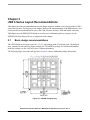
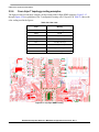
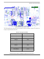
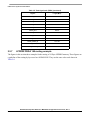
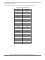
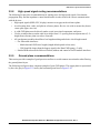
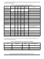
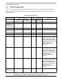
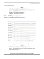
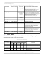
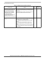
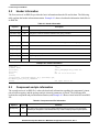
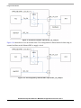
i.MX 6 Series Layout Recommendations
Consider the following when designing the stackup and selecting the material for your board.
• Board stack-up is critical for high-speed signal quality.
• You must preplan impedance of critical traces
• High-speed signals must have reference planes on adjacent layers to minimize cross-talk.
• FSL reference design equals Isola 370HR.
• FSL validation boards equals Isola FR408.
The recommended stackup is 6-layers, with the layer stack as shown in the following figure. The lefthand
image shows the detail provided by Freescale inside the fabrication detail as a part of the Gerber files. The
righthand side shows the solution suggested by the PCB fabrication company for our requirements.
Additional power planes to support i.MX 6Dual/6Quad and i.MX 6Solo power options only.
Figure 2-5. Layer stack EVK board
The following table shows a working stack-up implementation:
Table 2-1. Stackup implementation
Single ended
Layers
Differential
Trace width Impedance Trace width Trace spacing Impedance Trace width Trace spacing Impedance
(Mils)
(Ωs)
(Mils)
‘Airgap’ (Mils)
(Ωs)
(Mils)
‘Airgap’ (Mils)
(Ωs)
TOP
4.75
50
INT1
5.5
50
BOT
4.75
50
4.2
4.8
90
3.5
5.5
100
4.2
4.8
90
3.5
5.5
100
Hardware Development Guide for i.MX 6SoloLite Applications Processor, Rev. 1
Freescale Semiconductor
2-5