1
TCAD Driven CAD
A Journal for Circuit Simulation and SPICE Modeling Engineers
BSIM3SOI Version 3.0 Model Released in SmartSpice
Introduction
BSIM3SOI version 3.0 model was released on May 2002
by UC Berkeley. This model includes both Partially
depleted and Fully depleted models. This model is now
implemented in SmartSpice and can be selected according
to LEVEL selector.
LEVEL=33 selects BSIM3SOI v3.0 model.
A new full-depletion (FD) module has been included to
provide better fitting to FD SOI devices. This can be
invoked setting the model parameter SOIMOD=1.
The partially-depletion (PD) module is by default identical
to latest version of BSIM3SOI PD version 2.2.3 (also
supported in SmartSpice with previous versions setting
LEVEL=29). This can be invoked setting the model
parameter SOIMOD=0.
In the SmartSpice implementation of the BSIM3SOI v3.0
model, enhanced convergence is obtained by properly
handling GMIN and DCGMIN control options during
transient and DC analysis. The GMIN option connects a
conductance in parallel with the bulk diodes and
between drain and source.
The option VZERO defines the Modified Nodal
Analysis (MNA) formulation. The VZERO = 2 option is
recommended when simulating in the time domain
relatively large circuits with hundreds or thousands of
transistors. It accelerates simulation and increases the
accuracy of simulation results.
The option CAPDC=1 allows the user to see charge and
capacitances in DC (see output variables).
New Gate-to-Channel current (Igc) and new Gate-toSource/Drain currents (Igs and Igd) components have
been added in BSIM3SOI v3.0. By default, these
currents are set to 0 in order to stay compatible with
previous version but can be accounted turning on the
new selector IGCMOD.
The parameter checking procedure initially used for
BSIM3v3 and BSIM4 has been extended to BSIM3SOI
v3.0. This checking procedure verifies some critical
parameters values, and output warnings and/or errors
to the screen or to a logfile.
Gate-to-Body tunneling current was taken into account
in BSIM3SOI v2 PD (LEVEL=29) model turning on
IGMOD selector. In BSIM3SOI v3.0, identical expressions
are used for the calculation of this gate tunneling current
component but the selector is named IGBMOD now.
BSIM3SOI v3.0 model has been optimized to take advantage of the multi-processor machines. The simulation is
speed up when SmartSpice is run on parallel architectures
without influence on the accuracy.
A minor bug has been fixed in the self-heating algorithm.
Continued on page 2....
Implementation
The present section provides all the information needed
to understand and use the BSIM3SOI v3.0 model.
The SmartSpice implementation of the BSIM3SOI v3.0
model is close but not identical to UC Berkeley release.
The SmartSpice implementation provides a number of
improvements and additional parameters currently
unsupported in Berkeley’s BSIM3SOI v3.0 model.
Volume 12, Number 7, July 2002
INSIDE
A New Surface-Potentials Based
MOSFET Model : HiSIM . . . . . . . . . . . . . . . . . . . . . . . 5
HiSIM version 1.1 Model Released in UTMOST III . . . . . 8
Calendar of Events . . . . . . . . . . . . . . . . . . . . . . . . . . . . 16
Hints, Tips, and Solutions . . . . . . . . . . . . . . . . . . . . . . . . 17
SILVACO
INTERNATIONAL
Major Features
New version BSIM3SOI v3.0 includes the binning feature
to enhance the model flexibility and fixes some bugs
found in the previous BSIM3SOI PD v2.2.3.
BSIM3SOI v3.0 has the following new features relative
to BSIM3SOI PD v2 [1]:
●
New features have been added in BSIM3SOI v3.0
model:
Real floating body simulation in both C-V and I-V.
The body potential is determined by the balance of all
the body current components
●
Enhancements in the threshold voltage and bulk charge
formulation of the high positive body bias regime
●
An improved parasitic bipolar current model. This
includes enhancements in the various diode leakage
components, second order effects (high-level injection &
early effect), diffusion charge equation and temperature
dependence of the diode junction capacitance
●
An improved impact ionization current model. The
contribution from BJT current is also modeled by the
parameter FBJTII
●
Instance parameters (PDBCP, PSBCP, AGBCP, AEBCP,
NBC) are provided to model the parasitics of devices
with various body-contact and isolation structures
●
Gate-to-Channel current component Igc splitted into
two components Igcs and Igcd
●
Gate-to-Source/Drain tunneling currents (Igs and
Igd) between the gate and the source/drain diffusion
regions
●
Gate-to-Body tunneling current (Igb)
For more details concerning the physical expressions of
BSIM3SOI v3.0 model, please refer to SmartSpice
Modeling Manual Volume 3 [3].
Model Parameters
BSIM3SOIv3 model LEVEL=33 supports all model
parameters of BSIM3SOI Partially depleted LEVEL=29
and Fully depleted LEVEL=26 models. The additional
parameters listed in Table 1 correspond to BSIM3SOIv3
model released by UC Berkeley in May 2002 only.
●
An external body node (the 6th node) and other
improvements are introduced to facilitate the modeling
of distributed body-resistance
●
Self-heating: an external temperature node (the 7th
node) is supported to facilitate the simulation of
thermal coupling among neighboring devices
Silvaco Improvements
●
A unique SOI low frequency noise model, including a
new excess noise resulting from the floating body effect
The option VZERO=2 allows faster runtime when large
circuits are used.
●
Width dependence of the body effect is modeled by
parameters (K1, K1W1, K1W2)
●
Improved history dependence of the body charges
with two new parameters (FBODY, DLCB)
The EXPERT option can be specified to detect possible
problems in models, before and during simulation,
such as:
Options
●
negative conductances GM, GDS and GMBS
negative gate capacitances
●
An instance parameter vbsusr is provided for users to
set the transient initial condition of the body potential;
●
●
The new-charge thickness capacitance model
introduced in BSIM3v3.2, CAPMOD3, is included
The feature summary of the parameter checking in
BSIM3SOI3 v3.0 is provided below:
●
Gate-to-Body tunneling current
●
●
A body halo sheet resistance
To read warnings on screen, set the EXPERT option
to 777
●
A minimum width fro thermal resistance calculation
●
●
A higher limit for exponential functions
To perform all possible tests, add PARAMCHK=1 to
the model card.
●
To avoid writing any logfile, add PARAMCHK=-1 in
the model card.
BSIM3SOI v3.0 has the following new features relative
to BSIM3SOI FD v2 [2]:
●
Supports external body bias and backgate bias: a total
of 5 external nodes
●
Improved self-heating implementation
●
New depletion charge model (EBCI) introduced for
better accuracy in capacitive coupling prediction
●
In order to control the checking procedure, two values
are used :
Single I-V expression to guarantee continuities of Ids,
Gm, and Gds and their derivatives for all bias conditions
The Simulation Standard
Page 2
●
The EXPERT option : if equal to 777, non-fatal warnings
will be displayed on screen. The fatal warnings are
always sent to screen.
●
The PARAMCHK model parameter : if equal to 1 or true,
a full parameter testing will be performed, issuing
warnings when suspicious parameters values are found
July 2002
Parameter
Description
SOIMOD
SOI model selector (0 for BSIMPD and 1 for BSIMFD)
Units
-
Default
0
VBSA
Offset voltage due to non-idealities
V
0.0
NOFFFD
Smoothing parameter in FD module
-
1.0
VOFFFD
Smoothing parameter in FD module
V
0.0
K1B
First backgate body effect parameter
-
1.0
K2B
Second backgate body effect parameterfor short channel effect
-
0.0
DK2B
Third backgate body effect parameter for short channel effect
-
0.0
DVBD0
First short channel effect parameter in FD module
-
0.0
DVBD1
Second short channel effect parameter in FD module
-
0.0
MOINFD
Gate bias dependence coefficient of surface potential in FD module
-
1.0E+3
IGCMOD
Global model selector for Igs, Igd, Igcs, Igcd
-
0
IGBMOD
Global model selector for Igb
-
0
AIGC
Parameter for Igs, Igd, Igcs, Igcd
(F.s^2/g)^.5.
m^-1
0.43 (NMOS)
0.31 (PMOS)
BIGC
Parameter for Igcs and Igcd
(F.s^2/ g)^.5.
mV^-1
0.054 (NMOS)
0.024 (PMOS)
CIGC
Parameter for Igcs and Igcd
V^-1
0.075 (NMOS)
0.03 (PMOS)
AIGSD
Parameter for Igs and Igd
(F.s^2/ g)^.5.
m^-1
0.43 (NMOS)
0.31 (PMOS)
BIGSD
Parameter for Igs and Igd
(F.s^2/g)^.5.
mV^-1
0.054 (NMOS)
0.024 (PMOS)
CIGSD
Parameter for Igs and Igd
V^-1
0.075 (NMOS)
0.03 (PMOS)
DLCIG
S/D overlap length for Igs/Igd
NIGC
Parameter for Igs, Igd, Igcs, Igcd
LINT
POXEDGE
Factor for the gate oxide thichness in the dource/drain overlap regions
-
1.0
NTOX
Exponent for the TOX ratio
-
1.0
TOXREF
Targert oxide tickness in gate tunnelling
m
2.5e-9
TOXQM
Equivalent oxide tickness in gate tunnelling
m
TOX
1.0
Table 1. Additional parameters to BSIM3SOI v2 PD and FD for BSIM3SOI v3.0 model
The logfile contains the warnings concerning models
and devices, as well as the number of fatal errors and
clipped parameters. It is created when PARAMCHK > 0.
If the logfile cannot be created (lack of disk space, no write
permissions, etc...), warnings will be sent to screen.
Fatal errors are always displayed on screen, and make
the simulation stop. A summary is also always
displayed on screen, giving the number of fatal errors
and clipped parameters.
SmartSpice includes two algorithms for the BYPASS
option which can be invoked setting BYPASS=1 and
BYPASS=2. In the best case, the performance of
simulations has been improved of 30%.
If it is created, the logfile is named after the netlist’s
filename, appended with the model’s type, and the
extension chk. For example : netlist1.bsim3soi_v2.chk
Parameter
Description
VERSION
Version selector
Units
Default
-
3.0
SMART
Improvement selector
-
2
LMIN
Minimum length for binning
m
0.0
LMAX
Maximum length for binning
m
1.0
WMIN
Minimun width for binning
m
0.0
WMAX
Maximun width for binning
m
1.0
TMIN
Minimum temperature for binning
degC
0.0
TMAX
Maximum temperature for binning
degC
0.0
BULK
Default body (bulk) node name
-
“not given”
BACKGATE
Default backgate (substrate) node name
-
“not given”
New Model Parameters
New model parameters are listed in Table 2.
The four model parameters (LMIN, LMAX,
WMIN and WMAX) are used for binning to
select a model. Moreover, a temperature
binning capability has been added (TMIN and
TMAX). For the bin-ning, Silvaco has also
added new binned model parameters shown in
Table 3.
Table 2. SmartSpice Specific parameters.
July 2002
Page 3
The Simulation Standard
The SMART model parameter
allows to switch on
Silvaco improvements
which are not compatible
with original Berkeley
model. SMART model
parameter has been created
as follows :
●
if SMART = 0: the original
Berkeley model is used
with its different versions
●
if SMART > 0: Silvaco’s
ACM common equations are
used (geometry, bulk
diodes and drain/source
series resistances)
AT
GAMMA1
GAMMA2
VBM
VBX
XT
KT1
KT1L
KT2
UA1
UB1
UC1
UTE
RTH0
PRT
CGDL
CGSL
CKAPPA
CF
CLC
CLE
XJ
RBODY
CSDMIN
CTH0
ASD
CSDESW
CJSWG
PBSWG
MJSWG
TT
XBJT
XDIF
XREC
XTUN
LN
NDIF
LDIF0
TCJSWG
TPBSWG
NTRECF
NTRECR
Table 3. New binning model parameters
References
[1] BSIM3SOI PD v2.2 User’s Manual, 1999, Department of
EECS, University of California, Berkeley
[2] BSIM3SOI FD v2.1 User’s Manual, 1999, Department of
EECS, University of California, Berkeley
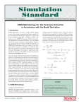
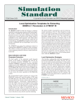
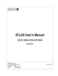
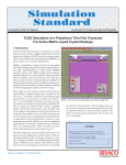
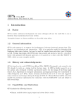
BSIM3SOI v3.0 Model Characteristics
[3] SmartSpice Modeling Manual Volume 3
Figure 1. Selfheating effect on output characteristics
(SOIMOD=0)
Figure 2. Gate tunneling currents (SOIMOD=0).
The Simulation Standard
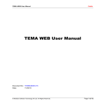
Figure 3. Ring oscillator (SOIMOD=0).
Page 4
July 2002
A New Surface-Potentials Based
MOSFET Model : HiSIM
HiSIM stands for Hiroshima-university STARC IGFET
Model. It has been developed at Hiroshima University
starting in 1992. It has been released as version 1.1.0 in
July 2002.
Surface Potentials
HiSIM and Conventional MOSFET Models
To compute these charges, the surface potentials at
source side φS0 and φSL at drain side are needed. These
two values are directly dependent on technological
parameters. They are calculated by solving the Poisson
equations :
HiSIM is based on charge control and charge flow
through the channel. The inversion layer charge and the
depletion layer charge depend on the surface potential
along the channel.
HiSIM is interesting because of the way it models
channel current. Conventional MOSFET models simplify computation of channel current by splitting calculation between a linear dependent region (due to strong
inversion) and a saturation region (due to velocity saturation). Discontinuities can appear in IDS, in the transition region. Therefore, to avoid these discontinuities,
extra parameters are used to smooth the transition
between the different set of equations. These parameters are not physical, they are just needed to correctly
fit the device’s characteristics.
COX ⋅ (VG′ − φS 0 ) =
2 LD qNSUB ⋅
{exp(− β ⋅ (φ
S0
np 0
−1 + p ⋅
p0
COX ⋅ (VG ′ − φSL ) =
2 LD ⋅ qNSUB ⋅
{exp(− β ⋅ (φ
SL
np 0
−1 + p ⋅
p0
Parameter number is dramatically reduced (by a
factor 5) for the same level of accuracy. Parameters
are not interdependent anymore, making extraction
easier. Furthermore, a set of parameters is valid for
all channel lengths.
))+ β ⋅ (φSL − VBS )
1/
2
The surface potentials side φS0 and φSL are distributed in
the channel according to the schematic shown in Figure 1
HiSIM is based on a charge-sheet model. IDS current is
described using only one equation, and there-fore is
continuous over the whole range of operating regions.
This improves MOSFETs modeling regarding at least
two points :
•
− VBS
[exp(β ⋅ φSL )− β ⋅ (φS 0 − VBS )− exp(β ⋅ (VBS -VDS ))]}
The conclusion is that dividing the I DS current into
different regions and equations is not correct anymore
for short-channel transistors.
Equations are continuous over all operation regions,
as well as their derivatives. This is a key point for
today’s analog circuits, where performance is very
much dependent on high order derivatives.
1/
2
[exp(β ⋅ φS 0 )− β ⋅ (φS 0 − VBS )− exp(β ⋅ VBS )]}
Another drawback of common models is the bad
modeling of short-channel effects. For deep sub-micron
MOSFETs, this effect dominates the IDS-VDS characteristic.
Conventional models do not use equations based on
physical concepts, but add fitting parameters to each
modeled effect to account for short-channel effect. This
results in many unphysical fitting parameters, and
makes parameter extraction difficult.
•
− VBS ))+ β ⋅ (φS 0 − VBS )
Figure 1.
July 2002
Page 5
The Simulation Standard
Both Poisson equations are solved iteratively,
because they are implicit. Using approximations
to get explicit equations with regard to terminal
voltages would not be an improvement: it would
reduce accuracy, and convergence is quickly
obtained when solving these two equations.The
internal New-ton’s algorithm converges within
one to ten iterations, depending on the circuit.
This is acceptable for a circuit simulator, since
simulation times are comparable to those
observed using other models.
The screenshot in Figure 2 shows the surface
potentials evolution when VGS increases.
New in Version 1.1.0
The last improvements are: shallow-trench-isolation
(STI) is accounted for in leakage current model, a
lateral-field-induced capacitance has been added,
and the resistance model has been improved,
requiring two more model parameters. These
new modeling equations make HiSIM even more
accurate.
Figure 1.
The model card for HiSIM includes the following parameters:
Modeled Effects
Technological parameters
HiSIM computes charge control using dedicated
parameters to account for the following physical effects:
TOX
Oxide thickness
XLD
Gate-overlap length
●
Short-channel
XWD
Gate-overlap width
●
Reverse short-channel
XPOLYD
●
Pocket implantation
Difference between gate-poly
and design length
●
Quantum
●
Poly-depletion
●
Universal mobility
●
Channel-length modulation
●
●
●
TPOLY
Height of the gate poly-Si
RS
Source contact resistance
RD
Gate contact resistance
NSUBC
Substrate-impurity concentration
NSUBP
Maximum pocket concentration
Velocity overshoot
VFBC
Flat-band voltage
Symmetry at VDS=0
LP
Pocket penetration length
Shallow trench isolation (version 1.1.0 only)
XJ
Junction depth
XQY*
Distance from D junction to
maximum electric field
HiSIM and SmartSpice
HiSIM is available within SmartSpice when LEVEL=111
is specified. This model has been implemented using
reference versions 1.0.0 and 1.1.1. The user can select
one of these version using a selector, VERSION. Beyond
this material, SmartSpice provides all the services
commonly proposed for MOSFET models. Among them are:
Temperature dependence
BGTMP1
Bandgap narrowing
BGTMP2
Bandgap narrowing
Quantum effect
●
Advanced geometry scaling (ACM)
QME1
●
Simulation performance using VZERO and BYPASS
options
Coefficient 1 for quantum
mechanical effect
QME2
●
Friendly diagnostics to help with convergence issues
Coefficient 2 for quantum
mechanical effect
●
Extrinsic elements such as junction diodes/capacitances
QME3
Coefficient 3 for quantum
mechanical effect
The Simulation Standard
Page 6
July 2002
Poly depletion
PGD1
Strength of poly depletion
PGD2
Threshold voltage of poly depletion
PGD3
VDS dependence of poly depletion
Short channel
PARL1
Strength of lateral-electric-field
gradient
PARL2
Depletion width of channel/
contact junction
SC1
Short-channel coefficient 1
SC2
Short-channel coefficient 2
SC3
Short-channel coefficient 3
SCP1
Short-channel coefficient 1 for
pocket
SCP2
Short-channel coefficient 2 for
pocket
SCP3
Short-channel coefficient 3 for
pocket
VOVERP
LGATE dependence of velocity
overshoot
RPOCK1
Resistance coefficient 1 caused
by the potential barrier
RPOCK2
Resistance coefficient 2 caused
by the potential barrier
RPOCP1*
Resistance coefficient 3 caused
by the potential barrier
RPOCP2*
Resistance coefficient 4 caused
by the potential barrier
Channel-length modulation
CLM1
Hardness coefficient of
channel/contact junction
CLM2
Coefficient for QB contribution
CLM3
Coefficient for QI contribution
Substrate current
Narrow channel
SUB1
Substrate current coefficient 1
SUB2
Substrate current coefficient 2
SUB3
Substrate current coefficient 3
WFC
Threshold voltage reduction
MUEPH2
Mobility reduction
W0
Minimum gate width
GLEAK1
Gate current coefficient 1
WVTHSC*
Short-channel effect at the
STI edge
GLEAK2
Gate current coefficient 2
GLEAK3
Gate current coefficient 3
NSTI*
Substrate impurity concentration
at the STI edge
WSTI*
Width of the high-field region at STI
Gate current
GIDL current
Mobility
GIDL1
GIDL current coefficient 1
GIDL2
GIDL current coefficient 2
GIDL3
GIDL current coefficient 3
VDS0
Drain voltage for extracting the
low-field mobility
MUECB0
Coulomb scattering
MUECB1
Coulomb scattering
MUEPH0
Phonon scattering
MUEPH1
Phonon scattering
MUETMP
Temperature dependence of
phonon scattering
MUESR0
Surface-roughness scattering
MUESR1
Surface-roughness scattering
NDEP
Coefficient 1 of effective-electric
field
VZADD0
Symmetry conservation
coefficient 1
NINV
Coefficient 2 of effective-electric
field
PZADD0
Symmetry conservation
coefficient 2
NINVD
Modification of NINV
BB
High-field-mobility degradation
VMAX
Maximum saturation velocity
VOVER
Velocity overshoot effect
July 2002
Flicker noise
NFALP
Contribution of the mobility
fluctuation
NFTRP
Ratio of trap density to
attenuation coefficient
CIT
Capacitance caused by the
interface trapped carriers
Symmetry at VDS=0
* available only in version 1.1.0
Page 7
The Simulation Standard
HiSIM version 1.0 Model Released in UTMOST III
Introduction.
effect parameters: One for the standard short channel
effect, and the other for the reverse short channel effect.
We will see later in this section how this two effects
lead to separate the L-array of devices in two parts
depending on which parameters need to be optimized.
HiSIM is a MOSFET model for SPICE circuit simulation
that has been developed by Hiroshima University and
STARC Company.
This model present several advantage on the extraction
point of view, with a reasonable number of parameters,
a physical reliability of the equations for a wide range
of geometries (down to 0.1um) and a unified description
of devices characteristics for all bias conditions.
Restrictions This article gives a procedure to extract
most of HiSIMv1.0 parameters. However, some effects
are not taken into account, their corresponding
parameters extraction will require another article in a
future Simulation Standard. Those parameters are:
Narrow channel, Channel-length modulation, Substrate
Gate and GIDL current, 1/f Noise parameters.
It has been implemented in Silvaco Spice Simulator,
SmartSpice and in our current extraction software
UTMOST III.
This article presents an efficient extraction procedure
for HiSIMv1.0 parameters using UTMOST III. This
procedure will lead to a model card accurate for a wide
range of geometries. It is widely inspired from the one
proposed by STARC in its “HiSIM1.0 User’s Manual”, but
it has been adapted and optimized for UTMOST III users.
Model Parameters
Data Collection and Initial Parameter
Geometry Selection
The extraction procedure presented in this article
requires DC measurement that can be obtained using
the BSIM3_MG routine on a Large and Wide device
and an L-array of devices (See articles for BSIM3_MG
extraction routine in the previous issues of the
Simulation Standard.). In this case “BSIM3_MG” should
be used as a measurement routine only.
As mentioned above, we have three “group” of device
geometry that will be used separately depending on the
kind of parameters that will be extracted.
To get significant results for an HiSIMv1.0 extraction,
the initial set of values for HiSIM parameters is important.
UTMOST III provides you a default model card that
should be used as a starting point. Detail of this model
card is shown in Table 1.
The Long and Wide device used for mobility, flat band
voltage and substrate impurity concentration
parameters extraction.
The split of the L-array should be done according to the
Vth dependency on the channel length, which can be
observed through UTMOST validate routine. The
L-array of devices will be split in two parts depending on
what kind of short channel parameters will be optimized.
Following STARC recommendations, IDS vs. VGS
measurements should be performed for VDS=50mV
and 1V. IDS vs. VDS measurements will be performed
for VBS=0V and -1V. For those last characteristics, the
Voffset value which is used to calculate the first VGstart
value (Vgstart = VTextracted + Voffset) defaults to 0.2V.
The recommended number of points per sweep in the
BSIM3_MG routine is 51 and the number of VGS steps
and VBS steps are 5.
In addition, to be able to extract Quantum Mechanical
Effect parameters and Poly Depletion effect parameters,
Intrinsic Gate capacitance vs. Vgs should be measured
on Large and Wide device.
The typical number of geometries used for model
parameter extraction is 10. There should be a large
device with wide W and long L (to avoid short channel
or narrow width effects) to extract the root parameters
(as mobility parameters, substrate impurity concentration
and flat band volt-age). An array of short L devices will
be used to extract short channel parameters. It has to be
noticed that HiSIM includes two kind of short channel
The Simulation Standard
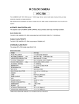
Figure 1. VTH dependence on L - UTMOST routine “Validate“.
Page 8
July 2002
Parameter
VERSION
Description
Units
HiSIM Model version number (SmartSpice specific)
Default
1.1
Technological parameters
TOX
oxide thickness
m
XLD
gate-overlap length
m
5E-9
0
XWD
gate-overlap width
m
0
XPOLYD
difference between gate-poly and design lengths
m
0
TPOLY
height of the gate poly-Si
m
0
RS
source-contact resistance
Vm/A
80E-6
RD
Drain contact resistance
Vm/A
80E-6
NSUBC
substrate impurity concentration
cm-3
1E17
NSUBP
maximum pocket concentration
cm-3
1E17
VFBC
flat-band voltage
V
-1
LP
Pocket penetration length
m
15E-9
XJ
Junction depth
m
0
Temperature dependence parameters
BGTMP1
bandgap narrowing
eV/K
90.25E-6
BGTMP2
bandgap narrowing
eV/K^2
100E-9
Quantum effect parameters
QME1
Coefficient for quantum mechanical effect
Vm
40E-12
QME2
Coefficient for quantum mechanical effect
V
300E-12
QME3
Coefficient for quantum mechanical effect
m
0
Poly depletion effect parameters
PGD1
strength of poly depletion
V
10E-3
PGD2
threshold voltage of poly depletion
V
1
PGD3
Vds dependence of poly depletion
0.8
Short Channel effect parameters
PARL1
strength of lateral electric field gradient
PARL2
depletion width of channel/contact junction
m
1
0
SC1
short channel coefficient 1
V -1
0
SC2
short channel coefficient 2
V -2
0
SC3
short channel coefficient 3
V -2 m
0
SCP1
Short-channel coefficient 1 for pocket
V -1
0
SCP2
Short-channel coefficient 2 for pocket
V
-2
0
SCP3
Short-channel coefficient 3 for pocket
V -2 m
0
Threshold voltage reduction
F cm -2 m
0
Narrow channel
WFC
MUEPH2
mobility reduction
W0
minimum gate width
0
log(cm)
0
Mobility
VDS0
drain voltage for extractions the low field mobility
V
50E-3
MUECB0
Coulomb scattering
cm 2 V -1 s -1
300
MUECB1
Coulomb scattering
cm 2 V -1 s -1
30
Table continued on page 10....
July 2002
Page 9
The Simulation Standard
Parameter
Description
MUEPH0
phonon scattering
MUEPH1
phonon scattering
Units
Default
cm2 (Vs)-1 (Vcm-1) MUEPH1
300E-3
25E3
MUETMP
temperature dependence of phonon scattering
MUESR0
surface roughness scattering
1.5
cm2 (Vs)-1 (Vcm-1) MUESR1
2
MUESR1
surface roughness scattering
2E15
NDEP
coefficient of effective electric field
1
NINV
coefficient of effective electric field
0.5
V
-1
NINVD
modification of NINV
BB
high field mobility degradation
1E-9
VMAX
maximum saturation velocity
cm/s
4E6
VOVER
velocity overshoot effect
cm VOVERP
10E-3
VOVERP
Lgate dependence of velocity overshoot
2
100E-3
2
RPOCK1
resistance coefficient caused by the potential barrier
V A
RPOCK2
resistance coefficient caused by the potential barrier
V
-RPOC1
um
RPOC2-1
10E-3
100E-3
Channel length modulation
CLM1
hardness coefficient of channel / contact junction
700E-3
CLM2
coefficient for Qb contribution
2
CLM3
coefficient for Qi contribution
1
Substrate current
SUB1
substrate current coefficient 1
V -1
SUB2
substrate current coefficient 2
V
SUB3
substrate current coefficient 3
10
20
0.8
Gate current
GLEAK1
gate current coefficient 1
AV-3/2 C -1
10E3
GLEAK2
gate current coefficient 2
Vcm -1 V -1.5
20E6
GLEAK3
gate current coefficient 3
300E-3
GIDL current
GIDL current coefficient 1
AV -3/2 C -1 m
GIDL2
GIDL current coefficient 2
-1
GIDL3
GIDL current coefficient 3
GIDL1
Vcm V
-1.5
5E-6
1E6
300E-3
1/f Noise
NFALP
contribution of the mobility fluctuation
Vs
1E-16
NFTRP
ratio trap density to attenuation coefficient
V -1 cm -2
10E6
CIT
capacitance caused by the interface trapped carriers
Fcm -2
0
Conservation of the symmetry at Vds=0 for Short-Channel MOSFETs
VZADD0
symmetry conservation coefficient
V
10E-3
PZADD0
symmetry conservation coefficient
V
5E-3
Table 1: HiSIMv1.1 default model card
Standard short channel effect makes VTH grows with L gate,
while Reverse short channel effect has the opposite influence.
includes devices from 10x0.13 to 10x0.11. This split of
the L-array is valid for low VDS.
The bigger devices of the L-array will be used for
reverse short channel effect parameters, while the smaller
devices, will be used for standard short channel effect.
VTH dependence on L for high VDS (VDS=1V) will
show a middle group including devices from 10x5 to
10x0.5 while short group will include device from
10x0.15 to 10x0.11.
On the example shown in Figure 2, the middle group
includes devices from 10x5 to 10x0.2 while short group
July 2002
Page 10
The Simulation Standard
Figure 3. Local optimization strategy definition screen
for Strategy#30 (idvg_large_HiSIM)
Figure 2. VTH dependence on L for a High VDS - UTMOST routine “Validate”.
Figure 4. Local optimization target selection screen for
Strategy#30 (idvg_large_HiSIM)
Local Optimization Strategies
After the data is collected, The ALL_DC routine can be
used for local optimization. In this article’s example a
single ALL_DC routine will be used. The different
types of data will be displayed in the ALL_DC graphics
screen for different optimization strategies. This may
require more user interface but it is easier to follow each
step of local optimizations this way. Later the user may
automate the local optimization strategies by utilizing
the different ALL_DC routines. The operation of the local
optimization is explained in the UTMOST User Manual.
Strategy #30: idvg_large_HiSIM
This strategy is used for the wide W and long L device
only. As it can be seen in the figure 3, it will optimize
the “Current” of “ID/VG” characteristics. The Wide
Wand long L device should be selected in the
“Geometry Selection Screen” (figure 5) for each row in
this strategy. The ID/VG characteristics of this device
(wide W and long L) should be present in the graphics
screen The first row of the optimization is used for the
substrate impurity concentration and the flat band voltage
parameters optimization. The “sweep/start” is set to
1and “sweep/stop” to 5. This will ensure that these
parameters in row#1 will be optimized for VBS values.
This Optimization is done only for low VDS. We have
fixed the current from 1E-12A to 10% of maximum current
because the region of interest is the subthreshold region.
Figures 3 and 4 show that the second row is exactly the same
than the first one. It is used to iterate this optimization.
July 2002
Figure 5. Local optimization geometry selection
screen for Strategy#30
(idvg_large_HiSIM)
Strategy #31: idvg_middle_HiSIM
This strategy is used to optimized pocket penetration
length and maximum pocket concentration (LP and
NSUBP) in a first step, then reverse short-channel coefficient 1 and 3 for pocket (SCP1 and SCP3) in a second
one. It will optimize the “Current” of “ID/VG” characteristics (Figure 6). The middle devices of the L-array
should be selected for each row in this strategy. Pocket
parameters are going to be optimized for all VBS value
(“sweep/start” set to 1 and “sweep/ stop” to 5) while
short channel parameters are optimized only for
VBS=0V, as there is no VBS effect on standard short
channel effect. All this strategy is done for low VDS.
Those parameters are optimized in subthreshold and
around threshold region. As for Strategy 30, step 1 and
2 are duplicated in order to iterate the optimization.
Page 11
The Simulation Standard
Figure 6. Local optimization strategy definition screen for
Strategy#31 (idvg_middle_HiSIM)
Strategy #33: idvg_highVT_HiSIM
Strategy #33 aims to take into account VDS influence on
the different effects we have studied previously (Flat
band voltage, standard short channel and reverse short
channel effects). This strategy, as the previous ones,
will perform optimization on the “Current” of
“ID/VG” characteristics. Region of interest is subthreshold for all VBS values, but this time optimizations
are going to be performed at low and high VDS.
First step optimized flat band voltage (VFBC) on the
Large and Wide device for low and high VDS.
Second step is used to optimized reverse short channel
effect dependency on VDS (SCP2). This is done on middle
devices of the L-array for low and high VDS. As
mentioned above (in geometry selection section), the
middle group is not the same for low VDS and high VDS.
Third step is used to optimized standard short channel
effect dependency on VDS (SC2). Optimizations are
performed on short devices for low and high VDS.
Figure 7. Local optimization target selection screen for
Strategy#31 (idvg_middle_HiSIM)
Strategy #32: idvg_short_HiSIM
As the previous ones, the strategy#32 will optimize the
“Current” of “ID/VG” characteristics. The aim of this
strategy is to optimize the short channel parameters
PARL2, SC1 and SC3. As standard short channel effect
is much more sensible on very small devices, the short
devices part of the L-array will be used for optimization.
Region of interest is subthreshold region for all VBS and
low VDS. As with previous strategy, several iteration of
the same step are required.
Figure 8. Local optimization strategy definition screen for
Strategy#32(idvg_short_HiSIM)
Figure 9. Local optimization target selection screen for
Strategy#32 (idvg_short_HiSIM)
July 2002
Figure 10. Local optimization strategy definition screen for
Strategy#33 (idvg_highVT_HiSIM).
Figure 11. Local optimization target selection screen for
Strategy#33 (idvg_highVT_HiSIM).
Strategy #34: idvg_highVT2_HiSIM
As preceding strategy, the aim of strategy #34 is to
optimize short channel effect dependency to VDS.
While strategy #33 was a rough extraction of SC2 and
SCP2, this one has a refinement purpose. This is
obtained by optimizing the “Current” of “ID/VG”
characteristics in subthreshold region for high VDS
only. The first step optimized SCP2 on middle devices
while the second step optimized SC2 on short devices.
As for previous strategies, those steps are iterated.
Check that short and middle devices groups are the
ones defined for high VDS.
Page 12
The Simulation Standard
Figure 12. Local optimization strategy definition screen for
Strategy#34 (idvg_highVT2_HiSIM).
Figure 14. Local optimization strategy screen for
Strategy#35 (idvg_lowMue_HiSIM).
Figure 13. Local optimization geometry selection screen
for Strategy#34 (idvg_highVT2_HiSIM, step 1&2)
Strategy #35: idvg_lowMue_HiSIM
This one is dedicated to mobility parameters optimization. Optimizations are going to be performed on the
“Current” of “ID/VG” on the Large and Wide device.
Many different iteration are necessary due to the strong
correlation of those parameters effects in the different
area of the characteristics.
First step will be used for a rough extraction of
MUECB0, MUECB1, MUEPH1 and MUESR1 in subthreshold region for a low VDS and 0V VBS
(sweep_start = sweep_stop = 1).
Second step will refine MUECB1 in subthreshold region
for low VDS and all VBS.
Third step is used for MUEPH1 optimization; this will be
done just after threshold region for high VDS and all VBS.
Figure 15. Local optimization target selection screen for
Strategy#35 (idvg_lowMue_HiSIM).
Strategy #36: idvg_highVD_HiSIM
The strategy#36 is used for the high VDS, ID/VG-VB
characteristics of all the L-array devices. The aim is to
optimize velocity parameters on saturation region of
the curve for all VBS. Optimized parameters are
VMAX, VOVER and VOVERP.
Fourth step is used for MUESR1 optimization in saturation
region for high VDS and all VBS.
Fifth step refine MUECB0, MUECB1 in subthreshold
region for low VDS and all VBS.
Sixth step refines MUEPH1 in just above threshold
region for high VDS and all VBS.
Last step refines MUEPH1 and MUESR1 together in
saturation region for high VDS and all VBS.
July 2002
Figure 16. Local optimization strategy definition screen for
Strategy#36 (idvg_highVD_HiSIM).
Page 13
The Simulation Standard
Strategy #38: idvd_linear_HiSIM
Strategy #38 is used to optimize contact resistance and
potential barrier resistance parameters (RS, RD and
RPOCK1, RPOCK2) on ID/VD-VG curve at low VBS. A
single step is used for those optimizations. They are
performed in linear region of the characteristics (VDS
start=0, VDSstop=0.5, sweep start=3, sweep stop=5) for
Large and Wide device and middle devices.
Figure 17. Local optimization target selection screen for
Strategy#36 (idvg_highVD_HiSIM).
Strategy #37: idvd_saturate HiSIM
Strategy #37 is applied to “Current ID/VD-VG” characteristics for the smaller devices of the L-array for both
low and high VBS. The aim is to optimize gate overlap
length (XLD) in addition to velocity parameters (VMAX,
VOVER, VOVERP). The optimization is performed in
saturation region.
Figure 20. Local optimization strategy definition screen for
Strategy#38 (idvd_linear_HiSIM).
Figure 18. Local optimization strategy definition screen for
Strategy#37(idvd_saturate_HiSIM).
Figure 21. Local optimization strategy target selection
screen for Strategy#38 (idvd_linear_HiSIM).
Local Optimization Sequence
The following sequence is presented as an advice to
obtain a good model extraction procedure. It is NOT
recommended to run all the sequence at once. The user
should run each strategy one by one and observe the
optimization results after each strategy is completed. By
running sequentially the sequence, the user will be able
to repeat some strategies or to come back in the procedure to obtain a better fit. The following sequence
should be seen as a hint to achieve a good extraction:
Figure 19. Local optimization target selection screen for
Strategy#37 (idvd_saturate_HiSIM).
July 2002
- Rough optimization of technological then mobility
parameters:
idvg_large_HiSIM
idvg_lowMue_HiSIM
idvg_large_HiSIM
Page 14
The Simulation Standard
- extraction of short channel effect parameters:
idvg_middle_HiSIM
idvg_large_HiSIM
idvg_middle_HiSIM
idvg_short_HiSIM
idvg_middle_HiSIM
idvg_short_HiSIM (x2)
- extraction of VDS dependence of short channel effect:
idvg_highVT_HiSIM
idvg_highVT2_HiSIM(x4)
- extraction of mobility and velocity parameters:
idvg_lowMue_HiSIM
idvg_highVD_HiSIM
idvd_saturate_HiSIM
- extraction of resistance parameters:
idvd_linear_HiSIM
Poly Depletion and Quantum-Mechanical
Effect Direct Extraction
UTMOSTIII now includes a routine dedicated to Poly
depletion and Quantum-mechanical effect direct extraction.
This new algorithm can be accessed from INTCAP - CGG
routine. INTCAP is an UTMOST III routine dedicated to
MOSFETs Intrinsic capacitance measurement, extraction
and optimization. Description of how to use this routine
can be found in “UTMOSTIII - Extraction manual Vol 1”.
This algorithm should be applied to a Large and Wide
device.
To access QMExx and PGDxx parameters extraction
algorithm, in your “SPICE MODEL FILE” screen,
HiSIM model should be selected (Figure 22).
In INTCAP “Fitting Variables” screen (Figure 23), set
“qme/pgd” variable to - 0 for QME1,2,3 and PGD1,2
parameters extraction,
- 1 for QME1,2,3 parameters extraction only,
- 2 for PGD1,2 parameters extraction only.
If variable “hisim_tox” is set to 1, TOX parameter will
also be extracted.
To activate the extraction algorithm, when INTCAPCGG characteristic is displayed, press “Options / Fit”
from the “GRAPHICS” screen.
Warning: QME and PGD extraction algorithm requires
the following parameters to be known precisely: LP,
NSUBP, BGTMP1, BGTMP2. Be sure they have been
extracted and that the corresponding values are in the
“Optimized column” before using it.
Conclusion
A total of 9 local optimization strategies and one direct
extraction routine for HiSIMv1.0 model have been presented in this article. The local optimizations should not
be used without any user’s modification. Go into each
strategy and change the selected geometries in the
“Geometry Selection Screen” according to the available
devices, and the observation of the “VTH dependence
on L”. The user should also check if the region of interest
specified in each strategy is properly selected by the
criteria defined in the “Target selection screen”.
References
[1] M. Miura-Mattausch, H.Ueno, H. J. Mattaush, H. Kawano, D.
Kitamaru, K. Hisamitsu, T. Honda, S. Matsumoto, D. Miyawaki,
H. Nagakura, S. Nara, D. Navarro, T. Okagaki, S. Ooshiro, Y.
Shiraga, K. Suematsu, M. Suetake, M. Tanaka, Y. Tatsumi, T.
Yamaoka, S. Kumashiro, T. Yamaguchi, K. Yamashita, N.
Nakayama "HiSIMv1.0 User’s Manual" STARC
[2] Silvaco International, "UTMOST III Extractions Manual volume
1, MOSFET Modeling routines"
[3] Silvaco International, "UTMOST III User’s Manual"
Contacts
Hiroshima University, http://home.hiroshima-u.ac.jp/usdl/HiSIM.shtml
Silvaco International, http://www.silvaco.com
STARC, http://www.starc.or.jp/hisim/
Figure 22. Spice model selection screen
July 2002
Figure 23. INT.CAP fitting variables screen
Page 15
The Simulation Standard
Calendar of Events
July
1
2
3
4
5
6
7
8
9
10 Int’l W/S on Active
Matrix&TFT Tech - Tokyo
11 CS-MAX - Boston, MA
Int’l W/S on Active
Matrix&TFT Tech - Tokyo
12 CS-MAX - Boston, MA
Int’l W/S on Active
Matrix&TFT Tech - Tokyo
13 CS-MAX - Boston, MA
14
15 NSREC - Phoenix, AZ
16 NSREC - Phoenix, AZ
17 NSREC - Phoenix, AZ
18 NSREC - Phoenix, AZ
19 NSREC - Phoenix, AZ
20
21
22
23
24
25
26
27
28
29
30
31
August
1
2
3
4
5
6
7
8
9
10
11
12
13
14
15
16
17
18
19
20
21
22
23
24
25
26
27
28
29
30
31
Bulletin Board
Formation of Everest Design
Services and Monarch Software
Silvaco has spun off two new ventures:
Everest Design Services, Inc. and Monarch
Software, Inc. Everest will develop, market and sell digital simulation software
and software for digital designers.
Monarch Software, Inc. will develop,
market and sell Place and Route software.
Everest is incubated by acquiring Everest
Design Services LLP. Both companies
expect to introduce their first products by
Q1 of 2003.
Second Reunion of Old Timers
in Hawaii
Old Timers (employees with 5+ years of
service) with exceptional performance
record and employees with outstanding
contribution were invited to the 2nd
Hawaii reunion.
From September 28th to October 5th
employees and their families had a good
time relaxing and meeting employees from
other Silvaco offices. Loyalty and longevity
is well rewarded at Silvaco.
For more information on any of our workshops, please check our web site at http://www.silvaco.com
The Simulation Standard, circulation 18,000 Vol. 12, No. 7, July 2002 is copyrighted by Silvaco International. If you, or someone you know wants a subscription to
this free publication, please call (408) 567-1000 (USA), (44) (1483) 401-800 (UK), (81)(45) 820-3000 (Japan), or your nearest Silvaco distributor.
Simulation Standard, TCAD Driven CAD, Virtual Wafer Fab, Analog Alliance, Legacy, ATHENA, ATLAS, MERCURY, VICTORY, VYPER, ANALOG EXPRESS,
RESILIENCE, DISCOVERY, CELEBRITY, Manufacturing Tools, Automation Tools, Interactive Tools, TonyPlot, TonyPlot3D, DeckBuild, DevEdit, DevEdit3D,
Interpreter, ATHENA Interpreter, ATLAS Interpreter, Circuit Optimizer, MaskViews, PSTATS, SSuprem3, SSuprem4, Elite, Optolith, Flash, Silicides, MC
Depo/Etch, MC Implant, S-Pisces, Blaze/Blaze3D, Device3D, TFT2D/3D, Ferro, SiGe, SiC, Laser, VCSELS, Quantum2D/3D, Luminous2D/3D, Giga2D/3D,
MixedMode2D/3D, FastBlaze, FastLargeSignal, FastMixedMode, FastGiga, FastNoise, Mocasim, Spirit, Beacon, Frontier, Clarity, Zenith, Vision, Radiant,
TwinSim, , UTMOST, UTMOST II, UTMOST III, UTMOST IV, PROMOST, SPAYN, UTMOST IV Measure, UTMOST IV Fit, UTMOST IV Spice Modeling,
SmartStats, SDDL, SmartSpice, FastSpice, Twister, Blast, MixSim, SmartLib, TestChip, Promost-Rel, RelStats, RelLib, Harm, Ranger, Ranger3D Nomad, QUEST,
EXACT, CLEVER, STELLAR, HIPEX-net, HIPEX-r, HIPEX-c, HIPEX-rc, HIPEX-crc, EM, Power, IR, SI, Timing, SN, Clock, Scholar, Expert, Savage, Scout,
Dragon, Maverick, Guardian, Envoy, LISA, ExpertViews and SFLM are trademarks of Silvaco International.
July 2002
Page 16
The Simulation Standard
Hints, Tips and Solutions
Mustafa Taner, Applications and Support Engineer
Q. How can I measure low current FT for Bipolar devices?
A. The input impedence of most network analyzers are
around 1 MOhm, which is relatively small. Due to this
low impedence the leakage current on the Base port
(Typically Port1) becomes high and makes it impossible
to find the correct collector current bias when "Linear
IC" or "Log IC" measurement modes are selected in
FT_CE routine.
For example, if the base voltage biased at 0.5V the
leakage current to the ground will be 0.5uA. For an
NPN device with DC gain of 100, this will translate into
a collector current loss of 50uA. This means that the
device can not be biased using current sources (Linear
IC and Log IC modes in FT_CE routine). During the
"Linear IC" or "Log IC" modes of operation, UTMOST
automatically iterates the base current and measures the
collector current until collector current is within the
bias error percentage defined in the setup screen.
(Figure 1.) For the low collector currents the majority of
the base current will leak to the ground and the bias
iteration will fail to reach to the targeted collector
current value.
simulated or retrieved from a logfile using the
"Gummel"routine (routine# 14). The bias file should be
generated using the "Gummel" routine for each VCE
bias that will be used for the FT_CE measurements. The
suffix "xxx" of the bias file is computed as VCE * 100.
For example, "bias200" corresponds to gummel plot
data measured for VCE=2V. Therefore if the user
measures, simulates or retrieves data using the
"Gummel" routine at VCE=2V and VCE=5V, the files
named "bias200" and "bias500" will appear in the
UTMOST user directory.
When the "VBE,VCE constant" or "VBE, VCB constant"
options are selected the measurement variables
"VBE_start", "VBE_stop" and IC_points will be used to
determine base voltage VBE. However the collector
current will not be measured and the base current will
not be iterated. The value of the base and collector currents
will be obtained from the "bias.xxx" file. The linear
regression method will be used to determine the exact
base and collector currents for the given VBE. This
approach extends the low collector current measurement
limits to 5uA to 10uA. If the "bias.xxx" is not present
during the FT_CE measurement then an error message
will be displayed on UTMOST screen.
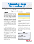
Figure 2. Gummel plot data.
Figure 1. FT_CE routine measurement setup screen.
Call for Questions
In order to solve this issue, the "VBE,VCE constant" or
"VBE, VCB constant" measurement sweep modes were
developed for the FT_CE routine. If one of these modes
are selected, the FT_CE routine will search for the bias
currents within the previously measured DC "bias" files.
These "bias" files contain the gummel (IC and IB data)
plot data. (Figure 2.) The gummel plot data is automatically
stored in a file named "bias.xxx" when data is measured,
July 2002
If you have hints, tips, solutions or questions to contribute, please
contact our Applications and Support Department
Phone: (408) 567-1000
Fax: (408) 496-6080
e-mail: [email protected]
Hints, Tips and Solutions Archive
Check our our Web Page to see more details of this example
plus an archive of previous Hints, Tips, and Solutions
www.silvaco.com
Page 17
The Simulation Standard
Your Investment in Silvaco is
SOLID as a Rock!!
While others faltered, Silvaco stood SOLID
for 15 years. Silvaco is NOT for sale and will
remain fiercely independent. Don’t lose
sleep, as your investment and
partnership with Silvaco will only grow.
SILVACO
CONTACTS:
I N T E R N AT I O N A L
Silvaco Japan
[email protected]
USA HEADQUARTERS
Silvaco Korea
[email protected]
Silvaco International
4701 Patrick Henry Drive
Building 2
Santa Clara, CA 95054
USA
Phone:
Fax:
408-567-1000
408-496-6080
[email protected]
www.silvaco.com
Silvaco Taiwan
[email protected]
Silvaco Singapore
[email protected]
Silvaco UK
[email protected]
Silvaco France
[email protected]
Silvaco Germany
[email protected]
Products Licensed through Silvaco or e*ECAD