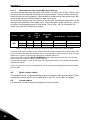
1
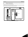
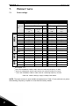
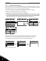
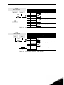
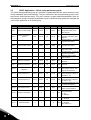
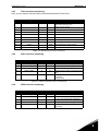
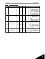
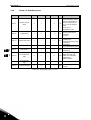
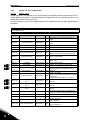
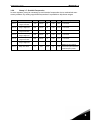
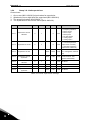
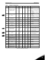
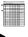
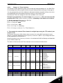
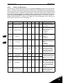
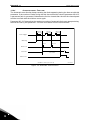
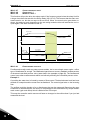
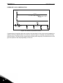
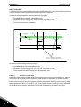
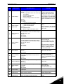
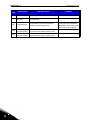
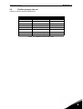
Honeywell • 59
M3.3.9
HVAC APPLICATION
PRESET FREQUENCY MODE
You can use the preset frequ ency parameters to define ce rtain frequency references in a dvance. These references are then applied by activating/inactivating digital inputs connected to
parameters M3.5.1.18, M3.5.1.19 and M3.5.1.20 ((Preset frequency selection B0, Preset frequency selection B1 and Preset frequency selection B2). Two different logics can be selected:
Selection
number
Selection name
Note
0
Binary coded
1
Number (of inputs used) According to how many of the inputs assigned for Preset frequency selections are active you can apply the Preset frequencies 1 to 3.
M3.3.10 TO
M3.3.17
Combine activated inputs according to Table 48 to choose the
Preset frequency needed.
PRESET FREQUENCIES 1 TO 7
The values of the preset frequencies are automatically limited between the minimum and maximum frequencies (M3.3.1 and M3.3.2). See table below.
Required action
Activated frequency
Choose value 1 for parameter M3.3.3
Preset frequency 0
B2
B1
B0
Preset frequency 1
B2
B1
B0
Preset frequency 2
B2
B1
B0
Preset frequency 3
B2
B1
B0
Preset frequency 4
B2
B1
B0
Preset frequency 5
B2
B1
B0
Preset frequency 6
B2
B1
B0
Preset frequency 7
Table 48. Selection of preset frequencies;
M3.4.1
= input activated
RAMP 1 SHAPE
The start and end of acceleration and deceleration ramps can be smoothed with this parameter. Setting value 0 gives a linear ramp shape which causes acceleration and deceleration to
act immediately to the changes in the reference signal.
Setting value 0.1…10 seconds for this parameter produces an S-shaped acceleration/deceleration. The acceleration time is determined with parameters M3.4.2 and M3.4.3. See Figure 9.
These parameters are used to reduce mechanical erosion and current spikes when the reference is changed.
3