1
Freescale Semiconductor, Inc.SSI Programming Model
ARCHIVED BY FREESCALE SEMICONDUCTOR, INC. 2005
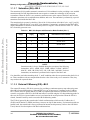
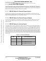
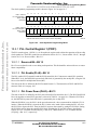
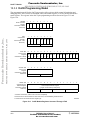
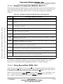
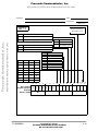
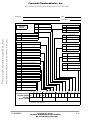
8.2.8.12 SSI Enable (SSIEN)—Bit 4
The SSI enable (SSIEN) control bit enables and disables the SSI. If the SSIEN bit is set, the SSI is enabled,
which causes an output frame sync to be generated when set up for internal frame sync, or causes the SSI
to wait for the input frame sync when set up for external frame sync. If the SSIEN bit is cleared, the SSI is
disabled. When disabled, the STCK, STFS, and STFS pins are tri-stated, the status register bits are preset
to the same state produced by the DSP reset, and the control register bits are unaffected.
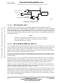
8.2.8.13 Network Mode (NET)—Bit 3
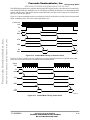
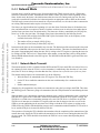
The network mode (NET) control bit selects the operational mode of the SSI. When the NET bit is cleared,
normal mode is selected. When the NET bit is set, network mode is selected.
ARCHIVED BY FREESCALE SEMICONDUCTOR, INC. 2005
Freescale Semiconductor, Inc...
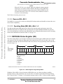
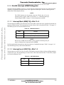
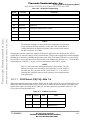
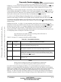
8.2.8.14 Frame Sync Invert (FSI)—Bit 2
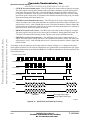
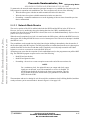
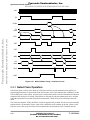
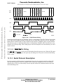
The frame sync invert (FSI) control bit selects the logic of frame sync I/O. If the FSI bit is set, the frame
sync is active low. If the FSI bit is cleared, the frame sync is active high.
8.2.8.15 Frame Sync Length (FSL)—Bit 1
The frame sync length (FSL) control bit selects the length of the frame sync signal to be generated or
recognized. If the FSL bit is set, a one-clock-bit-long frame sync is selected. If the FSL bit is cleared, a
one-word-long frame sync is selected. The length of this word-long frame sync is the same as the length of
the data word selected by WL[1:0].
8.2.8.16 Early Frame Sync (EFS)—Bit 0
The early frame sync (EFS) control bit controls when the frame sync is initiated for the transmit and
receive sections. When the EFS bit is cleared, the frame sync is initiated as the first bit of data is
transmitted or received. When the EFS bit is set, the frame sync is initiated 1 bit before the data is
transmitted or received. The frame sync is disabled after one bit-for-bit-length frame sync and after one
word-for-word-length frame sync.
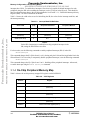
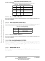
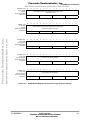
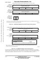
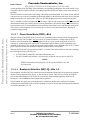
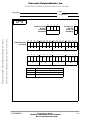
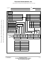
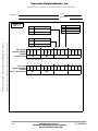
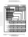
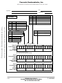
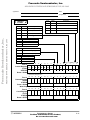
8.2.9 SSI Control/Status Register (SCSR)
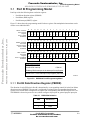
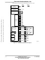
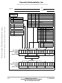
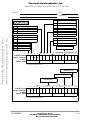
The SSI control/status register (SCSR) is a 16-bit register used to set up and monitor the SSI. The top half
of the register (bits 15–8) is the read/write portion and is used for SSI setup. The bottom half of the register
(bits 7–0) is read-only and is used by the DSP56824 to interrogate the status and serial input flags of the
SSI. The control and status bits are described in Section 8.2.9.1, “Reserved Bit—Bit 15,” through
Section 8.2.9.15, “Transmit Data Buffer Empty (TDBE)—Bit 0.” See Figure 8-6 on page 8-7 for the
programming models of the SCSR.
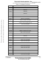
NOTE:
All the flags in the status portion of the SCSR are updated after the first bit
of the next SSI word has completed transmission or reception. Some status
bits (ROE and TUE) are cleared by reading the SCSR followed by a read
or write to either the SRX or STX register. Because of this, the control bits
in the top half of the SCSR should only be read when the SSI is disabled
(SSIEN = 0).
Synchronous Serial Interface
For More Information On This Product,
Go to: www.freescale.com
8-15