1
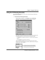
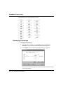
7
Using the Traffic Cop
In this chapter
Traffic Cop overview 194
Using the Traffic Cop 195
800 Series Traffic Cop 199
Quantum Traffic Cop 205
Micro 300 Series Traffic Cop 212
900 Series Traffic Cop 215
A120 Series Traffic Cop 215
Momentum M1 I/O systems 216
Using the I/O Drawing Generator 219
ProWORX NxT User’s Guide
Traffic Cop overview
The Traffic Cop is used to configure the I/O drops, racks, and slots. Often,
more than one Traffic Cop series can be configured in your database.
For example, you can have a 800 Series drop, a DCP Series drop, and a 900
Series drop configured in the same database. A120 and Micro Series devices
are exceptions.
Drops, racks, and slots
Your Modicon control system involves a certain amount of Discrete and
possibly Analog I/O (Input/Output). Each I/O point is physically wired to a
terminal of an I/O card in a rack somewhere on your plant floor.
Modicon I/O can be set up either locally (attached directly to the backplane of
the main controller rack) or as Remote I/O (through the use of a Remote I/O
processor in the main controller rack.) Remote I/O, though not supported by
all controller types, allows the greatest flexibility and capacity for your system.
I/O is serviced by the controller in groups called drops (or channels). A single
drop of I/O can consist of multiple racks of I/O and must be scheduled to be
scanned (in the Segment Scheduler) during the controllers’scan of the logic.
For controllers with local I/O, it is always drop #1.
Remote drops of I/O communicate with the main controller through a Remote
I/O processor in the main controller’s rack. Several I/O families exist for
Modicon 984/584 controllers.
194
l Traffic Cop overview
Chapter 7 Using the Traffic Cop
Using the Traffic Cop
The tree control area of the Traffic Cop window lets you select different drops
(or racks within drops) in the Traffic Cop tree.
Ø To display the Traffic Cop:
Ÿ From the Network Editor, on the Configuration menu, click Traffic
Cop or click
on the toolbar.
The tree provides a
hierarchical view of
configured drops and
racks. Select a drop or
rack to see its configuration.
Ø To navigate through a tree:
Ÿ Click
to move up one visible row in the tree.
Ÿ Click
to move down one visible row in the tree.
Ÿ Click
to move up one level in the tree (for example, from a rack up
to its parent drop.
Ÿ To expand the racks in a drop, click
Ÿ To collapse the racks in the drop, click
Ÿ To select a drop
or rack
to the left of the drop.
to the left of the drop.
, click on it.
Using the Traffic Cop l 195
ProWORX NxT User’s Guide
Using the Traffic Cop data display
The Data Display window is available only in the 200, 900, and DCP series
Traffic Cop. It shows a list of all programmed references and data.
Ø To display the programmed references and data:
Ÿ From the Traffic Cop window, click Data. The Data Display window
appears.
Discretes are displayed as ON or OFF (DON, DOFF if disabled) and registers are
displayed in the selected Radix.
196
l Using the Traffic Cop
Chapter 7 Using the Traffic Cop
Auto addressing in the Traffic Cop
The Auto Address function lets you set default addresses to be entered when
programming a new card into Traffic Cop. The addresses are automatically
incremented for each new card added.
Ø To set the default addresses for new cards:
1.
From the Traffic Cop window, click Auto Addressing. The Auto
Addressing window appears.
2.
For each reference type (0xxxx, 1xxxx, 3xxxx, 4xxxx), type the default
starting address.
3.
Click Last Used to recalculate the next available address for a Traffic
Cop card. This prevents duplicate addresses from being used.
4.
Click OK.
Displaying the terminal block (800, Quantum, A120)
The Terminal Block dialog box displays the card currently selected, with
programmed references, data values, symbols (if selected) and their
descriptors. If Symbols are turned on in Preferences, then an additional
column containing all the symbols is displayed.
If you’re working Online, I/O points are monitored and updated.
Using the Traffic Cop l 197
ProWORX NxT User’s Guide
Ø To display the terminal block for a programmed card:
1.
In the Traffic Cop, click the card you want to display.
2.
Click Terminal. The Terminal Block window appears with the
location (drop, rack, slot) of the selected card displayed in the title bar.
Ÿ Next: Click to display the terminal block of the next card in the
currently selected rack.
Ÿ Prev: Click to display the terminal block of the previous card in the
currently selected rack.
Ÿ Doc: Click to edit the documentation for the currently selected
address in the Doc Editor.
Ÿ Goto: Click to search for an address in logic that corresponds with
the I/O point. If a match is found, you can exit the Traffic Cop and
go directly to the Network Editor, where a complete address search
of the logic is performed.
Configuring a drop
If a drop has not been configured yet, Configure is displayed in the drop
overview area. The Traffic Cop tree control cannot be expanded until the drop
type has been chosen.
Ø To configure a drop:
198
1.
Click the drop in the tree control.
2.
Click Configure. The Drop Configuration dialog box appears with the
previous default selections.
3.
Select the interface corresponding to your topology.
4.
Click OK.
l Using the Traffic Cop
Chapter 7 Using the Traffic Cop
800 Series Traffic Cop
This Traffic Cop is used to configure an 800-series drop.
Racks associated with the drop (and the cards configured in the racks) are also
displayed to the right of the tree control. The racks can be displayed in two
views and both allow you to edit slots:
Ÿ Drop Edit: Displays all racks in the drop.
Ÿ Rack Edit: Zooms in to display only the currently selected rack. This
view also lets you configure the rack type and size.
Ø To configure an 800 Series drop:
1.
From the Traffic Cop tree control, select the 800 Series drop to edit.
NxT displays the Edit Drop view in the right side of the window.
2.
In Hold Up Time, type the number of seconds for this I/O drop to
hold its I/O values if communication from the 984 is lost.
3.
In ASCII Port, type the ASCII Port used for ASCII messaging on this
drop.
If the racks haven’t been configured for the drop yet, click Configure and select
an interface, then click OK to continue.
Ø To insert a slot, rack, or drop:
1.
From the Traffic Cop window, click Insert. NxT displays the Insert
Traffic Cop Item window.
2.
Select the item to insert.
3.
Click where it should be placed:
Ÿ Insert before: The currently-selected item is shifted right if it is a
slot or down if it is a rack or a drop.
Ÿ Insert after: Items after or below the currently selected item are
shifted right or down.
You can press the INSERT and DELETE keys to insert or delete heads, drops,
racks, or slots.
800 Series Traffic Cop l 199
ProWORX NxT User’s Guide
Ø To clear or delete a slot, rack, or drop:
1.
From the Traffic Cop window, select the item to delete.
2.
Click Delete. NxT displays the Delete Traffic Cop Item window.
3.
Select whether you are deleting a slot, rack, drop, or all drops in the
Traffic Cop.
4.
Select an action, then click OK.
Ÿ Delete: Removes the item, shifting the remaining items up (rack or
drop) or left.
Ÿ Clear: Clears the item and leaves it empty, without shifting
neighboring items.
You can press the INSERT and DELETE keys to insert or delete heads, drops,
racks, or slots.
Ø To move a card from one slot to another:
Ÿ Drag the card from its current slot to the destination slot.
Ø To edit a slot:
1.
From the Traffic Cop display, select a slot and click Edit or doubleclick the slot. The Slot Edit window appear.
Selecting a card displays the
power supply loading and
mechanical keying for the
card. Select a card from the
drop-down list, then click OK.
2.
200
Select the card to insert in the slot (selected in the Traffic Cop window)
from the drop-down list. Selecting a card displays the power supply
loading and mechanical keying for the card.
l 800 Series Traffic Cop
Chapter 7 Using the Traffic Cop
3.
In the address field (In or Out), type the starting address for the
address range assigned to this card, then click OK.
For example, suppose you are configuring a B828 card with 16
outputs. The address field will be entitled Out and you must type the
initial address of a 16 address table (0xxxxx) for this card. The final
address in the table is automatically displayed.
The table must begin on a word boundary. If a starting address that is not on a
word boundary (16+1) is used, NxT automatically adjusts the address to the
nearest boundary. The address table is automatically provided if you have
selected Auto Addressing.
Some cards have other values which are configured at this level.
Selecting a B863-001 (4 Channel In). For example, lets you toggle
between BIN and BCD.
800 Series Traffic Cop l 201
ProWORX NxT User’s Guide
DCP Series Traffic Cop
The DCP Series Traffic Cop is a four-page display showing the addresses used
to transfer data to and from a D908 tied to an S908 system. The D908 is a
distributed control processor available for 680/685/780/785 systems. The
controllers use a D908 for a remote drop to the master S908 system.
Ø To edit DCP drops:
1.
From the Network Editor, on the Configuration menu, click Traffic
Cop or click
in the Toolbar.
The four pages of the drop are displayed as racks in the tree control as racks.
Selecting a rack from the tree control displays the corresponding page, where
you can edit individual slots.
2.
Click the corresponding button of the Page you want to configure (for
example, click
to configure Page #3). The Traffic Cop display
switches to Edit Rack mode, showing the slots for a single page.
202
l DCP Series Traffic Cop
Chapter 7 Using the Traffic Cop
Ÿ The HB field displays the health status for each slot: OK appears if
the card is fine or ?? appears if the card is unhealthy.
Ÿ To view data for a local address table, select the table and click
Data.
Ÿ To type or edit documentation for a slot, select the slot and click
Doc.
3.
Double-click the slot to configure or select the slot and click Edit.
4.
Double-click Local Address, or select it and click Edit. The slot edit
dialog box is displayed. The location of the currently selected slot is
displayed in the Title Bar in the format Drop/Rack/Slot.
5.
In Address, type the starting address for the Local Address table.
DCP Series Traffic Cop l 203
ProWORX NxT User’s Guide
In a DCP system, registers are automatically exchanged between the
supervisory PLC and the distributed control drop. The supervisory
PLC writes 0xxxx or 4xxxx information to the distributed drop and
reads 1xxxx or 3xxxx information from the distributed drop. This step
sets the registers to be used for the exchange.
6.
In Length, type the length (in words) of the Local Address table.
ProWORX NxT automatically sets the remote address to the length
corresponding to the word length entered for the Local Address.
Addresses 300001 and 300002 are reserved for the Option State and
Write Count, respectively.
7.
204
Click OK.
l DCP Series Traffic Cop
Chapter 7 Using the Traffic Cop
Quantum Traffic Cop
Quantum I/O can be set up for Local I/O or Remote I/O (RIO). In addition,
Distributed I/O (DIO) is controlled via the Modicon Modbus Plus network.
Like other Modicon I/O, Quantum I/O is organized based on drops and racks.
However, in addition to drop number and rack number, Quantum I/O
devices also have a head number. Since Quantum controllers can have up to
four I/O systems (one RIO and three DIO), each I/O system is given a head
number. The head number is the slot where the card is located on the local rack
where the I/O system is connected.
DIO drops connected to a
DIO processor occupying
Head 2 (slot 2) of the local
Quantum backplane. All of
those drops belong to
Head 2.
The DIO drop connected to
the CPU, which is in the
sixth slot of the 6 slot backplane is designated as
Drop 64, Head 6.
Ø To configure the Quantum Series Traffic Cop:
1.
In the Traffic Cop tree control, select the Quantum Series drop to edit.
NxT displays the Edit Drop display in the right side of the window.
2.
In Hold Up Time, type the amount of time (in seconds) for this I/O
drop to scan its I/O if communication from the 984 is lost.
3.
In ASCII Port, type the ASCII Port used for ASCII messaging on this
drop.
If the racks haven't yet been configured for the drop, click Configure and select
an interface, then click OK to continue.
Quantum Traffic Cop l 205
ProWORX NxT User’s Guide
3xxxx Status Register
When using the Quantum Series Traffic Cop, you can set a 3xxxx Status
Register for your drop.
Ø To set the 3xxxx Status Register:
1.
In the Status area of the Traffic Cop window, click Edit. The Quantum
Drop Status dialog box appears.
2.
Type the register to store the controller status bits, then click OK.
If you are using the Quantum Series Traffic Cop and you are using Distributed
I/O (DIO), you can set the directions in which 3xxxx status register
information travels. To activate the DIO Read/Write Status, on the tree
control, click the appropriate distributed drop.
Ø To set the read/write status:
1.
In the Status area of the Traffic Cop window, click Edit. The Quantum
Drop Status dialog box appears.
2.
Select one of the following, then click OK:
Ÿ Read/Write Drop: Data is passes both to and from the drop and the
DIO processor.
Ÿ Read Only Drop: Data is passed only from the drop to the DIO
processor.
206
l 3xxxx Status Register
Chapter 7 Using the Traffic Cop
Ø To insert a slot, rack, or drop:
1.
In the Traffic Cop dialog box, click Insert. NxT displays the Insert
Traffic Cop Item dialog box.
2.
Select the item to insert and where it should be placed:
Ÿ Insert before: Currently selected item is shifted right (slot) or down
(rack or drop).
Ÿ Insert after: Items after (below) the currently selected item are
shifted.
You can press the INSERT and DELETE keys to insert or delete heads, drops,
racks, or slots.
Ø To clear or delete a slot, rack, or drop:
1.
In the Traffic Cop dialog box, select the item to delete.
2.
Click Delete. NxT displays the Delete Traffic Cop Item dialog box.
3.
Select whether you’re deleting a slot, rack, drop, or all drops in the
Traffic Cop.
4.
Select an action, then click OK:
Ÿ Delete: Removes the item, shifting the remaining items up (rack or
drop) or left.
Ÿ Clear: Clears the item and leaves it empty, without shifting
neighboring items.
Ø To edit a slot:
1.
Select the slot to edit, then click Edit or double-click the slot to edit.
The Slot Edit window appears with a list of available cards.
2.
Select the card to insert in the slot (selected in the Traffic Cop window)
from the drop-down list. Selecting a card displays the power supply
loading and mechanical keying for the card.
3.
In the address field (In or Out), type the starting address for the
address range assigned to this card, then click OK.
For example, if you are configuring a DAI340-00 card with 16 inputs.
In the IN address field, type the initial address of a 16 address table
(1xxxxx) for this card. The last address in the table is displayed.
3xxxx Status Register l 207
ProWORX NxT User’s Guide
For some cards, the table must begin on a word boundary. If you type a starting
address that is not on a word boundary (16+1), NxT automatically adjusts the
address down to the nearest boundary. The address table is automatically
provided if you have selected Auto Addressing.
Some cards have other values which are configured at this level.
Selecting a MSB101-00 (Motion Inc Enc). For example, to toggle
between BIN and BCD.
Configuring the CPU for a particular slot
If the CPU isn’t configured in the Traffic Cop and you’re offline, you’re
prompted with the CPU Not in Traffic Cop dialog box. You can choose
between slots 1 through 16 or configure the CPU later.
Configuring Quantum cards
Most Quantum cards require additional parameters to configure.
Ø To configure card-specific options:
208
1.
From the Quantum Traffic Cop, select the card to configure.
2.
Click Card Config. The Card Configuration dialog box appears.
3.
Type or select the card-specific parameters, then click OK. Consult the
card’s manual for details. For example, Setting up an Interbus-S
NOA611-00 Card in the Quantum Traffic Cop
l Configuring the CPU for a particular slot
Chapter 7 Using the Traffic Cop
Working with NOA611-00 cards
ProWORX NxT supports Interbus-S I/O devices through a Quantum
NOA611-00 Card. NxT communicates with a Quantum controller, which
relays information to and from the NOA611-00. The card then receives data
and transmits instructions to the Interbus-S I/O devices. Set up the NOA61100 card through the Quantum Traffic Cop.
Ø To set up an NOA611-00 card:
Before continuing, you must have configured your database for a Quantum
controller (see Controller configuration - Controller tab on page 66).
1.
From the Network Editor, on the Configuration menu, click Traffic
Cop or click
in the toolbar. The Quantum Traffic Cop appears.
Example: To place an
NOA611-00 card, select
the local drop and the slot
where it will be placed, then
click NOA611 on the IO
Adpt menu.
You can also select a slot,
click Edit, then choose the
NOA611-00 from the dropdown list.
2.
In the Traffic Cop window, click the Quantum Series local drop to
select it. The NOA611-00 must be placed in a local drop. Note that the
drop must be configured before you can place items into it.
v For instructions on configuring a drop, see Configuring a drop on
page 198.
3.
Click the slot where the NOA611-00 will be placed to select it.
Configuring Quantum cards l 209
ProWORX NxT User’s Guide
4.
Click IO ADAPT, then click NOA611-00. The NOA611-00 icon
appears in the slot.
5.
Double-click the NOA611-00 icon or with the NOA611-00 icon
selected, click the lower Edit. The Slot Edit dialog box appears.
6.
Edit the NOA611-00 settings as necessary, then click OK.
Ÿ For both In and Out, type an initial address for the range assigned
to the card. NxT provides an address table automatically.
Ÿ Click either BIN (Binary) or BCD (Binary-Coded Decimal). See
your NOA611-00 user’s manual for more information.
7.
Click Card Config.
8.
Configure the Output Timeout State according to the NOA611-00
user’s manual, then click OK. The Card Configuration window closes.
9.
To close the Traffic Cop, click OK.
Working with cards on an AS-I network
ProWORX NxT supports AS-I devices through an Quantum AS-I Card. NxT
communicates with a Quantum controller, which relays information to and
from the AS-I card. The card then receives data and transmits instructions to
the AS-I devices.
Ø To see address descriptions for an AS-I card:
210
1.
From the Quantum Traffic Cop, select the AS-I card you want.
2.
Click Card Status. The AS-I Device List appears.
l Configuring Quantum cards
Chapter 7 Using the Traffic Cop
Ø To view a list of AS-I devices for an AS-I card:
1.
With an AS-I card selected, from the Quantum Traffic Cop, click Card
Status
- Or From the Network Editor panel, click Status. The AS-I Device list
appears.
You can doubleclick in the Profile,
Parameter, or LPS
columns to configure a specific
slave.
You can type a description for any device
in the Device Name
column. This description is stored with the
database.
Below are the options from the AS-I Device List:
Ÿ Data: Click to display the Register Editor dialog box. You may also
double-click in either the I/P Address column or the O/P Address
column to display the Register Editor dialog box.
Ÿ Card Config: Click to display the card configuration information
for the AS-I card
Ÿ Print: Click to print the AS-I Device List.
Ÿ Slave Edit: Click to configure a specific slave.
The Card Config and Slave Edit buttons are unavailable if you are launching
the AS-I Device List from the Network Editor or when the controller is running.
Configuring Quantum cards l 211
ProWORX NxT User’s Guide
Micro 300 Series Traffic Cop
The Micro Drop Summary displays a summary of configured I/O modules.
Each drop in the Micro Traffic Cop is described as single, parent, or child.
Micro 512 and 612 Series
controllers can have A120
Series I/O cards programmed in racks 2 to 4.
Ø To edit a slot:
1.
From the Micro Traffic Cop, select the slot to edit and click Edit or
double-click the slot. The Edit window appears.
2.
In the Card field, select the card to insert in the slot. Selecting a card
displays the power supply loading and mechanical keying for it.
3.
In the address (In or Out), type the starting address for the address
range assigned to this card, then click OK.
For example, if you configure a B828 card with 16 outputs, the address
field is entitled Out. You must type the initial address of a 16 address
table (0xxxxx) for this card. The final address in the table is displayed.
For some cards, the table must begin on a word boundary. If starting address us
used that isn’t on a word boundary (16+1), the address is adjusted to the nearest
boundary. The address table is provided when Auto Addressing is selected.
Some cards have other values which are configured at this level.
Selecting a MIC141 (4 Channel In/2 Channel Out). For example, lets
you toggle between BIN and BCD.
212
l Micro 300 Series Traffic Cop
Chapter 7 Using the Traffic Cop
200/500 Series Traffic Cop
The 200/500 Series I/O screen is an S908 representation of the connection to a
J290/J291 interface device. The 200 Series drop contains racks 2 to 5. For each
slot in the rack, NxT displays the slot number, type (input or output), reference
address range (the associated addresses in logic), data type (discrete or
analog), and the health status (OK or ??) of the card. The health status is only
available if the controller is running and channels are not explicitly displayed.
Ø To configure a slot:
1.
Select the drop and rack containing the slot you want to edit from the
tree control. The rack appears in the Edit Rack area of the window.
2.
Select the slot to edit and click Edit or double-click the slot.
3.
Type the first address of the table associated with this input or output
point, then click OK.
For example, suppose you are entering an address table for a 16 IN slot
on a J290. You must associate this slot with a 16-bit table of discretes,
or one 16-bit register.
If you are entering a register, select the input type (binary or BCD).
Below are some of the other features you can use in the Traffic Cop:
Ÿ Data: Click to view the address contents (the register value or the
state of each discrete in the table).
Ÿ Doc: Click to edit documentation for each slot.
Ÿ Insert: Click to delete an item (slot, rack, or drop) from the Traffic
Cop.
Ÿ Auto Addressing: Click to set the default addresses for new cards
configured into the Traffic Cop. NxT automatically increments the
addresses for each new card configured.
Micro 300 Series Traffic Cop l 213
ProWORX NxT User’s Guide
200/500 Series slot edit
Ø To configure a slot:
1.
Select the drop and rack containing the slot you wish to edit from the
tree control. The rack is displayed in the Edit Rack area of the
window.
2.
Select the slot to edit and click Edit, or double-click the slot.
3.
Type the first address of the table associated with this input or output
point.
For example, suppose you are entering an address table for a 16 IN slot
on a J290. You must associate this slot with a 16-bit table of discretes,
or one 16-bit register.
If you are entering a register, enable the input (binary or BCD).
4.
214
Click OK.
l 200/500 Series slot edit
Chapter 7 Using the Traffic Cop
900 Series Traffic Cop
The 900 Series I/O displays the Traffic Cop screen for a motion control I/O
drop. The Traffic Cop allows a bi-directional 8 register slot for data transfer. A
900 Series drop is always a remote drop and only found in conjunction with an
S908 remote I/O processor. If the controller is running, NxT Online displays
the controller health status (OK or ??) in the HB field.
Ø To edit a slot:
1.
In the tree control, select the drop to edit. NxT displays the single slot
for the drop, the card entered (if any), as well as the input and output
reference numbers, data type, and description of the card.
2.
Select the slot and click Edit, or double-click the slot. NxT displays the
Edit dialog box, with the drop, rack, and slot shown in the title bar.
3.
In Input, type the starting register reference number.
4.
In Output, type the starting register reference number.
5.
Click the proper Data Type (binary or BCD).
6.
Click OK.
A120 Series Traffic Cop
This Traffic Cop Series is used with A series compact and new Micro series
controller.
The Slot Edit function for the A120 Series Traffic Cop allows you to edit a
configured card or type a new card into a slot.
Ø To edit the card:
1.
Click the
to the right of the card entry box. A list of valid cards for
the drop type you are using appears.
2.
Select a card from the drop down list.
3.
In Input (or Output), type the starting address of the address table
associated with the I/O points on this card.
900 Series Traffic Cop l 215
ProWORX NxT User’s Guide
Momentum M1 I/O systems
Momentum I/O systems differ from those of other Modicon controllers. A
Momentum I/O system grows from a single Momentum I/O base unit. An M1
Processor Adapter (for example, a controller) is mounted on a Momentum I/
O base. If a Momentum Option Adapter is used, it is mounted between the
Processor Adapter and the I/O base.
Option Adapter
(optional)
Processor Adapter
(controller)
Momentum I/O base card
Option Adapters add a time of day clock and one or two additional Modbus
ports, depending on the Adapter model. Features of an Option Adapter are
configured along with the Processor Adapter; as far as controller configuration
is concerned, the division between the two is transparent.
I/OBus
The M1 760-00, M1 760-10 and M1 960-20 Processor Adapters also provide a
way to control a network of Interbus-S cards over an I/OBus. The M1 760-00,
M1 760-10 or M1 960-20 becomes a master on the Interbus network. Slave
devices on a network of this type can be standard Interbus cards (including
Modicon cards configured for Interbus communications) or Momentum I/O
bases with Interbus Communication Adapters mounted on them.
M1 760-00, M1 760-10,
M1 960-20
controllers (master)
Interbus-compatible
devices (slaves)
In an I/OBus, each Interbus-S card is connected to its neighbor in a string.
Signals are passed from one card to the next card in line. Node addresses are
based on a card’s virtual position in the I/OBus network.
216
l Momentum M1 I/O systems
Chapter 7 Using the Traffic Cop
The first card connected to the I/OBus master (the M1 760-00, M1 760-10 or M1
960-20) has an address of 1. Subsequent cards are numbered 2, 3, and so on. A
maximum of 128 cards for the M1 760-00 and 256 cards for the M1 760-10 and
M1 960-20 can be on your I/OBus network.
M1 Traffic Cop
The I/O base
Cards on the I/OBus
The main window of the M1 Traffic Cop lists all modules currently inserted
into the Momentum network. For the M1 700/780-00, M1 700-10, M1 780-10
and M1 980-20 controllers, there is only a single entry, the LCL or LoCaL node.
This is the I/O base onto which the controller is mounted.
With the M1 760-00, M1 760-10 and M1 960-20 controllers, you can also add
Interbus-S cards in a string of nodes (that is, slots) called the I/OBus. These can
be Modicon cards configured for Interbus communications, other Momentum
I/O bases with an Interbus adapter, or third-party Interbus-S cards.
Ø To view the configuration of a particular slot:
Ÿ From the Momentum Traffic Cop, either double-click the slot or select
the slot and click Edit. The Slot Edit dialog box appears.
The LCL, or LoCaL node, is the I/O base onto which the M1 controller
is mounted. When using any of the M1 700/780-00, M1 700-10, M1
780-10 or M1 980-20 controllers. Only this node can be configured.
When selecting a node on an I/O Bus connected to a M1 760-00, M1
760-10 or M1 960-20 controller, you can only select slots greater than
one if a card exists for all previous slots in the string. For example, you
can only add a card into slot 3 if cards have already been added for
slots 1 and 2.
M1 Traffic Cop l 217
ProWORX NxT User’s Guide
Ø To add a card to the I/OBus:
1.
From the Traffic Cop, select the card in the position following the one
where the new card will be inserted. To add a card to the end of the
I/O Bus, select the blank line following the last card on the list.
2.
Click Insert. The Slot Edit dialog box appears.
3.
Configure the slot card as described in the following instructions.
Ø To configure a slot card in the Slot Edit dialog box:
1.
If necessary, in the Card box, select the card for this slot.
If you are configuring cards in slots other than the LCL (LoCaL) node,
this list will include supported Interbus-S cards. Otherwise, you will
only be able to insert Momentum I/O bases.
2.
In the address boxes (IN and OUT), type the starting address for the
address range assigned to this card. If Auto Addressing is turned on,
a set of address ranges are selected for you automatically.
For example, if you configure an ADI540-00, a Discrete Input card
with 16 inputs. In the IN field, type the initial address of a 16-address
table (1xxxxx) for this card. The final address is calculated.
On some cards, the initial address for a table of I/O points must begin on a word
boundary. That is, it must be one more than a multiple of 16, like 300001 or
100017. If you type a starting address that is not on a word boundary, NxT will
adjust the address down to the nearest boundary.
3.
If necessary, click BIN or BCD, depending on how the integer value is
stored. BIN indicates straight binary representation and BCD
indicates Binary-Coded Decimal.
4.
Click OK.
To replace the card within a particular slot, use the Traffic Cop card menus. Click
the slot you want to replace, then select a card from the Base Modules,
Modicon Ibus and Generic Ibus menus at the top of the Traffic Cop dialog box.
218
l M1 Traffic Cop
Chapter 7 Using the Traffic Cop
Using the I/O Drawing Generator
The I/O Drawing Generator is used to create CAD drawings of 800, Micro,
Quantum and A120 I/O.
Ø To activate the I/O Drawing Generator:
Ÿ From the Network Editor, on the Display menu, I/O Drawing
Generator. The I/O Drawings Generator dialog box appears.
The Traffic Cop default setting for the drawings is Intermediate and
the default directories are those directories previously used.
Ÿ Click Browse to change the directories. The File Open dialog box
appears.
Ÿ Click Generate to generate the drawing.
There are different symbols you can use to represent real world
devices in your I/O drawings. Type these symbols into the descriptor,
starting with a dollar sign ($).
This is the descriptor field in the Documentation Editor.
Type symbols by preceding the symbol text with a $.
See below for a list of symbols and their corresponding
text. The symbol can be in any descriptor field.
Using the I/O Drawing Generator l 219
ProWORX NxT User’s Guide
The following is a list of all symbols you can use:
Displaying I/O drawings
Ø To display I/O drawings:
1.
From the Network Editor, on the Display menu, I/O Drawing
Generator. The I/O Drawing Generator dialog box appears.
2.
Click Display. The I/O Drawing Display dialog box appears.
.
Once the final .DXF drawings are created, they can be imported using
your CAD program.
220
l Displaying I/O drawings
Chapter 7 Using the Traffic Cop
Ø To pan across the drawing:
1.
Click Pan.
2.
Click at the location you want to be begin your pan view.
3.
Drag the cursor to another location in the drawing and release the
mouse button. The view pans from the start location to your end
location.
Ø To zoom into the display:
1.
Click Zoom.
2.
Click at the start location where you want to begin your zoom.
3.
Drag your cursor to mark the area. A rectangle appears to define the
section of drawing you want to zoom in on.
4.
Release the mouse button.
Ø To zoom out of the display:
Ÿ Click Zoom Out.
Ø To select a different .DXF drawing:
1.
From the I/O Drawing Display window, click Open. The File Open
dialog box appears.
2.
Select the .DXF to display, then click OK.
Ø To print a drawing:
Ÿ From the I/O Draw Display window, click Print. The drawing is
printed to your default printer.
Displaying I/O drawings l 221