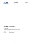
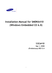
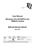
1
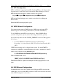
Windows Embedded CE 6.0 BSP for the HawkBoard Quick Start Guide MPC Data Limited Revision: Issue 2 Date: 7 June, 2010 Reference 2903-UD01 Approved: Windows Embedded CE 6.0 BSP for the HawkBoard – Quick Start Guide Page 1 All trademarks are hereby acknowledged Copyright 2010 MPC Data Limited Document Change History Revision Date Author Comment Draft 1a 11 March 2010 Rik Attrill Initial draft, seeded from “TI Win CE 6.0 BSP for OMAP-L138 - Quick Start Guide” (2854-UD01), Draft 3a, Mike Wyatt. Draft 1b 15 March 2010 Rik Attrill Updated after review by Garry Clarkson Draft 1c 15 March 2010 Rik Attrill Update after more minor changes Issue 1 15 March 2010 Rik Attrill Draft 1b Approved as Issue 1 Draft 2a 02 June 2010 Rik Attrill Updated to include TFTP downloader tool, and more detail for the v1.0 release (full and evaluation versions). Draft 2b 07 June 2010 Rik Attrill Updated after review by Garry Clarkson Issue 2 07 June 2010 Rik Attrill Draft 2b approved as Issue 2 MPC Data Limited Issue 2, 07 June 2010 Windows Embedded CE 6.0 BSP for the HawkBoard – Quick Start Guide Page 2 Table Of Contents 1. Introduction ....................................................................................... 4 2. Scope ................................................................................................. 4 2.1 Full BSP Source Release ................................................................................. 4 2.2 Evaluation Release .......................................................................................... 4 3. References ......................................................................................... 5 4. Requirements ..................................................................................... 6 4.1 Hardware ......................................................................................................... 6 4.2 Software .......................................................................................................... 6 5. Hardware Setup ................................................................................. 8 5.1 HawkBoard Setup ........................................................................................... 8 5.2 USB Hardware ................................................................................................ 8 5.3 Audio Hardware .............................................................................................. 9 5.4 SD/MMC Cards .............................................................................................. 9 5.5 Display Hardware ............................................................................................ 9 5.6 PWM Hardware............................................................................................... 9 5.7 UPP Hardware ................................................................................................. 9 5.8 NAND Hardware ............................................................................................. 9 6. Building the BSP ............................................................................. 10 6.1 Tools Setup.................................................................................................... 10 6.2 BSP Source Code Installation ....................................................................... 10 6.3 BSP Build Notes............................................................................................ 12 6.4 Building an OS Design .................................................................................. 12 7. Running OS Designs ....................................................................... 13 7.1 Flashing Eboot to NAND Flash .................................................................... 13 7.2 Configuring Eboot ......................................................................................... 16 7.3 Booting the Kernel ........................................................................................ 17 8. Customising An OS Design ............................................................ 22 8.1 CE 6.0 Catalog .............................................................................................. 22 8.2 OS Build Caveats .......................................................................................... 23 MPC Data Limited Issue 2, 07 June 2010 Windows Embedded CE 6.0 BSP for the HawkBoard – Quick Start Guide Page 3 8.3 BSP Component Conflicts ............................................................................ 23 8.4 KITL Configuration....................................................................................... 24 8.5 VMINI Network Configuration ..................................................................... 24 8.6 NDIS Ethernet Configuration ........................................................................ 24 8.7 Enabling the Remote Display ........................................................................ 25 8.8 Telnet and FTP Support ................................................................................ 26 8.9 USB Host Support ......................................................................................... 26 8.10 USB Function and ActiveSync Support ........................................................ 27 8.11 NAND Support .............................................................................................. 28 8.12 UART Support .............................................................................................. 28 8.13 SD/MMC File System Support ..................................................................... 29 8.14 Audio Support ............................................................................................... 29 9. Sample Applications ....................................................................... 31 9.1 Running Applications.................................................................................... 31 9.2 Audio Samples .............................................................................................. 31 9.3 VGA Display Samples .................................................................................. 31 9.4 I2C and SPI Samples ..................................................................................... 32 10. SDK ................................................................................................. 33 MPC Data Limited Issue 2, 07 June 2010 Windows Embedded CE 6.0 BSP for the HawkBoard – Quick Start Guide Page 4 1. Introduction This is the Quick Start Guide for the Windows Embedded CE 6.0 BSP for the HawkBoard platform. More information on this platform can be found in reference 2. For general information on the functionality and features provided in the BSP see the User Guide, reference 1. 2. Scope This revision of the Quick Start Guide describes the v1.0 release of the HawkBoard BSP produced by MPC Data. This document describes steps appropriate for both the full source code BSP and the ‘evaluation’ release which contains pre-built binaries only. 2.1 Full BSP Source Release This document describes how to install, build and configure the BSP source code, as well as how to deploy the built binaries onto a HawkBoard platform. Further information on Windows CE development can be found on the following Microsoft websites: Windows Embedded CE Developer Centre: http://msdn.microsoft.com/en-us/windowsembedded/ce/default.aspx Windows Embedded CE 6.0 Technical Documentation: http://msdn.microsoft.com/en-us/library/ee504799.aspx 2.2 Evaluation Release This document describes how to deploy the pre-built evaluation binaries onto a HawkBoard platform. Most of the sections in this document are applicable to the evaluation release, with the exception of sections 6 and 8 and 9. These sections rely on the BSP source code, which is not included with the evaluation release. For information about the configuration and functionality of the binaries included in the evaluation release, see the corresponding release note. MPC Data Limited Issue 2, 07 June 2010 Windows Embedded CE 6.0 BSP for the HawkBoard – Quick Start Guide Page 5 3. References 1. Windows Embedded CE 6.0 BSP for the OMAP-L13x, User Guide, 2854UD03, MPC Data Limited 2. HawkBoard User’s Manual, Revision 0.1 Preliminary. MPC Data Limited Issue 2, 07 June 2010 Windows Embedded CE 6.0 BSP for the HawkBoard – Quick Start Guide Page 6 4. Requirements 4.1 Hardware To use the BSP or binary image release, you will require the following hardware: • HawkBoard platform, available from various distributors: (http://www.hawkboard.org/distributors). • VGA LCD or CRT monitor (optional) • Development PC with the following minimum system requirements: o 1 GHz processor; 2 GHz recommended o 1 GB of RAM o Microsoft Windows XP Professional Service Pack 2 (English or Japanese recommended) or Windows Vista o 18 GB of available space required on installation drive o 1 GB of available space required on system drive o DVD-ROM Drive o Display monitor that supports 1024 x 768 high color or better o Keyboard and Microsoft mouse or compatible pointing device 4.2 Software This section lists the tools required for using the BSP and built images. 4.2.1 BSP development The following development tools and versions are required for building the BSP. Note: These tools are not required if using the pre-built evaluation binaries. • Microsoft Visual Studio 2005 Professional Edition • Microsoft Visual Studio 2005 Professional Service Pack 1 • Microsoft Visual Studio 2005 Professional SP1 Update for Vista (if applicable) • Windows Embedded CE 6.0 Platform Builder MPC Data Limited Issue 2, 07 June 2010 Windows Embedded CE 6.0 BSP for the HawkBoard – Quick Start Guide • Windows Embedded CE 6.0 Service Pack 1 • Windows Embedded CE 6.0 R2 • Windows Embedded CE 6.0 R3 • Windows Embedded CE 6.0 R3 Update Rollup (11/3/2009) • Windows Embedded CE 6.0 Monthly Updates (October onwards) Page 7 A Windows Embedded CE 6.0 Trial download is available from Microsoft: http://www.microsoft.com/windowsembedded/en-us/products/windowsce/default.mspx 4.2.2 Image Deployment The following tools are required to configure and deploy binary images onto the HawkBoard. Note: Some of the following software may be included with the HawkBoard BSP release (dependent on licensing restrictions). Check the release note for details. • Serial Terminal application (Tera Term Pro is recommended) • AISGen for D800K006 (http://www-s.ti.com/sc/techlit/sprab41.zip) • TFTP server (such as Tftpd32, http://tftpd32.jounin.net/) • Either of… o Windows CE BSP Development environment (described in section 4.2.1) o MPC Data CEDownload tool Note: The CEDownload tool implements functionality to download a Windows CE image via Ethernet, which is usually done using the Windows CE 6.0 development environment. However, the CEDownload tool is provided to allow quick evaluation of pre-built binaries, without requiring the full development installation. MPC Data Limited Issue 2, 07 June 2010 Windows Embedded CE 6.0 BSP for the HawkBoard – Quick Start Guide Page 8 5. Hardware Setup 5.1 HawkBoard Setup Set up the HawkBoard as described in section 2 of the User Guide supplied with the board (reference 2). The minimum set up required is: • Null-modem serial cable connected to the HawkBoard and the development PC • Ethernet cross over cable connected to the HawkBoard and the development PC (or both the HawkBoard and PC connected to a switch via standard Ethernet cables) • 5V power supply connected to the HawkBoard and the mains supply • SW1 DIP switches configured to boot from flash, as follows: 5.2 USB Hardware USB client devices such a mouse, keyboard or flash drive can be attached directly to the HawkBoard via the full speed USB 1.1 port (J5). To attach client devices via the USB OTG high speed port (J2) you will require: • USB type A socket to mini-A plug (the mini-A plug has the ID pin grounded). • The “USB 2.0”->”USB Host” catalog item selected in your OS image. To attach the HawkBoard to a PC (for ActiveSync for example) the OTG port (J2) can be used with the following cable: • USB A plug to mini-B plug • The “USB 2.0”->”USB Function” catalog item selected in your OS image. Note: The “USB 2.0”->”USB OTG” driver (which should allow dynamic switching between USB host and function devices via the appropriate cable) is currently unstable on the HawkBoard platform and therefore should not be selected. MPC Data Limited Issue 2, 07 June 2010 Windows Embedded CE 6.0 BSP for the HawkBoard – Quick Start Guide Page 9 5.3 Audio Hardware To use the audio features in the BSP you will require the following hardware connected to the 3.5mm audio jacks: • Line in source (some microphones may not work) – LINE IN (J10) • Headphones / speakers – LINE OUT (J11) 5.4 SD/MMC Cards The SD card driver in the BSP supports use of SD cards (including high capacity cards) and MMC cards. The card slot can be found on the underside of the HawkBoard (J4). 5.5 Display Hardware The BSP supports a CRT or LCD via the 15-pin VGA output. Alternatively, the BSP can be configured to use Remote Display over an Ethernet network connection. To enable this, set the variable BSP_DISPLAY_CER in hawkboard.bat. In addition, the “EMAC Ethernet” driver needs to be enabled in the image configuration, and the “VGA Output” display driver should be deselected. 5.6 PWM Hardware The BSP contains a driver and sample application for the Pulse Width Modulator peripheral. The PWM peripheral pins can be accessed via the J13 connector on the HawkBoard. 5.7 UPP Hardware The BSP contains a sample application and Universal Parallel Port driver. The UPP peripheral pins can be accessed via the J13 connector on the HawkBoard. 5.8 NAND Hardware The BSP includes NAND support for the following device: • Micron Technologies MT29F1G08ABC Flash MPC Data Limited Issue 2, 07 June 2010 Windows Embedded CE 6.0 BSP for the HawkBoard – Quick Start Guide Page 10 6. Building the BSP This section describes the installation of the BSP and the steps required to build an image from the source code. If you have been supplied with binary images only (e.g. for evaluation purposes), then it is not possible or appropriate to follow this process. Once you have successfully built binary images (or if you have been provided with pre-built images), follow the steps in section 7 to deploy binary images to the target device. 6.1 Tools Setup Connect the development PC to the HawkBoard using the serial cable and configure your chosen serial terminal application for 115200 baud, 8 data bits, 1 stop bit, no parity: Warning: If you have other development tools installed on your PC check that they have not defined environment variables that may conflict with VS2005. For example, check if MAKEFLAGS or INCLUDES have been defined and un-define them before starting VS2005. 6.2 BSP Source Code Installation Extract the BSP source code from the release zip file. Move the OS designs and BSP platform files into the relevant locations for Windows Embedded CE 6.0: • Move unzipped folder: PLATFORM\HAWKBOARD To: MPC Data Limited C:\WINCE600\PLATFORM\ Issue 2, 07 June 2010 Windows Embedded CE 6.0 BSP for the HawkBoard – Quick Start Guide • Move unzipped folder: PLATFORM\COMMON\SRC\SOC\OMAPL13X_TI_V1 To: • Page 11 C:\WINCE600\PLATFORM\COMMON\SRC\SOC\ Move unzipped folder: OSDesigns\HAWKBOARD_SAMPLE To: C:\WINCE600\OSDesigns\ Once the BSP is installed the WINCE600 folder tree should look something like this (installed folders arrowed): MPC Data Limited Issue 2, 07 June 2010 Windows Embedded CE 6.0 BSP for the HawkBoard – Quick Start Guide Page 12 6.3 BSP Build Notes Before building and running an OS design there are some checks and configuration changes you may wish to make: • TCP/IP settings – The BSP ships with TCP/IP settings for the VMINI and NDIS drivers with DHCP enabled. This can be changed to match your local network configuration, to use static IP addresses for example. See the VMINI and NDIS Ethernet configuration sections below for details of how to change IP settings. • Console access – Windows CE does not provide a shell on the UART but you can telnet to the target to get a text console. See the Telnet and FTP section below for details on enabling telnet support. 6.4 Building an OS Design The BSP comes with a sample OS Design called HAWKBOARD_SAMPLE. In Visual Studio 2005, open the solution file: C:\WINCE600\OSDesigns\ HAWKBOARD_SAMPLE\HAWKBOARD_SAMPLE.sln Select a release build by selecting menu option Build Configuration Manager and selecting HAWKBOARD ARMV4I Release as the Active solution configuration: To build the OS design select menu option Build Rebuild Solution. This will build an Eboot boot-loader image and a CE 6.0 OS image. MPC Data Limited Issue 2, 07 June 2010 Windows Embedded CE 6.0 BSP for the HawkBoard – Quick Start Guide Page 13 7. Running OS Designs This section describes how to boot an image downloaded over Ethernet on the HawkBoard. For details of booting from NAND or SD card see the User Guide. Note: If not using pre-built images, the BSP must have been successfully built before attempting these steps. 7.1 Flashing Eboot to NAND Flash A new Eboot image can be flashed to the HawkBoard using the Linux bootloader, Uboot. Note: If your board already has Uboot resident in flash, then section 7.1.3 of the following subsections may be skipped. 7.1.1 Install required software 1. Install “AISGen for D800K006” (http://www-s.ti.com/sc/techlit/sprab41.zip). This includes “UART Boot Host” (required for booting Uboot via UART). 2. Install a TFTP server (such as Tftpd32, http://tftpd32.jounin.net/). 3. Create a directory C:\TFTP, and configure the TFTP server to serve files from this directory. Note: It is possible to use an alternative directory, but steps in the following sections will need to be adjusted appropriately to account for this. 7.1.2 Prepare Eboot for flash writing Note: If using the ‘evaluation’ release, this step should be skipped. Instead, copy the EBOOTNANDFLASH_ais.bin from the “Binaries” directory of the release to the TFTP directory. 1. Run the “AISGen for D800K06” application. 2. Choose “File”->”Load Configuration”, and load the EbootNAND_Config.cfg file (included with the BSP release, under the “Tools” directory). 3. Click “Generate AIS”. An output file (EBOOTNANDFLASH_ais.bin) will be created in C:\TFTP. MPC Data Limited Issue 2, 07 June 2010 Windows Embedded CE 6.0 BSP for the HawkBoard – Quick Start Guide Page 14 7.1.3 Download and run Uboot via UART Note: If your board already has Uboot resident in flash, then this section can be skipped. 1. Configure SW1 on the HawkBoard to boot from UART: OFF-ON-OFF-ON, as follows: 2. Close any programs that may be using the serial port (e.g terminal emulation programs). 3. Run “UART Boot Host” (installed as part of AISGen). 4. In the AIS file selection box, choose “U-boot_uart_ais_v1.bin” (Included in the release under the “Binaries” directory) 5. Click “Start”, and then as instructed, press the reset button (S1) on the HawkBoard. 6. The Uboot binary will be downloaded to the board via the UART. This will take several minutes – be patient! 7. Once complete, the UART Boot Host application will indicate that the download completed and close the serial port. 8. Uboot is now running – open a Terminal Emulator and press the Enter key to access the command prompt. 7.1.4 TFTP and flash Eboot to NAND flash At this point, Uboot should be running and the command prompt accessible via the UART. In addition, the TFTP server should be running and serving the directory that contains the prepared AIS Eboot binary. 1. At the command prompt, type the following: a. setenv ipaddr <unused IP address in same subnet> (This configures the board IP address) b. setenv serverip <IP address of TFTP server> (This configures the IP address of the TFTP server) c. savenv (This saves the IP addresses to flash memory) MPC Data Limited Issue 2, 07 June 2010 Windows Embedded CE 6.0 BSP for the HawkBoard – Quick Start Guide Page 15 d. printenv (This prints the environment variables, allowing you to confirm the variables have correctly been set) e. ping <IP address of TFTP server) (You should see “host <IP> is alive”, verifying connectivity between the TFTP server and HawkBoard) f. tftpboot 0xc0700000 ebootnandflash_ais.bin 2. The prepared Eboot should be transported via TFTP to the target device. It is now loaded at 0xc0700000. Warning: If the TFTP download does not successfully complete, do not proceed with the subsequent steps! Instead, reload Uboot from flash (if appropriate) or via UART (starting from section 7.1.3). 3. At the command prompt, type the following: a. nand erase b. nand write.e 0xc0700000 0x20000 0x70000 4. The Eboot image should be written to NAND flash. Warning: If the flash erasing or writing fails, reload Uboot from flash (if appropriate) or via UART (starting from section 7.1.3). As long as the UART booting mechanism works, it should always be possible to run UBoot and then flash Eboot. 7.1.5 Verify Eboot boots from NAND flash At this point, Eboot has been written to flash memory. The final step is to reconfigure and reboot the board to verify a successful flash operation. 1. If not already running, start a serial Terminal Emulator. 2. Configure SW1 for the HawkBoard to boot from NAND, as follows: 3. Press the reset button (S1) 4. The Eboot bootloader should be loaded and run. Press the spacebar within 3 seconds to enter the Eboot menu. MPC Data Limited Issue 2, 07 June 2010 Windows Embedded CE 6.0 BSP for the HawkBoard – Quick Start Guide Page 16 The Eboot start-up should look something like this: 7.2 Configuring Eboot Once Eboot is flashed and running you can configure the bootloader settings. Use your serial terminal application (115200 baud, 8bit, no parity, 1stop) to access the Eboot menus by pressing SPACE when Eboot is booting. Use the Network Settings menu to configure the Ethernet download settings. Recommended settings are as follows: 1. KITL state: enable if using an image downloaded via Platform Builder built with KITL enabled (IMGNOKITL=’’) (default is disabled) Warning: KITL must be disabled if Platform Builder has not been installed, as Platform Builder is required to create the KITL connection. 2. KITL interrupt mode: check that this is set to interrupt (default is interrupt) 3. DHCP mode: enable or disable as required (default is enabled) 4. IP address and mask: must be on the same subnet as the PC (default 0.0.0.0, which is invalid) 5. VMINI: enable this if using KITL (default is disabled) 6. MAC address: enter the MAC on the sticker on the underside of the HawkBoard. (default is 00:00:00:00:00:00, which is invalid) MPC Data Limited Issue 2, 07 June 2010 Windows Embedded CE 6.0 BSP for the HawkBoard – Quick Start Guide Page 17 The device configuration can be printed by selecting option 1 of the Eboot main menu. For reference, a typical configuration used during development is: Boot: Boot delay .............. Boot device ............. Debug device ............ Clean Boot .............. Write RAM NK to flash: .. Device ID String ........ Allow DSP to Boot: ...... Network: KITL state .............. KITL mode ............... DHCP .................... MAC address ............. IP address .............. IP mask ................. IP router ............... VMINI ................... 3 EMAC EMAC No No (not specified) No enabled interrupt enabled 00:08:ee:03:67:d0 192.168.0.2 255.255.255.0 0.0.0.0 enabled When configuration is complete it is recommend that the settings are saved to flash. This can be done using main menu option 6. Notes: 1. Configuring a MAC address of ff:ff:ff:ff:ff:ff will instruct Eboot to bypass Ethernet initialisation. This may be used when Ethernet connectivity is not going to be used in Eboot or Windows CE. 2. It is recommended that you run KITL in interrupt mode as this gives much faster boot and debug response times than polled mode. 7.3 Booting the Kernel A built Windows CE image (nk.bin) can be downloaded via an ethernet connection using Windows CE 6.0 Platform Builder or the MPC Data CEDownload tool. The preferred method is to use Platform Builder, but the CEDownload tool can be used where the Windows CE 6.0 development tools have not been installed. 7.3.1 CEDownload tool The CEDownload tool is a command-line tool that implements the TFTP-style download used by Platform Builder to deploy an nk.bin. Warning: KITL must be disabled in Eboot when downloading via CEDownload. Once Eboot is configured a CE image can be downloaded as follows: 1. Exit the Eboot menus (main menu option 0) or reset the HawkBoard and allow Eboot to enter auto-download. MPC Data Limited Issue 2, 07 June 2010 Windows Embedded CE 6.0 BSP for the HawkBoard – Quick Start Guide Page 18 2. Open a command prompt and navigate to directory containing the CEDownload tool (using the ‘cd’ command). 3. Run the CEDownload tool: “cedownload <path>\nk.bin” (where <path> is the directory path to your CE image binary). After the next BOOTME packet is detected, the download should proceed. Note: You may have to specify the interface IP address if your development PC has multiple network adapters. This is done using the ‘-i’ argument (see screenshot above). 1. The CE image should run when download is complete. The serial output should display something similar to this: MPC Data Limited Issue 2, 07 June 2010 Windows Embedded CE 6.0 BSP for the HawkBoard – Quick Start Guide Page 19 If a VGA monitor is attached (and the image configuration contains the display driver), the windows CE desktop should be displayed. 7.3.2 Platform Builder Using Platform Builder to download the nk.bin image is the more usual method of deployment during BSP development. Once Eboot is configured a CE image can be downloaded as follows: 2. Exit the Eboot menus (main menu option 0) or reset the HawkBoard and allow Eboot to enter auto-download 3. In VS2005 select menu option Target Connectivity Options 4. Set Target Device to CE Device 5. Set Download to Ethernet 6. Set Transport to Ethernet 7. Set Debugger to KdStub 8. Click on Core Service Settings and check that Enable KITL on boot device is enabled. 9. Click on Kernel Service Map to return to the download settings. 10. Click on the Download Settings button. You should see the Hawkboard ID listed in the active target devices (if not, power cycle the HawkBoard and check that Eboot is sending BOOTME packets), click on the Hawkboard entry to select it and return to the connectivity options. MPC Data Limited Issue 2, 07 June 2010 Windows Embedded CE 6.0 BSP for the HawkBoard – Quick Start Guide Page 20 11. The connectivity dialog should now look something like this: 12. Close the connectivity option dialog 13. Select menu option Target Attach Device 14. VS2005 should open an OS image download dialog and perform the download. If the download does not start power cycle the HawkBoard and check that Eboot is sending BOOTME packets. You can confirm this by inspecting the terminal output, as follows: MPC Data Limited Issue 2, 07 June 2010 Windows Embedded CE 6.0 BSP for the HawkBoard – Quick Start Guide Page 21 15. As the image is downloaded, a dialog box will indicate the download progress: 16. The CE image should run when download is complete. The serial output should display something similar to this: If a VGA monitor is attached (and the image configuration contains the display driver), the windows CE desktop should be displayed. Note: The VS2005 image download does not always “sync” with the HawkBoard. If the download is not starting try repeating the steps above (particularly step 9). Restarting VS2005 after changing the settings can also help. MPC Data Limited Issue 2, 07 June 2010 Windows Embedded CE 6.0 BSP for the HawkBoard – Quick Start Guide Page 22 8. Customising An OS Design 8.1 CE 6.0 Catalog OS designs are customised by selecting components from the CE 6.0 catalog. The catalog can be seen by selecting the Catlog Items View tab in VS2005, or selecting View Other Windows Catalog Items View: MPC Data Limited Issue 2, 07 June 2010 Windows Embedded CE 6.0 BSP for the HawkBoard – Quick Start Guide Page 23 The catalog is divided into the following sections: • BSP – Contains reference BSPs shipped with CE 6.0. You do not generally need to select anything in this section. • Core OS – Contains the standard CE 6.0 components. The CE 6.0 features you wish to use in your OS design are selected from this section. • Device Drivers – Contains drivers for some commonly used hardware components. • Third Party – Contains BSPs not shipped with CE 6.0, such as the HawkBoard BSP. The sections below describe which catalog components need selecting to support particular features or functionality of the HawkBoard. 8.2 OS Build Caveats When Core OS or Device Drivers catalog selections are changed in an OS design you need to perform a clean and full rebuild. This can be done using the build menu in VS2005 by select Clean Solution followed by Rebuild Solution. This should ensure that the correct image is built. If you change just HawkBoard BSP catalog selections (under Third Party \ BSP \ HAWKBOARD) it is usually possible to rebuild just the BSP (menu option Build Advanced Build Commands Rebuild Current BSP and Subprojects). Be warned though that this does not always rebuild every part of the BSP that is affected by the catalog change. If you see unexpected build or run time issues then perform a clean and full rebuild as described above. 8.3 BSP Component Conflicts Due to the extensive L13x pin multiplexing and the HawkBoard design there are some BSP component combinations that are not supported. When customising an OS design the following component conflicts should be observed: • Cannot include the display driver and the UPP driver. • Cannot include both the SDHC driver and the NAND flash driver. MPC Data Limited Issue 2, 07 June 2010 Windows Embedded CE 6.0 BSP for the HawkBoard – Quick Start Guide Page 24 8.4 KITL Configuration KITL over Ethernet is supported by the BSP. Enabling KITL in an OS design enables development tools such as the Target Control and the Kernel Debugger to be used. KITL and the kernel debugger are enabled via the project properties: Project Properties Configuration Properties Build Options KITL and the Kernel Debugger can be enabled or disabled for both Debug and Release builds. Rebuild the BSP after changing build options. 8.5 VMINI Network Configuration The virtual network miniport (VMINI) debug-to-NDIS bridge enables the KITL Ethernet support to be used at the product/OS level (for Winsock TCP/IP, etc). To use VMINI first enable KITL as described above. Enable VMINI in Eboot (network settings menu, option 8) and save the settings (main menu, option 6). In your OS design make sure that SYSGEN_ETHERNET is selected. This appears in the catalog as: • Core OS \ CEBASE \ Communication Services and Networking \ Networking - Local Area Network (LAN) \ Wired Local Area Network (802.3, 802.5) VMINI network settings can be configured in the registry. By default VMINI is configured to use DHCP to obtain an IP address at boot time. Alternatively a static IP address can be configured via the platform.reg file: C:\WINCE600\PLATFORM\HAWKBOARD\FILES\platform.reg Find the VMINI TCP/IP section: [HKEY_LOCAL_MACHINE\Comm\VMINI1\Parms\Tcpip] Enable/disable DHCP as required and change the IP settings appropriately for your LAN. 8.6 NDIS Ethernet Configuration The NDIS Ethernet driver can be included in an OS Design if KITL is disabled (the VMINI driver can be used when KITL is enabled). KITL can be disabled as described in the ‘KITL Configuration’ section above. MPC Data Limited Issue 2, 07 June 2010 Windows Embedded CE 6.0 BSP for the HawkBoard – Quick Start Guide Page 25 The TCP/IP settings for the driver are configured in a similar way to the VMINI settings. Edit the platform.reg file: C:\WINCE600\PLATFORM\HAWKBOARD\FILES\platform.reg Find the NDIS driver section: [HKEY_LOCAL_MACHINE\Comm\EMAC1\Parms\TcpIp] Change the IP settings appropriately for your LAN. 8.7 Enabling the Remote Display It is possible to attach a VGA display and USB mouse and keyboard but it can also be useful to develop without having to set up this additional hardware. Windows CE 6.0 includes remote display capability that enables the CE screen to be viewed on a PC and for mouse and key presses to be sent from the PC back to the CE device. There are two different ways to enable this remote display functionality, depending on whether you include a display driver in the OS build or not. When the OS design does not include the VGA display driver the remote display capability can be enabled as follows: • Set BSP_DISPLAY_CER=1 in the HAWKBOARD\HAWKBOARD.bat file. This will include a remote display driver in the OS build that will provide a 640x480 colour desktop. When the OS design does include the VGA display driver the remote display capability can be enabled as follows: • Navigate to and select the following item in the catalog: Core OS \ CEBASE \ Core OS Services \ Debugging Tools \ Remote Display Application The OS will need TCP/IP communications so configure the VMINI or NDIS networking configuration as described in the sections above. Build the OS image and download it in the normal way. If using the second option above the remote display application needs starting: 1. With KITL enabled, open the Target Target Control and start the CERDISP application with the command: s cerdisp –c 2. Without KITL enabled, telnet to the platform and start the CERDISP application with the command: MPC Data Limited Issue 2, 07 June 2010 Windows Embedded CE 6.0 BSP for the HawkBoard – Quick Start Guide Page 26 start cerdisp –c To use the remote display capability from the development PC: 1. Run the remote display viewer/host on the PC: C:\WINCE600\PUBLIC\COMMON\OAK\BIN\I386\cerhost.exe 2. Connect to the HawkBoard (File Connect) 3. If you do not see the device listed on the connect dialog then check your VMINI settings, DHCP server settings or try a static IP address. 8.8 Telnet and FTP Support Telnet and FTP servers can be added to an OS design by selecting the following items in the catalog: • Core OS \ CEBASE \ Communication Services and Networking \ Servers \ o Telnet Server o FTP Server 8.9 USB Host Support To add support for a USB mouse and keyboard select these items in the catalog: • Third Party \ BSP \ HAWKBOARD : ARMV4I \ Device Drivers \ USB \ USB Host • Core OS \ CEBASE \ Core OS Services \ USB Host Support \ o USB Host Support o USB Human Input Device (HID) Class Driver o USB Human Input Device (HID) Class Driver \ USB HID Keyboard and Mouse If you want to add USB flash drive support add: • Core OS \ CEBASE \ Core OS Services \ USB Host Support \ USB Storage Class Driver • Core OS \ CEBASE \ File Systems and Data Store \ Storage Manager \ FAT File System Rebuild the OS design after changing catalog selections. The mount point for USB mass storage devices can be changed by adding the MPC Data Limited Issue 2, 07 June 2010 Windows Embedded CE 6.0 BSP for the HawkBoard – Quick Start Guide Page 27 following registry entry to the HAWKBOARD\FILES\platform.reg file: [HKEY_LOCAL_MACHINE\System\StorageManager\Profiles\USBHDProfile] "Folder"="HardDisk" This will tell the Storage Manager to mount a flash drive in the ‘\HardDisk’ folder. Note: The USB OTG controller in the OMAP-L138 supports up to 4 IN and 4 OUT USB endpoints. This limits the number of devices that can be used simultaneously. A hub will typically use 1 IN endpoint, a mouse and keyboard 1 IN each and a flash drive 1 IN and 1 OUT. So it may not be possible to use a large number of devices at the same time. 8.10 USB Function and ActiveSync Support To add support for ActiveSync over USB select these items in the catalog: • Third Party \ BSP \ HAWKBOARD : ARMV4I \ Device Drivers \ USB \ USB Function • Device Drivers \ USB Function \ USB Function Clients \ Serial • Core OS \ CEBASE \ Applications - End User \ ActiveSync • Core OS \ CEBASE \ Communication Services and Networking \ Networking - WAN \ Dial Up Networking \ Autodial • Core OS \ CEBASE \ Communication Services and Networking \ Networking - WAN \ Telephony API (TAPI 2.0) • Core OS \ CEBASE \ Shell and User Interface \ Shell \ Graphical Shell \ Standard Shell • Core OS \ CEBASE \ Shell and User Interface \ User Interface \ Network User Interface Rebuild the OS design after changing catalog selections. The desktop Windows version of ActiveSync can be downloaded from the Microsoft website. Note: If you wish to run CETK or the remote applications over ActiveSync (rather than a KITL connection) you may need to duplicate the following directory: C:\Program Files\Common Files\Microsoft Shared\Windows CE Tools\Platman\target\wce600\armV4i to a directory called “armV4” in the same location. MPC Data Limited Issue 2, 07 June 2010 Windows Embedded CE 6.0 BSP for the HawkBoard – Quick Start Guide Page 28 8.11 NAND Support To add support for the NAND flash and TFAT file systems, select these items in the catalog: • Third Party \ BSP \ HAWKBOARD : ARMV4I \ Device Drivers \ Storage Devices \ MT29Fxxxx NAND Flash • Core OS \ CEBASE \ File Systems and Data Store \ Storage Manager \ FAT File System • Core OS \ CEBASE \ File Systems and Data Store \ Storage Manager \ Transaction-Safe FAT File System (TFAT) If your OS design includes a graphical shell you can also include: • Core OS \ CEBASE \ File Systems and Data Store \ Storage Manager \ Storage Manager Control Panel Applet The NAND flash can be partitioned and formatted using the storage manager control panel applet. The mount point for the NAND flash can be changed by editing the following registry entry in the HAWKBOARD\FILES\platform.reg file: [HKEY_LOCAL_MACHINE\System\StorageManager\Profiles\NandFlashDisk] "Folder"="NANDFlash" This will tell the Storage Manager to mount a the NAND in the ‘\NANDFlash’ folder. 8.12 UART Support Support for each of the three serial UART modules can be added by selecting the following items in the catalog: • Third Party \ BSP \ HAWKBOARD : ARMV4I \ Device Drivers \ Serial \ UARTx (COMy) Note: The default pin multiplexing settings in the BSP enable only UART 2 to be used. Note: When a serial driver for UART 2 is included in an OS design the OAL debug output is disabled. MPC Data Limited Issue 2, 07 June 2010 Windows Embedded CE 6.0 BSP for the HawkBoard – Quick Start Guide Page 29 8.13 SD/MMC File System Support To add support for the SD/MMC slot, select these items in the catalog: • Third Party \ BSP \ HAWKBOARD : ARMV4I \ Device Drivers \ SD MMC Card \ SD Host Controller • Device Drivers \ SD \ SD Bus Driver • Core OS \ CEBASE \ File Systems and Data Store \ Storage Manager \ o exFAT File System o FAT File System If your OS design includes a graphical shell you can also include: • Core OS \ CEBASE \ File Systems and Data Store \ Storage Manager \ Storage Manager Control Panel Applet SD/MMC cards can be partitioned and formatted using the storage manager control panel applet. The mount point for SD and MMC cards can be changed by adding the following registry entries to the HAWKBOARD\FILES\platform.reg file: [HKEY_LOCAL_MACHINE\System\StorageManager\Profiles\MMC] "Folder"="MMCCard" [HKEY_LOCAL_MACHINE\System\StorageManager\Profiles\SDMemory] "Folder"="SDCard" 8.14 Audio Support To add support for the audio codec, select these items in the catalog: • Third Party \ BSP \ HAWKBOARD : ARMV4I \ Device Drivers \ Audio \ AIC3106 Audio Codec Support for encoded media file playback (e.g. MP3, WMA) and the CE Media Player can be added to an OS design by selecting these items in the catalogue: • Core OS \ CEBASE \ Graphics and Multimedia Technologies \ Media \ o DirectShow \ DirectShow Core o Media Formats \ MPEG-1 Parser/Splitter o Audio Codecs and Renderers \ Waveform Audio Renderer MPC Data Limited Issue 2, 07 June 2010 Windows Embedded CE 6.0 BSP for the HawkBoard – Quick Start Guide Page 30 o WMA and MP3 Local Playback o Windows Media Player \ Windows Media Player The graphical shell also needs to be included in order to use the CE Media Player application: • Core OS \ CEBASE \ Shell and User Interface \ Shell \ Graphical Shell \ Standard Shell MPC Data Limited Issue 2, 07 June 2010 Windows Embedded CE 6.0 BSP for the HawkBoard – Quick Start Guide Page 31 9. Sample Applications The HawkBoard BSP includes a selection of test applications. These can be found in C:\WINCE600\PLATFORM\HAWKBOARD\SRC\TEST\APPS. The applications are included in an OS image by default, but they can be excluded by setting the variable BSP_INCLUDE_TEST_APPS in hawkboard.bat. 9.1 Running Applications Applications and test utilities can be run from a telnet session or, when KITL is enabled, using the Target Control. The target control is available from the Target menu. Entering ‘?’ into the target control will display help for the commands available. The ‘s’ command can be used to run an application. For example, to run the i2ctest utility: s i2ctest Any output from the application will appear in the VS2005 “output” window. 9.2 Audio Samples When the audio driver is included in an OS design a number of audio utilites will also be built: • wavplay – plays a WAV file passed on command line. • wavrec – captures audio to a file. Pass -h for command line help. • wavevol – Provides output volume control. Run with no parameters for command line help. Examples: s wavevol 80 s wavrec –r 16000 s wavplay wavrec.wav Set master volume to 80% Record 5secs of 16KHz audio Play the recorded audio 9.3 VGA Display Samples The display driver supports DirectDraw software rendering and double buffering. The Microsoft DirectDraw samples can be run: s s s s s ddex1 ddex2 ddex3 ddex4 donuts MPC Data Limited Issue 2, 07 June 2010 Windows Embedded CE 6.0 BSP for the HawkBoard – Quick Start Guide Page 32 Note: these samples do not work correctly using the remote display. 9.4 I2C and SPI Samples The BSP includes sample applications for the I2C (i2ctest) and SPI (spitest) bus drivers. Run the applications with no parameters to get command line help. Example command lines are: s s s s i2ctest Get command line help i2ctest -t 0 0x18 w 1 0x00 r 16 spitest Get command line help spitest –b 0 –dlb Run loopback test on bus 0 MPC Data Limited Issue 2, 07 June 2010 Windows Embedded CE 6.0 BSP for the HawkBoard – Quick Start Guide Page 33 10. SDK The BSP release includes an SDK. This can be installed to allow application development against the target platform using Visual Studio. For more information on what an SDK provides and how to use it, see the following CE team blog entries: http://blogs.msdn.com/b/ce_base/archive/2006/12/14/what-exactly-is-an-sdk.aspx http://blogs.msdn.com/b/ce_base/archive/2007/06/01/developing-applications-usingwindows-ce-sdk.aspx Note: The default SDK configuration is included with the source code (if provided) under: OSDesigns\HAWKBOARD_SAMPLE\HAWKBOARD_SAMPLE\SDKs\SDK1\MSI MPC Data Limited Issue 2, 07 June 2010