1
RFID-BASED ATTENDANCE SYSTEM WITH REMOTE MONITORING
MUHAMMAD SAZALI BIN HISHAM
UNIVERSITI TEKNOLOGI MALAYSIA
PSZ 19:16 (Pind. 1/07)
UNIVERSITI TEKNOLOGI MALAYSIA
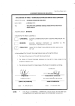
DECLARATION OF THESIS / UNDERGRADUATE PROJECT PAPER AND COPYRIGHT
Author’s full name :
MUHAMMAD SAZALI BIN HISHAM
Date of birth
:
23rd SEPTEMBER 1988
Title
: RFID-BASED ATTENDANCE SYSTEM WITH REMOTE MONITORING
Academic Session : 2010/2011
I declare that this thesis is classified as :
CONFIDENTIAL
(Contains confidential information under the Official Secret
Act 1972)*
RESTRICTED
(Contains restricted information as specified by the
organisation where research was done)*
OPEN ACCESS
I agree that my thesis to be published as online open access
(full text)
I acknowledged that Universiti Teknologi Malaysia reserves the right as follows :
1. The thesis is the property of Universiti Teknologi Malaysia.
2. The Library of Universiti Teknologi Malaysia has the right to make copies for the purpose
of research only.
3. The Library has the right to make copies of the thesis for academic exchange.
Certified by :
SIGNATURE
880923-56-5121
(NEW IC NO. /PASSPORT NO.)
Date : 19 MAY 2011
NOTES :
*
SIGNATURE OF SUPERVISOR
ZURAIMI BIN YAHYA
NAME OF SUPERVISOR
Date : 19 MAY 2011
If the thesis is CONFIDENTIAL or RESTRICTED, please attach with the letter from
the organisation with period and reasons for confidentiality or restriction.
“ I declare that I have read this work and in my opinion this work is
adequate in terms of scope and quality for the purpose of awarding a degree of
Bachelor of Engineering (Electrical - Computer).”
Signature
: …………………………
Name of Supervisor : En. Zuraimi Bin Yahya
Date
: 19 MAY 2011
RFID BASED ATTENDANCE SYSTEM WITH REMOTE MONITORING
MUHAMMAD SAZALI BIN HISHAM
A thesis submitted in fulfillment of the
requirements for the award of the degree of
Bachelor of Engineering (Electrical - Computer)
Faculty of Electrical Engineering
Universiti Teknologi Malaysia
May 2011
ii
“I declare that this work as the product of my own effort with the exception
of excerpt cited from other works which the sources were duly noted”
Signature
: ……………………………….
Name of Candidate : Muhammad Sazali Bin Hisham
Date
: 19 MAY 2011
iii
Dedicated to my beloved father, mother, sisters and brother, and not forgetting my
friends.
iv
ACKNOWLEDGMENT
Alhamdulillah, praise to Allah for the guidance and strength given to me to
complete this project. Peace and blessing upon Prophet Muhammad S.A.W who has
bring the light to all mankind.
I would like to express the deepest gratitude to my supervisor Encik Zuraimi bin
Yahya who has gave me some brilliant idea in order to complete the project. His
willingness to spend time to guide me is much appreciated.
I would like to thank my parents who have support me mentally and financially. I
also would like to thank my siblings who willing to share their experiences which really
motivate me to get my project done.
Besides that, I would like to thank to all my friends especially close friends in
UTM for helping me mentally in completing this project. All the difficulties are shared
together and it makes me keep going.
Lastly, thanks to all lecturers and technicians who have taught me throughout my
four years study in UTM. The knowledge gained from them is one of the factor that
contributing to this project completion.
Thank you very much. May Allah bless all of you.
v
ABSTRACT
Radio Frequency Identification (RFID) technology has been widely used by
various industries as a part of an automation system. In this study, an RFID based
system has been built in order to produce more efficient time-attendance management
system. This system consists of 3 main parts which is an RFID reader, a host computer
and a remote computer. The RFID reader, which is a low-frequency reader (125 kHz),
connected to the host computer either to via serial port or USB port. The host computer
prototype was built using Intel Desktop Board D401PT which has an integrated Intel
Atom processor and run Windows operating system. There were two graphical user
interfaces (GUI) developed in which are the Time-Attendance System and the Remote
Monitoring Client. These GUIs were developed via Microsoft Visual Studio using
C#.Net
language.
The
Time-Attendance
Management
System
provides
the
functionalities of the overall system such as displaying live ID tags transactions,
registering ID, deleting ID, recording attendance and the other minor functions. This
interface was installed in the host computer. In contrast, the Monitoring Client was
installed in the remote computer where remote monitoring can be executed using
Remote Desktop Protocol technology. The host computer and the remote computer were
connected using Local Area Network (LAN).This management system provides
convenient and efficient attendance recording plus saving user’s energy. It is suitable for
indoor use as an office solution or the class attendance system for academic institutes.
vi
ABSTRAK
Teknologi RFID telah digunakan secara meluas dalam pelbagai industri sebagai
sebahagian daripada sistem automatik yang digunakan. Dalam projek ini, sebuah sistem
kehadiran menggunakan teknologi RFID telah dibina. Sistem ini terbahagi kepada tiga
komponen utama iaitu pengimbas RFID, komputer hos dan komputer remote.
Pengimbas RFID yang digunakan ialah pengimbas pada frekuensi rendah (125 kHz) dan
disambung ke komputer hos melalui port sesiri atau port USB. Prototaip bagi komputer
hos dibina menggunakan Intel Desktop Board D410PT yang mengintegrasikan
pemproses Intel Atom. Komputer ini beroperasi menggunakan sistem pengoperasian
Window. Terdapat dua GUI yang dibina iaitu Time Attendance dan juga Remote
Monitoring Client. GUI ini dibina di dalam Microsoft Visual Studio dengan
menggunakan bahasa aturcara C#.Net. Fungsi-fungsi utama keseluruhan sistem ini
terdapat di dalam Time Attendance seperti memaparkan transaksi tag ID secara
langsung, mendaftar ID, memadam ID, merekod kehadiran dan diikuti fungsi-fungsi
sampingan yang lain. Perisian Time Attendance ini disimpan di dalam komputer hos.
Pengawasian jarak jauh boleh dilakukan menggunakan perisian Remote Monitoring
Client yang disimpan di dalam komputer remote. Remote Monitoring Client ini dibina
berdasarkan teknologi Remote Desktop Protocol. Komputer hos dan komputer remote
berhubung melalui rangkaian dalaman (LAN). Sistem ini memudahkan pengrekodan
kehadiran dan ia dilakukan secara efisyen. Selain itu ia menjimatkan tenaga pengguna.
Sistem ini sesuai untuk kegunaan dalaman seperti di dalam pejabat ataupun di dalam
kelas di institusi pengajian.
vii
TABLE OF CONTENTS
CHAPTER
TITLE
DEDICATION
ACKNOWLEDGEMENT
ABSTRACT
ABSTRAK
TABLE OF CONTENTS
LIST OF TABLE
LIST OF FIGURES
LIST OF ABBREVIATIONS
LIST OF APPENDICES
1
2
PAGE
iii
vi
v
vi
vii
ix
x
xii
xiv
INTRODUCTION
1.1 Background of Project
1.2 Problem Statement
1.3 Objectives of Project
1.4 Scope of Project
1.5 Work Contribution
1
2
3
3
5
LITERATURE REVIEW
2.1 Radio Frequency Identification (RFID)
2.1.1 RFID tags
2.1.1.1 Passive RFID tag
2.1.1.2 Active RFID tag
2.1.2 RFID Frequency Band
2.1.3 IDR-232 RFID Reader
2.2 Serial Data Transmission
2.2.1 RS-232 Interface
2.2.2 UART
2.3 Universal Serial Bus
2.3.1 USB to Serial Converter
2.4 Microsoft Visual Studio
2.5 Microsoft .NET Framework
2.6 C# Programming Language
2.7 Microsoft Office Access
2.8 Remote Desktop Protocol
2.9 Internet Information Service (IIS)
8
9
9
10
10
12
13
14
16
17
18
19
20
21
22
23
24
viii
3
4
5
METHODOLOGY
3.1 Hardware Implementation
3.1.1 RFID Reader
3.1.2 RFID Tags
3.1.3 Host Computer
3.1.4 USB to Serial Converter
3.2 Software Implementation
3.2.1 Microsoft Access Database
3.2.2 GUI Design
3.2.2.1 Time Attendance GUI
3.2.2.2 Remote Monitoring Client GUI
3.2.3 Coding Technique
3.2.3.1 Database Interfacing
3.2.3.2 Database Queries
3.2.3.3 ASCII to Hexadecimal Converter
3.2.3.4
Comparing Two Time Format
Number
3.2.3.5 Serial Port Interfacing
RESULT AND DISCUSSION
4.1 RFID Reader Output Test
4.2 System Login
4.3 Main Menu
4.4 Account Setting
4.4.1 Adding or Deleting User
4.4.2 User List
4.4.3 Change Password
4.5 Time Attendance Main Interface
4.5.1 Registration
4.5.2 Deletion
4.5.3 Database Interface
4.5.4 Time Limit Setting
4.5.5 Records
4.6 Attendance Marking Transaction
4.6.1 New Session Wizard
4.6.2 Starting a Session
4.6.3 Attendance Marking
4.6.4 Ending a Session
4.7 Remote Monitoring Client
CONCLUSION AND RECOMMENDATION
5.1 Conclusion
5.2 Recommendation
5.2.1 Hardware Improvement
5.2.2 Software Improvement
REFERENCES
26
27
28
29
30
31
31
33
33
47
48
49
50
51
51
52
55
56
57
58
60
61
62
63
64
66
67
69
70
71
71
72
73
75
76
78
78
79
79
80
ix
LIST OF TABLES
TABLE NO.
3.1
TITLE
RFID Frequency Chart
PAGE
11
x
LIST OF FIGURES
FIGURES NO.
TITLE
PAGE
1.1
1.2
1.3
System block diagram
Gantt chart of the project schedule for Semester 1
Gantt chart of the project schedule for Semester 2
4
6
7
2.1
2.2
2.3
2.4
2.5
2.6
2.7
IDR-232 RFID Reader
Serial Data Transmission
Different Direction of Serial Data Flow
Direct-to-Computer RS-232 Interface
Pin Description of DB-9 Female Connector
UART Architecture
System Flow Diagram of RDP
12
13
14
15
15
16
24
3.1
3.2
3.3
3.4
3.5
3.6
3.7
3.8
3.9
3.10
3.11
3.12
3.13
3.14
3.15
3.16
3.17
3.18
3.19
3.20
3.21
3.22
IDR-232 RFID Reader
RFID Tags
Host Computer Prototype
USB to Serial Converter
“LoginDB” Database
“TADB” Database
Flowchart of Login Transaction
System Login Design
Main Menu Interface Design
Login Record GUI Design
Account Setting GUI Design
Add/Delete GUI Design
Time Attendance Main GUI Design
New Registration Interface Design
Insert/Update Tag ID Design
Flowchart of New Registration Operation
Deletion Interface Design
Flowchart of Delete ID Event
Database GUI Design
Time Limit GUI Design
Login Form Design
Monitor Form Design
27
28
29
30
32
32
34
35
36
37
38
39
40
41
41
42
43
44
45
46
47
48
xi
3.23
3.24
3.25
3.26
3.27
3.28
3.29
3.30
Source Code Used to Connect to Database
SQL Queries with try-catch statement
Displaying Data in Database Interface using Data Row
ASCII to Hexadecimal Converter
SerialPort.DataReceived declaration
Cross-Thread Operation using Delegate Method
Basic DataReceived Event Handler
Flowchart of Scanning Tag ID Transaction
49
50
50
51
52
53
53
54
4.1
4.2
4.3
4.4
4.5
4.6
4.7
4.8
4.9
4.10
4.11
4.12
4.13
4.14
4.15
4.16
4.17
4.18
4.19
4.20
4.21
4.22
4.23
4.24
4.25
4.26
4.27
RFID reader output test in HyperTerminal application
Login Form
Main Menu
Login Record
Account Setting for Administration
Account Setting for Guest User
Add/Delete User Interface
Prohibition from deleting administrator account
User List Interface
Change Password Interface
Time Attendance Interface
Registration form for new registration
Update tag ID
Deletion Interface
Deleting a Profile ID using Guest User Account
Database Interface
Database in List View
Interface of Time Limit setting
Choosing a record file through the interface
Opening the record file using PDF file reader
New Session Wizard form
Start Session Event
Transaction displayed on the terminal
Today’s List showing the attendance marking
Attendance Summary
Remote Client Interface
Successful connection to the host computer
55
56
57
58
59
59
60
61
62
63
63
64
65
66
67
68
68
69
70
71
72
73
74
74
75
76
77
xii
LIST OF ABBREVIATIONS
RF
-
Radio Frequency
ID
-
Identification
RFID
-
Radio Frequency Identification
GUI
-
Graphical User Interface
LAN
-
Local Area Network
USB
-
Universal Serial Bus
EEPROM
-
Electrically Erasable Programmable Read-Only Memory
LF
-
Low Frequency
HF
-
High Frequency
UHF
-
Ultra High Frequency
LED
-
Light Emitting Diode
UART
-
Universal Asynchronous Receiver Transmitter
RS-232
-
Recommended Standard 232
RDP
-
Remote Desktop Protocol
TCP
-
Transmission Control Protocol
IIS
-
Internet Information Service
xiii
RAM
-
Random Access Memory
IP
-
Internet Protocol
LCD
-
Liquid Crystal Display
HTTP
-
Hypertext Transfer Protocol
HTTPS
-
Hypertext Transfer Protocol Secure
FTP
-
File Transfer Protocol
FTPS
-
File Transfer Protocol Secure
SMTP
-
Simple Mail Transfer Protocol
NNTP
-
Network News Transfer Protocol
DAO
-
Data Access Object
VBA
-
Visual Basic for Application
SQL
-
Structured Query Language
xiv
LIST OF APPENDICES
APPENDIX NO.
A
B
TITLE
Source Code
IDR-232N RFID Reader User Manual
PAGE
82
93
1
CHAPTER 1
INTRODUCTION
1.1
Background of Project
In this modern world, there still workplaces or academic institutions that still
using traditional way of taking attendance. For example, attendance sheet method where
attendees need to pass around the sheet to sign it as the proof of attending the session.
There is also “punch card” method which is usually used by factories to mark the
attendance of its workers. Workers need to slot their attendance card into the punch card
machine and put the card into a shell-like slot where the authority can review it.
As technology has advanced, integrating the attendance system with an
automation technology will provides more convenient way in marking the attendance.
The Radio Frequency Identification (RFID) technology is one of an automation
technology that is beneficial in improving current traditional way of attendance marking.
As every tag has its own unique ID, it is easy to differentiate every tag holder.
In addition, a Graphical User Interface (GUI) provides more efficient way to
review the attendance. Thus, the integration of RFID technology and the GUI in an
attendance system will produces an automatic system which give better performance and
efficiency than the traditional method of attendance marking.
2
1.2
Problem Statement
The traditional method of attendance marking has some drawbacks. This method
obviously not efficient as it wastes the user’s energy and quite slow in term of
completion. For example, a class that uses attendance sheet method requires the students
to pass the sheet to each other to sign up the attendance. If there is a large amount of
students, it will take time in order to complete the attendance marking. Besides that,
there is possibility that some students might miss their turn to sign the attendance as they
did not receive the attendance sheet.
It is same goes to the “punch card” system. Workers has to queue up for a long
time as each worker need to punch the card and then put it in the slot provided according
to their names. In summary, both system give drawback in term of performance.
In term of organizing the attendance, there is also a possibility where the
attendance sheet might be lost and this will cause difficulty to review the attendance.
Furthermore, usually there is no copy of the record. As a result, this will produce an
inaccurate overall attendance counting.
3
1.3
Objectives of Project
The main objective in this project is to provide a convenient way of attendance
marking using the RFID technology. In specific, the objectives are:
I.
To build an attendance system that consists of a GUI with the integration of the
RFID technology.
II.
1.4
To enable the attendance system to be monitored remotely.
Scope of Project
This project is mainly focused on GUI development. There are two parts of GUI
to be developed which is the Time Attendance and the Remote Monitoring Client. A
database also been built to store the data.
4
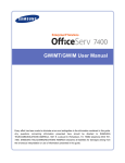
Figure 1.1: System Block Diagram
Figure 1.1 shows the block diagram of the system. The RFID reader is
connected to the host computer via serial port or USB port. The RFID reader is using
RS232 data communication thus a serial to USB converter is required if connection to
the USB port of the host computer is chosen. The Time Attendance GUI is stored in the
host computer with the database while the Remote Client GUI is stored in the remote
computer. The remote computer access the host computer via internetwork within Local
Area Network (LAN).
5
1.5
Work Contribution
RFID-based Attendance System which is able to be monitored remotely is
successfully developed. The main contributions of this project are:
Manage to develop the Time Attendance GUI that capable to track absentees,
count overall absentees and provide lives transaction.
Manage to develop the Remote Monitoring Client GUI that enable user to
monitor the live transaction besides manipulating data.
Manage to integrate the GUI with the database to access data stored.
Successfully tested the system.
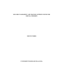
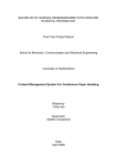
The details of works involved in developing RFID Based Attendance System is shown
in Figure 1.2 and Figure 1.3
6
Week/
Activity
1
2
3
4
5
6
7
8
9
10
11
12
13
Finding
project
title
Discussio
n
on
project
title
Informati
on
findings
Submit
project
proposal
Literature
Review
Learning
C#
Language
Presentati
on
Report
Writing
Figure 1.2: Gantt chart of the project schedule for Semester 1
14
15
16
7
Week/Activity 1
Developing
Remote Client
GUI
Work on
receiving
serial data
from the
interface
Work on
interfacing
database
Developing
Time
Attendance
GUI
Debugging
2
3
4
5
6
7
8
9
10
11
12
13
14
15
Hardware
Installation
and Final
Check
Presentation
Thesis
Writing
Figure 1.3: Gantt chart of the project schedule for Semester
16
17
18
8
CHAPTER 2
LITERATURE REVIEW
2.1
Radio Frequency Identification (RFID)
Radio frequency identification (RFID) is a kind of automatic identification
technology which uses radio waves as the medium to store or retrieve data stored in a
device called RFID tags or transponders. The tags can be applied on animals, product or
a person for the purpose of identification. The distance for the tags to be read by the
reader is varied based on the frequency of the radio wave.
A typical RFID system consists of antenna, transponder and transceiver. The
antenna is used by both transponder and transceiver to transmit the radio waves. The
transceiver reads the radio wave emitted by the transponder and transfers the signal to
the processing device. A transponder is an integrated circuit that contains information to
be transmitted.
As this technology is using radio frequency signal, that’s mean it works wireless.
Generally the reader emits radio wave via an antenna with specified frequency which is
the carrier signal. When the tags detected the signal from the reader, it transmits a
modulating signal which contains the information that has been stored in its integrated
circuit and signal modulation occurs. The antenna of the reader then receives the
modulated signal and feeds it through signal processing circuit of the reader to translate
the information.
9
2.1.1
RFID tags
There are three types of RFID tags; passive, active and semi-passive. The passive
RFID tag requires no internal power source as it gains power from the signal transmitted
by the reader. Thus, it becomes purely passive. The active and semi-passive tag requires
a power source. Commonly the power source is a small battery.
These tags
communicate using backscattering or load modulation technique. Typically load
modulation technique used for short distance reading while the backscattering is used for
far field.
2.1.1.1
Passive RFID tag
The passive RFID tag does not contain a battery. The power is supplied by the
RFID reader. When the tag encounters the radio wave emitted by the reader, the coiled
antenna inside the tag forms a magnetic field thus current induced. The tag draws power
from it and energizes the circuit in the tag. As a result, the tag transmit signal that
contain the information of its memory which received by the signal detector of the
reader to be processed. This type of tag can be read at only short distance (typically a
few feet at most) thus it is more suitable for short distance reading application such as
door access and office solution. Typically this tag has a useful life of twenty years or
more and less expensive. The response of a passive RFID tag is not necessarily just an
ID number; the tag chip can contain non-volatile, possibly writable EEPROM for storing
data.
10
2.1.1.2
Active RFID tag
Active tag is equipped with a battery as the source of power to the tag’s circuitry
and antenna. Some active tag contains replaceable battery for years to use. It is also
possible to use external power supply as the power source of the tag. As active tag
cannot function without a battery, it has limited lifetime. Active tag can be read from a
long distance of hundred feet or more and may have other sensors that can use electricity
for power. It capable to initiate communication and has higher data bandwidth.
2.1.2
RFID Frequency Band
Frequency refers to the size of the radio waves used to communicate between the
RFID system’s components. It can be assumed that higher frequency resulting faster
data transfer rate and longer reading distance. However as frequency increases, the
sensitivity to environmental factor also increases. RFID system currently operates at
Low Frequency (LF), High Frequency (HF) and Ultra High Frequency (UHF). Generally
a lower frequency means a lower read range and slower data read rate, but increased
capabilities for reading near or on metal or liquid surfaces
shown in Table 2.1
[1]
. The frequency chart is
11
Frequency Description Operating Application
Band
Range
125 kHz to Low
< .5 m or
Access
134 kHz
frequency
1.5 ft.
Control
Animal
Tracking
Vehicle
Immobilizer
s
Product
Authenticati
on
POS
Application
13.56 MHz High
<1m or 3
Smart cards
frequency
ft.
Smart
shelve tag
for item
level
tracking
Library
books
Airline
baggage
Maintenance
data logging
860 MHz
Ultra High
3 m or 9ft. Pallet
to 930
Frequency
tracking
MHz
(UHF)
Carton
tracking
Electronic
toll
collection
Parking lot
access
2.4 GHz
Microwave 1m or 3ft. Airline
baggage
Electronic
toll
collection
Benefit
Drawback
Works
well
around
water and
metal
product.
Short read
range and
slower
read rate.
Low cost
of tags
Higher
read rate
than LF
EPC
standard
built
around
this
frequency
Does not
work well
with high
water or
metal
content.
Most
Fastest
expensive read rates
Table 2.1: RFID Frequency Chart
12
2.1.3
IDR-232 RFID Reader
Figure 2.1: IDR-232 RFID Reader
Description and specifications:
9600 baud RS232 serial interface (output only) to PC.
Fully operation with 5VDC power supply from USB port.
Red and green color LED for visual indication of activity.
Standard RS232 serial cable (female) ready to plug to desktop PC.
USB as power source from desktop PC.
2cm reading range.
0.1s response time.
14 bytes of data received include start of text, RFID ID, carriage return, new
line, and end of text.
Frequency band used : 125 kHz (Low Frequency)
13
2.2
Serial Data Transmission
Serial data transmission is widely for transmission of digital data. Serial
transmission means data is sent one bit after another sequentially (bit-serial) in one
transmission line. It is also possible to have high data rate through this transmission as
the increased time consumption required using this type of transmission is acceptable for
most cases. Figure 2.2 shows the simple 2-wire for bit-serial data transmission.
Figure 2.2: Serial Data Transmission
There are three types of data flow direction which are simplex, half duplex and
full duplex. For simplex, data direction is only in one flow. In the other words, it can
only transmit or receives data. Half duplex direction means the stations have to take
turns to transmit data. It shares a line to transmit their data so the data transmission for
both stations cannot be at the same time. The other type is full duplex which data from
both stations can exchanges data simultaneously. The illustration of the direction of
serial data flow can be seen in Figure 2.3
14
Figure 2.3: Different Direction of Serial Data Flow
2.2.1
RS-232 Interface
RS-232 Interface (Recommended Standard 232) is a standard defines by
Electronic Industries Association (EIA) for serial data transmission. This standard uses
asynchronous data transmission where a word consists of a start bit, seven or eight data
bits, optional one parity bit and one or two stop bits. The transmission can be executed
minimally using three wires: send data, receive data and signal ground. The minimum
recognized voltage of this standard is 3V. It specifies that logic “1” has been sent when
the voltage is -3V to -15V while logic “0” when the voltage is 3V to 15V. Typically the
speed of the transmission measured in baud rate which is 150 times an integer power of
2, ranging from 0 to 7 (150, 300, 600 ,...., 19,200 ). The standard has not defines the
maximum cable length but the maximum capacitance that a compliant drive circuit must
tolerate. A widely-used rule-of-thumb indicates that cables more than 50 feet (15 meters)
long will have too much capacitance, unless special cables are used. The most common
connector used for modern computer is DB-9 type.
15
Figure 2.4: Direct-to-Computer RS-232 Interface
Figure 2.5: Pin Description of DB-9 Female Connector
16
2.2.2
UART
Universal Asynchronous Receiver Transmitter (UART) is a component used to
convert between parallel data transmission and serial data transmission. Thus UART is
essential especially for asynchronous serial data transmission. As microprocessor uses
parallel data transmission, it has to be converted into serial data stream before it fed into
serial data line. UART convert byte into serial bit data or a group of serial bit data into
byte.
When two or more devices communicate with each other using asynchronous
communication, and the devices operate at independent clock, it requires
synchronization bits to maintain the integrity of the signal. This is because there is no
guarantee that the clocks of the communicating devices have exactly same frequency
and phase for an extended period. Because of that, UART is required to provide the
synchronization bits. The simplified UART architecture is shown in Figure 2.6
Figure 2.6: UART Architecture
17
CPU Bus Controller provides the parallel data I/O interface to the local processor
bus. It generates the control signal to enable the CPU to have the access onto the data,
status and control register in the UART circuit .The Baud Rate Generator generates a
periodic pulse which determines the baud rate of the transmission. This transmit and
receive bit timing device is programmable so the baud rate can be set according the
programming value. The transmitter is responsible for serial transmitting of the data
which is written by the CPU onto the TxD Hold Register (or FIFO) at the CPU Bus
Controller block while the receiver block detects the start bit of the incoming serial data
and sample the data, bit by bit according to the baud clock of the baud rate generator. It
complete the receive process of a symbol (6, 7 or 8 bit of data) after detecting the stop
bits. It also executes parity check to ensure the correctness of the frame of data.
2.3
Universal Serial Bus
Universal Serial Bus (USB) is a bus system which allows more than one
peripheral to be connected to a host computer via one USB port. Hubs can be used in the
USB chain to extend the cable length and allow for even more devices to connect to the
same USB port. The standard not only describes the physical properties of the interface,
but also the protocols to be used. Because of the complex USB protocol requirements,
communication with USB ports on a computer is always performed via a device driver.
When the host powers up, it queries all of the devices connected to the bus and assigns
each one an address. This process is called enumeration. Devices are also enumerated
when they connect to the bus. The host also finds out from each device what type of data
transfer it wishes to perform:
Interrupt - A device like a mouse or a keyboard, which will be sending very little
data, would choose the interrupt mode.
18
Bulk - A device like a printer, which receives data in one big packet, uses the
bulk transfer mode. A block of data is sent to the printer (in 64-byte chunks) and
verified to make sure it's correct.
Isochronous - A streaming device (such as speakers) uses the isochronous mode.
Data streams between the device and the host in real-time, and there is no error
correction.
The host can also send commands or query parameters with control packets. As
devices are enumerated, the host is keeping track of the total bandwidth that all of the
isochronous and interrupt devices are requesting. They can consume up to 90 percent of
the 480 Mbps of bandwidth that's available (USB 3.0 increases that speed to 4.8 gigabits
per second). After 90 percent is used up, the host denies access to any other isochronous
or interrupt devices. Control packets and packets for bulk transfers use any bandwidth
left over (at least 10 percent).
The Universal Serial Bus divides the available bandwidth into frames, and the
host controls the frames. Frames contain 1,500 bytes, and a new frame starts every
millisecond. During a frame, isochronous and interrupt devices get a slot so they're
guaranteed the bandwidth they need. Bulk and control transfers use whatever space is
left. The technical links at the end of the article contain lots of detail if you'd like to learn
more.
2.3.1
USB to Serial Converter
Defining RS232 communications and ports are often almost directly accessed in
the application program. Settings like baud rate, data bits, and hardware software flow
control can often be changed within the application. In contrast, the USB interface does
not give this flexibility. However, when an RS232 port is used via an USB to RS232
19
converter, this flexibility should be present in some way. Therefore to use an RS232 port
via an USB port, a second device driver is necessary which emulates a RS232 UART,
but communicates via USB.
RS232 ports which are physically mounted in a computer are often powered by
three power sources: +5 Volts for the UART logic, and -12 Volts and +12 Volts for the
output drivers. USB however only provides a +5 Volt power source. Some USB to
RS232 converters use integrated DC/DC converters to create the appropriate voltage
levels for the RS232 signals, but in very cheap implementations, the +5 Volt voltages is
directly used to drive the output.
2.4
Microsoft Visual Studio
Microsoft Visual Studio is an Integrated Development Environment from
Microsoft. It can be uses to develop console and graphical user interface application
along with Windows Forms applications, web sites, web applications, and web services
in both native code together with managed code for all platforms supported by Microsoft
Windows, Windows Mobile, Windows CE, .NET Framework, .NET Compact
Framework and Microsoft Silverlight. Visual Studio includes a code editor supporting
IntelliSense as well as code refactoring. The integrated debugger works both as a sourcelevel debugger and a machine-level debugger. Other built-in tools include a forms
designer for building GUI applications, web designer, class designer, and database
schema designer. Visual Studio supports different programming languages by means of
language services, which allow the code editor and debugger to support (to varying
degrees) nearly any programming language, provided a language-specific service exists.
Built-in languages include C/C++ (via Visual C++), VB.NET (via Visual Basic .NET),
C# (via Visual C#), and F# (as of Visual Studio 2010). Support for other languages such
as M, Python, and Ruby among others is available via language services installed
20
separately. It also supports XML/XSLT, HTML/XHTML, JavaScript and CSS.
Individual language-specific versions of Visual Studio also exist which provide more
limited language services to the user: Microsoft Visual Basic, Visual J#, Visual C#, and
Visual C++.
2.5 Microsoft .NET Framework
The Microsoft .NET Framework is a software framework that can be installed on
computers running Microsoft Windows operating systems. It includes a large library of
coded solutions to common programming problems and a common language
infrastructure that manages the execution of programs written specifically for the
framework. The .NET Framework supports multiple programming languages in a
manner that allows language interoperability, whereby each language can utilize code
written in other languages; in particular, the .NET library is available to all the
programming languages that .NET encompasses.
The framework's Base Class Library provides a large range of features including
user interface, data access, database connectivity, cryptography, web application
development, numeric algorithms, and network communications. The class library is
used by programmers, who combine it with their own code to produce applications.
Programs written for the .NET Framework execute in a software environment
that manages the program's runtime requirements. Also part of the .NET Framework,
this runtime environment is known as the Common Language Runtime (CLR). The CLR
provides the appearance of an application virtual machine so that programmers need not
consider the capabilities of the specific CPU that will execute the program. The CLR
also provides other important services such as security, memory management, and
exception handling. The class library and the CLR together constitute the .NET
Framework.
21
2.6
C# Programming Language
C# is a multi-paradigm programming language encompassing imperative,
declarative, functional, generic, object-oriented (class-based), and component-oriented
programming disciplines. It was developed by Microsoft within the .NET initiative and
later approved as a standard by ECMA (ECMA-334) and ISO (ISO/IEC 23270). C# is
one of the programming languages designed for the Common Language Infrastructure.
The goals of this programming language design are:
C# language is intended to be a simple, modern, general-purpose, object-oriented
programming language.
The language, and implementations thereof, should provide support for software
engineering principles such as strong type checking, array bounds checking,
detection of attempts to use uninitialized variables, and automatic garbage collection.
Software robustness, durability, and programmer productivity are important.
The language is intended for use in developing software components suitable for
deployment in distributed environments.
Source code portability is very important, as is programmer portability, especially
for those programmers already familiar with C and C++.
Support for internationalization is very important.
C# is intended to be suitable for writing applications for both hosted and embedded
systems, ranging from the very large that use sophisticated operating systems, down
to the very small having dedicated functions.
Although C# applications are intended to be economical with regard to memory and
processing power requirements, the language was not intended to compete directly
on performance and size with C or assembly language.
22
2.7
Microsoft Office Access
Microsoft Office Access, previously known as Microsoft Access, is a pseudorelational database management system from Microsoft that combines the relational
Microsoft Jet Database Engine with a graphical user interface and software-development
tools. It is a member of the Microsoft Office suite of applications, included in the
Professional and higher editions or sold separately. In mid-May 2010, the current
version Microsoft Office Access 2010 was released by Microsoft in Office 2010;
Microsoft Access 2007 was the prior version. Access stores data in its own format based
on the Access Jet Database Engine. It can also import or link directly to data stored in
other applications and databases.
Software developers and data architects can use Microsoft Access to develop
application software, and "power users" can use it to build simple applications. Like
other Office applications, Access is supported by Visual Basic for Applications, an
object-oriented programming language that can reference a variety of objects including
DAO (Data Access Objects), ActiveX Data Objects, and many other ActiveX
components. Visual objects used in forms and reports expose their methods and
properties in the VBA programming environment, and VBA code modules may declare
and call Windows operating-system functions.
23
2.8
Remote Desktop Protocol
Remote Desktop Protocol (RDP) is a protocol developed by Microsoft where it
enables a computer to have the graphical interface of another user. The clients exist for
most versions of Microsoft Windows (including Windows Mobile), Linux, Unix, Mac
OS X and other modern operating systems. By default the server listens on Transmission
Control Protocol (TCP) port 3389. The TCP provide the service of exchanging data
between to network hosts.
In order to enable the protocol, the host computer makes a connection to
Windows Terminal Server and the client computer get the access of the host from the
terminal. Thus, only keyboard, mouse, and display information are transmitted over the
network as all applications are hosted on the Terminal Server. As a result it works well
even under low-bandwidth conditions[2]. The system flow diagram of RDP is shown in
Figure 2.7
24
Figure 2.7: System Flow Diagram of RDP
2.9
Internet Information Service (IIS)
Internet Information Services (IIS) is a web server application and set of feature
extension modules created by Microsoft for use with Microsoft Windows. It is the
second most used web server behind Apache HTTP Server. The protocols supported in
latest IIS, IIS 7.5 include: FTP, FTPS, SMTP, NNTP, and HTTP/HTTPS. There are
some modules featured in IIS which are:
25
HTTP modules – Used to perform tasks specific to HTTP in the request-processing
pipeline, such as responding to information and inquiries sent in client headers,
returning HTTP errors, and redirecting requests.
Security modules – Used to perform tasks related to security in the requestprocessing pipeline, such as specifying authentication schemes, performing URL
authorization, and filtering requests.
Content modules – Used to perform tasks related to content in the request-processing
pipeline, such as processing requests for static files, returning a default page when a
client does not specify a resource in a request, and listing the contents of a directory.
Compression modules – Used to perform tasks related to compression in the requestprocessing pipeline, such as compressing responses, applying Gzip compression
transfer coding to responses, and performing pre-compression of static content.
Caching modules – Used to perform tasks related to caching in the requestprocessing pipeline, such as storing processed information in memory on the server
and using cached content in subsequent requests for the same resource.
Diagnostics modules – Used to perform tasks related to logging and diagnostics in
the request-processing pipeline, such as passing information and processing status to
HTTP.sys for logging, reporting events, and tracking requests currently executing in
worker processes.
26
CHAPTER 3
METHODOLOGY
In order to implement the RFID-Based Attendance System with monitoring
capability, an RFID reader, a host computer and a remote computer are required. There
are two software to be developed which are the Time Attendance that to be stored in the
host computer and the Remote Monitoring Client that to be stored in the remote
computer.
3.1
Hardware Implementation
The hardware required to complete the system are the RFID reader with its tag, a
host computer, a remote computer which is any available computer and a USB to serial
converter. However, there is no hardware to be developed as all the hardware required
are plug and play type and this project is more focused on developing the software.
27
3.1.1
RFID Reader
The RFID reader used in this project is called IDN-232 RFID Reader. This RFID
reader uses low frequency band, which is 125 kHz. Practically, the reading distance
between the tag and the reader is about 2 cm. The output of this reader is transmitted
serially. It also transmitted data at 9600 baud rates.
Figure 3.1: IDR-232 RFID Reader
The reason that this reader has been chosen is because it has a DB9 female
header, which can be used to connect to the serial port of personal computer. The IDN232 RFID Reader also provides a simple way to check its functionality. It can display
the unique ID of the tag through the HyperTerminal application in Window operating
system.
28
3.1.2
RFID Tags
Figure 3.2: RFID Tags
Figure 3.2 shows the RFID tags used in this project. These RFID tags are
passive tags thus it has no internal power supply. These tags activated by radio
frequency transmitted by the reader. The reading distance is about 3 cm. When the RFID
reader receives the data from the tag, the data then will be compared with the data in the
database to identify the holder of the tag.
29
3.1.3
Host Computer
In order to test and demonstrate the full system functionality, a prototype host
computer has been built. Intel D410PT Desktop Board has been selected as the
motherboard because of its mini-ITX size and it also has on board Intel Atom 1GHz
speed processor in a reasonable price. A 1GB DDR2 RAM is used to run this computer
and an 80GB SATA hard disk as the storage. A Cooler Master CPU Fan also been used
to enhance the cooling process. To power up the computer, a 300W ATX power supply
is used.
Figure 3.3: Host Computer Prototype
30
3.1.4
USB to Serial Converter
A USB to Serial Computer is used in order to provide versatility to this system.
With the help of this converter, the RFID reader can be connected whether to the serial
port or to the USB port of the host computer. The converter has its own driver provided
which has to be installed in the host computer. The host computer will treats the data
similarly to the serial port connection but using different COM port.
Figure 3.4: USB to Serial Converter
31
3.2
Software Implementation
There are two interfaces that to be developed which are the Time Attendance and
the Remote Monitoring Client. These interfaces are developed using C# programming
language via Microsoft Visual Studio 2008. In the other hand, the databases are built
using Microsoft Access 2007.
3.2.1
Microsoft Access Database
There are two databases are built using Microsoft Access 2007. The databases
named “LoginDB” and “TADB”. The “LoginDB” database stores login information for
Time Attendance interface. This information also used in admin identification for
manipulating attendance information. In the other hand, the “TADB” database stores all
attendance- related data. The password data is saved in password character as it is a
private data. Besides that, there are two tables inside the “TADB” database which act as
temporary data storage which are “SessionDB” and “TempDB”. Both tables are
essential to the program flows. In order to increase the security, both databases are
password protected.
32
Figure 3.5: “LoginDB” Database
Figure 3.6: “TADB” Database
33
3.2.2
GUI Design
As mentioned before, the GUI of the Time Attendance and the Remote
Monitoring Client is developed using Microsoft Visual Studio 2008. However, it is
difficult to design an attractive GUI using the basic controls provided by the Microsoft
Visual Studio. Thus, third party add-on software which is Developer Express 2010 has
been used to enhance the appearance of the GUI. This software is integrated into
Microsoft Visual Studio 2010.
3.2.2.1
Time Attendance GUI
The Time Attendance interface is divided into two parts which are login part and
the main interface part. The purpose of the login part is to make the system more secure
as user has to login before having the access of the main interface. The folder of the
design project is named “Final GUI” and the project file name is “FGUI”. The output of
the compilation is in “Debug” folder within the project folder. The flowchart of login
transaction is shown in Figure 3.7
34
Figure 3.7: Flowchart of login transaction
35
Figure 3.8: System Login Design
Figure 3.8 shows the design of the system login interface. “Login” button
handles the login event by searching the username and password inserted in the
corresponding textboxes in the database for matched ID. The “Cancel” button control is
responsible to close the application. The design names of the textboxes are “tb_uname”
and “tb_pass”.
36
Figure 3.9: Main Menu Interface Design
Figure 3.9 shows the GUI design of Main Menu. This interface act as an
intermediary interface because the three buttons, “Account Setting”, ’Time Attendance”,
and “Login Record” only responsible to call their corresponding forms. The button
“Logout” used to return to the System Login form.
37
Figure 3.10: Login Record GUI Design
Figure 3.10 shows the GUI design of Login Record. In order to display the
record, a data grid view control has been used. Three button controls also included
which are “Back”, “Clear” and “Refresh”. “Back” button used to return to the Main
Menu. “Clear” button handles on clearing the record permanently while “Refresh”
button used to update the grid view. The design name of this interface is “Form 7”.
38
Figure 3.11: Account Setting GUI Design
Figure 3.11 shows the GUI design of Account Setting. Three button controls,
“Add/Delete User”, ”User List” and “Change Password” included in this interface as
the main control to call their respective form. A textbox with design name “tb_logas”
used to display the name of user who logged in. “Back” button control used to return to
previous form.
39
Figure 3.12: Add/Delete User GUI Design
Figure 3.12 shows the interface design of Add/Delete User, the form that will be
called when button “Add/Delete User” in the Account Setting form pressed. The design
name of this form is “Form11”.The design name for the textboxes are
“tb_fnama”(fullname),“tb_unama”(username), tb_pass”(password), “tb_npass”(confirm
password) and “tb_delfnama”(delete fullname).
40
Figure 3.13: Time Attendance Main GUI Design
Figure 3.13 shows the Time Attendance Main Interface Design. Tab control has
been used to reduce forms required to implement the main features available. Features
included in this interface are live transaction terminal, ID registration, ID deletion, view
database, searching, set time limit, and view session record. Button controls in the Menu
used to open the tab respectively according to their names, except “Exit” button which
used to close this form and return to Main Menu form and also “Records” button which
use open file dialog control to open the record files. Default tab opened when this form
has loaded is the terminal tab as shown in Figure 3.13
41
Figure 3.14: New Registration Interface Design
Figure 3.15: Insert/Update Tag ID Interface Design
42
The design of Registration interface is consist of two tabbed interfaces which are
New Registration and Insert/Update Tag ID as shown in Figure 3.14 and Figure 3.15.
New Registration interface used to execute full registration. In contrast, Insert/Update
Tag ID interface is used if the details inserted manually to database via Microsoft
Access except for the tag ID. This is because the tag ID stored in the database in
hexadecimal format instead of its default format which is ASCII format. Thus the
interface provides the converter from ASCII format to hexadecimal format before the
tag ID is stored into the database. In this design, Admin Identification feature also has
been built in order to enable only Administrator type of user can makes the registration
operation. The New Registration implementation should follow the flowchart in Figure
3.16
Figure 3.16: Flowchart of New Registration operation
43
Figure 3.17: Deletion Interface Design
Figure 3.17 shows the Deletion interface design. An ID can be deleted by
inserting its full name or its ID number. This operation will also require Admin
Identification as same as Registration operation. The flowchart of Deletion operation is
shown in Figure 3.18
44
Figure 3.18: Flowchart of Delete ID Event
45
Figure 3.19: Database GUI Design
Figure 3.19 shows the database GUI design. This interface used to display
the details of every registered profile ID. The number of days absent per meeting also
can be viewed via this interface. Besides that, any profile ID can be searched via this
interface by inserting its full name or ID number in the search’s textbox. A less detailed
database view also provided by clicking the button “View In List” which will call
another form that uses data grid view control to display the database.
46
Figure 3.20: Time Limit GUI Design
Figure 3.20 shows the time limit GUI design. This interface used to set
the time limit after a session has been created. Radio button control has been used as the
options of the time range. The range of time available is between 5 to 30 minutes after
the port has been opened. When the time limit has end, the attendees that scan their tags
should be marked as late. An identification to enable this feature also provided.
However, this feature can be enabled by using both admin and guest user account as the
username and password in the admin identification.
47
3.2.2.2
Remote Monitoring Client GUI
Two forms have been used to develop the Remote Monitoring Client GUI which
is login form and the monitor form. The login information is inserted in the login form
while the monitor form will provides the view and control of the host computer. The
view and the control of the host computer are gained by using the Microsoft Terminal
Service Control Library. The GUI design of these forms are shown in Figure 3.21 and
Figure 3.22
Figure 3.21: Login Form Design
48
Figure 3.22: Monitor Form Design
3.2.3
Coding Technique
The code behind the interface is mostly class-based code as in C#.NET, every
control has its own class library that provide the desired output when the controls have
been interrupted. Functions also have been used to make the program well organized.
49
3.2.3.1
Database Interfacing
As the database is built using Microsoft Access, the connection to the database
can be established using OleDb connection. DataAdapter also been used to implement
dataset method to get the data from the database. The example of source code used is
shown in Figure 3.23
#region Instance Declaration
public OleDbConnection database;
DataSet ds1;
DataSet ds2;
System.Data.OleDb.OleDbDataAdapter
System.Data.OleDb.OleDbDataAdapter
System.Data.OleDb.OleDbDataAdapter
System.Data.OleDb.OleDbDataAdapter
System.Data.OleDb.OleDbDataAdapter
System.Data.OleDb.OleDbDataAdapter
#endregion
da;
da1;
da2;
da3;
da4;
da5;
Connecting to the Database
string connectionString = "Provider=Microsoft.Jet.OLEDB.4.0;Data
Source=Databases\\LoginDB.mdb;Jet OLEDB:Database Password= admin";
database = new OleDbConnection(connectionString);
database.Open();
string sql = "SELECT * FROM PassDB";
ds1 = new DataSet();
da = new System.Data.OleDb.OleDbDataAdapter(sql, database);
da.Fill(ds1, "PassDB");
da1 = new System.Data.OleDb.OleDbDataAdapter("SELECT * FROM LogDB",
database);
da1.Fill(ds1, "LogDB");
Figure 3.23: Source Code used to connect to the database
50
3.2.3.2
Database Queries
SQL statements such as INSERT, DELETE and UPDATE are used to retrieve and
manipulate data in the database. Besides that, getting data row from dataset method also
been used to retrieve the data without manipulate it as used to display the data in the
database interface. Furthermore, try-catch statement is implemented to control the
program exception during the queries.
string SQLString;
SQLString = "INSERT INTO
RegDB(Fnama,Icno,Org,Idno,Tagid,Datereg,Tagid2)VALUES('" +
name.Replace("'", "''") + "','" + nric + "','" + org + "','" + idno +
"','" + "1" + ConvertToHex(tagid) + "2" + "','" + DateTime.Now + "','"
+ ConvertToHex(tagid) + "');";
OleDbCommand SQLCommand = new OleDbCommand();
SQLCommand.CommandText = SQLString;
SQLCommand.Connection = database;
int response = -1;
try{
response = SQLCommand.ExecuteNonQuery();}
catch (Exception ex){
MessageBox.Show(ex.Message);}
if (response >= 1){}
Figure 3.24: Example of the usage of SQL queries with try-catch statement
DataRow dr = ds2.Tables["RegDB"].Rows[inc];
tb_fname.Text = dr.ItemArray.GetValue(1).ToString();
tb_nric.Text = dr.ItemArray.GetValue(2).ToString();
tb_dep.Text = dr.ItemArray.GetValue(3).ToString();
tb_idno.Text = dr.ItemArray.GetValue(4).ToString();
string x = dr.ItemArray.GetValue(7).ToString();
tb_tagid.Text = HexString2Ascii(x);
tb_datereg.Text = dr.ItemArray.GetValue(6).ToString();
Figure 3.25: Displaying data in database interface using data row method
51
3.2.3.3
ASCII to Hexadecimal Converter
In order to convert ASCII format number into hexadecimal, String.format
command used. A for each loop also used to convert every single ASCII character. The
function is shown in Figure 3.26
public string ConvertToHex(string asciiString)
{
string hex = "";
foreach (char c in asciiString)
{
int tmp = c;
hex += String.Format("{0:x2}",
(uint)System.Convert.ToUInt32(tmp.ToString()));
}
return hex;
}
Figure 3.26: ASCII to Hexadecimal Converter
3.2.3.4
Comparing Two Time Format Number
Time limit feature needs the comparison of the end time and the time the tag ID
scanned. However it cannot be arithmetically subtracted as time format number is not
the same of integer format number. Thus, DateTime.Compare(Time1 , Time2) command
is used instead. Time1 is the first parameter that will be compared to Time2.
52
3.2.3.5
Serial Port Interfacing
Microsoft Visual Studio provides the serial port class library to make
communication between serial port and the window form. The SerialPort.DataReceived
need to be declared as it is the event handler to read the data from the serial port buffer
as shown in Figure 3.27. This method is interrupt-driven.
private SerialPort comPort = new SerialPort();
comPort.DataReceived += new
SerialDataReceivedEventHandler(comPort_DataReceived);
Figure 3.27: SerialPort.DataReceived declaration
The data from the serial port will be displayed on a rich textbox control.
However, the serial port and the rich textbox control are using different threads. This by
default will produce an exception during runtime as illegal cross-thread operation.
Furthermore as both serial port and the window form control is trying to manipulate the
same data simultaneously, race condition or deadlock may happen and the output will be
incorrect. In order to make a thread-safe call, delegate method used to invoke the crossthread operation as shown in Figure 3.28
53
private RichTextBox _displayWindow;
[STAThread]
private void DisplayData(MessageType type, string msg)
{
_displayWindow.Invoke(new EventHandler(delegate
{
_displayWindow.SelectedText = string.Empty;
_displayWindow.SelectionFont = new
Font(_displayWindow.SelectionFont, FontStyle.Bold);
_displayWindow.SelectionColor = MessageColor[(int)type];
_displayWindow.AppendText(msg);
_displayWindow.ScrollToCaret();
}));
}
Figure 3.28: Cross-Thread operation using delegate method
void comPort_DataReceived(object sender,SerialDataReceivedEventArgs
e)
{
int bytes = comPort.BytesToRead;
byte[] comBuffer = new byte[bytes];
comPort.Read(comBuffer, 0, bytes);
string msg = ByteToHex(comBuffer);
DisplayData(MessageType.Time, DateTime.Now + ": " + "\t");
DisplayData(MessageType.Late, msg + "\n");
}
Figure 3.29: Basic DataReceived Event Handler
Figure 3.29 shows the basic function of DataReceived event handler to
display the data from serial port in the rich textbox control by using DisplayData
function. This function first creates an array of bytes to store the received bytes of data
from the serial port buffer before reading the bytes. Then it will be displayed by using
the DisplayData function. In order to display the name of the Tag ID holder, it will be
compared to the database before being displayed as shown in the flowchart in Figure
3.30
54
Figure 3.30: Flowchart of Scanning Tag ID Transact
55
CHAPTER 4
RESULT AND DISCUSSION
4.1
RFID Reader Output Test
HyperTerminal application has been used to view the output of the RFID reader
after reading the tag as shown in Figure 4.1. The output of the reader is 12 bytes data in
ASCII. The weird characters at the first byte and the last byte are extra byte to indicate
the start and the end of the data. The 10 bytes data between it is the tag unique ID.
Figure 4.1: RFID reader output test in HyperTerminal application
56
4.2
System Login
Figure 4.2: Login Form
Figure 4.2 shows the login form to get the access of the Time Attendance
system. There are two types of user which are administrator and guest user.
Administrator has no data manipulation restriction while guest user has some limitation.
The type of user is identified by comparing the details filled in the form with the details
matched in the database.
57
4.3
Main Menu
Figure 4.3: Main Menu
Figure 4.3 shows the main menu of the system. There are three options which
are account setting, time attendance and login record. Time attendance menu is chosen
to access the time attendance system. Login record displays the record of all login
transaction as shown in Figure 4.4
58
Figure 4.4: Login Record
4.4
Account Setting
In the account setting, there are three menus which are Add or Delete User, User
List and Change Password. However, guest user is restricted from add or delete user and
view user list. Only password change can be done by guest user. Figure 4.5 and Figure
4.6 shows the limitation in account setting menu using different account type.
59
Figure 4.5: Account Setting for Administration
Figure 4.6: Account Setting for Guest User
60
4.4.1
Adding or Deleting User
This menu provides the interface for administrator to add or delete user.
However administrator’s account itself cannot be deleted and there is only one
administrator account in this system. In the other words, only guest user can be added
into the database. Username that is same with one of the username stored in the database
cannot be deleted.
Figure 4.7: Add/Delete User Interface
61
Figure 4.8: Prohibition from deleting administrator account
4.4.2
User List
The User List interface shows the registered user that can access the Time
Attendance system. Only the administrator can view the list. The list shows user’s full
name, username and the type of account. The interface is shown in Figure 4.9
62
Figure 4.9: User List Interface
4.4.3
Change Password
The system also enables the user to change their corresponding password. Both
administrator and guest user have the access of this interface as this is a private setting
for every user. The interface shown in Figure 4.10
63
Figure 4.10: Change Password Interface
4.5
Time Attendance Main Interface
Figure 4.11: Time Attendance Interface
64
Figure 4.11 shows the main interface of the Time Attendance. There are seven
menus which are Terminal, Registration, Deletion, Database, Time Limit, Records, and
Exit. The System Status shows the current status of the system such as whether a session
is running or otherwise, and whether the time limit has been set or otherwise. The Exit
menu will close the form and return to the Main Menu interface while the other menus
will open the corresponding tab. The System Status will show the configuration status of
the port name, session, and time limit.
4.5.1
Registration
Figure 4.12: Registration form for new registration
65
Figure 4.13: Update tag ID
The registration form is divided into two sections which are new registration and
insert or update tag ID. The purpose of new registration form is to register new ID with
full detail required through the interface as shown in Figure 4.12.The details required
are full name, NRIC, ID number, department or class, and tag ID. Only administrator
has the access to register the ID. Besides that, each person cannot have more than one
profile in the same department. The registration form for insert or update tag ID as
shown in Figure 4.13. This option helps when direct registration is made. Direct
registration means the details inserted directly into the database tables. All details can be
inserted directly into the database table except for tag ID because it is stored in
hexadecimal form. Thus it has to be converted into hexadecimal first. Because of that,
this interface provides the ID conversion into hexadecimal before being stored in the
database.
66
4.5.2
Deletion
Figure 4.14: Deletion Interface
Figure 4.14 shows the interface for delete profile ID. A profile ID can be deleted
by inserting its full name or ID number. Only administrator has the access to delete
profile as goes as registration. Figure 4.15 shows the message generated when trying to
delete a profile ID using a guest user account.
67
Figure 4.15: Deleting a Profile ID using Guest User Account
4.5.3
Database Interface
The Time Attendance also provides the interface to view the database as shown
in Figure 4.16. Besides showing the personal details, it also shows the absent count out
of total meetings of every profile ID. The database also can be viewed in list but in less
detailed manner as shown in Figure 4.17. Refresh database function is required to
effectively update the database after any data manipulation on the database has executed.
The profile also can be searched throughout the database by entering the full name or ID
number of the profile.
68
Figure 4.16: Database Interface
Figure 4.17: Database in List View
69
4.5.4
Time Limit Setting
Time Limit is developed to enable the system to set a time limitation of a
session. The range of duration that can be set is between 5 to 30 minutes. The start time
is the time port is opened and the end time is the time when the duration chosen has
ended. Any tag scanned after the duration has ended is still considered as attended, but
the status of the attendance is “LATE”. Both administrator and guest user can set this
time limit feature. The interface of time limit setting is shown in Figure 4.18
Figure 4.18: Interface of Time Limit setting
70
4.5.5
Records
After a session has ended, a record has been saved so it can be reviewed
in future. The record is saved in PDF format file and the file name is based on the name
given to the session during new session wizard. The file can be chose through the
interface but will be opened by PDF file reader application such as Adobe Acrobat
Reader as shown in Figure 4.19 and Figure 4.20
Figure 4.19: Choosing a record file through the interface
71
Figure 4.20: Opening the record file using PDF file reader
4.6
Attendance Marking Transaction
Every time the port is opened is treated as a session. Thus in order to open the
port, a new session has to be created. Once the port is opened, the application can start
reading any tag that has been scanned by the RFID reader.
4.6.1
New Session Wizard
New Session Wizard form will be called when a new session has to be
created. In this wizard, the name of the session, the date of the session and the time of
the session entered. This form also provides choices of department to be involved in that
session. There are two choices of taking attendance which are by department and by
whole company or class. The New Session Wizard form is shown in Figure 4.21
72
Figure 4.21: New Session Wizard form
4.6.2
Starting a Session
Once a new session has been configured in the New Session Wizard, the
Start Session feature will be enabled. When a new session has been created, a temporary
data is stored into temporary database. When the Start Session event is called, the
program will refer to the temporary database to check whether a new session has been
created or vice versa. If the temporary data is in that database, it will proceed to open the
port for tag reading.
73
Figure 4.22: Start Session Event
4.6.3
Attendance Marking
When the tag scanned, the tag ID will be compared for a match in the database.
Once the ID found, the full name and the ID number of the matched profile ID displayed
in the terminal as shown in Figure 4.23. At the same time, the attendance will be
updated from initially “PENDING” to “OK” or “LATE”. The attendance table can be
viewed in Today’s List feature as shown in Figure 4.24.
74
Figure 4.23: Transaction displayed on the terminal
Figure 4.24: Today’s List showing the attendance marking
75
4.6.4 Ending a Session
Ending a session means stopping from taking the attendance. Once the Stop
Session event is called, the form that shows the summary of that session is called. Then
record is written into PDF file and the temporary data in the database is cleared. Lastly,
the port is closed. The session summary form is shown in Figure 4.25.
Figure 4.25: Attendance Summary
76
4.7
Remote Monitoring Client
The inputs required to connect to the host computer are server name, username
and password. Server name is either the IP address of the host computer or the name of
the host computer while the username and password are according to the host computer
account setting. The interface of login form of the Remote Monitoring Client is shown in
Figure 4.26 and a successful connection is as in Figure 4.27
Figure 4.26: Remote Client Interface
77
Figure 4.27: Successful connection to the host computer
78
CHAPTER 5
CONCLUSION AND RECOMMENDATION
5.1
Conclusion
In conclusion, the objective to build an RFID based attendance system that can
be monitored remotely has successfully achieved. In term of performance and efficiency,
this project has provided a convenient method of attendance marking compared to the
traditional method of attendance system. By using databases, the data is more organized.
This system also is a user friendly system and easy to use as data manipulation and
retrieval can be done via the interface. Besides that, all the data required are in general,
making it a universal attendance system. Thus it can be implemented in an academic
institution or in an office.
5.2
Recommendation
Some further improvements can be made on this project in order increases its
reliability and effectiveness. There are two parts of improvements, which are hardware
improvement and software improvement.
79
5.2.1
Hardware Improvement
The current RFID reader used in this project only support very short distance
reading. By replacing this reader with a long range reader, it can increase the
performance of the system as attendees just only need no walk pass by the reader
without actually bringing the tag out. Other than that, a hardware user interface can be
build by the usage of microcontroller, LCD and LED so the attendees can view the
transaction. Furthermore, an IP camera can be integrated into this system to enable the
monitor to view the person who making the transaction. As a result, this can avoid
problem like a person scans in for other person.
5.2.2
Software Improvement
In software part, the database can be made with more detail approach thus every
profile stored has full personal details. A reminder alert also can be developed to
effectively track any ID that has been absent for an unacceptable times in a row. Besides
that, this attendance system can be improved by adding a feature where it can save and
recount the absent record if the absentee has absent under emergency leave or has the
medical certificate as the proof of sickness.
The Remote Client Monitoring also can be improved by expanding the range of
accessibility. Instead of connecting to the host computer through Local Area Network,
the connection can be made between two different networks. Thus, it increases the
mobility of this system.
80
REFERENCES
1. Daniel M. Dobkin and Steven M. Weigand. Environmental Effects on RFID Tag
Antennas. United States. Enigmatics, Sunnyvale, CA, USA and WJ
Communications, San Jose, CA, USA.
2.
Hosted Desktop Virtualization Team(2008). Remote Desktop Protocol Performance.
United States. Microsoft Corporation.
3. IDR-232N RFID Reader Manual : http://www.cytron.com
4. Visual C# programming: http://www.csharpfriends.com
5. Ahmad Zafri Bin Johari (2007). Car Park Control System: Interface RFID to PIC
Using Serial Port. Universiti Teknologi Malaysia: Degree Thesis.
6. Hamizah Binti Mokhtor (2010). Implementation of Parking System Using Radio
Frequency Identification Technology. Universiti Teknologi Malaysia: Degree Thesis.
7. Amirjan Bin Nawabjan (2009). Automated Attendance Management Software.
Universiti Teknologi Malaysia : Degree Thesis.
8. Stevan Preradovic, Nemai C. Karmakar (2006). RFID Reader : A Review. Australia.
Monash University.
9. Information: en.wikipedia.org
10. Serial Port Communication Using C# Tutorial: http://www.codeproject.com
81
11. Nur Raimi binti Mohd Abdul Rashid (2008). Classroom Attendance Using RFID.
Universiti Teknologi Malaysia: Degree Thesis.
12. Understanding Remote Desktop Protocol: http://support.microsoft.com/kb/186607
13. Mc’ Oswel Jamin Sibin(2010). RFID Based Attendance System. Universiti
Teknologi Malaysia: Degree Thesis.
14. C#.Net Programming using COM Interop: http://www.c-sharpcorner.com
15. Intel Desktop Board Specifications: http://www.intel.com
16. Thread Safe Calls to Window Form: http://msdn.microsoft.com
17. Window Form Custom Controls: http://www.devexpress.com
82
APPENDIX A
SOURCE CODE
83
Remote Monitoring Client
Form1 : Login Form
using
using
using
using
using
using
using
using
using
System;
System.Collections.Generic;
System.ComponentModel;
System.Data;
System.Drawing;
System.Text;
System.Windows.Forms;
DevExpress.XtraEditors;
MSTSCLib;
namespace RemoteClient{
public partial class Form1 : DevExpress.XtraEditors.XtraForm
{
public Form1()
{
InitializeComponent();
}
private void simpleButton2_Click(object sender, EventArgs e)
{
txtPassword.ResetText();
txtServer.ResetText();
txtUserName.ResetText();
Application.Exit();
}
private void simpleButton1_Click(object sender, EventArgs e)
{
Form2 f2 = new Form2();
try
{
f2.rdp.Server = txtServer.Text;
f2.rdp.UserName = txtUserName.Text;
IMsTscNonScriptable
secured
=
(IMsTscNonScriptable)f2.rdp.GetOcx();
secured.ClearTextPassword = txtPassword.Text;
f2.rdp.Connect();
f2.Show();
this.Hide();
this.ShowInTaskbar = false;
}
catch (Exception Ex)
{
MessageBox.Show("Error Connecting", "Error connecting to remote
desktop " + txtServer.Text + " Error:
" + Ex.Message,
MessageBoxButtons.OK, MessageBoxIcon.Error);
}
txtPassword.ResetText();
txtServer.ResetText();
txtUserName.ResetText();
}}}
84
Form 2: Monitor Form
using
using
using
using
using
using
using
using
System;
System.Collections.Generic;
System.ComponentModel;
System.Data;
System.Drawing;
System.Text;
System.Windows.Forms;
DevExpress.XtraEditors;
namespace RemoteClient
{
public partial class Form2 : DevExpress.XtraEditors.XtraForm
{
public Form2()
{
InitializeComponent();
}
private void simpleButton1_Click(object sender, EventArgs e)
{
try
{
// Check if connected before disconnecting
if (rdp.Connected.ToString() == "1")
rdp.Disconnect();
}
catch (Exception Ex)
{
Form1 frm1 = new Form1();
MessageBox.Show("Error
Disconnecting",
"Error
disconnecting from remote desktop " + frm1.txtServer.Text + " Error: "
+ Ex.Message, MessageBoxButtons.OK, MessageBoxIcon.Error);
}
Form1 f1 = new Form1();
f1.Show();
this.Close();
}
}
}
85
Time Attendance
Form3 : Time Attendance Main GUI
Register
#region Registration
private void Register()
{
string SQLString;
SQLString
=
"INSERT
INTO
RegDB(Fnama,Icno,Org,Idno,Tagid,Datereg,Tagid2)VALUES('"
+
name.Replace("'", "''") + "','" + nric + "','" + org + "','" + idno +
"','" + "1" + ConvertToHex(tagid) + "2" + "','" + DateTime.Now + "','"
+ ConvertToHex(tagid) + "');";
OleDbCommand SQLCommand = new OleDbCommand();
SQLCommand.CommandText = SQLString;
SQLCommand.Connection = database;
int response = -1;
try
{
response = SQLCommand.ExecuteNonQuery();
}
catch (Exception ex)
{
MessageBox.Show(ex.Message);
}
if (response >= 1)
{
int no = 0;
string SQLString2;
SQLString2
=
"INSERT
INTO
TodayAttDB(Fnama,Icno,Org,Idno,Tagid,Status,xTime,Meeting,Absent)VALUES
('" + name.Replace("'", "''") + "','" + nric + "','" + org + "','" +
idno + "','" + "1" + ConvertToHex(tagid) + "2" + "','" + "n/a" + "','"
+ "n/a" + "','" + no.ToString() + "','"+no.ToString()+"');";
OleDbCommand SQLCommand2 = new OleDbCommand();
SQLCommand2.CommandText = SQLString2;
SQLCommand2.Connection = database;
int response2 = -1;
try
{
response2 = SQLCommand2.ExecuteNonQuery();
}
catch (Exception ex)
{
MessageBox.Show(ex.Message);
}
if (response2 >= 1)
{
DataRow[] row = ds2.Tables["DepDB"].Select("Dep='" + org +
"'");
86
int n = row.Length;
if (n > 0)
{
XtraMessageBox.Show("Registration
Successfully
Completed", "Information");
LoadTADB();
}
else
{
string SQLString3;
SQLString3 = "INSERT INTO DepDB(Dep)VALUES('" + org +
"');";
OleDbCommand SQLCommand3 = new OleDbCommand();
SQLCommand3.CommandText = SQLString3;
SQLCommand3.Connection = database;
int response3 = -1;
try
{
response3 = SQLCommand3.ExecuteNonQuery();
}
catch (Exception ex)
{
MessageBox.Show(ex.Message);
}
if (response3 >= 1)
{
XtraMessageBox.Show("Registration
Completed", "Information");
LoadTADB();
}
}
}}}
#endregion
Successfully
87
Delete
private void Deletename()
{
name = tb_delname.Text;
uname = tb_deluname.Text;
pass = tb_delpass.Text;
int re = 0;
DataRow[] returnedrow;
returnedrow = ds2.Tables["RegDB"].Select("Fnama='" + name + "'");
re = returnedrow.Length;
if (re > 0)
{
DataRow dr1;
dr1 = returnedrow[0];
XtraMessageBox.Show("Record
Found
:
"
+
dr1["Fnama"].ToString(),"Record
Found",MessageBoxButtons.OK,MessageBoxIcon.Information);
DialogResult result;
result
=
XtraMessageBox.Show("Delete
This
Profile?",
"Confirmation", MessageBoxButtons.YesNo,MessageBoxIcon.Question);
if (result == DialogResult.Yes)
{
int r = 0;
DataRow[] row;
row = ds1.Tables["PassDB"].Select("Unama='" + uname + "'");
r = row.Length;
int r2 = 0;
DataRow[] row2;
row2 = ds1.Tables["PassDB"].Select("Pass='" + pass + "'");
r2 = row2.Length;
if (r > 0)
{
DataRow drow;
drow = row[0];
DataRow drow2;
drow2 = row2[0];
if (drow == drow2)
{
if (drow["Utype"].ToString() == "USER")
{
XtraMessageBox.Show("Access denied." + "\n" +
"You do not have the Privillege to Delete any
ID","Error",MessageBoxButtons.OK,MessageBoxIcon
.Error);
}
}
else
{
string queryDeleteString = "DELETE FROM RegDB
WHERE Fnama = '" + name + "'";
string
queryDeleteString2
=
"DELETE
FROM
TodayAttDB WHERE Fnama = '" + name + "'";
OleDbCommand sqlDelete = new OleDbCommand();
sqlDelete.CommandText = queryDeleteString;
88
sqlDelete.Connection = database;
OleDbCommand sqlDelete2 = new OleDbCommand();
sqlDelete2.CommandText = queryDeleteString2;
sqlDelete2.Connection = database;
int response = -1;
int response2 = -1;
try
{
response = sqlDelete.ExecuteNonQuery();
response2 = sqlDelete2.ExecuteNonQuery();
}
catch (Exception ex)
{
XtraMessageBox.Show(ex.Message);
}
if (response >= 1 && response2 >= 1)
{
XtraMessageBox.Show("Profile successfully deleted", "Successful",
MessageBoxButtons.OK, MessageBoxIcon.Information);
}}}
else
{
XtraMessageBox.Show("Access denied." + "\n" + "Admin Identification not
Matched","Error",MessageBoxButtons.OK,MessageBoxIcon.Error);
}
}
else
{
XtraMessageBox.Show("Access denied." + "\n" + "Admin Identification not
Matched", "Error", MessageBoxButtons.OK, MessageBoxIcon.Error);
}}}
else
{
XtraMessageBox.Show("Record Not Found",
"Error",MessageBoxButtons.OK,MessageBoxIcon.Error);
}
LoadTADB();
tb_deluname.ResetText();
tb_delpass.ResetText();
tb_delname.ResetText();
tb_delid.ResetText();
}
#endregion
89
Load Database
#region Load Database
private void LoadPassDB()
{
string connectionString =
"Provider=Microsoft.Jet.OLEDB.4.0;Data
Source=Databases\\LoginDB.mdb;Jet OLEDB:Database Password=
admin";
database = new OleDbConnection(connectionString);
database.Open();
string sql = "SELECT * FROM PassDB";
ds1 = new DataSet();
da = new System.Data.OleDb.OleDbDataAdapter(sql, database);
da.Fill(ds1, "PassDB");
da1 = new System.Data.OleDb.OleDbDataAdapter("SELECT * FROM
LogDB", database);
da1.Fill(ds1, "LogDB");
}
private void LoadTADB()
{
string connectionString2 =
"Provider=Microsoft.Jet.OLEDB.4.0;Data
Source=Databases\\TADB.mdb;Jet OLEDB:Database Password=
admin";
database = new OleDbConnection(connectionString2);
database.Open();
da = new System.Data.OleDb.OleDbDataAdapter("SELECT * FROM
RegDB", database);
da1 = new System.Data.OleDb.OleDbDataAdapter("SELECT * FROM
TodayAttDB", database);
da2 = new System.Data.OleDb.OleDbDataAdapter("SELECT * FROM
SessionDB", database);
da3 = new System.Data.OleDb.OleDbDataAdapter("SELECT * FROM
TempDB", database);
da4 = new System.Data.OleDb.OleDbDataAdapter("SELECT * FROM
DepDB", database);
ds2 = new DataSet();
da.Fill(ds2, "RegDB");
da1.Fill(ds2, "TodayAttDB");
da2.Fill(ds2, "SessionDB");
da3.Fill(ds2, "TempDB");
da4.Fill(ds2, "DepDB");
MaxRows = ds2.Tables["RegDB"].Rows.Count;
Rowcount();
}
#endregion
90
Display Data
#region Display Data
[STAThread]
private void DisplayData(MessageType type, string msg)
{
_displayWindow.Invoke(new EventHandler(delegate
{
_displayWindow.SelectedText = string.Empty;
_displayWindow.SelectionFont = new
Font(_displayWindow.SelectionFont, FontStyle.Bold);
_displayWindow.SelectionColor =
MessageColor[(int)type];
_displayWindow.AppendText(msg);
_displayWindow.ScrollToCaret();
}));
}
#endregion
Data Received
#region DataReceived
void comPort_DataReceived(object sender, SerialDataReceivedEventArgs e)
{
LoadTADB();
switch (CurrentTransmissionType)
{
case TransmissionType.Text:
int bytes = comPort.BytesToRead;
byte[] comBuffer = new byte[bytes];
comPort.Read(comBuffer, 0, bytes);
string msg = ByteToHex(comBuffer);
int re = 0;
DataRow[] returnedrow;
returnedrow = ds2.Tables["RegDB"].Select("Tagid='" +
msg + "'");
re = returnedrow.Length;
if (re > 0)
{
DataRow dr1;
dr1 = returnedrow[0];
DateTime start = DateTime.Now;
DateTime end = xtime;
if (tb_exptime.Text == "NOT SET")
{
DisplayData(MessageType.Time, DateTime.Now + ":
");
DisplayData(MessageType.Normal,
dr1["Fnama"].ToString() + ": ");
91
DisplayData(MessageType.Idnum, "[" + dr1["Idno"].ToString() + "]" +
"\n");
string SQLUpdateString = "UPDATE TodayAttDB SET Status ='" + "OK" +
"',xTime = '" + DateTime.Now + "'WHERE Fnama='" +
dr1["Fnama"].ToString() + "' AND Status= '"+"PENDING"+"'" ;
OleDbCommand SQLCommand = new OleDbCommand();
SQLCommand.CommandText = SQLUpdateString;
SQLCommand.Connection = database;
SQLCommand.ExecuteNonQuery();
LoadTADB();
string String = "SELECT
Num,Fnama,Icno,Org,Idno,Tagid,Status,xTime,Meeting,Absent FROM
TodayAttDB ";
loadDataGrid(String);
}
else
{
if (DateTime.Compare(start, end) < 0)
{
DisplayData(MessageType.Time, DateTime.Now + ": ");
DisplayData(MessageType.Normal,
dr1["Fnama"].ToString() + ":
");
DisplayData(MessageType.Idnum, "[" + dr1["Idno"].ToString() + "]" +
"\n");
string SQLUpdateString = "UPDATE TodayAttDB SET Status ='" + "OK" +
"',xTime = '" + DateTime.Now + "'WHERE Fnama='" +
dr1["Fnama"].ToString() + "' AND Status= '" + "PENDING" + "'";
OleDbCommand SQLCommand = new OleDbCommand();
SQLCommand.CommandText = SQLUpdateString;
SQLCommand.Connection = database;
SQLCommand.ExecuteNonQuery();
LoadTADB();
string String = "SELECT
Num,Fnama,Icno,Org,Idno,Tagid,Status,xTime,Meeting,Absent FROM
TodayAttDB ";
loadDataGrid(String);
}
else
{
DisplayData(MessageType.Time, DateTime.Now + ": ");
DisplayData(MessageType.Late, dr1["Fnama"].ToString() + ": ");
DisplayData(MessageType.Late, "[" + dr1["Idno"].ToString() + "]" +
"\n");
string SQLUpdateString = "UPDATE TodayAttDB SET Status ='" + "LATE" +
"',xTime = '" + DateTime.Now + "'WHERE Fnama='" +
dr1["Fnama"].ToString() + "' AND Status= '" + "PENDING" + "'";
OleDbCommand SQLCommand = new OleDbCommand();
SQLCommand.CommandText = SQLUpdateString;
SQLCommand.Connection = database;
SQLCommand.ExecuteNonQuery();
LoadTADB();
string String = "SELECT
Num,Fnama,Icno,Org,Idno,Tagid,Status,xTime,Meeting,Absent FROM
TodayAttDB ";
loadDataGrid(String);}}}
92
else
{
DisplayData(MessageType.Time, DateTime.Now + ": " + "\t");
DisplayData(MessageType.Late, "UNREGISTERED" + "\n");
}
break;
default:
string str1 = comPort.ReadExisting();
DisplayData(MessageType.Normal, DateTime.Now + "\t" + str1);
break;
}}
#endregion
Display Database
private void Record()
{
int r = ds2.Tables["RegDB"].Rows.Count;
if (r > 0)
{
DataRow dr = ds2.Tables["RegDB"].Rows[inc];
tb_fname.Text = dr.ItemArray.GetValue(1).ToString();
tb_nric.Text = dr.ItemArray.GetValue(2).ToString();
tb_dep.Text = dr.ItemArray.GetValue(3).ToString();
tb_idno.Text = dr.ItemArray.GetValue(4).ToString();
string x = dr.ItemArray.GetValue(7).ToString();
tb_tagid.Text = HexString2Ascii(x);
tb_datereg.Text = dr.ItemArray.GetValue(6).ToString();
}
else
{
tb_fname.ResetText();
tb_nric.ResetText();
tb_dep.ResetText();
tb_idno.ResetText();
tb_tagid.ResetText();
tb_datereg.ResetText();
tb_absent.ResetText();
}
int r2 = ds2.Tables["TodayAttDB"].Rows.Count;
if (r2 > 0)
{
DataRow dr2 = ds2.Tables["TodayAttDB"].Rows[inc];
tb_absent.Text = dr2.ItemArray.GetValue(9).ToString() +
" out of " + dr2.ItemArray.GetValue(8).ToString() + "
meeting(s)";
}
}
#endregion
93
APPENDIX B
IDR-232N RFID READER MANUAL
94
95
96
97
98
99
100
101
102
103