1
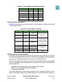
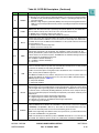
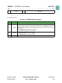
Table 8-10 PLPRCR Bit Descriptions (Continued)
Bit(s)
Name
15
SPLS
16
SPLSS
Description
System PLL lock status bit
0 = SPLL is currently not locked
1 = SPLL is currently locked
SPLL lock status sticky bit. An out-of-lock sets the SPLSS bit. The bit remains set until software clears it by writing a one to it. A write of zero has no effect on this bit. The bit is cleared
at power-on reset. This bit is not affected due to a software initiated loss-of-lock (MF change
and entering deep-sleep or power-down mode). The SPLSS bit is not affected by hard reset.
0 = SPLL has remained in lock
1 = SPLL has gone out of lock at least once (not due to software-initiated loss of lock)
Timer expired status bit. This bit controls whether the chip negates the TEXP pin in deepsleep mode, thus enabling external circuitry to switch off the VDD (power-down mode).
When LPM = 11, CSRC = 0, and TEXPS is high, the TEXP pin remains asserted. When LPM
= 11, CSRC = 0, and TEXPS is low, the TEXPS pin is negated.
17
TEXPS
To enable automatic wake-up TEXPS is asserted when one of the following occurs:
• The PIT is expired
• The real-time clock alarm is set
• The time base clock alarm is set
• The decrementer exception occurs
The bit remains set until software clears it by writing a one to it. A write of zero has no effect
on this bit. TEXPS is set by power-on or hard reset.
0 = TEXP is negated in deep-sleep mode
1 = TEXP pin remains asserted always
18
—
19
TMIST
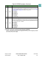
20
—
21
CSRC
22:23
24
25
Reserved
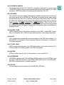
Timers interrupt status.TMIST is set when an interrupt from the RTC, PIT, TB or DEC occurs.
The TMIST bit is cleared by writing a one to it. Writing a zero has no effect on this bit. The
system clock frequency remains at its high frequency value (defined by DFNH) if the TMIST
bit is set, even if the CSRC bit in the PLPRCR is set (DFNL enabled) and conditions to switch
to normal-low mode do not exist. This bit is cleared during power-on or hard reset.
0 = No timer expired event was detected
1 = A timer expire event was detected
Reserved
Clock source. This bit is cleared at hard reset.
0 = General system clock is determined by the DFNH value
1 = General system clock is determined by the DFNL value
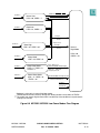
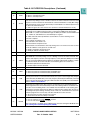
LPM
Low-power mode select. These bits are encoded to provide one normal operating mode and
four low-power modes. In normal and doze modes, the system can be in high state (frequency determined by the DFNH bits) or low state (frequency defined by the DFNL bits). The LPM
field can be write-protected by setting the LPM and CSRC lock (LPML) bit in the PLPRCR
Refer to Table 8-4 and Table 8-5.
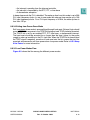
CSR
Checkstop reset enable. If this bit is set, then an automatic reset is generated when the
RCPU signals that it has entered checkstop mode, unless debug mode was enabled at reset.
If the bit is clear and debug mode is not enabled, then the USIU will not do anything upon
receiving the checkstop signal from the RCPU. If debug mode is enabled, then the part enters debug mode upon entering checkstop mode. In this case, the RCPU will not assert the
checkstop signal to the reset circuitry. This bit is writable once after soft reset.
0 = No reset will occur when checkstop is asserted
1 = Reset will occur when checkstop is asserted
LOLRE
Loss of lock reset enable
0 = Loss of lock does not cause HRESET assertion
1 = Loss of lock causes HRESET assertion
Note: if limp mode is enabled, use the COLIR feature instead of setting the LOLRE bit. See
8.12.3 Change of Lock Interrupt Register (COLIR).
MPC555 / MPC556
CLOCKS AND POWER CONTROL
USER’S MANUAL
Rev. 15 October 2000
MOTOROLA
8-33