1
8.2 System Clock Sources
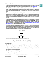
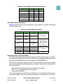
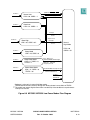
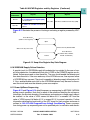
The system clock can be provided by the main system oscillator (OSCM), an external
clock input, or the backup clock (BUCLK) on-chip ring oscillator, see Figure 8-2.
The OSCM uses either a 4-MHz or 20-MHz crystal to generate the PLL reference
clock. When the main system oscillator output is the timing reference to the system
PLL, skew elimination between the XTAL/EXTAL pins and CLKOUT is not guaranteed.
The external clock input receives a clock signal from an external source. The clock frequency must be either in the range of 3 MHz – 5 MHz or at the system frequency of at
least 15 MHz (1:1 mode). When the external clock input is the timing reference to the
system PLL skew elimination between the EXTCLK pin and the CLKOUT is less than
± 1 ns.
The backup clock on-chip ring oscillator enables the MCU to function with a less precise clock. When operating from the backup clock, the MCU is in limp mode. This enables the system to continue minimum functionality until the system is fixed. The
BUCLK frequency is approximately 7 MHz (see APPENDIX G ELECTRICAL CHARACTERISTICS for the complete frequency range).
For normal operation, at least one clock source (EXTCLK or OSCM) must be active.
A configuration with both clock sources active is possible as well. At this configuration
EXTCLK provides the OSCCLK and OSCM provides the PITRTCLK. The input of an
unused timing reference (EXTCLK or EXTAL) must be grounded.
XTAL
EXTAL
1 MΩ*
CL
CL
*Resistor is not currently required on the board but space should be available for its addition in the future.
Figure 8-2 Main System Oscillator (OSCM)
8.3 System PLL
The PLL allows the processor to operate at a high internal clock frequency using a low
frequency clock input, a feature which offers two benefits. Lower frequency clock input
reduces the overall electromagnetic interference generated by the system, and the
ability to oscillate at different frequencies reduces cost by eliminating the need to add
an additional oscillator to a system.
The PLL can perform the following functions:
• Frequency multiplication
MPC555 / MPC556
CLOCKS AND POWER CONTROL
USER’S MANUAL
Rev. 15 October 2000
MOTOROLA
8-3