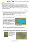
1
Caution Ensure all tie wraps/Velcro (or similar) securing any of the sections in place are removed prior to operation. Otherwise damage to the frame could occur. 5.3 Fitting the electrical system Remove black dust caps from the 5 middle actuator ports, leaving the outer 2 in place (see bottom left image). Plug the actuator and handset cables into the control box. The cables are colour matched to the graphic on the control box, using this plug the cables into the corresponding ports. Note, the plugs only fit into the ports in one orientation. Ensure the cables are plugged fully into the control box. Note: The two bed ends are identical but plugging them into the correct port is important. Note the cable tie colour before plugging in. Once all the cables are connected they are to be secured in place by attaching the supplied anti‐removal clip. Clip the mains cable into the hook on the head end section of the bed. Mains cable clip Hi/Low ‐ Head end (Blue) Hi/Low ‐ Foot end (White) Backrest (Black) Knee Break (Yellow) Handset Anti‐removal clip Caution Ensure all cables are free from moving parts and are not under excessive tension. Ensure the two hi/low actuators are plugged into the correct ports, if not the tilt function will not work correctly. 8