1
EPE-1814V2NAR
EPE 全长主板带 VGA 和双千兆 LAN
EPE Full-size Motherboard with VGA and
Double Gigabit LAN
Version:C00
Announcement What contained in this User Manual does not represent the commitments of EVOC Company. EVOC Company reserves the right to revise this User Manual, without prior notice, and will not be held liable for any direct, indirect, intended or unintended losses and/or hidden dangers due to installation or improper operation. Before purchasing, please have a detailed understanding of the product performance to see whether it meets your requirements. EVOC is a registered trademark of EVOC Intelligent Technology Co., Ltd. All trademarks, registered trademarks, and trade names used in this User Guide are the property of their respective owners. EVOC Intelligent Technology Co., Ltd. ©2009, Copyright Reserved. No part of this manual can be reproduced in any form or by any means, such as in electronic or mechanical way, without permission in writing from EVOC. Safety Instructions 1. Please carefully read the users’ manual before handling the product; 2. For the board which is not ready to be installed, please put it in the antistatic packaging; 3. Before taking the board out from antistatic packaging, please put your hand on grounded metal object for a while (about 10 seconds) to discharge static; 4. Please wear static protective gloves when holding the board; and always hold the board by edges; 5. Before inserting, removing or reconfiguring the motherboard or the expansion card, please firstly disconnect the AC power or unplug the AC power cable from the power source to prevent damage to the product and ensure your personal safety; 6. Before removing the boards or Box PC, firstly turn off all power resources and unplug the power cable from power source; 7. For Box PC products, when inserting or removing boards, please disconnect the AC power in advance; 8. Before connecting or disconnecting any device, make sure all power cables are unplugged in advance; 9. To avoid unnecessary damage caused by turning on/off computer frequently, wait at least 30 seconds before returning on the computer.
Contents Chapter 1 Product Introduction ................................................................................1 Overview ............................................................................................................1 Mechanical Dimension, Weight and Environment.................................................1 Typical Consumption...........................................................................................2 Microprocessor ...................................................................................................2 Chipset ...............................................................................................................2 System Memory ..................................................................................................2 Video Function....................................................................................................2 Network Function................................................................................................2 Audio Function ...................................................................................................3 Power Feature .....................................................................................................3 Expansion Bus ....................................................................................................3 Watchdog Function..............................................................................................3 I/O Connector .....................................................................................................3 Chapter 2 Installation...............................................................................................4 Product Outline ...................................................................................................4 Locations of Connectors ......................................................................................5 Motherboard Structure.........................................................................................6 Jumper Setting ....................................................................................................7 Audio Connector .................................................................................................7 Video Connector .................................................................................................8 LAN Port ............................................................................................................8 Serial Port ...........................................................................................................9 Parallel Port ........................................................................................................9 IDE Connector ..................................................................................................10 SATA Connector................................................................................................11
Hotswap of SATA Hard Disk............................................................................ 11 USB Port.......................................................................................................... 13 Digital IO Connector......................................................................................... 14 Keyboard and Mouse Connector........................................................................ 14 Status Indicating and Controlling Connectors..................................................... 14 Power Connector .............................................................................................. 15 Fan Connector .................................................................................................. 15 Install the CPU ................................................................................................. 16 Install the CPU Cooling Fan.............................................................................. 16 Chapter 3 BIOS Setup ........................................................................................... 19 Overview.......................................................................................................... 19 BIOS Parameter Setup ...................................................................................... 19 Basic Function Setting for BIOS........................................................................ 20 The System Resource Managed by BIOS under x86 Platform............................. 37 Chapter 4 Install the Driver.................................................................................... 41 Appendix.............................................................................................................. 42 Watchdog Programming Guide.......................................................................... 42 Digital I/O Programming Guide ........................................................................ 44 Way and Steps for RAID Installation ................................................................. 47
Chapter 1 Product Introduction
Chapter 1 Product Introduction Overview EPE1814V2NAR is a sort of highperformance fullsize CPU card which adopts EPE specification (compatible with PICMG1.3 bus specification) and supports dualcore/quadcore CPU and DDR3 memory; the latest EPE specification enables the stability of the card better than the PICMG1.3 motherboard. The product adopts Intel® 4 series embedded platform: technique scheme realization of Intel® G41 + ICH7R. Integrate VGA display, support DVMT mode with shared memory up to 352MB; onboard two DDR3 memory slots, support dualchannel DDR3 800/1066MHz up to 4GB; eight USB2.0 ports (four on motherboard and the other four are educed via the carrier), two RS232 COMs, one parallel port, two Gigabit LAN ports, four SATA connectors (two on motherboard and the other two are educed via the carrier), one IDE connector, one PS/2 keyboard and mouse connector, one 8bit digital I/O; support HD Audio connector, MICin, Linein and Speakerout. Mechanical Dimension, Weight and Environment Ø Dimension: 338.6 mm (L) × 129.7 mm (W) × 35mm (H) Ø Net Weight: 496.9g Ø Operating Environment: Temperature: 0°C ~ 60°C; Humidity: 5% ~ 90% (Noncondensing); Ø Storage Environment: Temperature: 20°C ~ 80°C; Humidity: 5% ~ 90% (Noncondensing);
EPE1814V2NAR 1 Chapter 1 Product Introduction Typical Consumption CPU: Intel Core 2 Quad Q9300 1333 2.5GHz 95W Memory: Kingston/1333/2G*2 Ø +5V@ 1.47A; +5%/3%; Ø +3.3V@ 1.75A; +5%/3%; Ø +12V@ 1.07A; +5%/3%; Microprocessor Support Intel® LGA775 socket Core TM 2 Quad ,Core TM 2 Duo, Celeron® E1000 and Celeron®400 series CPU, 800/1066/1333MHz FSB. Not support Intel® Core™2 Extreme, Pentium® 4, Pentium® D and Celeron® D series CPU. Chipset Intel® G41 + Intel® ICH7R System Memory Provide two 240 Pin DDR3 memory slots, support DDR3 800/1066MHz Unbuffered nonECC memory up to 4GB; Video Function Intel® G41 North Bridge chip integrates VGA display with maximum resolution up to 2048 X 1536@75Hz. Network Function Provide two 10/100/1000Mbps network ports; LAN1 supports WakeonLAN function.
2 EPE1814V2NAR Chapter 1 Product Introduction
Audio Function Adopt ALC888 sound effect chip, it supports MICin, Linein and Speakerout functions. Power Feature Adopt ATX power, support ACPI S0/S1/S4/S5 status, etc. Expansion Bus Adopt EPE bus specification; support one PCIE x16, four PCIE x1 or one PCIE x4, four USBs, two SATAs, SMBUS and four PCI master expansions. Watchdog Function Ø Support 255 levels, programmable, by minute or second; Ø Support watchdog interrupt or reset system. I/O Connector Ø One parallel port; Ø Two COMs, COM1 supports Wakeup function; Ø One IDE connector; Ø Four SATA connectors (two of which are educed via carrier), support RAID0, 1, 5 and 10; Ø Eight USB2.0 ports (four of which are educed via carrier); Ø One PS/2 keyboard/mouse connector; Ø One 8bit digital I/O connector.
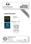
EPE1814V2NAR 3 Chapter 2 Installation Chapter 2 Installation Product Outline 129.7
5.4
8.6
23
H1 H5
H3
8.6
120
175
H10
H7
H9
338.6
H8
H4
H2
H6 16.6
10.5
14.7
Unit: mm
4 EPE1814V2NAR 3.8
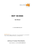
Chapter 2 Installation Locations of Connectors FP1
PWR1
CPUFAN1
FP3
FP2
DIMM1
DIMM2
GPIO1
IDE1
SYSFAN1
SATA2 SATA1
USB2
USB1
COM1 COM2
JCC1
LPT1
AUDIO1
KM1
LAN2
VGA1
EPE1814V2NAR LAN1
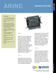
5 Chapter 2 Installation Motherboard Structure LGA775 Processor FSB Bus VGA DDR3 GMCH Display Interfa ce CH A G41 DIMM1 DDR3 PCIE x16 CH B DIMM2 DMI PCIE x4 EPE Connector SATA3~4 SATA Port 1~2 SAT A ICH7R USB PORT 0~3 USB 2.0 USB PORT 4~7 USB 2.0 PATA Port PAT A PCIE Port5 RTL8111D PCIE Port 6 RTL8111D LAN1 RJ45 Connector LAN2 RJ45 Connector NH82801GR PCIE x4
HDA Audio Fan Control
Ha rdware Monitor SPI L PC Bu s PCI BUS HDA LPC SIO SPI Flash Fan Co ntr ol Ke yboard COM1 Mouse 6 EPE1814V2NAR COM2 Para llel Chapter 2 Installation Tip: How to identify the first pin of the jumpers and connectors? 1. Observe the letter beside the socket, it would be marked with “1” or thickened lines or triangular symbols; 2. The square pad on the rear is the first pin; 3. The red line on the cable or other marks show that they should be connected with the first pin of the socket. Jumper Setting JCC1: Clear/Keep CMOS Setting (Pin Distance: 2.54 mm) CMOS is powered by the button battery on board. Clear CMOS will restore original settings (factory default). The steps are listed as follows: (1) Turn off the computer and unplug the power cable; (2) Instantly short circuit JCC1; (3) Turn on the computer; (4) Follow the hint on screen to enter BIOS setup when starting the computer, load optimized defaults; (5) Save and exit. Please setup as follows: JCC1 Setup Function 12 Open Normal (Default) 12 Short Clear the contents of CMOS, all BIOS setting will restore to factory default values. Audio Connector AUDIO1 (Pin Distance: 2.54mm) Pin Signal Name Pin Signal Name 1 LOUT_R 2 LOUT_L 3 GND_AUDIO 4 GND_AUDIO 5 LIN_R 6 LIN_L 7 GND_AUDIO 8 GND_AUDIO 9 MIC_L 10 MIC_R
EPE1814V2NAR 7 Chapter 2 Installation Video Connector 15Pin DSub VGA socket, VGA1. VGA1 Pin Signal Name Pin Signal Name 1 Red 2 Green 3 Blue 4 NC 5 GND 6 GND 7 GND 8 GND 9 +5V 10 GND 11 NC 12 DDCDATA 13 HSYNC 14 VSYNC 15 DDCCLK LAN Port The board provides two 10/100/1000Mbps Ethernet ports; LILED and ACTLED are the two LED indicators beside Ethernet ports, which respectively show the activity and transmitting status of LAN. Please refer to the status descriptions for each LED: LAN1/LAN2 ACTLED LAN Activity (Green) Indicator LILED LAN Speed (Dual Color: Y/G) Indicator Green 1000Mbps Blink Data Transmitting Yellow 100Mbps Off No Data to Transmit Off 10Mbps
8 EPE1814V2NAR Chapter 2 Installation Serial Port The board provides two 2×5Pin serial ports (Pin Distance: 2.54 mm), they support RS232 modes and the pin definitions are as follows: COM1/2 Pin Signal Name Pin Signal Name 1 DCD# 6 DSR# 2 RXD 7 RTS# 3 TXD 8 CTS# 4 DTR# 9 RI# 5 GND 10 NA Parallel Port The board provides one standard 2×13Pin parallel port (Pin Distance: 2.54 mm), it could connect with peripheral devices with parallel port according to requirements. The pin definitions are as follows: LPT1 Pin Signal Name Pin Signal Name 1 STB# 2 AFD# 3 PD0 4 ERR# 5 PD1 6 INIT# 7 PD2 8 SLIN# 9 PD3 10 GND 11 PD4 12 GND 13 PD5 14 GND 15 PD6 16 GND 17 PD7 18 GND 19 ACK# 20 GND 21 BUSY 22 GND 23 PE 24 GND 25 SLCT 26 NC
EPE1814V2NAR 9 Chapter 2 Installation IDE Connector The board provides one standard 2×20Pin IDE connector (Pin Distance: 2.54 mm), it supports Ultra100/66/33 BMIDE and PIO mode. The pin definitions are as follows: IDE1 10 Pin Signal Name Pin Signal Name 1 RESET# 2 GND 3 D7 4 D8 5 D6 6 D9 7 D5 8 D10 9 D4 10 D11 11 D3 12 D12 13 D2 14 D13 15 D1 16 D14 17 D0 18 D15 19 GND 20 Key 21 DREQ 22 GND 23 IOW# 24 GND 25 IOR# 26 GND 27 IORDY 28 GND 29 DACK# 30 GND 31 IRQ 32 NC 33 DA1 34 ATA66_DET 35 DA0 36 DA2 37 CS1# 38 CS3# 39 LED# 40 GND
EPE1814V2NAR Chapter 2 Installation SATA Connector The board supports four SATA connectors, two of which are educed via carrier. The pin definitions of the two standard connectors on motherboard are listed as follows: SATA1/2 Pin Signal Name 1 GND 2 TX+ 3 TX 4 GND 5 RX 6 RX+ 7 GND Hotswap of SATA Hard Disk Notices for Hotswap of SATA Hard Disk: 1. The hard disk shall support SATA 2.0 and use 15pin SATA hard disk power connector. 2. The driver of chipset shall support the hotswap of SATA hard disk. 3. Hotswap of SATA hard disk with the operating system is forbidden when system is poweron. SATA Data Cable SATA Power Cable
Please carry out hot plug as follows, improper operation may destroy the hard disk or result in data lost. Hot Plug EPE1814V2NAR 11 Chapter 2 Installation Step 1: Please plug the 1 x 4 pin SATA power connector (white) into the power adapter. Step 2: Please connect the SATA data cable to the SATA connector on the board. Step 3: Please connect the 15pin SATA power connector (black) to the SATA hard disk. Step 4: Please connect the SATA data cable to the SATA hard disk.
12 EPE1814V2NAR Chapter 2 Installation Hot Unplug Step 1: uninstall the hard disk from the device manager. Step 2: Unplug the data cable from the SATA hard disk. Step 3: Unplug the SATA 15pin power connector (black) from the SATA hard disk. USB Port The board supports eight USB ports, four of which are educed out via carrier. The board provides two sets of standard USB ports (Pin Distance: 2.54 mm), which could educe out four USB ports. The pin definitions are as follows: USB1/2 Pin Signal Name Pin Signal Name 1 +5V 2 +5V 3 USB1_Data 4 USB2_Data 5 USB1_Data+ 6 USB2_Data+ 7 GND 8 GND 9 NA 10 GND
EPE1814V2NAR 13 Chapter 2 Installation Digital IO Connector The board provides one 8bit digital I/O connector (Pin Distance: 2.00 mm); the pin definitions are as follows: GPIO1 Pin Signal Name Pin Signal Name 1 DIO_IN0 2 DIO_OUT0 3 DIO_IN1 4 DIO_OUT1 5 DIO_IN2 6 DIO_OUT2 7 DIO_IN3 8 DIO_OUT3 9 GND 10 NC Keyboard and Mouse Connector Keyboard and mouse connector KM1 Pin Signal Name 1 KB_DATA 2 MS_DATA 3 GND 4 +5V 5 KB_CLK 6 MS_CLK Status Indicating and Controlling Connectors FP1, FP2 and FP3 are used to connect with the function button or indicators on front panel of the chassis. ATX Power Switch and Hard Disk Indicator Connector (Pin Distance: 2.54 mm) FP1 14 Pin Signal Name Pin Signal Name 1 PWRBTN# 2 GND 3 GND 4 RESET# 5 HDD_LED 6 HDD_LED+
EPE1814V2NAR Chapter 2 Installation Power Indicator Connector (Pin Distance: 2.54 mm) Pin Signal Name 1 PWR_LED+ 2 NC 3 GND FP2 Loudspeaker Output Connector (Pin Distance: 2.54 mm) Pin Signal Name 1 SPEAKER 2 NC 3 GND 4 +5V FP3 Power Connector +12V Power Connector (Pin Distance: 4.20 mm) PWR1 Pin Signal Name 1 GND 2 GND 3 +12V 4 +12V Fan Connector The CPU card provides two sets of standard fan sockets (Pin Distance: 2.50 mm). Pay attention as following three issues when using the fan sockets: Ø The current for fan shall not be over 700 mA (12V); Ø Please confirm that the fan cable complies with the socket cable. Power cable (usually red) is in the middle position. In addition, please confirm the earth
EPE1814V2NAR 15 Chapter 2 Installation cable (usually black) and fan speed output impulse signal cable (other colors). Some fans have no speed detecting while the output of the cable is up to 12V, usage of these substandard connection will destroy the CPU card. It is recommended to use a fan with speed detection. Ø Adjust the fan’s airflow to the direction of heat venting. CPUFAN1/ SYSFAN1 Pin Signal Name 1 GND 2 +12V 3 FAN_IO 4 FAN_PWM FAN_IO: Fan Speed Impulse Output; FAN_PWM: Fan Speed PWM Control Install the CPU Please install the CPU as follows (Refer to the figure below): Ø Aim the concave of the CPU at the heave mark on the CPU socket; then put the CPU in the socket; Ø After the CPU is installed properly, cover the CPU via the upper cover of the CPU socket; then fasten the CPU with hooks. Install the CPU Cooling Fan Please install the CPU cooling fan as follows (Refer to the figure below): Ø Firstly, aim the bracketof the cooling fin (see figure ④) at the fixing holes on
16 EPE1814V2NAR Chapter 2 Installation the rear of the CPU card; Ø Connect the front side of cooling fin (see figure ⑤) with the bracketand fix them; pay attention that the surface between the cooling fin and the CPU crystal wafer shall be well contacted; Ø Fix the cooling fin with two screws on the cross (do not tighten them) and then the other two screws; then tighten the four screws; Ø Lastly, connect the fan power cable to the fan socket on the CPU card. Note! 1) It is recommended to use cooling fan authenticated by Intel; before installing the fan, smear the heat sink compound on the surface between CPU and the fan cooling fin to improve the heat dissipation performance; always check whether the fan is operating normally to ensure the heat dissipation within the chassis. When holding a board, please hold the edge instead of the cooling fin. 2) When assembling the computer, please fix the attached cooling fin bracket to the chassis, so as to reinforce and guarantee the stability of the system. The installation figure is shown as follows:
EPE1814V2NAR 17 Chapter 2 Installation Steps: 1. Fix the cooling fin bracket with PCB via two screws at the locations of H1 and H3; 2. Fix the four screws on cooling fin with the cooling fin bracket. Notes: 1: Do not tighten the screws at H1 and H3 until the four screws on cooling fin are well contacted with the rivet holder of the cooling fin bracket; 2. When tightening the four screws on cooling fin, tighten them in diagonal sequence instead of one at a time or the screws at the same side.
18 EPE1814V2NAR Chapter 3 BIOS Setup Chapter 3 BIOS Setup Overview BIOS (Basic Input and Output System) is solidified in the flash memory on the CPU board. Its main functions include: initialize system hardware, set the operating status of the system components, adjust the operating parameters of the system components, diagnose the functions of the system components and report failures, provide hardware operating and controlling interface for the upper level software system, guide operating system and so on. BIOS provides users with a humancomputer interface in menu style to facilitate the configuration of system parameters for users, control power management mode and adjust the resource distribution of system device, etc. Setting the parameters of the BIOS correctly could enable the system operating stably and reliably; it could also improve the overall performance of the system at the same time. Inadequate even incorrect BIOS parameter setting will decrease the system operating capability and make the system operating unstably even unable to operate normally. BIOS Parameter Setup Prompt message for BIOS setting may appear once powering on the system. At that time (inefficient at other time), press the key specified in the prompt message (usually <Del>) to enter BIOS setting. When the BIOS setting in CMOS is destroyed, system may also require entering BIOS setting or selecting certain default value. All the setup values modified by BIOS are saved in the CMOS storage in system. The CMOS storage is powered by battery; unless clearing CMOS contents, or else its contents will not be lost even if powered off. Note! BIOS setting will influent the computer performance directly. Setting parameter improperly will cause damage to the computer; it may even unable to power on. Please use the internal default value of BIOS to restore the system. Our company is constantly researching and updating BIOS, its setup interface may be a bit different. The figure below is for reference only; it may be different from your BIOS setting in use.
EPE1814V2NAR 19 Chapter 3 BIOS Setup Basic Function Setting for BIOS After starting SETUP program, the main interface of CMOS Setup Utility will appear: Phoenix – AwardBIOS CMOS Setup Utility „ „ „ „ „ „ „ Standard CMOS Features Advanced BIOS Features Advanced Chipset Features Integrated Peripherals Power Management Setup PnP/PCI Configurations PC Health Status Esc : Quit F10 : Save & Exit Setup Load FailSafe Defaults Load Optimized Defaults Set Supervisor Password Set User Password Save & Exit Setup Exit Without Saving ←→↑↓ : Select Item Time, Data, Hard Disk Type... u Standard CMOS Features Standard CMOS Features Date (mm:dd:yy) Fri,Jan 12 2007 Time (hh:mm:ss) 19 1 9:18:17 Item Help Menu Level „ „ „ „ „ „ IDE Channel 0 Master [None] IDE Channel 0 Slave [None] IDE Channel 1 Master [None] IDE Channel 1 Slave [None] IDE Channel 2 Master [None] IDE Channel 3 Master [None] Change the internal clock.
Drive A [1.44M, 3.5 in] Video [EGA/VGA] Halt On [All Errors] Base Memory 639K Extended Memory 487424K Total Memory 488448K 20 EPE1814V2NAR Chapter 3 BIOS Setup Ø Date Choose this option and set current data by PageUp /PageDown, which is displayed in format of month/date/year. Reasonable range for each option is: Month (Jan.Dec.), Date (0131), Year (Maximum to 2099), Week (Mon. ~ Sun.). Ø Time Choose this option and set current time by PageUp /PageDown which is displayed in format of hour/minute/second. Reasonable range for each option is: Hour (0023), Minute (0059), Second (0059). Ø IDE Channel 0 Master The four options: IDE Channel 0 Master/Slave, IDE Channel 1 Master/Slave, IDE Channel 2 Master and IDE Channel 3 Master indicate that the motherboard integrates four sets of IDE channels on board; channel 0 and channel 1 could connect with two devices (master/slave); channel 2 and channel 3 could connect with one IDE master device respectively. When there is no IDE device detected, it will show [None]; if there are IDE devices detected, it will show the name of the device. IDE Channel 0 Master IDE HDD AutoDetection [Press Enter] Item Help Menu Level IDE Channel 0 Master [Auto] Access Mode [Auto] Capacity 0 MB To autodetect the HDD’s size, head...on this channel Cylinder 0 Head 0 Precomp 0 Landing Zone 0 Sector 0 Take IDE Channel 0 Master as an example, the newly appeared menu includes the following options:
EPE1814V2NAR 21 Chapter 3 BIOS Setup l IDE HDD AutoDetection This option allows detecting the parameters of the IDE device via pressing Enter, and these parameters will automatically be displayed at the bottom of the screen. l IDE Channel 0 Master The default value is Auto; system will automatically detect which IDE device it is; select “Manual” means that users have to input all these parameters manually (it is not recommended unless the user is quite familiar with all these parameters). Select “None” to disable that channel. l Access Mode The default value is Auto; In CHS option, “C” represents Cylinder, “H” represents Head, “S” represents Sector; while the “Large” option represents extended CHS. In early times, by adding transmission in BIOS layer, the hard disk addressing exceeds the bottleneck of 512M. LBA option abandons the specifications of column, channel and sector and takes sector as unified addressing for all the hard disks. To choose this option, it requires both the BIOS and hard disk to support LBA mode. Auto means that system will decide the way of accessing the hard disks. Capacity: current capacity of the hard disk Cylinder: number of the hard disk cylinder Head: number of the read/write head Precomp: write in the precompensation value to adjust writein time Landing zone: landing zone of read/write head Sector: sector number of each track Ø Drive A <Drive A> means 1.44M, 3.5″ floppy disk. Ø Video There are four displaying modes in <Video> option, EGA/VGA: EGA (Enhanced Graphics Adapter), each pixel is 4bits, 16 colors in all and support resolution of
22 EPE1814V2NAR Chapter 3 BIOS Setup 640*350. VGA (Video Graphics Array) supports 16 colors, resolution 640*480 and 256 colors, resolution 320*200. CGA40/CGA80: CGA (Color Graphics Adapter) supports 4 colors, resolution 320*200. 40 and 80 represent to display in 40 and 80 rows respectively. MONO: single color display. Ø Halt On <Halt On>: set the interrupt location for system selftest. All Errors: during POST phase, BIOS will stop selftest whenever there is an error. No Errors: BIOS ignores the error and continues selfinspection. All, But Keyboard: during POST phase, skip the inspection for keyboard. Base Memory Extended Memory Total Memory u Advanced BIOS Features Advanced BIOS Features „ CPU Feature [Press Enter] „ Hard Disk Boot Priority [Press Enter] Virus Warning [Disabled] CPU L3 Cache [Enabled] Quick Power On Self Test [Enabled] First Boot Device [Hard Disk] Second Boot Device [CDROM] Third Boot Device [LS120] Boot other Device [Enabled] Boot Up NumLock Status [On] Typematic Rate Setting [Fast] Typematic Rate(Chars/Sec) [Disabled] Typematic Delay(Msec) 6 Security Option 250 APIC Mode [Setup] Small Logo(EPA) Show [Disabled] Auto Detect PCI CLK [Enabled] Spread Spectrum [Enabled] EPE1814V2NAR Item Help Menu Level
23 Chapter 3 BIOS Setup Ø CPU Feature CPU Feature PPM Mode [Native Mode] Limit CPUID MaxVal [Disabled] C1E Function [Auto] Execute Disable Bit [Enabled] Virtualization Technology [Disabled] Core MultiProcessing [Enabled] Item Help Menu Level Native Mode is for fully support ACPI OS (ex.WINXP, VISTA...), SMM mode is for legacy OS (ex. Win2K) l PPM Mode That is EIST (Enhanced Intel Speedstep Technology); it is a module to adjust the basic frequency and voltage according to the load of the processor, which requires supports from both OS and BIOS; system will adjust via ACPI. Speedstep Technology provides more adjusting levels for CPU frequency and voltage; therefore, it could adjust the status of the processor more accurately than C1E. Native Mode: applied in the OS supporting ACPI completely, such as: WINXP, and VISTA (Default) SMM Mode: applied in the traditional OS, such as: WIN2000. l Limit CPUID MaxVal This option could be enabled to support the maximum limitation function of CPUID in former operating system, so as to prevent CPU from returning a value above 3 after implementing CPUID command and cause system error. Disabled: this option shall be disabled under WINXP system. (Default) Enabled l C1E Function The function of this option is similar with that of EIST. When enabled, it could make the unloaded CPU operate under the lowest frequency multiplication supported by CPU. However, from power saving point of view, the effect is no better than EIST option.
24 EPE1814V2NAR Chapter 3 BIOS Setup Disabled Auto: BIOS automatic detection (Default) l Execute Disable Bit Hardware antivirus technique is a function educed into new generation processor by Intel. Enabling this function could prevent virus, Trojan and so on from destroying the system memory and control the system. The basic operating principle is that the processor will divide several areas in memory, part of the areas are allowed to implement application code while other areas are not allowed. Disabled Enabled (Default) <Virtualization Technology>: virtualization technology Disabled (Default) Enabled l Core MultiProcessing Multicore processor. If it is disabled, only one core is operating. Disabled Enabled (Default) Ø Hard Disk Boot Priority When the host is connected with several hard disks, choose this option; press “Enter” and you’ll see the hard disk list; the hard disk at the top of the list is the one to be boot; using “pagedown” and “pageup” to adjust the sequence. <Bootable Addin Cards> represents the boot hard disk in expansion card. Ø Virus Warning After enabling this option, the booting area of the IDE hard disk is under protection. If certain program is trying to write data into the booting area, BIOS will show warning information on the screen and the buzzer will alarm. Disabled (Default) Enabled Ø CPU L3 Cache Enable CPU L3 cache.
EPE1814V2NAR 25 Chapter 3 BIOS Setup Disabled Enabled (Default) Ø Quick Power On Self Test If this function is enabled, certain tests during booting may be skipped to reduce booting time. Disabled Enabled (Default) Ø First Boot Device First boot device LS120: 120M floppy driver, it could take 120M floppy disk as boot disk. Hard Disk: take hard disk as boot disk. (Default) CDROM: CDROM, it could take CD as boot disk. ZIP100: 100M floppy disk driver USBFDD: floppy disk driver of USB port USBZIP: take USBZIP as the first boot device USBCDROM: CDROM of USB port Legacy LAN: take the network card as boot devices Disabled: disable this function Ø Second Boot Device Second boot device Ø Third Boot Device Third boot device Ø Boot other Device This option is used to boot the computer by other devices, when the foresaid devices cannot start up the computer successfully. Disabled Enabled (Default) Ø Boot Up NumLock Status This option can be set to “On” or “Off”. When it is set to “On”, it means to enable the “NumLock” key automatically during system booting. Off
26 EPE1814V2NAR Chapter 3 BIOS Setup On (Default) Ø Typematic Rate Setting This option can be set to “Enabled” or “Disabled”. When it is set to “Enabled”, if press certain key without release, the computer will regard that you’ve pressed the key repeatedly. When it is set to “Disabled”, if press certain key without release, Disabled (Default) Enabled Ø Typematic Rate(Chars/Sec) If “Typematic Rate Setting” is set to “Enabled”, then you may set to press certain key for one second equals to pressing the key for several times via this option. Ø Typematic Delay (Msec) If “Typematic Rate Setting” is set to “Enabled”, then you may set to press certain key and then regard as pressing this key repeatedly after certain time delay via this option; the unit is ms. Ø Security Option When chosen “system”, it will prompt to enter password when booting; when chosen “setup”, it will prompt to enter password when entering BIOS setup. System Setup: enter “Setup” interface. (Default) Ø APIC Mode Enable or disable APIC Disabled Enabled (Default) Ø Small Logo (EPA) Show When this option is enabled, it is to display the energy star logo of EPA during booting. Disabled (Default) Enabled Ø Auto Detect PCI CLK
EPE1814V2NAR 27 Chapter 3 BIOS Setup Enabled: automatically detect all the PCI and AGP slots; if no inserted cards are occupying that slot, disable the clock signal for that slot to reduce EMI. (Default) Disabled: no matter the slots are used or not, all the clock signals are provided normally. Ø Spread Spectrum <Disabled>: disable Spread Spectrum function for system. <Enabled>: extend clock frequency for the system to reduce EMI. (Default) u Advanced Chipset Features Advanced Chipset Features Memory Hole At 15M16M [Disabled] Disable MCHBAR MMIO [Enabled] VTd [Disabled] Item Help Menu Level ** VGA Setting ** PEG/Onchip VGA Control OnChip Frame Buffer Size DVMT Mode Total GFX Memory PAVP Mode Ø Memory Hole At 15M16M By enabling this function, users may reserve this portion of the address space 15M16M for ISA device; therefore, the system address may decrease. Disabled (Default) Enabled Ø Disable MCHBAR MMIO By enabling this function, users may release the MMIO space of the North Bridge after BIOS POST ends. Disabled Enabled Default) Ø PEG/Onchip VGA Control
28 EPE1814V2NAR Chapter 3 BIOS Setup This option chooses to use the onchip graphic controller or video card with PCIE slot when booting the system. Onchip VGA: onchip graphic processor; PEG Port: external video card with PCIE slot; Auto: BIOS Automatic Detection Selection. (Default) Ø OnChip Frame Buffer Size This option chooses the system memory resource size assigned to the Graphics Media Accelerator. The options are: 32MB (Default), 64M and 128MB. Ø DVMT Mode Dynamic Video Memory Technology. By enabling this function, users may assign system memory to integrated video card dynamically. Disabled Enabled (Default) Ø Total GFX Memory Under Windows XP, the maximum value of GFX memory is based on the size of the system memory. For example, the system memory is 1GB, the maximum GFX video memory 512MB\ 128MB (Default)\ 256MB Ø PAVP Mode Protected Audio/Video Path mode Disabled (Default) Enabled u Integrated Peripherals Integrated Peripherals „ OnChip IDE Device „ SuperIO Device Item Help Menu Level
OnChip Audio Device [Enabled] „ USB Device Setting EPE1814V2NAR 29 Chapter 3 BIOS Setup Ø OnChip IDE Device OnChip IDE Device IDE HDD Block Mode [Enabled] IDE DMA transfer access [Enabled] IDE Primary Master PIO [Auto] IDE Primary Slave PIO [Auto] IDE Primary Master UDMA [Auto] IDE Primary Slave UDMA [Auto] Item Help Menu Level If your IDE hard drive supports block mode select OnChip Secondary PCI IDE [Enabled] Enabled for automatic IDE Secondary Master PIO [Auto] detection of the optimal IDE Secondary Slave PIO [Auto] number of block IDE Secondary Master UDMA [Auto] read/writes per sector the IDE Secondary Slave UDMA [Auto] drive can support LEGACY Mode Support [Disabled] l IDE HDD Block Mode By enabling this function, it could transmit data from several sectors in one interrupt. All of the main stream hard disks support this function and it is recommended to set it to “Enabled”. Disabled Enabled (Default) l IDE DMA transfer access This option enables the DMA function of the IDE device. Disabled Enabled (Default) l IDE Primary Master PIO This option represents the PIO mode selection for the master hard disk in IDE channel 1.
30 EPE1814V2NAR Chapter 3 BIOS Setup PIO Mode Cycle Time Transfer Rate Standard Mode 0 600 3.3 (MB/S) ATA Mode 1 383 5.2 (MB/S) ATA Mode 2 240 8.3 (MB/S) ATA Mode 3 180 11.1 (MB/S) ATA2 Mode 4 120 16.7 (MB/S) ATA2 Auto: BIOS Automatic Detection Selection. (Default) l IDE Primary Slave PIO This option represents the PIO mode selection for the slave hard disk in IDE channel 1. l IDE Primary Master UDMA This option enables the Ultra DMA data transmitting mode of the master hard disk in IDE channel 1. The differences between Ultra DMA and common DMA are: under Ultra DMA mode, data are transmitted both in rising edge and descending edge of the clock; under the same time frequency, its speed is twice that of DMA. Disabled Auto: BIOS Automatic Detection Selection. (Default) l IDE Primary Slave UDMA The same as above. l OnChip Secondary PCI IDE This option chooses whether to use the second IDE channel on South Bridge. Disabled Enabled (Default) l IDE Secondary Master PIO This option represents the PIO mode selection of the master hard disk on IDE channel 2. l IDE Secondary Slave PIO
EPE1814V2NAR 31 Chapter 3 BIOS Setup This option represents the PIO mode selection of the slave hard disk on IDE channel 2. l IDE Secondary Master UDMA This option enables the Ultra DMA data transmitting mode of the master hard disk on IDE channel 2. l IDE Secondary Slave UDMA This option enables the Ultra DMA data transmitting mode of the slave hard disk on IDE channel 2. l LEGACY Mode Support This option enables the software, data or OS that can support legacy version. Disabled (Default) Enabled Ø Super IO Device Super IO Device OnBoard FDC Controller [Enabled] OnBoard Serial Port 1 [3F8/IRQ4] OnBoard Serial Port 2 [2F8/IRQ3] OnBoard Parallel Port [3F8/IRQ7] Parallel Port Mode [Normal] l Item Help Menu Level <OnBoard FDC Controller> Used to enable floppy disk driver controller. l <OnBoard Serial Port 1> Set the address and IRQ of COM1 on motherboard. l OnBoard Serial Port 2 Set the address and IRQ of COM2 on motherboard. l OnBoard Parallel Port Set the address of the parallel port on motherboard and the default value is 378. l 32 Parallel Port Mode
EPE1814V2NAR Chapter 3 BIOS Setup This option sets the operating mode for the specified parallel port: Normal, ECP, EPP, SPP; ECP + EPP represent the maximum speed for bidirection data transmission; ECP represents the speed for bidirection data transmission faster than EPP. Ø OnChip Audio Device This option selects whether to enable the audio card controller integrated on chip. Ø USB Device Setting USB Device Setting USB 1.0 Controller Item Help USB 2.0 Controller USB Storage Function *** USB Mass Storage Device Boot Setting *** l Menu Level [Enable] or [Disable] Universal Host Controller Interface for Universal Serial Bus. USB 1.0 Controller This option is used to select whether to enable USB1.0 controller. l USB 2.0 Controller This option is used to select whether to enable USB2.0 controller. l USB Storage Function Enable to support USB storage device. u Power Management Setup USB Device Setting ACPI Function [Enabled] Restore on AC Power Loss [Last State] Resume by Alarm [Disabled] Date(of Month) Alarm 0 Time(hh:mm:ss) Alarm 0 : 0 : 0 EPE1814V2NAR Item Help Menu Level
33 Chapter 3 BIOS Setup Ø ACPI Function This option is used to select whether to enable ACPI power management. Disabled Enabled (Default) Ø Restore on AC Power Loss Off: do not boot automatically after resuming power. (Default) On: automatically boot after resuming power. Last State: system restores its last status after resuming power. Ø Resume by Alarm This option enables Resume by Alarm function of the system; users shall set specified time first. <Disabled> (Default) <Enabled> u PnP/PCI Configurations PnP/PCI Configurations Init Display First [PCI Slot] Reset Configuration Data [Disabled] Item Help Menu Level Resources Controlled By [Auto(ESCD)] PCI/VGA Palette Snoop [Disabled] Ø Init Display First This option is used to select whether to use onboard video card or PCI video card when system boots. PCI Slot: PCI slot external video card. (Default) Onboard: onboard video card. Ø Reset Configuration Data The function of the option is to clear ESCD (Extended System Configuration Data); when the newly installed hardware conflicts with the former system, please enable this option.
34 EPE1814V2NAR Chapter 3 BIOS Setup Disabled (Default) Enabled Ø Resources Controlled By Auto (ESCD): choose this option and BIOS will automatically assign the resource of the PnP/PCI device, such as, IRQ, DMA and memory. (Default) Manual: assign various resources manually. When “Resources Controlled By” is set to <Manual>, IRQ resource can be assigned manually. IRQ 35, 7, 912, 14, 15 assigned to PCI Device: assign to PCI device (Default) Reserved Ø PCI/VGA Palette Snoop The function of this option is that when two palettes are adopted on ISA and PCI bus respectively and the colors display abnormally, please set this option to <Enabled>. Disabled (Default) Enabled u PC Health Status PC Health Status System Temperature 34℃/ 93℉ CPU Temperature 38℃/ 100℉ SYSFAN1 Speed 2136 RPM CPUFAN1 Speed 2136 RPM Vcore 1.28v V5.0 5.05v V12.0 12.09v VBAT 3.15v Item Help Menu Level u Load Failsafe Defaults The function of this option is to initialize the setup of each option to the values realizing the most fundamental and secure system function. To implement this
EPE1814V2NAR 35 Chapter 3 BIOS Setup function, choose this option and press < Enter >; messages to be confirmed will display on the screen, press < Enter > to implement this function. u Load Optimal Defaults This menu is used to input default value in system configuration. These default values are optimized and could give play to the high capability of all hardware. u Set Supervisor Password Set Supervisor Password u Set User Password Set User Password u Save & Exit Setup When you’ve finished all the modification and want to cover the former parameters, you may implement this option; the new parameter will be saved in the CMOS storage. To implement this option, choose this option and press < Enter >; press < Enter > again to exit. u Discard Changes and Exit If you do not want to save the action of modifying the setting into CMOS storage, please choose this option and press < Enter >; press < Enter > again to exit.
36 EPE1814V2NAR Chapter 3 BIOS Setup The System Resource Managed by BIOS under x86 Platform We define three types of system resources here: I/O port addresses, IRQ number and DMA number. u u DMA Level Function DMA0 DRAM Refresh DMA1 Not Assigned DMA2 Floppy Disk DMA3 Not Assigned (sometimes used for hard disk) DMA4 Used for the cascade of DMAC DMA5 Not Assigned DMA6 Not Assigned DMA7 Not Assigned APIC Advanced programmable interrupt controller. Most motherboards above P4 level support APIC and provide more than 16 interrupt sources, like IRQ16 IRQ23; some others can have up to 28 interrupt sources such has motherboard supporting PCIX. However, relevant OS are required to enable that function, and currently, only the OS above Windows 2000 could support that function. u IO Port Address There is 64K for the system I/O address space. Each external device will occupy portion of the space. The table below shows parts of the distribution of the I/O address. As the address of PCI device (e.g. PCI network card) is configured by software, it is not listed in this table.
EPE1814V2NAR 37 Chapter 3 BIOS Setup Address Device Description 000h 00Fh DMA Controller #1 000h CF7h PCI Bus 010h 01Fh Carrier Resource 020h 021h Programmable Interrupt Controller #1 022h 03Fh Carrier Resource 040h 043h System Timer 044h 05Fh Carrier Resource 060h Standard 101/102 Key or Microsoft Natural PS/2 Keyboard 061h System speaker 062h – 063h 064h Carrier Resource Standard 101/102 Key or Microsoft Natural PS/2 Keyboard 065h 06Fh Carrier Resource 070h 071h Real Time Clock, NMI 072h – 07Fh Carrier Resource 080h Carrier Resource 081h 083h DMA Controller #2 084h 086h Carrier Resource 087h DMA Controller #3 088h Carrier Resource 089h 08Bh DMA Controller #4 08Ch 08Eh Carrier Resource 08Fh DMA Controller #5 090h 09Fh Carrier Resource 0A0h 0A1h Programmable Interrupt Controller #2 0A2h – 0BFh Carrier Resource
38 EPE1814V2NAR Chapter 3 BIOS Setup Address Device Description 0C0h 0DFh DMA Controller #6 0E0h 0EFh Carrier Resource 0F0h 0FFh Numeric Data Processor 170h 177h Slave IDE 1F0h 1F7h Master IDE 274h – 277h ISAPNP Read Data Port 279h 2F8h 2FFh 376h 378h 37Fh ISAPNP Read Data Port COM2 Slave IDE(dual FIFO) LPT1 3B0h – 3BBh Intel(R) Q965/Q963 Express Chipset Family 3C0h – 3DFh Intel(R) Q965/Q963 Express Chipset Family 3F0h 3F5h Standard Floppy Disk Controller 3F6h Master IDE(dual FIFO) 3F8h 3FFh COM1 400h 41Fh Intel(R) 82801G (ICH8 Family) SMBus Controller 27DA 480h 4BFh Carrier Resource 4D0h –4D1h Carrier Resource 800h 87Fh Carrier Resource B00hB0Fh Carrier Resource B10hB1Fh Carrier Resource A79h ISAPNP Read Data Port D000hDFFFh Intel(R) ICH8 Family PCI Express Root Port2849 0D00hFFFFh PCI bus
EPE1814V2NAR 39 Chapter 3 BIOS Setup u IRQ Assignment Table There are 15 interrupt sources of the system. Some are exclusively occupied by the system devices. Only the ones that are not exclusively occupied can be distributed. The ISA devices claim to engross the interrupt .Only the plug and play ISA devices can be distributed by the BIOS or the OS .And several PCI devices share one interrupt through the distribution of BIOS or OS. The diagram below shows parts of the interrupt distribution under X86 platform, but it does not show the interrupt source occupied by the PCI devices. Level 40 Function IRQ0 System Timer IRQ1 Standard 101/102 Key or Microsoft Keyboard IRQ2 Programmable Interrupt Controller IRQ3 COM #2 IRQ4 COM #1 IRQ5 Parallel Port #2 IRQ6 Standard Floppy Disk Controller IRQ7 Parallel Port #1 IRQ8 System CMOS/RealTime Clock IRQ9 Software Transfer to Int 0Ah IRQ10 Reserved IRQ11 Reserved IRQ12 Reserved IRQ13 Mouse Connector IRQ14 Master IDE IRQ15 Slave IDE
EPE1814V2NAR Chapter 4 Install the Driver Chapter 4 Install the Driver Please refer to the equipped CD for the driver program of this product, and it is omitted here.
EPE1814V2NAR 41 Appendix Appendix Watchdog Programming Guide This board provides a programmable watchdog timer (WDT) up to 255 levels and time by minute or second. Watchdog timer overtime event can be programmed to reset system or generate maskable interrupts. The available IRQ numbers for this board are: 3, 4, 5, 7, 9, 10 and 11. Before using, please modify the corresponding IRQ number in PCIPnP of BIOS Setup interface into “Reserved”. The following describes WDT program in C language. The steps to program WDT are listed as follows: Ø Enter WDT programming mode Ø Set WDT operating mode/enable WDT/disable WDT (1) Enter WDT Programming Mode #define INDEX_PORT 0x2E #define DATA_PORT 0x2F outportb(INDEX_PORT, 0x87); outportb(INDEX_PORT, 0x87); outportb(INDEX_PORT, 0x07); outportb(DATA_PORT, 0x08); outportb(INDEX_PORT, 0x30); outportb(DATA_PORT, 0x01); (2) Configure WDT operating mode, reset mode or interrupt mode: unsigned char oldval; outportb(INDEX_PORT,0x2d); oldval = inportb(DATA_PORT); a. Configure WDT to reset mode
42 EPE1814V2NAR Appendix oldval &= 0xfe; outportb(DATA_PORT, oldval); b. Configure WDT to interrupt mode oldval |= 0x01; outportb(DATA_PORT, oldval); outportb(INDEX_PORT,0xf7); outportb(DATA_PORT, IRQ_NO); /*Please replace the constant IRQ_NO with the interrupt number need to be used and evaluate the variable IRQ. The available range of the interrupt number has been listed in the beginning of this chapter.*/ (3) Configure WDT to time by minute/second: a. Time by minute: outportb(INDEX_PORT,0xf5); outportb(DATA_PORT,0x08); b. Time by second: outportb(INDEX_PORT,0xf5); outportb(DATA_PORT,0x00); (4) Enable/Disable WDT a. Enable WDT: outportb(INDEX_PORT,0xf6); outportb(DATA_PORT,TIME_OUT_VALUE); /*Please replace the constant TIME_OUT_VALUE with the unit number of timeout value(0x01~0xFF)*/ b. Disable WDT: outportb(INDEX_PORT,0xf6); outportb(DATA_PORT,0x00);
EPE1814V2NAR 43 Appendix Digital I/O Programming Guide The motherboard provides 8channel programmable digital I/O pins, four of which are for input while the other four are for output. The following describes digital I/O program in C language. The steps to program digital I/O are as follows: Ø Initialize digital I/O Ø I/O programming (1) Initialize Digital I/O: #define BAR 0x400 unsigned char tmp_val; outportb(BAR,0xbf); outportb(BAR+0x04,0x40); outportb(BAR+0x03,0x03); outportb(BAR+0x05,0x0F); tmp_val =(inportb(BAR+0x02)|0x08)&0xeb; tmp_val |= 0x40; outportb(BAR+0x02, tmp_val); delay(30); tmp_val =inportb(BAR); while((tmp_val &0x02)!=0x02) { tmp_val =inportb(BAR); if((tmp_val &0x04)!=0) { printf("ERROR\n"); return 0; } }
44 EPE1814V2NAR Appendix (2) I/O Programming a. Output Programming Functions input: int pin – Value 1~4 are corresponding with output pin 1~4 int lev_val – 1: output pin is active high; 0: output pin is active low Functions Output: None void Out_Lev(int pin ,int lev_val) { unsigned int reg_val ; outportb(BAR,0xbf); outportb(BAR+0x04,0x40); outportb(BAR+0x03,0x01); reg_val = inportb(BAR+0x05); reg_val = lev_val ? reg_val|(0x01<<pin+3) :reg_val&(~(0x01<<pin+3)) ; outportb(BAR+0x05, reg_val); reg_val =(inportb(BAR+0x02)|0x08)&0xeb; reg_val |= 0x40; outportb(BAR+0x02, reg_val); delay(30); reg_val =inportb(BAR); while((reg_val &0x02)!=0x02) { reg_val =inportb(BAR); if((reg_val &0x04)!=0) { printf("ERROR\n"); return 0; } } }
EPE1814V2NAR 45 Appendix b. Input Programming Functions Input: int pin – Value 1~4 are corresponding with the input pin 1~4 Functions Output: int lev_val – 1: input pin is active high; 0: input pin is active low int In_Lev(int pin) { unsigned int reg_val ; int lev_val ; outportb(BAR,0xbf); outportb(BAR+0x04,0x41); outportb(BAR+0x03,0x00); reg_val =(inportb(BAR+0x02)|0x08)&0xeb; reg_val |= 0x40; outportb(BAR+0x02, reg_val); delay(30); reg_val =inportb(BAR); while((reg_val &0x02)!=0x02) { reg_val =inportb(BAR); if((reg_val &0x04)!=0) { printf("ERROR\n"); return 0; } } lev_val = inportb(BAR+0x05)&( 0x01<<pin1); lev_val = lev_val ? 1:0; /*Get the variable lev_val, 1 represents that the input pin is active high, while 0 represents the input pin is active low*/ return lev_val ; }
46 EPE1814V2NAR Appendix Way and Steps for RAID Installation Firstly, set BIOS: Integrated Peripherals—〉Onchip IDE Device—〉change SATA Mode to RAID; After setting to Raid, press “F10” to save setting. Please refer to BIOS Setup Guide for detailed information. Then enter “RAID Configuration Utility”: Serial ATA RAID volume could be set in the RAID Configuration Utility of Intel RAID Option ROM. After showing the above information, press <Ctrl>+<I> to enter RAID Configuration Utility; and then press <Ctrl>+<I> again and the following screen will appear:
EPE1814V2NAR 47 Appendix Create RAID Volume: A: Choose Option 1 “Create RAID Volume”, and press <Enter>; the following screen will appear. Specify a name for the RAID volume within the name field (the name could be arbitrary and is only used as a prompt); then press <TAB> or <Enter> to enter the following field.
48 EPE1814V2NAR Appendix B: Use the direction key to select the required RAID level within the RAID Level field. C: Press <Enter> within the Disk field and the following screen will appear. Choose the RAID volume you want to create via upper and down arrow key, press <Enter> to complete the selection of this option and enter the next field.
EPE1814V2NAR 49 Appendix D: Press <SPACE> to select the HDD you want to use; after you’ve chosen the HDD via pressing <SPACE>, a green triangle icon will appear before the HDD information. As shown in the figure: Note: When creating Raid0/1/10, two or four HDDs must be chosen. E: After choosing the appropriate HDD, press < Enter> to enter the next setting interface.
50 EPE1814V2NAR Appendix F: Choose the serial optional value for RAID array via upper or down arrow and press < Enter> to confirm and enter the next region. The optional value ranges between 4KB and 128 KB and increases in fold. The selection of serial value is based on the operating method of the driver. There are some recommended options: RAID0128KB RAID1064KB RAID564KB G: Then, select the capacity of the volume within the Capacity field. The default value of this option is the maximum capacity of the disk chosen. H: The following screen will appear to let you confirm whether to create RAID volume. Press <Y> to continue. I: When the title within the red line frame appears, it indicates that your creation has completed.
EPE1814V2NAR 51 Appendix J: After finishing creation, press < ESC> to exit Raid configuration interface; the below figure will appear and press <Y> to confirm. Thus, the setting is completed and may implement system installation. Begin to install: Boot from CDROM, when “Press F6 if you need to install third party SCSI or RAID driver” appears, press F6.
52 EPE1814V2NAR Appendix Insert Intel IAA RAID XP Driver for ICH8R (NH82801HR) disk to disk A and press <Enter>. (Note: the board has no floppy disk connector; please adopt the IBM USB floppy driver). Select in the drop list of the Windows XP Setup screen (choose the corresponding south bridge) and press < Enter >:
EPE1814V2NAR 53 Appendix Press < Enter > to continue installation; if you want to appoint any additional devices, please install now. When all the devices are installed, press < Enter > to continue installation. Press <Enter> and it will load all the device files and continue installation. Please visit http://www.evoc.com for more information.
54 EPE1814V2NAR