1
SilverMax
®
User Manual
Revision 4.01 – January 2003
QuickSilver Controls, Inc.
www.quicksilvercontrols.com
SilverMax User Manual 4.01
SilverMax User Manual 4.01
Introduction to the SilverMax® User Manual
The SilverMax User Manual is a technical reference designed to aid users in the operation and
programming of SilverMax servomotors. The companion publication, SilverMax Command Reference,
provides details on all SilverMax commands. This user manual frequently references the commands and
discusses their operation. For this reason, both publications are needed to understand SilverMax.
The User Manual material is arranged in a textbook format. It begins with the fundamentals of SilverMax
use and progresses into advanced topics that are application oriented. Any new SilverMax user can follow
the material in a natural progression of product usage. In addition, there are exercises throughout the text
that provide users a hands-on approach toward understanding the topics better. The manual is thorough,
but not exhaustive. Users that explore this material fully and complete the exercises should gain the ability
to operate, program, and prototype any SilverMax servomotor into working applications.
Performing Exercises
The exercises in this manual are designed for use with one SilverMax, a PC running QuickControl,
an acceptable power supply, and a basic QCI start-up kit (or comparable circuitry for I/O triggers).
For First Time Users
The Getting Started section of Chapter 1 provides information about using QCI ―Startup Kits‖. It gives stepby-step instructions on the hardware setup and first time SilverMax operation. It details the SilverMax
Initialization process and the particular programs used in the Initialization to setup SilverMax for operation.
Application Related Information
Detailed application programming examples are available with the QuickControl software. They are found
in a subfolder of the main QuickControl install folder named ―QCI Examples‖. QuickControl can be
downloaded from the QCI website at the following web addresses: www.silvermax.us, www.qcontrol.com,
or www.quicksilvercontrols.com. The website also contains QCI Application Notes that offer the user
details of SilverMax operation in specific applications.
Warnings
SilverMax shall not be used for Life Support applications without explicit written permission from the
President of QuickSilver Controls, Inc.
SilverMax is a high performance motion system. As with any motion system, it is capable of producing
sufficient mechanical output to cause bodily injury and/or equipment damage if it is improperly operated or
if it malfunctions. The user shall not attach SilverMax to any mechanism until its operation is fully
understood. Furthermore, the user shall provide sufficient safety means and measures to protect any
operator from misuse or malfunction of the motion system. The user assumes all liability for its use.
Trademarks
SilverMax, QuickControl, Anti-Hunt, and PVIA are trademarks and property of QuickSilver Controls, Inc. All
other names and trademarks cited are property of their respective owners, 2003.
Copyright
The SilverMax embedded software, SilverMax electronic circuit board designs, SilverMax embedded CPLD
logic, and this SilverMax User Manual are Copyright 1996-2003 by QuickSilver Controls, Inc.
SilverMax User Manual 4.0
i
SilverMax User Manual 4.0
ii
Table of Contents
Introduction to the SilverMax® User Manual ................................................................................ i
Chapter 1 - Using SilverMax® and QCI Start-up Kits .................................................................. 1
Introduction to Using SilverMax...................................................................................................................1
Standalone Configuration ........................................................................................................................1
Host Configuration ...................................................................................................................................2
Hybrid Configuration ................................................................................................................................3
Multiple SilverMax® Configurations .............................................................................................................4
RS-232 or RS-485 SilverMax Network ....................................................................................................4
Master-Slave SilverMax ...........................................................................................................................4
QuickControl® and SilverMax® Programming ..............................................................................................5
SilverMax Programming Overview ..........................................................................................................5
Features of QuickControl® .......................................................................................................................6
Getting Started with QCI Start-up Kits.........................................................................................................7
Hardware requirements ...........................................................................................................................7
SilverMax Factory Defaults: .....................................................................................................................8
Power Supplies ........................................................................................................................................8
Cabling ....................................................................................................................................................8
QCI Start-Up Kits Overview .....................................................................................................................9
Setup: QCI-SK-fs Start-up Kit ................................................................................................................10
Setup: QCI-SK-fc Start-Up Kit ...............................................................................................................11
Setup: QCI-SKOm-FS-v Start-Up Kit .....................................................................................................12
Setup: QCI-SKOm-FC-v Start-Up Kit.....................................................................................................13
Software Requirements .........................................................................................................................14
Troubleshooting SilverMax Communication ..........................................................................................15
QuickControl® Interface .............................................................................................................................16
1. Menu Bar ..........................................................................................................................................17
2. Icon Bar ............................................................................................................................................19
3. Program Info Toolbar ........................................................................................................................19
4. Program Window ..............................................................................................................................20
5. Device Status Monitor.......................................................................................................................20
Using QuickControl® To Configure SilverMax ...........................................................................................21
SilverMax Initialization Wizard ...............................................................................................................21
SilverMax Initialization Files...................................................................................................................22
SilverMax Power Up Sequence .............................................................................................................27
SilverMax Control Panel ........................................................................................................................27
Exercise 1.1 – Basic SilverMax Default Initialization .............................................................................28
Exercise 1.2 – Advanced SilverMax Initialization ..................................................................................29
Exercise 1.3 – QuickControl Utilities......................................................................................................30
Chapter 2 – Basic Motion and Programming Fundamentals ................................................... 31
SilverMax® Operation ................................................................................................................................31
SilverMax Command Types and Classes ..............................................................................................31
Command Parameters...........................................................................................................................32
Parameter Scaling .................................................................................................................................32
Scaling Engineering Units in QuickControl® ..........................................................................................33
Operating SilverMax® in Host and Standalone Configuration ...................................................................34
Host Configuration .................................................................................................................................34
Polling SilverMax ...................................................................................................................................34
Standalone Configuration ......................................................................................................................36
Host & Standalone Combined (Hybrid)..................................................................................................36
Basic SilverMax® Motion Commands ........................................................................................................36
SilverMax User Manual 4.0
iii
Relative Motion ...................................................................................................................................... 36
Absolute Motion ..................................................................................................................................... 36
Velocity Based Motion ........................................................................................................................... 37
Time Based Motion ................................................................................................................................ 37
Velocity Control ..................................................................................................................................... 37
S-Curve Factor ...................................................................................................................................... 37
Exercise 2.1 – Basic Motion Commands & Jump Commands .............................................................. 38
Exercise 2.2 – Basic Velocity Mode ...................................................................................................... 38
SilverMax® Memory Model ........................................................................................................................ 39
Serial Communications Buffer ............................................................................................................... 39
Program Buffer ...................................................................................................................................... 39
Data Registers ....................................................................................................................................... 40
Non-Volatile Memory ............................................................................................................................. 41
SilverMax Firmware ............................................................................................................................... 41
SilverMax Memory Management ........................................................................................................... 41
SilverMax® Program Execution ................................................................................................................. 42
How Programs Operate ......................................................................................................................... 43
Motion Commands ................................................................................................................................ 43
Flow Commands.................................................................................................................................... 43
Mode Commands .................................................................................................................................. 43
Data Register Commands ..................................................................................................................... 43
Miscellaneous and Initialization commands .......................................................................................... 43
Program Flow Control............................................................................................................................ 44
Conditional Program Flow ..................................................................................................................... 44
Using Digital I/O for Flow Control .......................................................................................................... 44
Exercise 2.3 – Creating, Downloading, and Running a Program in QuickControl® ............................... 44
Exercise 2.4 – Troubleshooting a QuickControl Program ..................................................................... 45
Chapter 3 – Unique Features and Commands.......................................................................... 47
SilverMax Status Words ............................................................................................................................ 47
Polling Status Word ............................................................................................................................... 48
Poll (POL) Command ............................................................................................................................ 48
Clear Poll (CPL) Command ................................................................................................................... 48
Polling Status Word Description ............................................................................................................ 49
I/O Status Word ..................................................................................................................................... 49
Read I/O States (RIO) Command .......................................................................................................... 50
Jump and Motion Commands ................................................................................................................ 50
I/O Status Word Description .................................................................................................................. 50
Internal Status Word .............................................................................................................................. 51
Read Internal Status Word (RIS) Command ......................................................................................... 51
Clear Internal Status Word (CIS) Command ......................................................................................... 51
Check Internal Status (CKS) Command ................................................................................................ 51
Internal Status Word Description ........................................................................................................... 52
Torque Limits ............................................................................................................................................ 52
Open Loop and Closed Loop Control .................................................................................................... 53
Holding Torque and Moving Torque ...................................................................................................... 53
Torque Limits Command (TQL) ............................................................................................................. 53
SilverMax Torque Control States ........................................................................................................... 54
SilverMax Torque .................................................................................................................................. 54
Error Limits and Drag Mode .................................................................................................................. 55
Drag Mode ............................................................................................................................................. 56
Exercise 3.1: ERL and Drag Mode Operation with MAV and PMV ....................................................... 57
Anti-Hunt™ Feature .................................................................................................................................. 58
Using Anti-Hunt ..................................................................................................................................... 58
Anti-Hunt Operation ............................................................................................................................... 59
SilverMax User Manual 4.0
iv
Anti-Hunt Commands ............................................................................................................................60
Anti-Hunt Constants (AHC) Command ..................................................................................................60
Anti-Hunt Delay (AHD) Command .........................................................................................................60
Anti-Hunt Mode (AHM) Command .........................................................................................................60
Error Limits (ERL) and Torque Limits (TQL) Commands ......................................................................61
Multi-Tasking .............................................................................................................................................61
Multi-Tasking Operation.........................................................................................................................61
SilverMax Servo Cycle...........................................................................................................................61
Multi-Tasking Operation Rules ..............................................................................................................62
Exercise 3.2 – Multi-Tasking for Advanced I/O Control .........................................................................65
CLC, WCL, and WCW Commands ...........................................................................................................65
Calculation (CLC) Command .................................................................................................................65
Exercise 3.3 – Calculation Example ......................................................................................................67
WCW and WCL Commands ..................................................................................................................68
Exercise 3.4 – Dynamic Speed and Acceleration Adjust .......................................................................68
Chapter 4 – Motion Control Using Inputs and Registers ......................................................... 71
Using Inputs to Stop Motion ......................................................................................................................71
Standard Stop Conditions - QuickControl ..............................................................................................72
Standard Stop Conditions – Serial Communications .............................................................................72
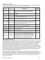
Advanced Stop Conditions ....................................................................................................................73
Advanced Stop Conditions Table ..........................................................................................................74
Advanced Stop Conditions Table ..........................................................................................................75
First Check ............................................................................................................................................75
Second Check .......................................................................................................................................75
Last Check .............................................................................................................................................75
Advanced Stop Parameters ...................................................................................................................76
Advanced Stop Conditions - QuickControl ............................................................................................77
Register Watch Tool ..................................................................................................................................78
Exercise 4.1 – Using the Register Watch Tool ......................................................................................78
SilverMax Register Based Motion Commands ..........................................................................................79
Register Moves ......................................................................................................................................79
Extended Register Moves .....................................................................................................................79
Profile Moves .........................................................................................................................................79
Registered Step and Direction (RSD) ....................................................................................................80
Input Modes ...........................................................................................................................................80
Exercise 4.2 – Simple Register Based Motion.......................................................................................80
Exercise 4.3 – Complete Register Based Motion ..................................................................................80
Program Flow Control ...............................................................................................................................81
Pausing Program Flow ..........................................................................................................................81
Jump Commands...................................................................................................................................82
Branching and Looping ..........................................................................................................................83
Other Program Flow Commands ...........................................................................................................84
Handshaking ..........................................................................................................................................84
Exercise 4.4 – Cut, Copy & Paste Programming ...................................................................................85
Chapter 5 – Advanced Motion Operations ................................................................................ 87
Register File System .................................................................................................................................87
Register Files .........................................................................................................................................87
Linking Text Files QuickControl Programs ............................................................................................88
Text File Format for Register File Import ...............................................................................................91
General Formatting ................................................................................................................................91
Register File Import Directives Formatting ............................................................................................91
Register File Details...............................................................................................................................92
SilverMax User Manual 4.0
v
Register File Details Alternative ............................................................................................................ 93
Register File Array Import Directives ..................................................................................................... 94
Register File Array Details ..................................................................................................................... 95
Techniques for Stopping Motion ............................................................................................................... 97
Software Stop Options........................................................................................................................... 97
Hardware Stop: Drive Enable feature ................................................................................................... 98
Profile Move Operation ............................................................................................................................. 98
Related Profile Move Commands .......................................................................................................... 99
Interpolated Motion Control ..................................................................................................................... 100
Registers Used with Interpolated Motion ............................................................................................. 100
Example of Interpolated Move: ............................................................................................................ 102
Interpolated Motion - Host Based Control ........................................................................................... 103
Chapter 6 – Input and Output Functions................................................................................. 105
Input and Output Operation..................................................................................................................... 105
SilverMax I/O Lines ............................................................................................................................. 105
SilverMax I/O Functions ...................................................................................................................... 106
Digital Inputs and Outputs ................................................................................................................... 106
Analog Inputs....................................................................................................................................... 107
High-Speed I/O Functions ................................................................................................................... 107
I/O Conflicts ......................................................................................................................................... 107
Using Digital Inputs ................................................................................................................................. 108
General Digital Inputs .......................................................................................................................... 108
Motion Control Inputs .......................................................................................................................... 109
Kill Motor on Input................................................................................................................................ 109
Modulo Trigger Input ........................................................................................................................... 109
Configure I/O (CIO) Command ............................................................................................................ 109
Digital Input Filter (DIF) Command ...................................................................................................... 109
Using Digital Outputs .............................................................................................................................. 109
General Digital Outputs ....................................................................................................................... 109
Configure I/O (CIO) Command ............................................................................................................ 110
Set Output Bit (SOB) Command .......................................................................................................... 110
Clear Output Bit (COB) Command ...................................................................................................... 110
Using Analog Inputs ................................................................................................................................ 110
SilverMax Analog Inputs ...................................................................................................................... 110
Using Analog Inputs for Program Flow and Data Monitoring .............................................................. 111
Analog Read Input (ARI) Command .................................................................................................... 111
Analog Read Continuous (ACR) Command ........................................................................................ 111
Input Mode Commands ........................................................................................................................... 112
Input Mode Operation .......................................................................................................................... 112
Velocity Input Mode ............................................................................................................................. 113
Position Input Mode ............................................................................................................................. 113
Torque Input Mode .............................................................................................................................. 113
Using Encoder Signals with Digital I/O .................................................................................................... 113
Encoder Signal Types ......................................................................................................................... 113
Step and Direction Signals .................................................................................................................. 114
Step Up/Step Down Signals ................................................................................................................ 114
A and B Quadrature Signals ................................................................................................................ 115
External Encoder Inputs .......................................................................................................................... 115
Direct Motion Control Inputs ................................................................................................................ 115
Dual Loop Control................................................................................................................................ 116
Encoder Outputs ..................................................................................................................................... 117
Raw Internal Encoder Output .............................................................................................................. 117
Scaled Internal Encoder Output (Modulo Output) ............................................................................... 118
SilverMax User Manual 4.0
vi
Chapter 7 – Torque Control ...................................................................................................... 119
SilverMax® Torque Overview ..................................................................................................................119
Torque Limit Operation............................................................................................................................119
SilverMax Units of Torque ...................................................................................................................120
SilverMax Torque Settings ..................................................................................................................120
Data Register Relationships ................................................................................................................121
Torque Control Methods..........................................................................................................................121
Chapter 8 – Shutdown and Recovery Techniques ................................................................. 127
Automatic SilverMax® Shutdown .............................................................................................................127
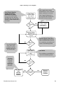
Servo Error Conditions (Kill Motor Conditions) ....................................................................................127
SilverMax Kill Process .............................................................................................................................129
SilverMax Shutdown Commands.........................................................................................................129
Other Relevant Commands .................................................................................................................130
Recovering or Restarting After a Kill Motor Condition .............................................................................130
Simple Shutdown Routine ...................................................................................................................130
Kill Motor Recovery from Uncontrolled Shutdown ...............................................................................131
Kill Motor Recovery from Controlled Shutdown ...................................................................................133
Power Loss Management and Recovery ................................................................................................134
Power Low Recovery Commands .......................................................................................................134
Other Related Commands ...................................................................................................................135
Recovering and Processing Saved Information...................................................................................135
Power Low Recovery and Restoration of Direction and Position ........................................................135
Time Needed For Saving to NV Memory .............................................................................................137
Backup Power Alternatives ..................................................................................................................137
Using the Kill Motor Process for Program Flow .......................................................................................138
Kill Motor Conditions as an Interrupt....................................................................................................139
Exercise 8.1 – Using an Input to Trigger a Kill Motor Shutdown .........................................................139
Exercise 8.2 – Simple Kill Motor Shutdown from Moving Error ...........................................................140
Chapter 9 – Serial Communication and Networking............................................................... 141
Selecting a Protocol and Interface ..........................................................................................................141
SilverMax Communications .....................................................................................................................142
Communication Port Settings ..............................................................................................................142
SilverMax Packets ...............................................................................................................................142
SilverMax Protocols.................................................................................................................................143
8-bit ASCII Communications................................................................................................................143
9-Bit Binary Communications ..............................................................................................................146
Serial Interface ........................................................................................................................................150
Comparing RS-485 and RS-232 ..........................................................................................................150
Choosing RS-232 or RS-485 ...............................................................................................................152
Implementing a SilverMax Communications Network .............................................................................152
General requirements ..........................................................................................................................152
Example Wiring Diagrams ...................................................................................................................153
Additional information and Troubleshooting ........................................................................................156
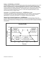
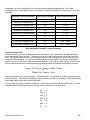
Chapter 10 - Tuning SilverMax® Servomotors ......................................................................... 157
Control System Overview ........................................................................................................................157
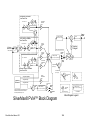
SilverMax PVIA™ Servo Algorithm......................................................................................................157
SilverMax Tuning Commands .................................................................................................................160
Primary Commands .............................................................................................................................160
Associated Commands ........................................................................................................................160
Overview of the Control System Parameters.......................................................................................161
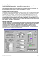
SilverMax Control Panel ......................................................................................................................170
SilverMax User Manual 4.0
vii
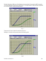
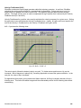
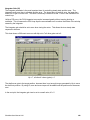
Example 10.1 - Tuning a 100:1 Inertial Mismatch ............................................................................... 171
Tuning Notes ....................................................................................................................................... 173
Appendix A - F........................................................................................................................... 175
Appendix A: SilverMax® E Series Specifications.................................................................................... 175
Electrical Specifications ....................................................................................................................... 175
Communication Specifications ............................................................................................................ 175
Servo Control Specifications ............................................................................................................... 176
Environmental Specifications .............................................................................................................. 176
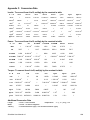
Appendix B: SilverMax® Data Registers................................................................................................. 177
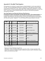
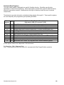
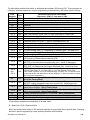
Appendix C: Conversion Data ................................................................................................................ 181
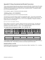
Appendix D: Binary, Hexadecimal and Decimal Conversions ................................................................ 183
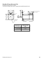
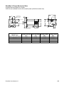
Appendix E: SilverMax® Mechanical Dimensions .................................................................................. 185
SilverMax 17 Frame Mechanical Data ................................................................................................. 185
SilverMax 23 Frame Mechanical Data ................................................................................................. 186
SilverMax 34 Frame Mechanical Data ................................................................................................. 187
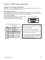
Appendix F: SilverMax® Connector Specifications ................................................................................. 189
SilverMax 17, 17H, 23 and 23H Connector Data ................................................................................ 189
SilverMax 34N & 34H Connector Data ................................................................................................ 190
SilverMax 34HC Connector Data ........................................................................................................ 191
Index .......................................................................................................................................... 193
SilverMax User Manual 4.0
viii
Chapter 1 - Using SilverMax® and QCI Start-up Kits
Introduction to Using SilverMax
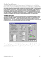
This section describes the common configurations for SilverMax systems (standalone, host, and hybrid). It
summarizes some of the ways multiple SilverMax motors can be used together, provides an overview of
SilverMax programming, and introduces QuickControl®: QCI‘s Windows based software interface for
SilverMax. Instructions for setting up the connections shown in each SilverMax configuration are given
later in this chapter. Each configuration drawing shows the connections for a 17 or 23 frame servomotor.
The connections for 34 frame servos used in similar configurations are slightly different and detailed later
(the addition of a voltage clamp module between the power supply and the servomotor is the most
important difference). Recommended setup (including parts list) is shown for each of the three common
configurations. A description of a generic setup is also given for each configuration.
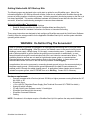
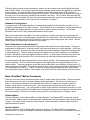
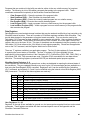
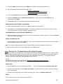
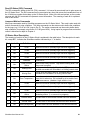
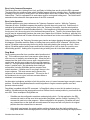
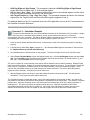
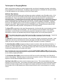
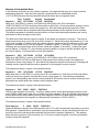
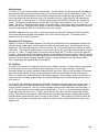
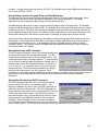
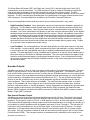
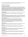
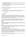
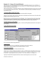
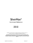
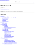
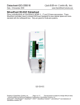
Standalone Configuration
SilverMax is capable of operating as a system-level controller without any input from a master controller or
user interface. When set up like this, SilverMax is pre-programmed to control the motion correctly and to
respond to any sensors or other inputs in the system.
System I/O
4
8
PC with
QuickControl
5
9
QCI
Breakout
2
SilverMax
6
Load
1
7
Power
Supply
3
Standalone Configuration
Recommended Setup
A typical standalone configuration is shown above. In this configuration, the SilverMax servomotor is
connected to a QCI breakout module, the breakout module is connected to any I/O devices, and the power
supply. The breakout module allows easy access to the serial, I/O, and power lines of the servomotor. A
PC running QuickControl is used to program and setup the SilverMax for standalone operation. After the
SilverMax standalone configuration is completed and operating correctly, the PC can be disconnected.
Recommend Parts List
1. SilverMax servomotor
2. QCI Breakout module
3. +12 to +48 VDC power supply
4. System inputs and/or outputs (not required)
5. PC running QuickControl
6.
7.
8.
9.
SilverMax cable
Power supply wires
I/O wires (not required)
DB9 serial cable
Generic Standalone Setup
SilverMax can be configured for standalone operation without a breakout module and without using QCI
cables. QCI recommends using QCI cables and a breakout module because of better reliability and ease
of installation. Likewise, using the QuickControl software is not a requirement since the servomotor will
respond to 8-bit ASCII strings or to 9-bit binary commands sent from any device capable of issuing them
SilverMax User Manual 4.01
1
over an RS-232 or RS-485 serial connection. However, QuickControl will usually allow faster prototyping
and is required to change the factory default initialization settings.
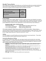
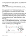
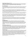
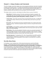
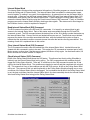
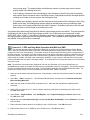
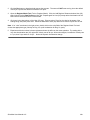
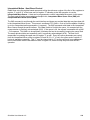
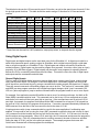
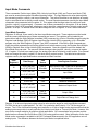
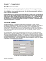
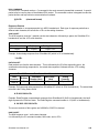
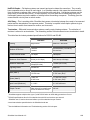
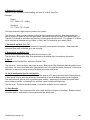
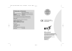
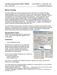
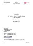
Host Configuration
Host configuration involves a SilverMax that is entirely controlled by a host PC, Programmable Logic
Controller (PLC), Human Machine Interface (HMI), or other such device. The host is connected to the
SilverMax through an RS-232 or RS-485 serial communication link. The host can issue a wide range of
commands to the SilverMax and can read SilverMax internal states like temperature and position.
Recommended Setup
A typical external host configuration using recommended parts is shown below. In this configuration, the
SilverMax servomotor is connected to a QCI breakout module and the breakout module is connected to the
external host and the SilverMax power supply. Any network connections or I/O points used in the system
are connected to the external host, not the SilverMax. The host controls all motion by issuing commands
to the SilverMax using the serial connection between them.
I/O
Network
Host
4
6
QCI
Breakout
2
5
SilverMax
1
Load
7
PC
Power
Supply
3
Host Configuration
Recommended Parts List
1. SilverMax servomotor
2. QCI breakout module
3. +12 to +48 VDC power supply
4. Host device (PC, PLC, HMI, Vision System, etc.)
5. SilverMax cable
6. Serial communications cable
7. Power supply wires
Generic Host Setup
As with a standalone configuration, SilverMax can be configured for host operation without using a
breakout module or QCI cables; the QCI equipment is recommended because it usually reduces
installation problems and makes troubleshooting easier. The most generic setup possible for SilverMax in
host mode is connecting the SilverMax to the external host and then connecting the host to power and to
any other system connections necessary (I/O points, network connections, etc.). This type of setup can be
simpler than the one recommended by QCI, but has the possible disadvantage of requiring a greater
understanding of SilverMax wiring requirements than a setup using QCI parts.
SilverMax User Manual 4.01
2
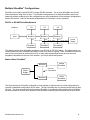
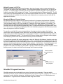
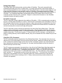
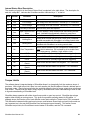
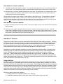
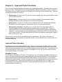
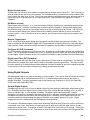
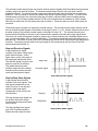
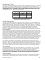
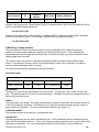
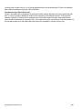
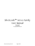
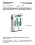
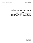
Hybrid Configuration
A hybrid configuration utilizes a SilverMax operating such that is directed by an external controller,
executing internal programs, and using its internal I/O points. This configuration is more versatile than
either a pure standalone or pure host-controlled configuration. SilverMax can use its standalone abilities to
execute internal programs and interact with the system through its I/O points, also an external host can
issue commands or interact with SilverMax programs. For example, a PLC could direct the SilverMax to
switch tasks or stop motion in response to a digital input from the PLC,
Recommended Setup
A typical hybrid configuration using recommended parts is shown below. In this configuration, SilverMax is
connected to a QCI breakout module; the breakout module is then connected to the power supply, any I/O
devices needed to interface to the SilverMax, and the host device. The host can also be connected to I/O
devices, a network, or anything else it is capable of interfacing with. Note that the host can also interface
with the SilverMax when some of the SilverMax I/O lines are connected to the host.
System I/O
5
I/O
7
Network
Host
4
9
QCI
Breakout
2
SilverMax
6
1
Load
8
PC
Power
Supply
Hybrid Configuration
3
Recommended Parts List
1. SilverMax servomotor
2. QCI breakout module
3. 12 – 48 VDC power supply
4. Host device (PC, PLC, HMI, Vision System, etc.)
5. SilverMax inputs and/or outputs (application specific)
6. SilverMax cable
7. I/O wires (application specific)
8. Power supply wires
9. Serial communications cable
Generic Hybrid Setup
The QCI-recommended configuration is often easier for new users and more reliable for experienced
users, but systems using custom-built cables or slightly different configurations can work just as well. A
generic hybrid configuration would be a combination of the generic standalone and host configurations,
with custom cables providing connections between the host and the SilverMax, the SilverMax and a power
supply, and the SilverMax and any I/O devices the system required.
SilverMax User Manual 4.01
3
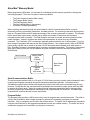
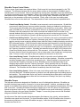
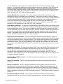
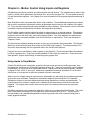
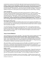
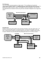
Multiple SilverMax® Configurations
SilverMax can be part of small RS-232 or larger RS-485 networks. Two or more SilverMax can also be
interconnected by using their I/O lines. The possible configurations for multiple SilverMax systems are
seemingly endless, although all of the configurations are just combinations of the two basic configurations
listed in this section. Many of the advanced applications for SilverMax use this capability.
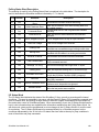
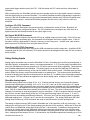
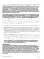
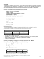
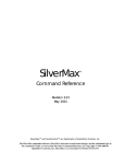
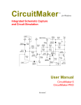
RS-232 or RS-485 SilverMax Network
Network
I/O
I/O
I/O
Host
Breakout
Breakout
Breakout
Power
Supply
SilverMax
SilverMax
SilverMax
This drawing shows three SilverMax configured on an RS-232 or RS-485 network. The external host can
communicate with each SilverMax individually or with all of them as a group. Each SilverMax can have its
own I/O lines connected to external devices (or to each other as described below) and can execute
programs independent of the rest of the network—just like a hybrid configuration.
Master-Slave SilverMax®
Master
SilverMax
Breakout
I/O Line
Connection
Power
Supply
Breakout
Slave
SilverMax
This figure shows two SilverMax configured to work together in what amounts to a host configuration for
one and a standalone configuration for the other. The two SilverMax are only interconnected through their
I/O lines. This interconnection allows the master SilverMax to coordinate motion with the slave SilverMax.
Advanced details on master-slave operation and SilverMax networking are described later in the manual.
SilverMax User Manual 4.01
4
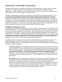
QuickControl® and SilverMax® Programming
SilverMax has an extensive command set that allows it to be programmed for a wide variety of complex
applications. SilverMax needs to be pre-programmed if it is to be used in a standalone or hybrid
configuration. In host configuration, the host issues commands directly to the servo for execution and no
user program is stored in the SilverMax non-volatile memory.
SilverMax is programmed from a series of commands issued through a serial communications link. The
most practical way to program SilverMax is to issue these commands from the QuickControl software
running on a PC. QuickControl is QCI‘s Windows-based software interface for SilverMax. It can run on
Windows 9x, NT, ME, 2000, or XP based PC connected to a SilverMax servomotor using one of the PC‘s
serial ports. QuickControl is designed to make programming SilverMax easy and efficient. Programming
SilverMax and using its advanced features is the topic of most of this manual, and QuickControl is used in
nearly all of the examples. It is also the only SilverMax programming interface fully supported by QCI and
is always required to change the SilverMax factory default initialization program.
SilverMax Programming Overview
The SilverMax command set is accessible by any device capable of communicating over an RS-232 or RS485 serial connection. This means that almost all host controllers (HMI, PLC, Vision, and PC systems) can
be used to communicate with and control SilverMax. Many applications require commands to be sent from
the host directly to SilverMax. This type of control is usually prototyped and tested more efficiently using
QuickControl. For example, an application might require a custom program written in C++ running on a PC
to dynamically issue a series of commands to a SilverMax connected to the PC. SilverMax operation could
be setup for this application without the use of QuickControl, but the development and prototyping of the
application is easier, faster, and more accurate if done with QuickControl.
SilverMax programs are made up of two components: the initialization program and user programs. The
initialization program contains all the initialization settings as well as default settings for some of the
advanced SilverMax functions. User programs contain the instructions SilverMax follows while operating in
standalone or hybrid configuration.
•
Initialization program. The initialization program starts at the first memory location in non-volatile
memory (address 0). After a SilverMax powers up, it automatically executes the program that starts
at the first memory location. This program must contain initialization instructions for the SilverMax
or it will not operate properly. Every SilverMax comes from the factory with a default initialization in
the proper memory location. QuickControl has several tools for safely changing the default
initialization. The last command in the default initialization program is a command to load and run
the program that starts at memory address 512. This is the default location for the start of the first
user program.
•
User programs. User programs give SilverMax much of its true power and allow it to act as a truly
intelligent servomotor. User programs are integral to the standalone and hybrid configurations,
since in those configurations, the logic and control load is entirely or partially shifted to the
SilverMax. User programs are formed by linking commands together. The SilverMax command set
includes commands for program flow, logic and math functions, memory manipulation, as well as
numerous commands to control the motion of the SilverMax. QuickControl includes tools to aid in
creating programs, as well as an on-line description of each command.
SilverMax User Manual 4.01
5
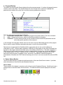
Features of QuickControl®
QuickControl contains a wide array of tools and features designed to make using and programming
SilverMax easier. These tools are all available through the QuickControl interface, although learning how
to access them and what each one is used for can take some practice. A full listing of all of QuickControl‘s
features is too long to list here, but some of QuickControl‘s tools and features are summarized below.
Getting started with QuickControl is covered later in this chapter and many of its features are illustrated
throughout this manual. QuickControl also has an extensive on-line help library.
•
Communications. QuickControl includes several tools to make establishing and monitoring
communications between the PC and SilverMax easier. These tools monitor the status of
SilverMax connected to the PC.
•
Initialization. QuickControl must be used if the factory default initialization program needs to be
changed. SilverMax can be run in a host configuration with no internal user programs running, but
the initialization program always runs when SilverMax first powers up.
•
Programming. QuickControl is designed to make writing new SilverMax programs as easy as
possible. Every command added to a program using QuickControl is done so with a dialog box that
prompts the programmer for each required parameter, thus reducing the chance of invalid data
errors. Each command dialog box also includes a description of the command for easy reference.
•
Troubleshooting. The most painstaking part of almost any development project is troubleshooting
the prototype. QuickControl not only has many of the common tools for debugging such as trace
and single-line execution, but also includes several tools that allow access to registers and to the
command and data packets that are actually transmitted and received by the SilverMax.
•
Tuning. SilverMax can be tuned for very high inertial mismatches and for systems with difficult
plants (such as systems that include a highly elastic element like a belt). QuickControl includes
tools designed to make the tuning process as efficient and effective as possible, including a built-in
strip chart tool that can track position, velocity, torque, and error.
•
Housekeeping. QuickControl includes several tools to manage simple tasks like saving and
loading programs and cutting and pasting commands between and within programs, as well as
more advanced tools like a program upload (retrieving a program from a SilverMax) tool and a
firmware upgrade wizard.
SilverMax User Manual 4.01
6
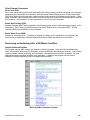
Getting Started with QCI Start-up Kits
The following pages are designed to be a quick start up guide for new SilverMax users. Most of the
information applies to QCI Start-up Kits and will take a user who is unfamiliar with SilverMax through the
process of putting together a functioning system. Achieving a perfectly functioning system on the first try is
not always applicable. This section addresses hardware and software issues that some first time users
encounter, as well as troubleshooting strategies to overcome these obstacles.
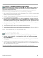
Before Using SilverMax® Servomotors
• Turn Off ALL Power Supplies and Switches
• Read All Setup Instructions for Specific SilverMax Model and Start-Up Kit
• Double-check ALL Intended Connections for Shorts or Unwanted Grounding
These setup instructions are designed to help configure a SilverMax servo and the QuickControl Software.
Carefully follow the setup procedure for the applicable SilverMax Start-Up Kit, and the system should be
operating within minutes.
WARNING: Do Not Hot Plug The Servomotor!
When a SilverMax is powered, and plugged in or unplugged anywhere along the 15-pin signal cable,
this is defined as Hot Plugging. When this occurs, the residual current in the power circuitry (motor
windings, power supply, voltage clamp, 5 Volt supply, communication power…) attempts to find the
path of least resistance to ground (before the proper ground connection is established). In most
cases this path is through the communication lines (but is not limited to communication failure). The
available protection devices are not rated for high transient power spikes, or repeated spikes.
Repeated spikes can weaken communication slowly to the point of failure. In some cases, total
communication failure can occur in the first and only instance of Hot Plugging.
In applications, this can be overcome by connecting chassis ground (a lug on the servomotor body) to
the power supply ground. With this direct ground implemented, the path of least resistance for
residual power is through the added chassis ground. In applications where chassis ground must be
isolated from power ground, take EXTREME care not to Hot Plug. Contact QCI if necessary.
Hardware requirements
•
•
•
•
•
•
•
•
Personal computer with a Pentium (at least 133 MHz) or higher processor running Windows 9x, NT,
Me, 2000, or XP.
SilverMax Servo
+12 to +48 VDC Regulated Power Supply (See Technical Document QCI-TD002 for details.)
Startup Kit which includes:
CD with QuickControl Software version 3.2 and higher
SilverMax User Manual (this document)
SilverMax Command Reference
Cabling
NOTE: Procedures in this chapter require a SilverMax Start-Up Kit to perform the setup and initialization.
SilverMax User Manual 4.01
7
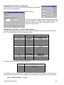
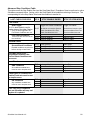
SilverMax® Factory Defaults:
When shipped from the factory, the SilverMax servo and QuickControl software are configured with default
values that are used to establish initial communications between SilverMax and a PC. These default
values can be changed to different settings during the initialization procedure.
SilverMax Unit ID (address)
SilverMax Supply Voltage
Serial Communications Protocol
Serial Interface
Baud Rate
16
48VDC
8 Bit ASCII
RS-232
57600
Power Supplies
SilverMax operates from a supply voltage of +12 VDC to +48 VDC and has to be initialized for the specific
operating voltage ( 10% output tolerance). The power supply can be a switching or linear type, but should
be chosen so that the power output meets or exceeds the power requirement of the SilverMax. Check the
product datasheets for maximum current specifications on the QCI web site http://www.SilverMax.us.
MINIMUM POWER SUPPLY SPECIFICATIONS
REGULATED SUPPLY
OVER CURRENT FOLD-BACK PROTECTION
± 10 % OUTPUT TOLERANCE
SHORT CIRCUIT PROTECTION
± 2.0 % LOAD REGULATION
OVER VOLTAGE PROTECTION
QCI strongly recommends voltage-clamping protection on all DC power supplies. Voltage clamping
controls the back EMF generated by electric motors during the deceleration of large inertial loads. External
power supply clamp modules are available from all authorized QCI Distributors. For more information on
the QCI voltage clamp modules see Technical Documents QCI-TD006.
Cabling
QCI offers cabling for use with SilverMax and accessory products for general applications. These cables
have documentation describing physical dimensions and pin outs.
Custom/User Manufactured Cabling
If an application requires custom cabling, the correct pinout must be used to develop the correct wiring
harness. SilverMax 17, 23, and 34 frame sizes have different cabling specifications that must be followed.
The following are some design requirements that are incorporated into standard QCI cables but could be
easily overlooked when manufacturing custom cabling.
• Shielding—I/O and communication lines are susceptible to noise in many industrial environments.
• Grounding—SilverMax has logic, processor, power, and chassis grounds that must be wired
correctly.
• Null modem connections—the transmit line on SilverMax is connected to the receive line on a
serial port and vise versa for the receive line on SilverMax (RS-232).
• Sound electrical junctions—it may be beneficial to use crimp style connectors rather then the
solder tail type to avoid unintentional solder bridging across adjacent pins. Lines with poor
electrical junctions could cause intermittent contacts that could effectively Hot Plug SilverMax and
disable communications.
• Wire gage—ensure lines meet the specified current requirements.
SilverMax User Manual 4.01
8
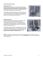
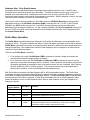
QCI Start-Up Kits Overview
QCI-SK Start-Up Kit
(SilverMax, personal computer, and power supply not included)
provide a simple and inexpensive means for testing and evaluating a
SilverMax servomotor. With a standard PC serial COM port and a
power supply, any SilverMax servo can be fully programmed and
operated with the RS-232 communication protocol.
The SilverMax Training Breakout Module is included in each kit to
connect a SilverMax to a PC, a power supply, and to breakout I/O.
Also included are the QuickControl Software, the SilverMax User
Manual, and the SilverMax Command Reference.
QCI-SKO Start-Up Kit
(SilverMax, personal computer, and power supply not included)
provide a means for testing and evaluating a SilverMax
servomotor through an Optical I/O board. With a standard PC
serial COM port and a power supply, any SilverMax can be fully
programmed and operated through an Optical I/O board with the
RS-232 communication protocol.
The SilverMax Interface cable is included in each kit to connect a
SilverMax to the Optical I/O board. An additional cable is provided
for the connection of the I/O board and a personal computer. Also
included are the QuickControl Software, the SilverMax User
Manual, and the SilverMax Command Reference.
NOTE: 34 frame Start-Up Kits include a Line Power cable (not shown), which is required in 34 frame
SilverMax applications to power the servomotor. This cable DOES NOT need to be purchased separately
from the Start-Up Kit.
SilverMax User Manual 4.01
9
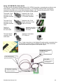
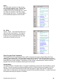
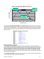
Setup: QCI-SK-fs Start-up Kit
The Training Breakout Module (QCI-BO-T) is the focus of this start-up kit for prototyping and evaluating 17
and 23 frame SilverMax servos. Technical document QCI-TD016 contains details on its operation and
specifications. Below is a picture of the Training Breakout Module with important areas numbered and
labeled:
2 - Power Switch
4 – 9-Pin Female Receptacle
5 – 9-Pin Male Receptacle
Terminal labeled ―VIN‖
3 - 15-Pin Female Receptacle
Terminal labeled ―PGND‖
The female end of the
SilverMax Interface
Cable
attaches to the 15-pin
male connector on
SilverMax.
The male end of the
SilverMax Interface
Cable
attaches to the 15-pin
female receptacle (3)
on the Training Breakout.
The female end of
the Communications
Cable
attaches to a standard
9-pin PC COM port.
The male end of the
Communications
Cable
attaches to the 9-pin
female receptacle (4)
on the Training Breakout.
1 - Main Terminal Block
Apply a connection for input voltage (+12 to +48 VDC) to the terminal labeled ―Vin‖ on the Main Terminal
Block (1) of the Training Breakout Module and apply a connection for input (supply) ground to the terminal
labeled ―PGND‖.
SilverMax User Manual 4.01
10
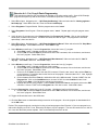
Setup: QCI-SK-fc Start-Up Kit
The setup for this kit is the same as the setup described above for the QCI-SK-34 Start-Up Kit, except a
Clamp Module (QCI-CLCF-04) and Resistor Pack (QCI-CLRP-2) are included. This kit is to be used with
34 frame SilverMax servomotors.
The female end of the
SilverMax Interface
Cable
attaches to the 15-pin
male connector on the
SilverMax 34N/H servo.
The SilverMax Line
Power Cable
attaches to the
3-pin receptacle
on the SilverMax
34N/H servo.
The red wire at the end of the SilverMax Line Power Cable is connected to Vout (3) terminal on the Voltage
Clamp. The black wire connects to the Gnd (4) terminal on the Voltage Clamp. The white wire connects to
chassis ground of the power supply. DO NOT make any other connections to the outputs on the Voltage
Clamp other than to the 3-pin receptacle on SilverMax. In the case of SilverMax regenerating, any added
circuitry connected to Voltage Clamp outputs is not protected and could be damaged by the back EMF.
Connect the Vin (1 & 5)
terminals to the V+ of the
power supply and connect
Gnd (2 & 6) terminals to the
ground of the same supply.
The male end of the
SilverMax Interface
Cable
attaches
female
on the
Wire the resistors of QCI-CLRP-2 as
needed (see QCI Technical
Document QCI-TD0017) to obtain
appropriate clamping resistance and
connect leads to the Res 1 and Res 2
terminals on the Voltage Clamp.
to the 15-pin
receptacle (3)
Training Breakout.
The female end of
the Communications
Cable
attaches to a standard
9-pin PC COM port.
The male end of the
Communications
Cable
attaches to the 9-pin
female receptacle (4)
on the Training Breakout.
Apply a connection for input voltage (+12 to +48 VDC) to the terminal labeled ―Vin‖ on the Main Terminal
Block (1) of the Training Breakout Module and apply a connection for input (supply) ground to the terminal
labeled ―PGND‖.
SilverMax User Manual 4.01
11
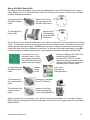
Setup: QCI-SKOM-FS-v Start-Up Kit
This Start-Up Kit with Optical Interface Module (QCI-OPTM-V) provides a comprehensive solution to test
and evaluate 17 and 23 frame SilverMax servomotors. The SilverMax interface cable is provided to
connect the SilverMax servo to the Optical Interface Module. QCI Technical Document QCI-TD0013
(included) contains more information on the Optical Interface Module.
The female 15-pin
connector on the
SilverMax Interface
Cable
attaches to the 15-pin
male connector on the
17/23 frame SilverMax.
The male 15-pin
connector on the
SilverMax Interface
Cable
attaches to the 15-pin
female connector on the
Optical I/O board.
The RJ-11
connector on
the serial cable
The 9-pin female
connector of the
serial cable
attaches to the RJ-11
jack on the Optical
I/O board.
attaches to a standard
PC COM port.
The +V Input connections on the Optical I/O board must be connected to the
V+ terminal of a power supply (10-48VDC) and the Pwr Gnd connections
must be connected to the ground of that power supply.
SilverMax D15: Connect to
SilverMax and tighten
thumbscrews
15-pin Interface Cable:
Connect to Optical I/O Module.
RJ-11 Cable:
Connects to RJ-11 port
on Optical I/O Module
to PC COM port.
Power Supply Connectors:
+V Input to V+ of power supply
and Pwr Gnd to Ground.
SilverMax User Manual 4.01
12
Setup: QCI-SKOM-FC-v Start-Up Kit
The setup for this kit is the same as the setup described above for the QCI-SKOM-34-V Start-Up Kit,
except a Clamp Module (QCI-CLCF-04) and Resistor Pack (QCI-CLRP-2) are included. QCI Technical
Document QCI-TD0013 (included) contains more information on the Optical Interface Module.
The female end of the
SilverMax Interface
Cable
attaches to the 15-pin
male connector on the
SilverMax 34 servo.
The SilverMax Line
Power Cable
attaches to the
3-pin receptacle
on SilverMax.
The male 15-pin
connector on the
SilverMax Interface
Cable
attaches to the 15-pin
female connector on the
Optical I/O board.
The RJ-11
connector on the
serial cable
attaches to the RJ-11
jack on the Optical
I/O board.
The 9-pin female
connector on the
serial cable
attaches to a standard
PC COM port.
The red wire at the end of the SilverMax Line Power Cable is connected to the Vout (3) terminal on the
Voltage Clamp. The black wire connects to the Gnd (4) terminal on the Voltage Clamp. The white wire
connects to chassis ground of the power supply. DO NOT make any other connections to the outputs on
the Voltage Clamp other than to the 3-pin receptacle on the SilverMax. In the case of SilverMax
regenerating, any added circuitry connected to Voltage Clamp outputs is not protected and could be
damaged by the back EMF.
Connect the Vin (1 & 5)
terminals to the V+ of the
power supply and connect
Gnd (2 & 6) terminals to the
ground of the same supply.
Wire the resistors of QCI-CLRP-2 as
needed (see QCI Technical
Document QCI-TD0017) to obtain
appropriate clamping resistance and
connect leads to the Res 1 and Res 2
terminals on the Voltage Clamp.
The +V Input connections on the Optical I/O board must be connected to
V+ of a power supply and Pwr Gnd connections must be connected to
Ground of that power supply. The V+ Fused connection must be tied to the
ENA /V+ connection to enable the Drive Enable line on SilverMax. This
connection can be made with the included jumper or external switching
circuitry.
SilverMax User Manual 4.01
13
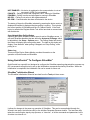
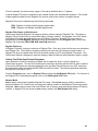
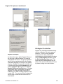
Software Requirements
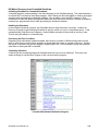
Installing QuickControl® Software:
Note: Do not power up the SilverMax until the setup procedure specifies this action.
Note: QuickControl can control SilverMax in ―real-time‖; it therefore needs full access to PC resources.
When installing QuickControl, it is necessary to close all shared files and exit open applications. It is also
highly recommended that applications requiring large system demands be closed and any screen saver is
disabled. Background tasks can cause interference and should be reduced to minimum requirements.
1) Insert the QuickControl Setup CD into the CD ROM drive. If QuickControl setup automatically
runs, follow the instructions and go to step 5; else go to step 3.
2) From the Start menu select
Start > Run
3) Type in the setup program:
[CD Drive Letter]: \setup
Follow the instructions on the screen. It is strongly recommended that ―Typical‖ installation
is selected and all the defaults are accepted.
4) Reboot PC: Remove any diskettes and re-boot the PC. This can be done by selecting:
Start > Shut Down – Restart the Computer?
5) Run QuickControl: From the Start menu select,
Start > Programs > QuickControl
QuickControl will come up with a blank program.
6) Initialize and Program SilverMax
Go to the QuickControl Help System for a detailed step-by-step procedure on:
Initializing SilverMax
Programming SilverMax
The QuickControl Help system is accessed through:
Help > Help Topics > Getting Started – Tutorials
SilverMax User Manual 4.01
14
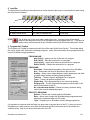
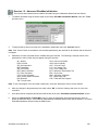
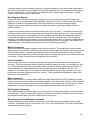
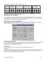
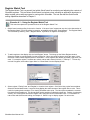
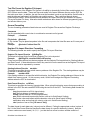
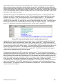
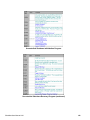
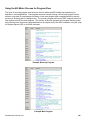
Find SilverMax on the COM port
With the SilverMax powered up, start QuickControl and the polling routine should automatically find
SilverMax. If QuickControl is already running and the SilverMax is powered up, press the ―Scan Network‖
button to find SilverMax on the network. If ―Device Not Found‖ appears in the Device Status Monitor, either
the SilverMax has been configured with something other than the Factory Defaults (listed in the Hardware
Requirements section of this chapter) or QuickControl is not set up to communicate with the SilverMax in
its present communications state. Some things to check if this happens are:
•
•
•
•
•
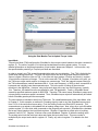
Under Setup, select Comm Port / Comm Channels and ensure the baud rate and protocol are set
to Factory Defaults (57600 and 8 bit ASCII respectively). Also, confirm the Enable checkbox is
checked and the COM Channel enabled is the one SilverMax is connected to.
Under Setup, select Register Devices and ensure all six devices have the Auto Reg checkbox
checked.
If networking multiple SilverMax, QuickControl can register six at a time for viewing.
If networking multiple SilverMax, each has to be initialized with the SilverMax Initialization Wizard
with a unique ID.
Under Setup, select Options and make sure the Autoscan ID range encompasses the ID of the
SilverMax units desired.
Troubleshooting SilverMax® Communication
There are two indicator light emitting diodes (LED) on the back of every SilverMax servo, one red and one
green. These LED indicators provide the user some basic information about the current operational state
of the SilverMax. When SilverMax is powered up the green and red LEDs should both be on. The red LED
is the SilverMax communication indicator.
If the red LED is on solid (dim glow), then no program is running in the SilverMax is not communicating.
When SilverMax receives the start of a transmission, the red LED will shine extra bright. When the
transmission is processed, the red LED will return to its original state. Sending SilverMax a number of
commands in succession (e.g. the QuickControl polling routine) will induce a flickering of the red LED. This
flickering can occur in regular intervals or as random blinks depending on the communication scheme.
If the red LED is out completely, then a program is running from the internal nonvolatile memory.
Communications Troubles
Know the PC hardware and what port is physically connecting to the SilverMax. In QuickControl, verify the
Communication Port is enabled and is the actual port being used to connect to SilverMax. Verify there are
no other programs using the port (only one program can control a COM Port at any given time). These can
include other motion control drivers or programs used for communication devices (e.g. Palm Pilot,
HyperTerminal etc.). If these programs do not relinquish control of the port, QuickControl will report ―Could
Not Open select COM Port‖ and ―Access is denied.‖ errors in the Status Log.
After verifying the integrity of the COM Port and making any necessary changes, try a quick communication
test. Stop the QuickControl polling routine (if it is running), and click on the red hand icon button on the QC
toolbar. The red LED on the back of SilverMax should flash briefly as it receives and processes the Halt
command sent to it. This simple test can be done at any time to verify that SilverMax is receiving
commands.
If the SilverMax is in an unknown communication state, there is no way to explicitly configure QuickControl
to establish communications. The Unknown SilverMax Wizard, located under the Tools menu, is
designed to overcome this obstacle. Before the initialization file executes, when SilverMax is first powered
up, it automatically comes up configured for 57600 Baud and toggles momentarily between 8-Bit ASCII and
9-Bit Binary communications. The Unknown SilverMax Wizard sends out a continuous stream of Stop
commands through the COM port stopping execution of the initialization file, and preventing SilverMax from
reaching an unknown communications state. The wizard will then prompt for communication configuration
of SilverMax. These settings should match how QuickControl is configured. Note that the protocol (8-bit
SilverMax User Manual 4.01
15
ASCII or 9-bit Binary) is determined by the settings under Comm Port in the Setup menu of QuickControl
to ensure that the protocol matches QuickControl. Upon completion of the wizard, the SilverMax will be
successfully communicating. See ―SilverMax Power Up Sequence‖ later in this chapter for a detailed
explanation of how this is achieved and how to manually implement this routine in a host system.
It is also good to verify that the Windows PC can communicate through the serial port without
QuickControl. Programs like HyperTerminal can accomplish this. Follow the QCI application note,
QCI013AN - PLC emulation with HyperTerminal, for the correct setup. If communication is successful with
the third party terminal program, then QuickControl should be able to operate correctly.
QuickControl® Interface
The main QuickControl screen offers the user an easy to use programming interface with the ability to
monitor the communications status of all active SilverMax units connected to the PC Host. An active status
log is available for viewing the status information the active SilverMax are sending to the host. In addition,
any device connected to the host can be selected in order to view current position and the active I/O states.
The Main QuickControl Screen is divided into five major sections.
1)
2)
3)
4)
5)
The Menu Bar contains pull down menus with all the functions of QuickControl.
The Icon Bar contains the most often-used menu items as shortcuts.
The Program Info Toolbar displays programming and program information.
The Program Window displays the active program.
The Device Status Monitor provides information about all connected SilverMax.
1
2
3
4
5
S23H-5
SilverMax User Manual 4.01
16
1. Menu Bar
The QuickControl Menu Bar provides access to all functions of the software. These ―pull down‖ type
menus offer many selections that can bring up other menus to accomplish certain objectives. Above the
Menu Bar, next to the QCI logo & QuickControl name is the active filename being displayed in the
QuickControl Program Window.
File Menu
New Program File - Opens blank program template
New Sequence File – Opens blank sequence template
Open – Opens a saved file
Close – Closes the active file in QuickControl
Save – Saves the current file
Save As – Saves the current file with user set parameters
Program File Properties – Contains scaling, password protection, and user defined names
Upload Program File – Retrieves the current program residing in Non Volatile memory
Print – Prints the active QuickControl Program file to the default printer
Print Setup – Allows the user to change printer and paper settings
All Halt – Sends the All Halt command
Recent Files – Displays a list of files recently open in QuickControl
Exit – Closes the current files opened and exits QuickControl
Edit Menu
Cut – Removes highlighted section of text or program line
Copy – Copies highlighted section of text or program line
Paste – Inserts a copied or cut section of text or program line before selected line
Select All – Highlights an entire program
Events – Events Menu
(Events are used to create CTL files)
Event lists (CTL files) are command lists that are sent by a host to SilverMax via the serial
interface. They are not downloaded to SilverMax and executed from the command buffer
like a program (QCP) file.
Create Event – Creates a new event
Edit Event – Edits an existing event
Lite Edit Event – Temporary modification of an event for execution
Copy Event – Copies a selected event
Delete Event – Deletes a selected event
Execute Event – Executes a selected event
Define Event Template – Creates and defines a new event template
Edit Event Template – Edits a selected event template
Copy Event Template – Copies a selected event template
Delete Event Template – Deletes a selected event template
Edit Data Template – Edits a selected data template
Define Data Template – Creates and defines a new data template
Copy Data Template – Copies a selected data template
Delete Data Template – Deletes a selected data template
Save Events Database – Saves the selected event template
View Menu
Toolbar – When checked, Toolbar will be displayed
Status Bar – When checked, Status Bar will be displayed
Device Status – When checked, Device Status will be displayed
SilverMax User Manual 4.01
17
Program Menu
Add Line – Adds a new line to a program
Insert Line – Inserts a line above the selected line in a program
Edit Line – Edits the selected line in a program
Delete Line – Deletes the selected line in a program
New Program – Creates a new blank program
Delete Program – Deletes selected program
Program Details – Allows a user to name, describe, and modify the stored location of a program
Scaling – Allows a user to adjust scaling parameters and max/min ranges
Register Files – Links register files or file arrays (.txt based) to active QuickControl program
Register Names – Assigns user defined names to registers
I/O Names – Assigns user defined names to I/O lines
Run Program w/o Save – Runs current program without storing the program to NVM
Erase Application in Device – Erases current program in non-volatile memory
Toggle Breakpoints – Toggles Breakpoint at current line
Clear all Breakpoints – Clears all Breakpoints in all programs
Tools Menu
SilverMax Initialization Wizard – Sets up and initializes SilverMax servos
Unknown SilverMax Wizard – Establishes communications with a SilverMax unknown parameters
SilverMax Control Panel – Tool for Jogging, Tuning, and Monitoring SilverMax
Register Watch – Change and/or view data in the SilverMax data registers with this utility
Data Monitor – Monitor all data sent and received by SilverMax and the PC
Rev 3.1 Tools – Rev 3.1 Tools Menu (Tools available in previous QuickControl versions)
Use only with Legacy Series of SilverMax. DO NOT use any of these utilities as an
alternative to existing utilities for any E Series SilverMax.
Jog SilverMax – Jog utility within 3.1
Initialize SilverMax – Initialization utility within 3.1 for initialization sequence files
Motion Tuning – Tuning utility within 3.1
Unknown SilverMax Wizard – Establishes communication with Legacy SilverMax
SilverMax Firmware Download Wizard – Downloads firmware to SilverMax
Setup Menu
Comm Port – Selects Baud Rate, COM port, and Protocol for QuickControl
Simulator – Allows user to setup computer as a SilverMax simulator with ID and com
Register Devices – Allows user to manually registers devices into QuickControl
Options – Allows user to edit other setup specifications
Polling – When checked, starts QuickControl polling the network for any connected SilverMax and
then displays the state of the device in the Device Status window
Verbose – When checked, enables extra error messages and warnings
Window Menu
New Window – Creates a new program window
Cascade – Cascades current program windows
Tile – Displays current program windows in a tile arrangement
Arrange Icons – Arranges and aligns minimized program icons
Current Program List – A list of programs currently open in QuickControl
Help Menu
Help Topics – Opens help menu for tutorials and information on QuickControl
About QuickControl – Displays date and version of QuickControl and product support information
SilverMax User Manual 4.01
18
2. Icon Bar
The QuickControl Icon Bar provides shortcuts to certain functions that may be used repetitively while using
the QuickControl software.
1
1
4
7
10
2
3
4
Create a New Program
Save the Active Program
Copy Selection in Program
About QuickControl
STOP
5
2
5
8
11
6
7
8
9
Open an Existing File
SilverMax Initialization Wizard
Paste Selection in Program
Help on Selected Item
3
6
9
12
10
11
12
Close the Active Program
Cut Selection From Program
Print Active Program
All Stop
The All Stop Icon is the most widely used of the icons. It serves to stop all command
execution and programs running in all SilverMax servos connected to the PC. It can also be
used to verify communications to any SilverMax as the Red LED blinks briefly when issued.
3. Program Info Toolbar
The Program Info Toolbar is located on the left side of the main QuickControl Screen. This toolbar allows
the user to create, edit, download, and debug programs. It also offers information about programs and the
current SilverMax being programmed.
PROGRAM LINE
Add (Ctrl-A) – Adds a new line to the end of a program
Edit (Ctrl-E) – Edits the selected line in a program
Insert (Ctrl-I) – Inserts a line above a selected line in a program
Delete (Ctrl-D) – Deletes the selected line in a program
PROGRAMS
Download – Downloads all programs in the active file to SilverMax
Run – Downloads and Runs all programs in the active file
Scaling – Allows user to adjust program scaling parameters and other
program related settings including upload password.
Test Line – Tests the specific highlighted line of program
Trace – Traces a program through all lines
Single Step – Runs a program line by line via user prompting
Program List – The list of selectable programs currently open in the
active QuickControl file (QCP)
No. of words used window – Shows how many words are being
used in the currently displayed program
S23H-5
DEVICE TO PROGRAM
Reboot – Reboots the currently selected SilverMax
Desc – Allows user to select the SilverMax being programmed and
displays the registered label and ID number
Type – Displays type of SilverMax currently being programmed
It is important to note that while the Save icon does save to the hard drive of the PC, it does not save to
SilverMax non-volatile memory; and, while the Download and Run buttons do save to SilverMax non
volatile memory, they do not save to the hard drive of the PC.
SilverMax User Manual 4.01
19
4. Program Window
This area of the QuickControl Screen displays the active program opened. It is where all program lines are
created, viewed, and edited. The interface allows the user to single click on the line to highlight that
particular line or double click on the line to edit the contents (parameters) of that line.
2
1
3
There are three columns in the Program Window.
1)
Line Number and Operation – Displays the program line number and the TLA of the command.
2)
Label – Allows the user to put in labels for branching operations in programs.
3)
Command – Provides a brief summary of the command on that line and the parameters that are
set in that specific operation of the command.
In this example of the Program Window, there are two colors used to differentiate the lines of the program.
Blue is used for actual SilverMax commands and green is used for the remarks (REM).
Remarks are not downloaded to SilverMax with the commands and are only used for adding text
information to a QCP. When a label is placed on a REM line in the program, the line that is activated from
that label in the program when downloaded is the next available command line. If the label is placed on a
REM line that is at the end of a program it will be the next available command line up from that REM line.
In the example above, ―START‖ is a label on line 1, a REM line. The program branches to the START
label from Line 4 when the I/O condition is met. Since line 1 is a REM line, when this program is
downloaded to SilverMax the START label will actually point to line 2, the next command line after the REM
line.
5. Device Status Monitor
The Device Status Monitor occupies the right hand portion of the main QuickControl window. It provides
status information on QuickControl and the attached devices.
Device Status
The top portion of the display is used as a quick reference to the Registered Devices. QuickControl uses a
polling routine to check the status of these devices. Five different buttons can be displayed in the status
area.
1
SilverMax User Manual 4.01
2
3
4
5
20
NOT ENABLED – No device is registered or the communication is not set
up correctly (COM Port not enabled)
PGM STP – Polling is active and a program is NOT running in SilverMax
PGM RUN – Polling is active and a program is running in SilverMax
NO POL – Polling is not active to the registered device
NO COM – Communication has been terminated to the device
The status of the active SilverMax (selected by pressing the button next to a
displayed SilverMax) is displayed anytime polling is running. This includes
the current position of SilverMax and the I/O Channel Status. If the Dev#
button is selected the Register Watch Tool will be launched to communicate
with that device.
Scan Network/Stop Polling Button
Selecting the button initiates a network scan for active SilverMax servos. It
will scan SilverMax identities that are within the Autoscan ID Range, which
is adjustable in the Setup – Options menu. The Polling Status field next to
the button will display the current polling state. The label on this button will
display ―Scan Network‖ when polling is stopped, and ―Stop Polling,‖ while
polling is on.
Status Log
This area of the Device Status Monitor provides information on the
operation of QuickControl and SilverMax
Using QuickControl® To Configure SilverMax®
QuickControl has a specific tool designed to configure the SilverMax operating characteristics on power up.
QCI recommends using this tool to set up the initialization commands required by SilverMax. When the
initialization is completed, the initialization file can be saved for future use.
SilverMax® Initialization Wizard
The SilverMax Initialization Wizard is launched from the Tools pull down menu.
It allows for changes in the power up operation of SilverMax. This can be accomplished through the
Wizard in two ways, the Interview utility or the Initialize Parameter Browser window. The Interview utility
takes the user through a step-by-step process, or ―Interview‖, of all the commands and parameters in the
SilverMax User Manual 4.01
21
SilverMax Initialization File. The Browser permits direct access to all commands via a categorized
selection tree. This selection tree has expanding line branches to the individual commands that can be
selected for editing.
SilverMax Initialization Files
It is good practice to save a record of the specific power up changes made to each SilverMax as a unique
SilverMax Initialization file. This file should contain all the command settings for any particular SilverMax in
a specific application. These commands include SilverMax-specific settings like Motor Constants and
Phase Constants that work with a specific type of SilverMax servo at a fixed operating voltage. The
initialization file also contains application parameters such as the SilverMax Identity, Serial Interface, Baud
Rate, Kill Motor Conditions, Error Limits, tuning parameters, etc. There should be one initialization file per
axis on any multi-axis machine.
The Open button can open a different SilverMax initialization file. When using the SilverMax Initialization
Wizard for the first time, the SilverMax Factory Default Initialization.qcp file is automatically opened in the
Wizard File window. To save any changes made to the initialization file, click the Save button. To save the
changes to another initialization file with a new filename, select the Save As button and then enter the
desired filename.
SilverMax Factory Default Initialization File
The Initialization program file contains the following programs:
MAIN INIT
The Main Initialization program contains all of the initialization commands for SilverMax. This program is
shown in the next section and is described in detail.
STARTUP RECOVERY
The Startup Recovery is used if a Kill Motor Condition is tripped during execution of the factory default
initialization. The Startup Recovery program will cause the Status LED to flash.
KILL MOTOR RECOVERY
This program is called whenever a condition set in the Kill Motor Conditions (KMC) command is tripped.
This may be modified if special processing is required.
For example, if SilverMax is required to set an error output anytime it detected a jam, Moving Error needs
to be set in the KMC command because a mechanical jam will induce moving error. Then, add a Set
Output Bit (SOB) command to the Kill Motor Recovery program.
POWER LOW RECOVERY
This program is called whenever voltage drops below the specified threshold in the Low Voltage Trip (LVT)
command and may be modified if special processing is required on a Power Low condition.
For example, if SilverMax is required to save the current position at the time of a power loss (so it can
continue when power is restored), a Register Store Non-Volatile (RSN) command should be added to the
Power Low Recovery program. This command will store the data from the Actual Position[1] register to
some Non-Volatile memory location.
Download the Initialization File to SilverMax
Select the Download File To SilverMax button to have the initialization file parameters become active on
power up and SilverMax reboot. This will downloaded the file to SilverMax and reboots the system to
ensure the new parameters take affect. To exit the SilverMax Initialization Wizard, select the Exit button.
SilverMax User Manual 4.01
22
The following illustration is a listing of the SilverMax Factory Default Initialization.qcp file.
SilverMax User Manual 4.01
23
Interview Button
To begin a line-by-line examination of the initialization parameters select the Interview button. A window
will be displayed for each configurable command in the initialization file. The first parameter in the
interview is line 4, which is highlighted in the number line column of the Program Window. To see a
description of the command or parameter, select the Description button of each window. After any
changes to the parameter(s) are made, select OK to accept the changes and move on to the next
command. If the Cancel button is selected, the interview process is stopped. After the interview is
complete, save the changes to a new initialization file by selecting Save As, and give the new initialization
file a descriptive name.
Please see the SilverMax Command Reference for more details on any of the following commands.
IDT – Identity (Line 4)
Each SilverMax needs to have a unique unit identity or address to establish communication to a single
drive. Values between 1 and 254 may be chosen for these identities. Multiple SilverMax may have the
same Group identity or address to communicate with multiple drives at once. The group identity must be
different from any individual SilverMax identity on the network.
PRO – Protocol (Line 6)
Select either 8-Bit ASCII or 9-Bit Binary communication protocol. See Chapter 9 for a complete discussion
on differences between communication protocols.
SIF – Serial Interface (Line 8)
Choose either RS-232 or RS-485 serial communications hardware interface. See Chapter 9 for a complete
discussion on differences between serial interfaces.
(The Auto check box within this command automatically configures the serial interface to match the interface currently
setup in SilverMax. If changing the interface type, uncheck the box or no change will occur.)
BRT – Baud Rate (Line 10)
Change the BAUD rate of the SilverMax. This does NOT change the PC‘s baud rate. Select Normal mode
to choose from a list of baud rates.
ADL – ACK Delay (Line 12)
This command sets the time delay SilverMax waits before sending an Acknowledgement (ACK), Negative
Acknowledgement (NAK), or data to the Host PC after SilverMax receives a command.
MCT – Motor Constants (Line 28)
This command initializes the driver stage to produce appropriate drive signals to the SilverMax. It is
dependant on both the SilverMax type and the supply voltage. These parameters must be downloaded
from the DeviceDB.txt file into the MCT command; the Initialization Wizard does this automatically. Auto is
the default setting and recommended by QCI. Press Manual to select a voltage and press Advanced to
change the K factor. This is for advanced users with very specific application settings. Contact QCI
Product Support Office before modifying the K factor.
FLC – Filter Constants (Line 33)
These constants select the cutoff frequency for the velocity and acceleration tuning filters. These filters
help minimize high frequency noise. The SilverMax default values can be changed by unchecking the Use
Default For SilverMax checkbox. These values are modified when using the QuickControl Control Panel
for tuning. See Chapter 10 for a complete discussion on tuning SilverMax.
SilverMax User Manual 4.01
24
CTC Control Constants (Line 35)
This command sets the various servo loop gains used for tuning the SilverMax. Variations of these
constants allow oscillations and error to be minimized. See description and Command Reference for
definitions. These values are modified when using the QuickControl Tuning Tool. See Chapter 10 for a
complete discussion on tuning SilverMax.
GOC: Gravity Offset Constants (Line 37)
This command sets a custom gravity offset term in the servo control loop for vertical load applications. The
gravity offset value increases torque by the given amount for moving loads against gravity and decreases
torque by the given value for moving loads with gravity.
DIR – Direction (Line 40)
Select which direction that will correspond to positive motion values. Viewing SilverMax from the shaft end
references the direction. This command can only be issued once (do not issue again in a user program).
TQL - Torque Limits (Line 50)
This command changes the torque limit settings for the different control states of SilverMax. The limit caps
the maximum value the SilverMax may use. Specify the limit as a percent or check the Maximum box next
to each slider to maximize the parameter at 150%.
AHC – Anti-Hunt Constant (Line 52)
Anti-Hunt mode is an open loop mode that allows the SilverMax to eliminate dither. The AHC command
sets the thresholds used to determine if the position is sufficiently close to the target to allow the SilverMax
to go into and to stay in Anti-hunt mode.
AHD – Anti-Hunt Delay (Line 54)
Set the Anti-Hunt time delays of closed loop to open loop at the end of a motion and from open loop to
closed loop at the beginning of motion. Creates a very stable operation when the SilverMax is at rest.
SCF – S-Curve Factor (Line 56)
Choose the S curve characteristics in the acceleration portion of motion profiles. The SCF command uses
a sixteen-bit value (0-32767) to correspond to a Trapezoidal profile to a full S-curve.
LVT – Low Voltage Trip (Line 59)
Allows for a low voltage threshold to cause SilverMax to stop operation or load and run a program defined
by the POWER LOW RECOVERY (PLR) command. This allows for proper shut down when power is lost,
or for data storage in power loss situations.
OVT – Over Voltage Trip (Line 61)
Like LVT, except for this command sets the max voltage that will cause the SilverMax to kill or shut down.
OVT is tied to the Kill Motor Conditions to setup a kill enable when the voltage is exceeded.
ERL – Error Limits (Line 63)
Choose the application error limits for Moving Error, Holding Error, and the Delay to Hold time. Enable
Drag mode operation by checking the Drag Mode box. Values are tied to the Kill Motor Conditions (KMC)
command to setup a kill whenever an error limit is exceeded.
KMC – Kill Motor Conditions (Line 68)
Enable options to kill SilverMax under certain conditions. To select the conditions, press the button next to
the desired option until it matches the desired state (i.e. Disable, TRUE, of FALSE).
After tripping an enabled condition in the KMC, a Kill Motor Recovery (KMR) routine can be setup and
called automatically.
SilverMax User Manual 4.01
25
DIF – Digital Input Filter (Line 72)
Select a time constant for any or all of the seven digital inputs. The time filter ensures valid I/O states by
ignoring noise and spikes on the signal lines that could trigger a state change if the I/O line was to react
instantaneously. Select individual I/O lines (or all lines) to set the filter constant.
LRP – Load and Run Program (Line 76)
Specify the next Non-Volatile address to load and run a user program. The default is Non-Volatile address
512 (the first open location after the initialization). Download the first user program into this location, and
the Initialization program will load and run it automatically.
Modifying the Initialization Parameters Directly
To skip the Interview process and modify the initialization command parameters directly, use the Initialize
Parameter Browser box. Scroll down in the lower right window to find the desired parameter category.
Press the ‗+‘ sign the left of the category name to see the parameters under that category. Double click on
parameter name that is to be changed. A separate window will pop up for the selected parameter. Make
changes as needed and press the ―OK‖ button.
SilverMax Initialization Wizard Options
The ―Options‖ button in the SilverMax Initialization Wizard provides access to a secondary options
window. Select specific options for the SilverMax initialization procedure in this window.
APPLICATION STARTING ADDRESS OPTION
The starting address location where a user program
will be stored in the SilverMax Non-Volatile memory.
The default value is 512. This option is available for
advanced users that know the exact size of their
initialization file and the starting location of their
QuickControl program. Changing this address is not
recommended by QCI (See Chapter 2).
ERASE APPLICATION OPTION
The non-volatile memory of SilverMax has no true
erase function, only the ability to overwrite. This
initialization option will cause the first location of nonvolatile memory, where the stored program begins,
to be overwritten with an End Program (END)
command each time the initialization file is
downloaded. This prevents SilverMax from
automatically running programs on power up or
reboot. Programs can still be downloaded to this
location after the initialization is completed, after
which, they will automatically run on reboot or power
up. Uncheck this box to run the first user program
stored in non-volatile memory after the initialization
process completes.
REBOOT ON DOWNLOAD OPTION
This option selects whether SilverMax is to be
rebooted automatically after each initialization file
download. In order for any changes in the initialization
file to take affect, SilverMax must be rebooted.
SilverMax can be manually rebooted by selecting the
Reboot button in the Program Info Toolbar or by power cycling the SilverMax.
SilverMax User Manual 4.01
26
SilverMax Power Up Sequence
At power up and before the Initialization Program is executed, SilverMax is first set to the 9-Bit Binary
protocol for 120 milliseconds, then switches to the 8-Bit protocol for 120 milliseconds. In addition, during
this time, the Baud Rate is set to 57600 and the Serial Interface is set to RS-485, and then RS-232. This
power up procedure allows a host controller to establish communication with SilverMax without knowing
what protocol, Baud Rate, or serial interface is specified in the Initialization Program. A Halt command can
be sent repeatedly during power up. When SilverMax recognizes the command it will Halt and remain in
the mode it was in at the point the Halt command was received. From this point, SilverMax is now in a
known state and can be initialized to the desired settings. The unit will usually recognize RS-232 levels
even when in RS-485 mode, although it cannot properly respond. If operating in RS-232 mode, explicitly
command SilverMax to RS-485 if the power up sequence has been stopped via a Halt command.
SilverMax Control Panel
The Control Panel is a Tool in QuickControl that provides access to several important features. It allows
the jogging of SilverMax at scalable velocities while monitoring the condition of SilverMax in the Device
Status area of the Control Panel. In addition, the Panel provides the means to interactively tune the
SilverMax servo loop. Test moves are available for tuning the system when prototyping. A strip chart can
be displayed to show various motion parameters and is useful while tuning.
S23H-5
Click and drag the purple arrow of the Jog Tool to verify proper operation of SilverMax. SilverMax will
respond by moving at the velocity indicated in the direction specified by the Direction (DIR command, line
40 of SilverMax Factory Default Initialization). By default, positive velocities or positive relative positions
indicate clockwise movement.
SilverMax User Manual 4.01
27
Exercise 1.1 – Basic SilverMax Default Initialization
This exercise demonstrates how to accomplish a basic initialization of SilverMax using the Factory Default
Initialization File.
Note: The exercises in this manual are designed for use with one SilverMax, a PC running QuickControl, an
acceptable power supply, and a basic QCI start-up kit (or comparable circuitry for I/O triggers).
1.
To initialize SilverMax using the wizard, begin by choosing ―SilverMax Initialization Wizard‖ under the ―Tools‖
pull down menu.
S23H-5
S23H-5
2.
Verify the filename ―SilverMax Factory Default Initialization.qcp‖ is listed in the File box.
3.
Select the ―Download File To SilverMax― button to have the default SilverMax initialization file parameters
downloaded to SilverMax. The motor will automatically reboot and the parameters will then become active on
each successive power up and motor reboot cycle.
4.
The Program Downloaded screen will appear when downloading is
complete. Click on the ―OK― button to clear the message screen.
5.
6.
To exit the SilverMax Initialization Wizard, select the ―Exit― button on the screen.
If polling is stopped, click on the ―Scan Network‖ button to verify proper communications and polling of the
SilverMax.
SilverMax User Manual 4.01
28
Exercise 1.2 – Advanced SilverMax Initialization
This exercise demonstrates how to initialize SilverMax using the Initialization Wizard interview feature.
1.
To initialize SilverMax using the wizard, begin by choosing ―SilverMax Initialization Wizard‖ under the ―Tools‖
pull down menu.
S23H-5
2.
To begin a step-by-step run through of the initialization parameters select the ―Interview‖ button.
Note: If the ―Cancel‖ button is selected the old command parameter(s) are reserved for all windows and the interview
is stopped.
3.
Parameters for each command can be modified during the interview. The following is a simple outline of the
parameters in order of which they will appear during the interview.
IDT: Identity
PRO: Protocol
SIF: Serial Interface
BRT: Baud Rate
ADL: ACK Delay
MCT: Motor Constants
FLC: Filter Constants
CTC: Control Constants
GOC: Gravity Offset Constants
DIR: Direction
TQL: Torque Limits
AHC: Anti-Hunt Constant
AHD: Anti-Hunt Delay
SCF: S-Curve Factor
LVT: Low Voltage Trip
OVT: Over Voltage Trip
MTT: Maximum Temperature Trip
ERL: Error Limits
KMC: Kill Motor Conditions
DIF: Digital Input Filter
LRP: Load And Run Program
Note: To see a description of the command or parameter, select the ―Description‖ button of each window.
4.
After any changes to the parameter(s) are made, select ―OK‖ to save the changes and move on to the next
command.
5.
Once the wizard is completed, QuickControl will be back at the main ―SilverMax Initialization Wizard‖ screen.
6.
Select the ―Download File To SilverMax‖ button to have the initialization file parameters become active on
power up and motor reboot. The file will be downloaded to SilverMax and the motor will be rebooted. To exit the
SilverMax Initialization Wizard, select the ―Exit‖ button.
SilverMax User Manual 4.01
29
Exercise 1.3 – QuickControl Utilities
This exercise demonstrates two of the most widely used utilities within QuickControl in an effort to show their
usefulness in prototyping as well as troubleshooting. Upon completion of this exercise, an understanding of
how QuickControl interfaces with SilverMax should be developed. <CR> = carriage return. Since the carriage return
does not have a viewable character it is displayed as a vertical bar ―|‖ when ASCII strings are viewed in QuickControl.
1. Initialize the SilverMax and click the Start Polling button to ensure functioning communication.
2. Click on Data Monitor in the Tools pull down menu and view the polling routine that QuickControl uses to report
all information about SilverMax. Note that SilverMax never initiates outward communication. Therefore, every
piece of information displayed in QuickControl has to be polled out of SilverMax by this routine.
3. Check the Data Only box. With this box checked, the Data Monitor only displays the command strings that
QuickControl sends to SilverMax and the SilverMax response to those commands. With this box unchecked,
each data string is preceded by TX/RX indicator (TX for QuickControl transmissions and RX for SilverMax
responses) and a recycling clock time. The purpose of the clock is to tell how much time has passed in between
a QuickControl TX and a SilverMax RX.
•
•
The TX and RX are redundant because any transmission to SilverMax is indicated with an @ symbol followed
by the ID of the unit (e.g. @16).
SilverMax responses are preceded with either a ―*‖,‖ #‖, or ―!‖ character (See Chapter 9 for a discussion on
the individual meanings of each).
4. Check the Silent box to stop the polling routine from streaming in the Data Monitor and scroll up in the window to
view the routine in detail; or, check the Log to File box and click on the Log to File button to select a specific
location and text file to log this routine to.
5. Note the commands used in the basic polling routine (look them up by command number in the SilverMax
Command Reference if necessary) and the data registers that are queried.
•
•
@16 12 1<CR>: This Read Register command queries the Actual Position[1] register.
Actual Position is displayed in the Device Status Monitor and is updated due to this line of the polling routine.
6. Click on Register Watch in the Tools menu and Add Register when the Register Watch utility appears. Choose
Accumulator[10] (or a register that is not being polled by the basic polling routine) and select long format to view
values as signed decimal numbers.
•
Uncheck the Silent box in the Data Monitor and note that Accumulator[10] is now being queried by the polling
routine.
7. Type a ―50‖ into the data box of the added register and press enter. Quickly check the Silent box and scroll up in
the Data Monitor log to view the transmission.
•
•
@16 11 10 50<CR>: This Write Register command writes a 50 into the Accumulator[10] register.
This string was issued by QuickControl as soon as data was typed into Register Watch and Enter was
pressed.
8. Move to the Custom Transmit section of the Data Monitor. Type ―@16 11 10 100 ‖ in place of ―Test Packet.‖ Add
the final carriage return character with the Add CR to End button, and press Transmit.
•
•
Notice that Register Watch is immediately updated by the polling routine.
Note how the Data Monitor and Register Watch tools can be used to emulate a PLC, HMI, or other host that
sends data serially to SilverMax.
SilverMax User Manual 4.01
30
Chapter 2 – Basic Motion and Programming Fundamentals
In order to successfully implement a SilverMax® application, it is critical to understand the basic
operational concepts of the servo system. This chapter lays the basic groundwork needed for using
SilverMax. It also provides essential information that is needed to comprehend other topics in this manual.
The core of SilverMax is the patented PVIA™ servo control loop. All SilverMax motion is controlled by this
servo loop that executes SilverMax commands. The commands themselves have a particular format
shown in detail in the SilverMax Command Reference. The basics of command parameters and how they
are scaled are covered later in this chapter. The QuickControl® software simplifies the entire process of
command generation by providing a user-friendly interface that can scale all units to typical engineering
values.
When operating SilverMax in host mode it is good practice to provide the host with the capability to monitor
the servomotor. A standard method is a polling routine. A fully developed polling routine provides a wealth
of information about the servo, allowing for detailed control by the external host.
In standalone mode, basic programs allow the servomotor to execute complex motion profiles while
monitoring and controlling I/O lines and serial communications. A complete understanding of the internal
memory organization leads to a powerful control of programs and data. In QuickControl, this organization
is controlled automatically, although the settings have override capacity.
SilverMax® Operation
The motion of SilverMax follows a trajectory that is calculated by the Trajectory Generator, a specialized
processor that translates the supplied motion guidelines into a complete trajectory. A trajectory is made up
of a series of data points to be used each servo cycle. These data points consist of a target position,
velocity, and acceleration used throughout the servo cycle. The DSP chip running the patented SilverMax
PVIA servo loop uses the differences—supplied by the feedback system—between the target and actual
parameters to generate the SilverMax torque.
The Trajectory Generator can receive motion parameters from one of two sources. The first of these is the
integrated controller within SilverMax. The controller is used anytime a SilverMax is executing an internal
program or a command received from a host. When configured to follow an external encoder, the incoming
encoder signals are processed by the Trajectory Generator to create the matching motion. The Direction
(DIR) command can be used to switch the positive sense of the servomotor, causing trajectories to run in
the reverse direction.
The SilverMax internal encoder is an optical disk type encoder providing A and B quadrature signals to the
internal circuitry. These signals can be monitored or passed out through the digital I/O for use in encoder
following applications. See Chapter 6 for more details on I/O and the encoder.
SilverMax Command Types and Classes
SilverMax commands are categorized in two ways: by type and class. These two categories determine
when or if a command can be issued. The factors that determine when a command can be issued include
active motion execution; other commands being executed, and the source of the command (internal or
external).
The two command types are Immediate and Program; they set the valid source for the command.
Immediate type commands can be issued from an external host through the serial link ONLY; they cannot
be part of an internal program stored into SilverMax non-volatile memory. Program type commands can be
either issued through the serial link or stored as part of an internal program. Some commands have both
an immediate and a program version. For example, Velocity Mode has both a program type (VMP) and an
SilverMax User Manual 4.01
31
immediate type (VMI). These two commands take the same parameters and cause the same motion but
have different command numbers.
The letters A through F designate the command class. The class determines under what circumstances
the command can be issued. Example circumstances are if a command is already being executed, if a
motion is running, or if a program is executing. Class D commands, such as the ones for basic motion
described later in this chapter, can only be executed from a host when SilverMax is idle (no command, no
motion, or program executing). Class A commands, such as the status commands, can be executed at
any time, even while a motion is executing. The SilverMax Command Reference provides a complete
description of each command class.
Command Parameters
SilverMax commands all have the same fundamental structure. Each command has an assigned
command number, which may be followed by parameters. The number of parameters varies by command,
and each command is described in detail in the SilverMax Command Reference. The parameters also
have unique scaling and special formatting. Use care when generating command parameters, as incorrect
values will result in execution errors. QuickControl is designed to perform all parameter generation in an
easy to understand graphical interface. Serial commands are covered in Chapter 9 of this manual.
Parameter Scaling
Parameters fall into five basic categories that will be discussed in detail below: Raw Numbers,
Position/Distance, Velocity, Acceleration, and Time. Parameters have fixed internal units called SilverMax
native units. The QuickControl software package displays all values in typical engineering units, but basic
communications from a separate host (such as a PLC) must use the SilverMax native units. The five
parameter types are summarized below.
•
Raw Numbers – These numbers are used in general mathematical operations. An example
application is setting the number of times to execute a loop. Raw numbers are transmitted directly
to SilverMax with no scaling. When receiving a raw number from the SilverMax, the number will be
in hexadecimal. Therefore, a host may need to perform a conversion to decimal after requesting
the data from SilverMax. See the Appendix for details on decimal-hexadecimal conversion.
•
Position/Distance – The native unit of position and distance is the count. The number of encoder
counts in a single revolution varies depending on the resolution of the encoder. All position or
distance parameters transmitted to SilverMax must be in counts.
•
Velocity – The native unit of velocity is designed to give maximum resolution in speed selection. It
is a signed 32-bit number, giving a range of +/- 2,147,483,647. These numbers correspond directly
to actual speeds of +/- 4000 RPM. To convert a velocity in RPM to SilverMax native units, simply
multiply by 536870.911. The fractional component can be ignored with minimal impact on
accuracy. Actual velocity is reported as a signed 16-bit value in the low word of register 7. To
convert this to the native units, multiply it by 65,536. The standard conversion to engineering units
can then be applied.
•
Acceleration – Acceleration is, like velocity, designed for maximum resolution. It is an unsigned
30-bit number, giving a range of 0 to 1,073,741,824. The maximum value corresponds to 277,777
rps/s. This value is not physically attainable, with values at one percent of this value or less being
typical.
•
Time – SilverMax is measured in servo cycle clock ticks. The clock is 8.33 kHz and therefore a tick
is equal to one servo cycle or 120 s. It generally takes one servo cycle to execute one command.
All time parameters must be integer multiples of ticks.
SilverMax User Manual 4.01
32
When working with SilverMax native units, it is generally simplest to transmit native units directly from the
host. However, use of the Calculation (CLC) command allows SilverMax to make the scaling corrections
internally. The CLC command is covered in Chapter 3 and an Application Note.
Scaling Engineering Units in QuickControl®
The QuickControl software provides automatic scaling to normal engineering units. It also makes
command and parameter generation a simple point-and-click process. By default, distance is displayed in
counts, velocity in counts per second, acceleration in cps/sec, and time in milliseconds. The basic distance
unit can be adjusted by clicking the Scaling button. This brings up the Program File Properties window.
If the software is polling, clicking the ―Get CPR‖ button will adjust the software to the resolution of the
currently selected SilverMax encoder. Adjusting the value in the ―Scale‖ field will divide all
position/distance, velocity, and acceleration values in QuickControl by the number. A simple example is to
put 4000 in this box. This scales the display to revolutions when using a 4000 count per revolution
encoder. For display purposes the string in the ―Units‖ box can be changed to anything. In this case,
‖revs‖ is appropriate. The first letter in the ―Units‖ box is used in velocity and acceleration units. The
velocity unit would be scaled and changed to rps, while acceleration will be changed to rps/s. The ―# Dec
Places‖ box adjusts the accuracy of the scaling used in QuickControl. For some applications, it is
convenient to scale the software to a linear unit appropriate to the system. For example, it could be
adjusted to cm based on the actual system output.
The Min/Max section on the right sets minimum and maximum values for all parameters entered into
QuickControl. Typical values are supplied by default, and can be changed at any time. These are
provided strictly as a convenience to keep parameters from exceeding the maximum allowable values.
Other Features of the Program File Properties Window
There are several other settings, unrelated to scaling, available in the Program File Properties window.
The program upload feature available in QuickControl includes encrypted password protection. The
desired password is set in the ―Upload Password‖ box, the default is ―1234‖. There are also buttons
available to create custom names for registers and I/O lines. For more information on register and I/O
names see Chapter 4. All contents of the Program File Properties window are stored as part of the qcp file.
SilverMax User Manual 4.01
33
Operating SilverMax® in Host and Standalone Configuration
SilverMax can operate in two distinct configurations, host and standalone, each of which meet different
system design needs. A host configuration involves an external controller governing each operation of the
SilverMax. Standalone configuration is when the servo is operating completely independent of any other
controller. These configurations can be combined in a number of different ways to form a hybrid system
design.
Host Configuration
In this configuration a host controller such as a PC or PLC provides commands to SilverMax. SilverMax
waits for each command to be sent, executes the command, and then waits for the next command. No
internal program is running that would allow SilverMax to perform an operation by itself. Most SilverMax
commands are available to the host. Some commands, such as Jump (JMP) or Program Call (PCL), are
only for use inside programs downloaded into SilverMax. A host should not issue these class E
commands.
The primary purpose of host configuration is to allow SilverMax to be a passive slave to the host controller,
waiting for each command before performing any operation. This allows for extended operations not
available in a SilverMax only network. In cases where many axes of control are required, a host
configuration can achieve very complex or highly coordinated multi-axis control. A host controller can also
retrieve from SilverMax registers.
Polling SilverMax
Polling the SilverMax involves retrieving of data and the contents of appropriate registers. The appropriate
registers are selected based on the required information. Polling can be used to check the current status
of the SilverMax for data such as errors, command completion, and other general information. A host
controller can use this information to assist in motion coordination and error checking.
The information retrieval is implemented by a host controller periodically perform a polling routine. The
most basic routine consists of issuing the POL command, receiving the Polling Status Word, checking the
word for the desired condition, and repeating until the condition is met. Once the condition is met, the
Polling Status Word is cleared using the Clear Poll (CPL) command. The delay between repetitions can
vary depending on the desired polling rate and the communications baud rates.
An example of a polling routine is shown on the next page that can be used to retrieve the polling status
word after command execution. This would be used for waiting until a motion completes before sending
the next command. The actual ASCII strings making up the commands are included for reference. See
Chapter 9 for more information on serial communications, and the SilverMax Command Reference for
details on this command.
SilverMax User Manual 4.01
34
Polling Routine Example
Example 8-Bit ASCII Code
Begin
Polling
Routine
;Send an initial Poll command
@16 0 (CR) ; Poll
; Clear Entire Status Word
@16 1 65535 (CR) ;Clear Poll
Send Poll Command
Polling must be initialized
by first sending a Poll then
a Clear Poll.
Send Clear Poll
Command
Send Motion
Command
; Actual Poll command
@16 0 (CR) ; Poll
; SilverMax Response
#10 0000 2000 (CR) Command
Complete
OR
*10 (CR)
No bits set,
Command Not
Complete
Polling Routine
repeated loop
Send Poll
Command
This can be done
at any baud rate
supported by the
serial interface.
Delay
100ms
Receive
Response
Check for
Command
Completion
NO
YES
; Clear Only Bit #13
@16 1 8192 (CR) ; Clear Poll
NOTE: 8192 in decimal equals
2000 in hexadecimal
SilverMax User Manual 4.01
Send Clear
Poll
Command
Exit Polling
Routine
35
This basic polling routine could be extended to monitor the other status words, the Internal Status Word
and I/O Status Word. This would increase the details available to and improve the capabilities of the host
control program. The Internal Status Word, available via the Read Internal Status (RIS) command,
provides information about the current operation of SilverMax. Status items such as whether the voltage is
too high or low, and current error conditions are available in this word. The I/O Status Word provides the
state of all seven of the digital I/O lines, the internal and external index, and the over temperature detection
circuit. Detailed information on the status words is available in Chapter 3.
Standalone Configuration
A common mode of SilverMax operation is to download programs into the SilverMax and allow it to run
completely independent of any other controller. This is referred to as a ―standalone‖ configuration because
the SilverMax can actually operate in a system with only a power supply connection. This enables
SilverMax to take on PLC-like qualities and operate a small system.
Often in this configuration the digital I/O is used to initiate the required operations by programming the
SilverMax to start, end or select programs using different I/O combinations. Special commands have been
designed into SilverMax that can use I/O inputs for performing motion and program flow control. See the
section below on programming SilverMax for more details.
Host & Standalone Combined (Hybrid)
There are times where features from both configurations are required in the system design. This type of
configuration is called hybrid. A homing routine using over-travel sensors is a good example. In this type
of setup, using a PLC to detect over-travel and stop the SilverMax introduces a significant time delay due
to transmission time. This time delay would allow SilverMax to travel past the switches, an undesirable
situation. Attempting to monitor multiple SilverMax is difficult. In these cases, SilverMax can perform the
complex motion programs while the PLC is monitoring the process and initiating the desired motions.
An implementation that solves this problem involves a hybrid solution. A homing program is stored in one
or more SilverMax. The PLC starts these programs at the appropriate time using the digital I/O or the
serial interface. The homing program moves the motors towards their home positions, monitoring the I/O
lines tied directly to SilverMax. The motion is ended as soon as the signals are detected, without the delay
of communication from the PLC. The PLC could use a polling routine to determine when all SilverMax
have reached their home positions. See Chapter 4 for using I/O and the serial interface to control motion.
Basic SilverMax® Motion Commands
There are four basic motion commands that are used to create simple motion profiles. These commands
follow the same motion rules, but require different motion parameters. The result is a similar type of
motion. The differences between the commands allow motion to be defined by relative or absolute
distance, using velocity or time as the base. The commands pre-calculate the motion profile into a
standard trapezoidal motion. The motion profile is subject to the maximum acceleration and velocity of the
servomotor. A motion profile that SilverMax cannot accomplish will cause a command error and the motion
will not be executed. Execution of complex motion profiles is covered primarily in Chapters 4 and 5.
Relative Motion
The Move Relative, Velocity Based (MRV) and Move Relative, Time Based (MRT) commands are both
relative moves. Relative motion is distance based, meaning that the first parameter is the overall distance
to move. The current position when the motion begins is irrelevant and the shaft will simply rotate the
specified number of counts.
Absolute Motion
The Move Absolute, Velocity Based (MAV) and Move Absolute, Time Based (MAT) commands are
absolute moves. As long as SilverMax is powered, it keeps track of its current location based on the zero
SilverMax User Manual 4.01
36
point. The absolute position to move to is also based on the zero point. (The zero point can be reset using
the Zero Target and Position (ZTP) command) Absolute motion is position based, where the first
parameter specified is the position to move to. The actual distance moved is the difference between the
current position and the position specified in the command.
Velocity Based Motion
The MRV and MAV commands are velocity based. The second and third parameters are velocity and
acceleration. The SilverMax will use the specified acceleration to achieve the velocity, and the same
acceleration to bring SilverMax to a halt. If the acceleration is not sufficient to reach the specified velocity
before deceleration must begin, the profile will be triangular.
Time Based Motion
The MRT and MAT commands use time based parameters to create a motion profile. The second and
third parameters are ramp time and total time. The total time specifies how fast the move is to be
completed. The ramp time sets the time to accelerate to velocity and the time to decelerate to a halt. The
total time must be at least twice the ramp time or errors will result. The move will not be executed.
Velocity Control
If an application requires only velocity control and no position designation, the Velocity Mode (VMP or VMI)
commands should be implemented. VMP is the program type command, and VMI is the immediate type.
The Velocity Mode commands provide a ―never-ending‖ motion. If no outside conditions interfere, the
servomotor will continue to move at the specified velocity forever. This command requires two parameters,
velocity, and acceleration. SilverMax will achieve the specified velocity using the given acceleration, and
remain at that velocity until commanded otherwise. In a multitasking environment, this command can
override any other motion currently in progress. This provides an easy transition to a controlled
deceleration to slow down or stop the servomotor. See Chapter 3 for more information on multitasking.
S-Curve Factor
This action, set by the S-Curve Factor (SCF) command alters the motion profiles of the four basic move
commands (MRV, MRT, MAV, MAT) by introducing an s-curve into the acceleration. A full s-curve will
minimize the rate of change of acceleration (or jerk) for a trapezoidal motion. In a full s-curve time based
move, the actual acceleration used is double that of a pure trapezoidal (zero s-curve) motion. In a velocity
based move, the time to complete the move increases proportionally to the amount of s-curve specified. In
order to have the full s-curve move complete in the same time as the trapezoidal move, the acceleration
parameter must be doubled. The following chart shows a velocity based move with zero s-curve
(trapezoidal), full s-curve, and full s-curve with the specified acceleration doubled.
Velocity Based Motion and S-Curve
Full S-Curve
2 x Acceleration
as Trap. Motion
Trapezoidal Motion
Zero S-Curve
SilverMax User Manual 4.01
Full S-Curve
Same Acceleration
as Trap. Motion
37
Exercise 2.1 – Basic Motion Commands & Jump Commands
The purpose of this exercise to get familiar with the basic MRV, JMP, and JOI commands. SilverMax will
execute two moves depending on the state of the I/O #1 switch or I/O #3 switch. The program runs in a
continuous loop monitoring the two switches.
Note: The exercises in this manual are designed for use with one SilverMax, a PC running QuickControl, an
acceptable power supply, and a basic QCI start-up kit (or comparable circuitry for I/O triggers).
1. Make sure QuickControl is polling SilverMax. Click the Scan Network button in the middle of the Device Status
Monitor to start polling SilverMax if polling is stopped.
2. Select File → Open. Navigate to the ―…\QCI Examples\Using Inputs for Move Selection\‖ folder and select the
file ―Two Inputs Two Moves with MRV.qcp‖.
3. Put the I/O #1 switch in the up position and the I/O # 3 switch in the down position. Verify both input are in the
high state by looking at the Input status boxes just above the Scan Network button. A Green box indicates the
I/O line (in this case an input) is in the HIGH state. A Red box indicates a LOW state. Take a moment to toggle
the I/O switches up & down to see the Input status boxes change color as the inputs change state.
4. Click on the Run button in the Program Info Toolbar. Once the program is downloaded click on the OK button.
The program is now running.
5. Toggle I/O #1 switch LOW, then back to High. SilverMax will execute a simple move.
6. Toggle I/O #3 switch LOW, then back to High. SilverMax will execute a different move. Experiment with the I/O
switches and notice the SilverMax motion. When finished close the active program.
Question: If BOTH switches are LOW, which move gets executed? Why?
Exercise 2.2 – Basic Velocity Mode
This exercise demonstrates the basic Velocity Mode, Program Mode (VMP) command. It illustrates how
simple it is to have SilverMax operate in a set velocity mode & stop on an Input trigger.
1. Select File → Open. Navigate to the ―…\QCI Examples\ Moves – basic\‖ folder and select the file ―Velocity
Mode, Program Mode.qcp‖
2. Click the ‗Run’ button to download and begin execution of the program. Once the program is downloaded click
on the OK button.
3. SilverMax is now running in Velocity Mode. Notice the position counter window increasing the revolution count
value as SilverMax moves. Push the I/O #5 momentary switch to stop motion. Click on the Reboot button to run
again. When finished close the active program.
This program contains only one command. It has all the parameters needed for simple motion control.
SilverMax User Manual 4.01
38
SilverMax® Memory Model
Before programming SilverMax, it is important to understand how the memory operates for storing and
executing programs. There are five types of memory available:
•
•
•
•
•
The Serial Communications Buffer (static)
The Program Buffer (static)
The Data Registers (static)
The Non-Volatile Memory (permanent)
SilverMax Firmware (permanent)
When receiving commands through the serial interface a Serial Communications Buffer is used to
temporarily store the commands, parameters, and data received. For executing commands and programs
there is a Program Buffer used for temporary storage of the executing command or program. The program
buffer uses a static type memory cell that can be written any number of times and only maintains
information while power is present. The Data Registers are used to process and store numerical values
inside SilverMax. Values in registers are used to store parameters or results for many SilverMax
command. The Calculation (CLC) command in particular makes extensive use of data registers. For long
term storage of programs and data use the Non-Volatile Memory. Non-volatile memory uses an EEPROM
type memory cell that can be written to at least 100,000 times and retains the data even when power is
lost. SilverMax Firmware is a separate piece of memory not directly accessible. This memory uses special
flash type of memory that can only be updated using the SilverMax Firmware Download Wizard within
QuickControl.
Serial Interface
Serial Comm
Buffer
10 Words
Non-Volatile
Memory
Program
Buffer
200 words
Serial Communications Buffer
The serial communications buffer is a 10-word (10 16-bit blocks) memory location used to temporarily store
incoming and outgoing commands along with associated parameters and data. Commands sent to
SilverMax through the serial interface are temporarily stored in the buffer as the command string is being
received. During this time the command and its parameters are checked for proper syntax while any data
is checked for proper range. When the command and all necessary parameters and/or data have been
received, program type commands are transferred to the program buffer and executed. Immediate type
commands are executed directly from the serial buffer.
Program Buffer
The program buffer provides a 200-word memory array for program and command execution. The buffer is
used by the SilverMax to hold a single command or a series of commands (a program) for eventual
execution. Only one program can be held in the buffer at a time. The buffer can be loaded with commands
using the serial interface or with programs transferred from the non-volatile memory. The buffer will hold a
command or program until overwritten or until power is removed.
SilverMax User Manual 4.01
39
Programs that are contained in the buffer can also be written to the non-volatile memory for long-term
storage. The following is a list of SilverMax commands that pertain to the program buffer. These
commands are described completely in the SilverMax Command Reference.
•
•
•
•
•
•
Clear Program (CLP) – Clears the contents of the program buffer
Start Download (SDL) – Puts SilverMax into download mode
Store Program (SPR) – Stores the currently loaded program into non-volatile memory
Run Program (RUN) – Executes the currently loaded program
Load Program (LPR) – Loads a program from non-volatile memory into the program buffer
Load and Run Program (LRP) – Loads a program from non-volatile memory to the program buffer,
then executes the program.
Data Registers
Data Registers are used as data storage locations that may be used and modified by a host controller or by
SilverMax internal functions. There are a number of 32-bit data registers available within SilverMax. They
provide data storage for the parameters of register based commands. They can also be used by the
Calculation (CLC) command as data variables for more complex calculations. Some registers contain two
separate pieces of data. These values are stored as two 16-bit numbers, one in the upper 16 bits of the
register, and one in the lower 16 bits. This type of stored data can be separated using the operations in the
Calculation (CLC) that reference the 16-bit words of each register separately. Please see the application
note on the CLC command, and the Register Watch tool in QuickControl.
There are 77 registers available to an application program. The first 10 data registers (0-9) are dedicated
to reporting the current status of SilverMax. The next 15 registers (10-24) are available for user
applications, but have special functions if the Calculation (CLC), Profile Move (PMV, PMC, PMO, PMX), or
Input Mode (PIM, VIM, TIM) commands are used. Registers 25-42 are available for user data without
restriction. The remaining registers (numbered 200-233) are dedicated special purpose registers.
SilverMax Status Registers: 0 - 9
These registers are not available for general use, as they are dedicated to reporting the internal status of
the servomotor. They are updated internally every servo cycle (120 microseconds) and are available to a
host using the Read Register (RRG) command. Registers 0 and 1 can be modified by the Calculation
(CLC) command, and registers 2, 4, and 5 can be modified using the internal or host Write Register (WRP,
WRI) commands. The rest of the status registers are read-only.
Reg. #
0
1
2
3
4
5
6
7
8
9
Type
R/W
R/W
R/W
R
R/W
R/W
R
R
R
R
Description
Current Target value: (Requested Position)
Current Position: (Actual Position)
Last Index Position: Position of last detected index pulse
Internal Status Word (upper word) <> Current Process State (lower word)
Last Input Position: Position when last input was found:
Delay counter value: Ticks left on the DELAY counter
Max Error value (upper word) <> Most recent Error value (lower word)
Once filtered Velocity (upper word) <> Twice filtered Velocity (lower word)
Integrator value
Loop State (upper word) <> Servomotor Torque (lower word)
User Registers: 10 - 42
Registers 10 through 42 are available for general use, but some can have special functions under certain
commands. These registers are tabled with their command-specific uses in the Appendix and the
SilverMax Command Reference.
SilverMax User Manual 4.01
40
Dedicated System Registers: 200 - 233
Registers 200 through 233 fulfill a variety of advanced application specific functions. Their functionality is
unique and used as needed to meet application requirements. Detailed information on these Dedicated
Data Registers is available in the Appendix and the SilverMax Command Reference.
Non-Volatile Memory
The non-volatile memory is used for long term storage of SilverMax programs and data. Information stored
in the non-volatile memory remains in SilverMax when power is removed. It is also useful when storing
multiple programs in SilverMax. Each program is stored to a known memory address and loaded when
needed.
Non-volatile memory is also available for storing data. When using data registers for internal data
operations, it is occasionally necessary to store the content of a register into the non-volatile memory. This
is often the case when generating offset or calibration values. The data register contents can be stored to
non-volatile memory from a single register or an array of registers.
When storing multiple programs or register values to the non-volatile memory, locations and organization is
taken care of by the register file system. See Chapter 5 for more information or the register file system.
When storing programs or registers, SilverMax automatically adds length and checksum values in the first
memory location. This is used when loading to find the correct number of words to load and to verify the
integrity of the data. After the length and checksum word, a ―0‖ is stored as a NULL word. This prevents
SilverMax from trying to execute data as a program.
By default, QuickControl will organize all programs and data to be stored into the non-volatile memory. If
this organization is performed manually, it is essential that no overlap occur. If SilverMax attempts to
retrieve information that has been overwritten, it will shutdown and cease executing any commands or
programs.
SilverMax Firmware
The SilverMax firmware is stored in a separate section of flash memory that not user accessible. It
translates all instructions into the actual machine code that controls motion and all other operations.
Upgrades to the firmware are available from time to time from the factory and can be installed in the field
using the QuickControl software. These upgrades improve and increase the capabilities and functionality
of SilverMax. For instructions on upgrading firmware, see the QCI Instruction Document on firmware
upgrades.
SilverMax Memory Management
There is a significant difference between QuickControl Program files (*.QCP) and the ―programs‖ residing
in the QCP files. QCP files may contain many programs. QCP files store program information like scaling
parameters, register names, I/O names, and data stored in the register file system. QCP files are saved to
a computer‘s hard disk, while programs are downloaded to SilverMax non-volatile (NV) memory. Only
native command data is stored into SilverMax. Remarks and program information are not downloaded.
Managing both QCP files on the PC and programs in SilverMax is necessary.
Program Size Limits
The size of a program is shown in a small window in the middle of Program Info Toolbar when the program
is displayed in QuickControl. Size is listed as the number of words used in the program buffer (e.g. 18 of
200 words used). The SilverMax program buffer is 400 bytes long, limiting the length of executing
programs to 200 words. QuickControl automatically places an End Program (END) command to the end of
all programs, reducing the maximum user length to 199 words. If a program exceeds 200 words,
SilverMax will not allow it to download. The solution is to create multiple programs of less than 200 words
each that work together. QCP files can contain an unlimited number of programs that can link to each
other using the Load & Run Program (LRP) command.
SilverMax User Manual 4.01
41
Multiple Programs in QCP Files
From the QuickControl main menu select Programs, then New Program, enter a name, and select OK.
The screen will display a new blank program. This new program resides in the same QCP file as the first
program. To view all programs present in the current QCP file, expand the Program List drop-down box
located in the middle of the Program Info Toolbar. The first program listed is ―Program Name [0]‖. The [0]
on the end of the name designates that it is the first program created in this QCP file. Additional programs
created in this file will be listed in the order they were created with an increasing number [1], [2], [3], etc.
appended to the name.
Managing NV Memory Program Storage
By default QuickControl organizes the NV memory locations of all programs downloaded to SilverMax,
including the Initialization program. Initialization programs are always stored at NV memory address 0.
The first program listed in a QCP file, program [0], is stored to NV memory address 512 by default. The
last command in the default Initialization program is an LRP at 512. By default on power up or reboot,
SilverMax executes the Initialization program stored at NV 0 and then executes any program stored at NV
512. This is can be changed by modifying the LRP in the Initialization program or the NV memory location
where the program is stored in SilverMax.
To manually control the NV memory storage address of a program; select a program for display in
QuickControl, select Programs from the main menu, and Program Details from the pull down menu. This
brings up the same window displayed when a new program is created. On the right side of this window is
the Memory Management section. This shows the NV memory storage address assigned to this program
automatically by QuickControl and the total NV memory size of the SilverMax.
To override the automatic NV memory assignment, check the ―Manually Set Address‖ checkbox, and enter
a NV memory address into the ―Store Program into…‖ box. If automatic memory management is not used,
then the NV addresses must be independently tracked to prevent programs from overwriting each other or
otherwise interfering with themselves, the Initialization program, or stored data. Overwritten programs and
data may result in a SilverMax fault condition, which will stop program execution. If the Initialization
program is overwritten, SilverMax may be unable to operate. Unless the system operation requires manual
memory control, it is best to let QuickControl manage the NV memory storage.
Check to enable
manual addressing
Specify address to
store program
SilverMax® Program Execution
SilverMax programs are constructed from a series of program type commands. Programs enable
SilverMax to execute complex operations independent of any external controller. Programs can consist of
commands from the following categories: Initialization, Motion, Program Flow, I/O, Data Register, and
Miscellaneous. Programs can be created and edited using QuickControl.
SilverMax User Manual 4.01
42
Creating programs involves combining a series of commands together in the desired order, downloading
the series of commands into the SilverMax and optionally storing the series of commands (the program) in
the non-volatile memory. Only program type commands can be stored as part of a program. See the
Program Types section earlier in this chapter.
How Programs Operate
Programs execute commands sequentially starting at the first line and continuing until the end of the
program or until a command with override capability is issued from a host. See the SilverMax Command
Reference for details on command classes, and which classes can override executing programs.
Programs can perform conditional branching, providing the ability to modify their behavior or start a
different program.
Program lines typically execute the command each servo cycle (120 usec.). If a command requires only
one servo cycle to execute, the next program line will execute on the next servo cycle. Some commands
block (pause the process of executing the next line) program execution while the command completes.
Commands from different categories influence program execution in different ways. The multitasking
capability of SilverMax alters the impact of motion commands, allowing them to execute in the background.
Commands from other categories can then be executed while a motion is in progress. See Chapter 3 for
additional details. The following descriptions are for non-multitasking applications.
Motion Commands
Motion commands stop program progress when they are executed. This means that no other program
type command can be issued, neither the next command in the program, nor program commands received
from the serial interface. Immediate commands from the serial interface will still be processed. Motion
commands may also have stop conditions specified, which will cause both motion and command execution
to terminate. Chapter 4 contains more information on stop conditions.
Flow Commands
There are two types of flow commands, those that alter program flow, and those that cause pauses in
execution. The jump commands cause SilverMax to execute a specific line next, not necessarily the next
one. The Wait commands such as Wait Delay (WDL) and Wait on Bit State (WBS) operate similarly to
motion commands by suspending program execution while waiting for a condition to be met. One
exception to this is the Delay (DLY) command that has an option to set up a delay counter to run in the
background and allows program execution to continue. These commands are explained in detail in the
later section on program flow.
Mode Commands
Mode commands such as Velocity Mode (VMP) and Scaled Step & Direction (SSD) completely suspend
program execution until a command with override capability is sent from a host controller. When using this
type of command the intention would be to put SilverMax into the desired mode for continued use. Mode
commands, like motion commands, can use stop conditions to stop motion and end execution.
Data Register Commands
Data register commands that write data to non-volatile memory will suspend program execution during the
storing process. The non-volatile memory takes a certain amount of time to complete a write cycle due to
the physical characteristics of the non-volatile memory storage cells.
Miscellaneous and Initialization commands
All other commands execute within a single servo cycle and therefore do not effectively block program
execution. Commands such as Torque Limits (TQL), Zero Target and Position (ZTP), and communication
commands fall into this category.
SilverMax User Manual 4.01
43
Program Flow Control
Programs do not just sequence from one line to the next. Branching, both conditional and non-conditional,
can be performed at any time. Using the Jump (JMP), Program Call (PCL), Program Return (PRT) and
Load and Run Program (LRP) commands very complex program flow control can be accomplished.
Common conditional program flow techniques (IF statements, FOR loops, etc.), can be created using the
program flow commands.
Conditional Program Flow
Conditional program flow control is essential for building complex operations in any kind of a programming
environment. SilverMax can use jump commands in a number of different ways to achieve traditional
conditional program flow. Chapter 4 provides details on program flow control.
Using Digital I/O for Flow Control
The basic flow control commands, such as Jump (JMP), use the Internal Status Word to detect conditions.
There are several variations of this command that allow logical decisions to made based on the state of all
seven I/O lines. Using these commands, it is possible to create complex program flow using devices as
simple as contact switches. For more information on I/O and flow control, see Chapters 4 and 6.
Exercise 2.3 – Creating, Downloading, and Running a Program in QuickControl®
In this exercise, a new program is created in QuickControl. It includes a short Move Relative, Velocity Based
(MRV) move clockwise and a similar move counter-clockwise. I/O #1 can be triggered low to stop motion at any time.
Note: The exercises in this manual are designed for use with one SilverMax, a PC running QuickControl, an
acceptable power supply, and a basic QCI start-up kit (or comparable circuitry for I/O triggers).
CREATING A NEW PROGRAM
1.
Select New Program File from the File menu to open a blank new program template.
2.
Choose Add from the Program Info Toolbar to place a new program command in
the list.
Note: Each tab contains a specific set of commands. Command numbers range from 0 to
255. Detailed descriptions of each command and command parameters can be found in
the SilverMax Command Reference.
3.
Choose the Move tab and double-click on MRV (Move Relative, Velocity Based)
command.
4.
Enter the following values for the first MRV move:
Distance: -10000 counts
Acceleration: 1000 cps/s (*999.62 actual)
Velocity: 2000 cps
*Acceleration parameters are rounded as QuickControl calculates the exact motion profile.
S23H-5
5.
Click on the Advanced button to choose the input I/O line and configure the stop
condition.
6.
Choose the Standard tab of the Edit Stop Conditions box. Select I/O #1 for the Condition and use
HIGH/TRUE as the State.
7.
Click the OK button twice to get back to the main QuickControl screen.
8.
Highlight the newly created Line 2 and choose Insert from the Program Info Toolbar. This will insert a new
program command into the program list before the first MRV command on Line 2.
SilverMax User Manual 4.01
44
9.
Choose the Move tab and double-click on MRV (Move Relative, Velocity Based) command.
10. Enter the following values for the second MRV move:
Distance: 10000 counts
Acceleration: 1000 cps/s (999.62 actual)
Velocity: 2000 cps
11. Click on the Advanced button choose the input I/O line and configure the stop condition.
12. Choose the Standard tab of the Edit Stop Conditions box. Select I/O #1 for the Condition and use
LOW/FALSE as the State.
13. Click the OK button twice to get back to the main QuickControl screen.
DOWNLOADING AND RUNNING THE PROGRAM.
14. Before running the program, put SW1 of the training module to the up position.
15. Choose Run from the Program Info Toolbar. This function will Download the program into the NV memory,
reboot the servomotor, & run the program in standalone mode.
THE PROGRAM WILL ONLY RUN ONCE PER REBOOT!
16. While the program is running, trigger I/O #1 to stop the move before the motion completes. Click on the Reboot
button to run the program again.
SAVING THE NEW QCP FILE
1. Using the File menu choose ―File > Save As‖. This will open a standard file browser window where the program
can be named and saved to the computer.
Note: The browser window opened by ―default‖ will be the last active folder accessed in QuickControl.
2. Choose a unique name for the new program and click on ―Save‖ button.
Exercise 2.4 – Troubleshooting a QuickControl Program
This exercise is an introduction to the program troubleshooting capabilities of QuickControl. These functions
provide a powerful means to check the operation of a program, and understand how individual commands
execute. QuickControl contains debugging tools to support SilverMax programming. Four powerful tools are
available to the user: Single Step, Trace, Breakpoints, and Test Line
NOTES:
The default QCI Examples folder is located at: C:\Program Files\QuickControl\QCI Examples
The Red Stop Hand Icon on the Main Icon Toolbar will allow the user to quit operation of any Tool.
SINGLE STEP
1. Using the File menu, open the following qcp program: ―…\QCI Examples\Moves-basic\Move Examples.qcp‖.
2. Click the Single Step button on the Program Info Toolbar. This will initiate the execution of the first command
found in the program.
3. Continue to click Single Step until the end of the program file. Click on the Red Stop Hand Icon.
TRACE
Use the Trace tool on the same QuickControl program file.
SilverMax User Manual 4.01
45
1. Click on the first line of the program, and then click the Trace button once. This will initiate an automatic step-bystep execution of the program commands, one line at a time.
2. The Trace tool will continue through the program until it reaches either a Breakpoint, a program error or the end
of the program. When complete, click on the Red Stop Hand Icon.
BREAKPOINTS
Breakpoints are set on lines by highlighting the desired line and selecting Toggle Breakpoint from the Programs
menu. The line should change color to Red. The function key F9 is a shortcut to toggle breakpoints on & off.
1. Set a breakpoint on line 6 and select Trace from the Program Info Toolbar. QuickControl will step through the
program and then stop at the selected breakpoint.
TEST LINE
The Test Line tool allows any one line in a program list to be executed. It only Tests (executes) the selected line
(command) and does NOT run the entire program.
1. Click the Red Stop Hand Icon.
2. Using the same open qcp program file, click on Line #4 to highlight the line (MAT: Move Absolute, Time Based)
and then click Test Line on the Program Info Toolbar.
3. QuickControl should have executed the chosen command without executing other commands.
SilverMax User Manual 4.01
46
Chapter 3 – Unique Features and Commands
The last two chapters covered the hardware setup, basic programming techniques, and motion commands
necessary to get SilverMax moving. This chapter describes additional commands and features needed to
use SilverMax in a basic application. Later chapters deal with advanced features like data registers, I/O
functions, SilverMax networks, and system tuning. A solid understanding of this chapter and the previous
chapters will greatly reduce the learning curve for the material in the rest of the manual.
This chapter contains six sections, each dealing with a different feature or group of commands:
•
Status Words. SilverMax uses three 16-bit status words that are integral to its operation: the
Polling Status Word, the Internal Status Word, and the I/O Status Word. Each bit of these status
words indicates the state of a predefined condition in SilverMax. The status words are integral to
the operation of any polling routine, including the one used by QuickControl.
•
Torque Limits. Torque limits control the maximum torque SilverMax will produce. SilverMax has
four torque limit settings: closed loop moving, closed loop holding, open loop moving, and open
loop holding.
•
Error Limits. Error limits define the maximum acceptable deviation from a target position before
SilverMax sets a flag. SilverMax has separate settings for maximum moving error and maximum
holding error.
•
Anti-Hunt Mode. Anti-Hunt Mode is a special operating mode that SilverMax can enter to eliminate
dither. When holding a position, SilverMax transitions from closed-loop control to open-loop control
based on the Anti-Hunt settings.
•
Multi-Tasking. With multi-tasking disabled, SilverMax executes every command sequentially. This
means that program flow stops until each command has completely finished executing. Enabling
multi-tasking allows SilverMax to execute commands sequentially as normal, while also executing a
command that takes several servo cycles to finish, like a motion command.
•
Specialty Commands. The Calculation (CLC), Write Command Buffer Word (WCW), and Write
Command Buffer Longword (WCL) commands are very useful for some applications. Properly
using them requires a solid understanding of binary numbers, but accesses some very powerful
features of SilverMax.
SilverMax Status Words
For SilverMax, a ―word‖ is defined to be a 16-bit number (two bytes) when used by the SilverMax
processor. Three special status words provide a wealth of information about the operating state of
SilverMax: the Polling Status Word, the Internal Status Word, and the I/O Status Word. The information
contained in the 16 bits of these words can supplement information available elsewhere in SilverMax (such
as in the data registers), or can provide information not available anywhere else. Proper use of these
words is critical for proper program flow when SilverMax is in the standalone or hybrid configurations, and
useful for almost any host application. This section describes each of the three status words, the meaning
of each bit in each word, and the commands used to read and work with the words.
SilverMax User Manual 4.01
47
Polling Status Word
The Polling Status Word indicates the overall condition of SilverMax. This word is accessible with
Immediate commands given from an external host. It is used to give the host a quick status update. A
host could be programmed to act on changes in the Polling Status Word, or the word could simply be used
to alert the host to changes in the operating condition of SilverMax. Repeatedly checking the Polling
Status Word is referred to as ―polling‖ and is a common way to update an external host on the condition of
SilverMax. Two Immediate commands are associated with the Polling Status Word: the Poll (POL)
command and the Clear Poll (CPL) command. Chapter 2 contains more information on the SilverMax
command hierarchy and polling routines.
Poll (POL) Command
The POL command is used to determine the condition of SilverMax. A POL command can be executed at
any time, including while SilverMax is in motion. Executing this command will cause SilverMax to return an
ACK message if all of the bits in the word are cleared, or return the word itself in hexadecimal if any of the
bits are set. An ACK is an Acknowledgement signal from SilverMax that indicates that the command was
received correctly with no errors but no reply was required.
The POL command is used to access the information in the bits of the Polling Status Word. These bits
contain a variety of information, as shown later in this section. The information contained in this word is
intended to be used in polling routines. The Polling Status Word bits are each set to ―1‖ when a particular
condition takes place. The bits are cleared to ―0‖ using a Clear Poll (CPL) command. All of the bits are
latched, meaning that they must be cleared manually; they are not cleared when the condition they are tied
to clears.
Clear Poll (CPL) Command
The CPL command is used to clear the bits of the Polling Status Word. This command is the only way to
clear the bits in the Polling Status Word since all the bits are latched. Additional conditions that occur after
a POL command is issued will show up when the next POL command is issued, even if those bits have
been cleared by an intervening CPL command (i.e. the data is double buffered and the bits cannot be
cleared until they have been read).
The CPL requires one parameter: the decimal form of any bits in the Polling Status Word that need to be
cleared. If bit 0 of the word is set, the decimal form of the word would be ―1‖ (0000 0000 0000 0001).
Issuing the CPL command with a ―1‖ parameter would clear bit 0. If bit 0, bit 2, and bit 5 were set, the
decimal form of the word would be ―21‖ (0000 0000 0001 0101). The CPL parameter to clear just bits 0
and 2 would be ―5‖. The parameter to clear all three bits would be ―21‖. To clear all bits in the Polling
Status Word, the parameter for the CPL command needs to be ―65535‖ because this is the decimal
equivalent of a 16-bit number consisting of all 1‘s. Binary numbers and binary number arithmetic are
covered in the appendix.
SilverMax User Manual 4.01
48
Polling Status Word Description
The meaning of each bit in the Polling Status Word is explained in the table below. The description for
each bit describes the SilverMax condition indicated by a ―1‖ in that bit.
Bit # Latched?
Definition
Description
15
Yes
Immediate Command
Done
14
Yes
NVM Checksum Error
13
Yes
Commands Done
12
Yes
Command Error
11
Yes
Move Stopped on Input
10
Yes
Low/Over Voltage
9
Yes
Holding Error
8
Yes
Moving Error
7
Yes
Receiver Overflow
The SilverMax serial receiver buffer overflowed.
6
Yes
CKS Condition Met
One of the conditions set with the Check Internal Status
(CKS) command was met.
5
Yes
Message Too Long
The received message was longer than 31 bytes.
4
Yes
Framing Error
3
Yes
2
Yes
1
Yes
0
Yes
An immediate command finished executing.
There was a checksum error while reading data from
non-volatile memory.
All commands active in the Program Buffer finished
executing.
There was an error associated with the command
execution.
A move stopped due to a stop on input condition.
A low or over voltage error occurred.
Holding error limit set by the Error Limits (ERL)
command was exceeded during a holding control state.
Moving error limit set with the ERL command was
exceeded with SilverMax in a moving control state.
There was a packet framing error in a received byte.
SilverMax was shut down due to one or more conditions
set with the Kill Motor Condition (KMC) command.
A soft stop limit was reached as set by the Soft Stop
Soft Limit
Limit (SSL) command.
The 9-bit checksum received did not match the
Receive Checksum Error
checksum sent; the packet was ignored.
There was a data error or a new packet was received
Aborted Packet
before the last packet was complete.
SilverMax Shut Down
I/O Status Word
The I/O Status Word indicates the states of the SilverMax I/O lines, as well as several specific internal
conditions. This word is accessible in two ways: with the Read I/O States (RIO) Immediate command sent
from an external host, and through a large number of different Program commands that are available for
flow and motion control in SilverMax programs. When accessed by a host, the I/O Status Word allows the
host to view information that can supplement the information available from the Polling Status Word. As
with that word, a host could be programmed to act on changes in the I/O Status Word or it could be used
for monitoring. The I/O Status Word cannot be accessed directly by a SilverMax program, but the
conditions represented by the 16 bits in the I/O status Word are used as the stop or jump conditions in
most of the motion and jump commands.
SilverMax User Manual 4.01
49
Read I/O States (RIO) Command
The RIO command is similar to the Poll (POL) command. It is issued by an external host to gain access to
the I/O Status Word. The RIO command can be executed at any time and returns the hexadecimal form of
the 16-bit binary number that makes up the I/O Status Word. None of the bits are latched, so the number
returned with the RIO command will represent current information. The meaning of each bit is explained
later in this section.
Jump and Motion Commands
Most jump commands used by SilverMax programs use the I/O Status Word. This word is also used with
motion commands for stop conditions. The jump commands use the status word to define the conditions
for the jump (e.g. if I/O #1 is LOW, jump to line 5). The motion commands use the word to define basic
stop conditions (for example, stop motion if I/O #3 goes HIGH). Using inputs for program flow and motion
control is discussed in depth in Chapter 4.
I/O Status Word Description
The meaning of each bit in the I/O Status Word is explained in the table below. The description for each
bit, except Bit 7, indicates the SilverMax condition indicated by a ―1‖ in that bit.
Bit # Latched?
Definition
Description
15
No
I/O #7
Status of I/O line #7 (normally high, low when triggered).
14
No
I/O #6
Status of I/O line #6 (normally high, low when triggered).
13
No
I/O #5
Status of I/O line #5 (normally high, low when triggered).
12
No
I/O #4
Status of I/O line #4 (normally high, low when triggered).
11
No
Reserved
10
No
Delay Counter
Active
Status of the Delay Counter. High when counting down, low
when count is expired.
9
No
Holding Error
Holding error limit set by the Error Limits (ERL) command
has been exceeded with SilverMax in a holding control state.
8
No
Moving Error
Moving error limit set by the ERL command has been
exceeded with SilverMax in a moving control state.
7
No
Over Temperature
6
No
I/O #3
Status of I/O line #3 (normally high, low when triggered).
5
No
I/O #2
Status of I/O line #2 (normally high, low when triggered).
4
No
I/O #1
Status of I/O line #1 (normally high, low when triggered).
3
No
2
No
External Index
An index mark on an external encoder has been detected.
1
No
Internal Index
An index mark on an internal encoder has been detected.
0
No
Reserved bit.
Internal sensor determines over temperature condition and
clears this bit when true. Bit is shared by drive enable lines
on 34 frame servos. (disable = high, enable = low.)
Trajectory Generator When the Trajectory Generator is active, SilverMax is
Active
calculating motion. (i.e. a move is in progress)
Index (Multiplexed) An index mark has been detected on the selected encoder.
SilverMax User Manual 4.01
50
Internal Status Word
The Internal Status Word provides supplemental information to SilverMax programs or external hosts that
check the Polling and I/O Status Words. The Internal Status Word is available in a data register (upper
word of register 3), making it very useful for troubleshooting. An external host can use this status word in
several ways. A host can use the Read Internal Status Word (RIS) and Clear Internal Status Word (CIS)
commands to work directly with the Internal Status Word. A host checking the Polling Status Word can
access the Internal Status Word by using the Check Internal Status (CKS) command. Finally, a SilverMax
program can use the Internal Status Word by checking a data register. This status word is also integral to
the Kill Motor function, which is explained in chapter 8.
Read Internal Status Word (RIS) Command
The RIS command is similar to the RIO and POL commands. It is issued by an external host to gain
access to the Internal Status Word. Parts of this status word are available through the RIO and POL
command, as well. The RIS command returns the decimal form of the 16-bit binary number that makes up
the Internal Status Word. Some of the bits are latched while some are not. The bits that are not latched
represent the status of the condition associated with them, while the latched bits function as flags to
indicate that the associated condition occurred at some time after the last time the flag was cleared. The
meaning of each bit is explained later in this section.
Clear Internal Status Word (CIS) Command
The CIS command is used to clear the latched bits of the Internal Status Word. Latched bits must be
cleared with this command in order to be reset. This makes the CIS command an important part of a Kill
Motor recovery routine since if the bits are not cleared, Kill Motor will trip again. As mentioned earlier, Kill
Motor routines are covered in detail in Chapter 8.
Check Internal Status (CKS) Command
Bit #6 of the Polling Status Word shows the CKS status. This allows a host that is polling SilverMax to
indirectly use the Internal Status Word just by polling. The CKS command sets the conditions that will
trigger the Polling Status Word bit. There are 15 conditions for the CKS command to match the 15 bits
used in the Internal Status Word. The conditions are toggled on and off and then combined with a logical
OR. This means that if any of the conditions set with the CKS are true, bit #6 on the Polling Status Word
will be set. The purpose of this is to add functionality to the Polling Status Word by allowing one or more
conditions of the Internal Status Word to be flagged. If a host detects that bit #6 on the Polling Status Word
is set, the host could then check the Internal Status Word—the host essentially checks the Internal Status
Word and Polling Status Word using just the Polling Status Word.
SilverMax User Manual 4.01
51
Internal Status Word Description
The meaning of each bit in the Internal Status Word is explained in the table below. The description for
each bit, except Bit 7, indicates the SilverMax condition indicated by a ―1‖ in that bit.
Bit # Latched?
Definition
Description
15
-
Reserved
Reserved bit.
14
Yes
Low Voltage
Low voltage error has occurred. Defined by LVT command.
13
Yes
Over Voltage
Over voltage error has occurred. Defined by OVT command.
12
Yes
11
Yes
Input Found On Last An input used as a stop condition was found during the last
Move
move. Latched but automatically cleared on next move.
10
Yes
Halt Command Sent
9
Yes
Holding Error
Holding error limit set with the Error Limits (ERL) command
has been exceeded with SilverMax in a holding control state.
8
Yes
Moving Error
Moving error limit set with the ERL command has been
exceeded with SilverMax in a moving control state.
7
No
Over Temperature
6
No
I/O #3
Status of I/O line #3 (normally high, low when triggered).
5
No
I/O #2
Status of I/O line #2 (normally high, low when triggered).
4
No
Status of I/O line #1 (normally high, low when triggered).
3
No
2
No
1
No
0
Yes
I/O #1
Negative Calculation
Result
Positive Calculation
Result
Zero Calculation
Result
Index Sensor Found
Wait Delay Exhausted The wait delay timer has expired.
The halt command (HLT) was received by SilverMax.
Internal sensor determines over temperature condition and
clears this bit when true. Bit is shared by drive enable lines
on 34 frame servos. (disable = high, enable = low.)
Result of the last calculation was negative. CLC command.
Result of the last calculation was positive. CLC command.
Result of the last calculation was zero. CLC command.
An index sensor has been detected.
Torque Limits
The software-based, integrated design of SilverMax allows it to dynamically limit the maximum torque it
produces. With a tight torque limit, there is a much smaller risk that SilverMax will break a delicate part or
burst past a stop. Open loop torque limits also explicitly define the level of torque output when using open
loop control. Torque limits are used in many ways by SilverMax and a solid understanding of them is vital
to a good understanding of SilverMax itself.
SilverMax always operates with either closed loop control or open loop control. SilverMax also always
applies either holding or moving torque. This gives four possible operating states for SilverMax. A
separate torque limit can be set for each different control state using the Torque Limits (TQL) command.
The differences between holding and moving torque, and between closed loop and open loop control are
very important, as is the way that SilverMax uses and reports torque internally. This section covers
SilverMax torque limits, the four different control states of SilverMax, and the TQL command.
SilverMax User Manual 4.01
52
Open Loop and Closed Loop Control
SilverMax uses software for all of its control functions. This allows SilverMax or a host controller to change
the control constants, filter values, and even the control algorithm, dynamically. One of the control system
properties that can be changed is whether the control system uses open loop or closed loop control.
The difference between closed loop and open loop control can be illustrated with a typical passenger car.
The driver is the controller in the driver-vehicle system. When the driver‘s eyes are open, the driver
receives feedback about the position, speed, acceleration, and direction of the vehicle and can correct for
errors like drifting out of a lane or going the wrong way. If the driver‘s eyes were shut, the vehicle would
still be moving and the driver could still operate the vehicle, but the driver would not receive any feedback
and would not be able to drive safely. The driver-vehicle system is using closed loop control when the
driver is looking at the road, and open loop control when the driver‘s eyes are shut.
SilverMax receives position feedback from its internal encoder or from an external feedback device. It also
receives velocity and acceleration feedback from its internal encoder. These feedback devices act as
eyes. When operating with closed loop control, the SilverMax controls the motor driver based on a target
from the Trajectory Generator and based on feedback from the feedback device. When operating with
open loop control (with its eyes shut), SilverMax controls the motor driver based on the target position from
the Trajectory Generator only: 100 encoder counts from the Trajectory Generator results in a single 100
count move command to the motor driver. If the shaft hits a jam or overshoots the target, SilverMax
ignores the position error and finishes processing the command as if nothing had happened.
Holding Torque and Moving Torque
SilverMax has two motion states: moving and holding. It is always in one of these two states. The holding
and moving states are defined by the status of the Trajectory Generator: when the Trajectory Generator is
active, SilverMax is in the moving state; when the Trajectory Generator is inactive, SilverMax is in the
holding state. When a motion command is running, the Trajectory Generator changes the target position,
velocity, and acceleration values every servo cycle and sends them to the control algorithm. After the
motion command ends, the Trajectory Generator stays active for a short time, as defined by the ERL
command. The state (active/inactive) of the Trajectory Generator is shown in the I/O Status Word.
It is possible for SilverMax to actually be moving while in the holding state (e.g. turning the flywheel by
hand), or not moving while in the moving state (e.g. if the shaft were jammed). The moving and holding
states are used only for control purposes and are not related to the actual state of the shaft. When in the
moving state, SilverMax applies moving torque and commutates the motor in response to changes in the
target position, velocity, and acceleration made by the Trajectory Generator. When in the holding state, the
Trajectory Generator is inactive (not changing any target values) and SilverMax applies holding torque in
order to maintain the position of the shaft. The moving torque limit is usually set higher than the holding
torque limit, so the moving-to-holding delay set by the ERL command allows SilverMax a little more time to
reach the target position with full torque before transitioning to holding torque and a lower torque limit.
Torque Limits Command (TQL)
The control choices of open loop and closed loop control,
and holding and moving torque, lead to four possible
control states for SilverMax. Each state has a different
torque limit associated with it. The Torque Limits (TQL)
command is used to change the torque limits of each
control state. Torque limits have broad uses, including
protecting machine parts at hard stops, web tensioning,
allowing the shaft to free wheel, and reducing power
consumption by SilverMax (and hence its temperature)
when holding position. How SilverMax handles torque is
key to understanding how to use torque limits.
SilverMax User Manual 4.01
53
SilverMax Torque Control States
The four torque control states are explained below. Each torque limit can be set separately by the TQL
command. The difference between the four torque states centers on the information SilverMax uses to
calculate how to move the shaft. When in the closed loop moving state, SilverMax moves the shaft based
on a motion command and on error feedback. When in the closed loop holding state, SilverMax moves the
shaft based on error feedback only. When in the open loop moving state, SilverMax moves the shaft
based only on the parameters of the motion command. Finally, when in the open loop holding state,
SilverMax does not move the shaft at all. The characteristics of each control state are explained below.
•
Closed Loop Moving Control. SilverMax is most commonly used as a servomotor. By definition,
a servomotor is able to move from one position to another, reacting to feedback to minimize error.
This is exactly what SilverMax does when operating in the closed loop, moving state. While in this
state, SilverMax acts on a motion command from a host or an internal program to move the shaft.
SilverMax uses the parameters of the motion command and feedback from its encoder (or an
external feedback device) for the move, using closed loop control to minimize moving error. Torque
during the move is limited by the Closed Loop Moving torque limit set with the TQL command.
•
Closed Loop Holding Control. The end of a move is defined by the motion command that started
it. As soon as the move ends, the Trajectory Generator goes inactive. SilverMax switches from
applying moving torque to applying holding torque (after the Delay to Holding time delay set with the
ERL command expires). If Anti-Hunt has not been activated (see the section on Anti-Hunt, later in
this chapter), SilverMax will use closed loop control to hold position. This means that SilverMax will
move the shaft in response to position error only, not in response to changing target position since
the Trajectory Generator is inactive. SilverMax calculates the torque to apply, but is limited by the
Closed Loop Holding torque limit set with the TQL command. In this control state, SilverMax uses
full servo control to correct for position error, just as it does when in the closed loop, moving torque
state. Full servo control can lead to dither, as explained in the section on Anti-Hunt.
•
Open Loop Moving Control. SilverMax has the ability to ignore the servo feedback while
calculating motion. Positioning is still achieved from the encoder feedback. SilverMax is essentially
emulating a stepper type of drive when operating like this. When SilverMax is using open loop
control and the Trajectory Generator is active, SilverMax moves the shaft based only on the
changing target position from the Trajectory Generator. When operating this way, SilverMax
applies maximum allowable torque, as set by the Open Loop Moving torque limit set with the TQL
command. The SilverMax Anti-Hunt feature occasionally uses this control state.
•
Open Loop Holding Control. When in the open loop holding control state, SilverMax does not
move the shaft at all. SilverMax ignores any position error and applies open loop holding torque to
hold position. This control state can be very useful in eliminating servo dither and is used for AntiHunt. Anti-Hunt eliminates servo dither but can increase servo heating if the Open Loop Holding
torque limit is set too high.
SilverMax Torque
The high pole count motor designed into SilverMax is one of its distinguishing features. SilverMax can
produce a relatively large amount of torque for its size at lower speeds. However, at moderate to high
speeds, the available torque drops off quickly and nonlinearly due to the electrical characteristics of its high
pole count motor. Operating SilverMax from higher voltages (up to +48 VDC) allows it to attain higher
speeds and greater output torque. Understanding the SilverMax torque-speed relationship is extremely
important to properly using and sizing SilverMax. Chapter 7 covers using torque control with SilverMax
and goes into detail about SilverMax torque.
As with some of the other important physical parameters like distance, time, velocity, and acceleration,
SilverMax uses special units for torque. For most SilverMax models, 30,000 SilverMax units of torque is
the maximum (peak) amount of torque SilverMax can apply. Unlike the other physical parameters
SilverMax User Manual 4.01
54
SilverMax uses, however, SilverMax torque units are relative units and do not directly correlate to a
physical unit like ounce-inches because the torque-speed relationship changes as the speed changes.
This relative definition of torque in SilverMax leads to the use of percentage torque.
An important aspect of SilverMax torque is the percentage torque representation used in QCI
documentation and by QuickControl. QuickControl can represent torque in native SilverMax units or in
percentage form, with 100% torque corresponding to 20,000 SilverMax units and ―Maximum‖ torque
corresponding to 30,000 units for most models. The QuickControl screenshot shown previously for the
TQL command shows this. Representing torque this way can be very useful, since 20,000 SilverMax units
of torque really is 100% torque as reported in the QCI torque-speed curves for each motor. The torque
limits can be set higher, but this can result in the motor overheating, depending on the required duty cycle.
For most applications, 20,000 SilverMax units of torque is considered 100% torque. It represents the
torque produced at the maximum continuous power level SilverMax can handle. For continuous-duty
applications, the maximum torque level may be lower than 100%, depending on ventilation, ambient
temperature, and speed.
A typical SilverMax torque-speed curve is shown below. When the 34HC-2 SilverMax is operating at +48
VDC, 30,000 SilverMax units of torque corresponds to 1650 oz-in at 0 RPM. However, 30,000 SilverMax
units of torque also corresponds to 780 oz-in at 1000 RPM, and is exactly the same as 20,000 units of
torque at higher speeds. This speed-dependant torque relationship is a result of the design of the motor
used in SilverMax. It is important because the torque limits set with the TQL command limit the relative
torque SilverMax will apply, not the actual torque. The relative nature of the SilverMax torque
representation must be considered on applications with critical maximum torque requirements.
SilverMax 34HC-2 Torque vs. Speed Data
1800
48V MAX
1600
48V 100%
1400
36V 100%
24V 100%
Torque (in-oz)
1200
12V 100%
1000
800
600
400
200
0
0
500
1000
1500
2000
2500
Speed (rpm)
Error Limits and Drag Mode
This section describes the uses of the Error Limits (ERL) command and the special operating mode set up
with this command, Drag Mode. The ERL command is used to change four SilverMax settings. It sets the
moving and holding error limit conditions, it sets the delay time for switching from moving torque to holding
torque, and it enables or disables a special operating mode called Drag Mode. Drag Mode helps eliminate
servo wind-up and allows SilverMax to emulate a mechanical slip clutch.
SilverMax User Manual 4.01
55
Error Limits Command Parameters
The Moving Error Limit, Holding Error Limit, and Delay to Holding time are all set by the ERL command.
They determine the conditions under which SilverMax reports a moving or holding error. SilverMax reports
a holding or moving error by setting a bit in the Internal Status Word, the I/O Status Word, and the Polling
Status Word. There is a separate bit in each status word for moving and holding error. The QuickControl
screenshot below shows the three parameters of the ERL command
Error Limits Operation
SilverMax applies moving torque whenever the Trajectory Generator is active. While the Trajectory
Generator is active, SilverMax compares the position error with the moving error limit. Position error is
calculated by subtracting the target position (set by the Trajectory Generator), from the actual position
(read from the encoder or external feedback device). If the magnitude of the position error exceeds the
moving error limit, the moving error bit in the three status words is set. The bit in the Internal Status Word
may be used to automatically shutdown the motor (see Chapter 8 on Kill Motor Conditions), while the bit in
the Polling Status Word and I/O status Word can alert an external host to the error condition if SilverMax is
being polled.
At the end of a move, the Trajectory Generator goes inactive and stops changing the target position. When
this happens, SilverMax starts the Delay to Holding timer set up with the ERL command. Until this timer
expires, SilverMax continues using the moving torque limits and checking the moving error limit. After it
expires, SilverMax applies holding torque and uses the Holding Error Limit to check for a position error
while holding position. Holding error is reported using a holding error bit in the three status words.
Drag Mode
Servo systems can suffer from a problem called ―position windup‖. This condition occurs when a servomotor cannot keep up
with a move or is stalled by a mechanical jam. When the jam is
released and the shaft is free to move again, the position error
can be huge, and the servo might spin at a very high speed to
catch up. The high-speed reaction occurs because of the basic
torque = (position error * Kp) calculation that virtually all
servomotors (including SilverMax) perform as part of their
control sequence. If position error is very large, then so is the
torque response. The most common way to prevent this
response is to shut down the servomotor. This may be fine if
the shutdown is due to a jam, but there are cases where a
shutdown is not acceptable.
An alternative to shutdown would be to limit this position error so it never becomes large enough to cause a
problem. SilverMax Drag Mode allows the control algorithm to forgive excessive position error and
prevents extreme motion.
Drag Mode is enabled with the ERL command. In Drag Mode, when an error limit is reached (moving or
holding), SilverMax adjusts the target position so that it differs from the actual position by no more than the
error limit. Some examples of Drag Mode are:
•
SilverMax can be configured to emulate a mechanical slip clutch. For this application, the ERL
command is used to set the error limits and enable Drag Mode, and the Control Constants (CTC)
command is used to tune the response. When configured for this operation, SilverMax will resist
any external force on the shaft with a tunable amount of torque and will not fly back to its original
position when the external force is removed.
•
If the shaft were jammed, the actual position would not change since the shaft would be stuck.
Drag Mode would freeze the target position until the jam was cleared, preventing the target position
SilverMax User Manual 4.01
56
from running away. The target position would freeze a number of counts away from the actual
position equal to the holding error limit.
•
If the Trajectory Generator were commanding a move that was too fast for the motor to physically
keep up with (due to excessive load or insufficient torque), Drag Mode would limit the target position
runaway to a number of counts equal to the moving error limit.
•
If SilverMax were holding a position and the shaft was moved outside of the holding error limit, Drag
Mode would ―drag‖ the holding target position along as the shaft was moved, preventing a rapid
move back to the original position when the shaft is released. SilverMax would only move the shaft
back a number of counts equal to the holding error limit.
A significant point when using Drag Mode is that the original target position is modified. This can cause the
final position to fall far short of the original target position if one of the basic move commands is used
(MRV, MRT, MAV, or MAT). Profile Move Commands, discussed in Chapter 5, eliminate this problem and
the original target is achieved even with Drag Mode enabled. This compatibility with Drag Mode is one of
the benefits of using Profile Move commands.
Exercise 3.1: ERL and Drag Mode Operation with MAV and PMV
This exercise demonstrates the effects Drag Mode has on motion from the Move Absolute Velocity Based
(MAV) and Profile Move (PMV) commands. Drag Mode adjusts the target position to keep it within a certain
number of counts of the actual position. The number of counts is determined by the Moving Error Limit parameter of
the ERL command. For example, if the Moving Error Limit is 500 and the motor jams at position 2000 while moving in
the positive direction, the target position will not exceed 2500, regardless of what the original target was. The entire
motion profile of the MAV command is pre-calculated by SilverMax. It only moves the calculated time of the motion
profile so SilverMax will stop short of the target position. In contrast, PMV will not stop short because it is recalculated
every servo cycle.
Note: The exercises in this manual are designed for use with one SilverMax, a PC running QuickControl, an
acceptable power supply, and a basic QCI start-up kit (or comparable circuitry for I/O triggers). This exercise requires
the user to manually stop the motion of the shaft. A small flywheel attached to the shaft makes this task easier. The
torque limits must be set low, so it will not be difficult to stop the shaft. Please use caution.
1. Power up the SilverMax and start QuickControl. Start polling the motor and verify that the system is operating
properly.
2. Select File → Open. Navigate to ―…\QCI Examples\Profile Moves\‖ and select the file, Absolute and Profile
Move with Drag Mode.qcp.
3. Notice the error limits set with the ERL command in line 3. Also note that Drag Mode is enabled with this
command.
4. Edit the TQL command in Line 5. Set the Closed Loop Moving and Open Loop Moving torque limits to 30%.
Click OK when done.
5. Select Tools → Register Watch. Click Add Register; select Target Position[0] and Position data format.
Click OK when done.
6. Repeat Step 5 but add Actual Position[1] and User | Profile Move Position[20]. Choose Position for the data
format for both.
7. Edit the Absolute Location data of Line 8 (MAV) to read +10,000 counts. Click OK when done.
8. Edit the Data value in Line 12 (WRP) to read -10,000 counts. Click OK when done.
SilverMax User Manual 4.01
57
DRAG MODE WITH THE MAV COMMAND
9. Click Run to download and start the program. The motor will begin a slow MAV move to the absolute location of
10,000 counts. The Target Position register and Actual Position register begin incrementing to 10,000 counts.
10. While the motor is in motion, grab the flywheel on the motor shaft. Physically stop it from rotating until the move
command completes its trajectory. Notice that the Actual Position Register stops counting up and reports the
location where the motor was first stopped.
Target position will advance to the location of ―Actual Position + Moving Error Limit‖. If Drag Mode were turned off,
the target position would increase to 10,000 counts. When the flywheel is released, the motor may or may not
continue moving, depending on how long it was held. Either way, once the motion has stopped, the Actual Position
register will not read 10,000 counts because the shaft was jammed for a period of time.
DRAG MODE WITH THE PMV COMMAND
11. Push the momentary switch connected to I/O #5. The motor will begin to move in the opposite direction using the
PMV command.
12. While it is moving, grab the flywheel and stop the motion. Hold for a few seconds and release it. Hold and
release again. Regardless of how long the motor was held, it will eventually reach the target position of -10,000
counts. The Profile Move command recalculates the trajectory for the motion parameters every servo cycle (120
microsecond) so SilverMax will always reach its target position.
Anti-Hunt™ Feature
Digital servo systems share a common characteristic called ―dithering‖ when holding a position. Dithering
typically occurs when the holding position is near the count transition point of the digital feedback device
(i.e. optical encoder or resolver), causing the shaft to oscillate between counts. For some applications,
dither is desirable and may even be intentionally created. In other applications, however, any dither is
unacceptable and in severe cases, can cause large oscillations in the whole system.
SilverMax has a unique operation called Anti-Hunt that is designed to eliminate dither by switching from
closed loop control to open loop control (see previous section on torque limits). When using open loop
control, SilverMax ignores any error feedback so small errors in position do not result in constant
corrections. These constant small corrections are what cause servo dither. In addition to eliminating
dither, SilverMax can use Anti-Hunt to help smooth out some kinds of motion profiles by using open loop
control during some parts of the move. This section explains the operation of Anti-Hunt, describes how to
use it, and covers the commands used to set it up.
Using Anti-Hunt
Anti-Hunt is used to automatically switch between closed loop and open loop control, based on position
error and torque level. SilverMax can be set to enter Anti-Hunt only when holding a position, or it can be
set to enter Anti-Hunt any time position error is low enough. When using open loop control to hold position,
SilverMax ignores small position errors and lets the shaft sit at the position it held when it stopped. When
using open loop control during a move, SilverMax ignores small errors and commutates the motor based
only on the motion profile from the Trajectory Generator. Both settings for Anti-Hunt can make SilverMax
operate more smoothly, but they also limit the final position accuracy.
Anti-Hunt is mainly used in two situations:
1) Holding position firm and steady without servo dithering.
2) A particular operation requires using open loop control for part of a move or hold.
SilverMax User Manual 4.01
58
If the accuracy of final position in an application requires strict compliance, Anti-Hunt may need to be
turned off because it creates a feedback deadband around the final position. When the shaft is anywhere
inside this deadband, SilverMax ignores position feedback and it will not correct the final position error.
Likewise, when Anti-Hunt is used during a move, SilverMax ignores position feedback (as well as velocity
and acceleration feedback) and blindly commutates the motor based only on the target position. In
general, open loop control should not be used during motion unless there is a specific design reason (e.g. it
eliminates dither in slow, high-inertia moves).
Anti-Hunt Operation
Anti-Hunt essentially sets up a deadband around the target position. Inside this deadband, SilverMax uses
open loop control and therefore ignores error feedback. The width of the deadband is defined by the AntiHunt Constants (AHC) command. When the position error (the difference between actual position and
target position) becomes low enough to enter the deadband, SilverMax performs some other checks
(explained below) and then enters Anti-Hunt by switching to open loop control. When the position error
becomes too large, SilverMax immediately switches to closed loop control and exits Anti-Hunt. The AntiHunt deadband can be a different width depending on whether SilverMax is entering Anti-Hunt or exiting it.
For example, by default, SilverMax will start to enter Anti-Hunt when position error becomes equal to or
less than four counts and exit Anti-Hunt when position error becomes ten or more counts.
SilverMax checks only one condition to exit Anti-Hunt: position error. As soon as position error exceeds
the Open to Closed value set with the AHC command, SilverMax switches to closed loop control in order to
correct the error. It then operates in closed loop control until conditions to enter Anti-Hunt are met again.
SilverMax checks several conditions before entering Anti-Hunt. The conditions SilverMax checks before
entering Anti-Hunt are:
•
Position error. SilverMax compares position error to the Closed to Open value set with the AHC
command. If the position error (the difference between actual position in Register #1 and target
position in Register #0) is less than or equal to the AHC value, this condition is met and SilverMax can
enter Anti-Hunt.
•
Anti-Hunt delay timer. Once the position error is low enough, SilverMax starts the Anti-Hunt delay
timer. The time delay is set with the Anti-Hunt Delay (AHD) command. SilverMax uses closed loop
control and does not enter Anti-Hunt until the timer expires. The timer resets if position error exceeds
the limit set with the AHC command while the timer is counting down. If the closed loop torque
condition (see below) is enabled, the timer will not start until the closed loop torque being used drops
below the open loop torque limit.
•
Moving status (optional). When the Anti-Hunt Mode (AHM) command is set to its default value,
SilverMax only enters Anti-Hunt after the end of a move when it is holding a position. The end of a
move occurs when the Trajectory Generator goes inactive. In this default setting, SilverMax uses
closed loop control throughout the move. When the AHM command is set to the non-default value,
SilverMax can enter Anti-Hunt at any time, moving or stopped. This allows SilverMax to use open loop
control during a move if the other Anti-Hunt conditions are met.
•
Closed loop torque (optional). If the AHC command is set to its default state, SilverMax compares
the torque being used during closed loop operation with the open loop torque limit (the open loop
moving limit during a move, the open loop holding limit while holding position). If the closed loop torque
exceeds the open loop torque limit, SilverMax will not enter Anti-Hunt and switch to open loop control.
This extra condition can be disabled with the AHC command.
SilverMax User Manual 4.01
59
Anti-Hunt™ Commands
Five different commands are important to Anti-Hunt operation: Anti-Hunt Constants (AHC), Anti-Hunt Delay
(AHD), Anti-Hunt Mode (AHM), Torque Limits (TQL), and Error Limits (ERL). The AHC and AHD
commands set the conditions under which SilverMax enters and exits Anti-Hunt, while the AHM command
sets the type of anti-hunt operation SilverMax uses. The AHC, AHD, and AHM commands are covered
below. The TQL and ERL commands, as explained earlier, are also important to Anti-Hunt operation.
Anti-Hunt Constants (AHC) Command
The AHC command sets the conditions for SilverMax to enter
and exit Anti-Hunt. The AHC command uses three
parameters: Closed to Open error, Open to Closed error, and
the Check Holding Currents flag.
The Closed to Open error parameter sets the point at which
SilverMax can enter Anti-Hunt and transition to open loop
control. SilverMax can enter Anti-Hunt once position error is
equal to or less than this value. Position error is the
difference between the target shaft position and the actual
shaft position, measured in encoder counts.
The Open to Closed error parameter establishes the point at which SilverMax exits Anti-Hunt and returns to
closed loop control. If position error ever equals or exceeds this value when SilverMax is in Anti-Hunt,
SilverMax immediately exits Anti-Hunt, switching to closed loop control to correct the position error. Setting
the Closed to Open and the Open to Closed parameters to zero disables Anti-Hunt.
When the Check Holding Currents box is selected, as shown in the QuickControl screenshot, SilverMax
checks another condition besides position error before entering Anti-Hunt. SilverMax compares the actual
torque required by closed loop control (as indicated by the current flow through the motor windings) to the
open loop torque limit. If the closed loop torque required exceeds the open loop torque limit, SilverMax will
not enter Anti-Hunt. SilverMax does not compare the closed loop torque used to the open loop torque limit
if the Check Holding Currents condition is disabled.
Anti-Hunt Delay (AHD) Command
The AHD command sets the time delay SilverMax uses before entering Anti-Hunt. This delay is useful for
allowing a system to settle before switching to open loop control, since position error and torque must
remain within the limits set with the AHC command for the duration of the delay.
Anti-Hunt Mode (AHM) Command
The AHM command controls the operation of Anti-Hunt. AntiHunt operates in one of two states, shown in the QuickControl
screenshot. In its default state, SilverMax will only enter AntiHunt when SilverMax is holding a position (meaning that the
Trajectory Generator is inactive). If this default setting is
changed, SilverMax can enter Anti-Hunt when moving or when
holding position. This means that SilverMax can switch to open
loop control whenever the position error is low enough, so an
entire move could be executed using open loop control. It is
rarely needed, but useful for some applications.
SilverMax User Manual 4.01
60
Error Limits (ERL) and Torque Limits (TQL) Commands
These commands are covered in their own sections, but are important for Anti-Hunt. When SilverMax
enters Anti-Hunt, the ERL delay timer starts. Until the timer expires, SilverMax applies torque equal to the
open loop moving torque limit, as set by the TQL command. After the timer expires, SilverMax uses torque
equal to the open loop holding torque limit. This is true even if the AHM command is set to allow Anti-Hunt
operation while moving or stopped. In this case, once the ERL timer expires, SilverMax will use the open
loop holding torque limit torque during the move. If the optional closed loop torque condition has been
enabled with the AHC command (the Check Holding Currents box in QuickControl), SilverMax will compare
the closed loop torque being used to the open loop moving torque limit before the ERL timer expires. After
the ERL timer expires, SilverMax compares closed loop torque to the open loop holding torque limit.
Multi-Tasking
Multi-tasking is a very important feature of SilverMax. SilverMax can execute programs with multi-tasking
either enabled or disabled. With multi-tasking disabled, a program executes one command at a time. If a
command starts a move that takes twenty seconds to complete, the program will wait and do nothing for
twenty seconds. With multi-tasking enabled, the move command will execute normally, but the rest of the
program will also continue to run. Disabling multi-tasking makes the logic of a SilverMax program much
simpler and prevents some common programming errors. This is why multi-tasking is disabled by default.
Some applications, however, require multi-tasking, and a good understanding of how SilverMax multitasking works is essential for these applications. This section explains how multi-tasking operates,
describes how to properly use multi-tasking, and gives some examples of the effects of multi-tasking on a
SilverMax program written with QuickControl.
Multi-Tasking Operation
Multi-tasking enables SilverMax to continue executing a program while a motion is in progress. With multitasking disabled, when SilverMax executes a motion command the program stops execution until the move
is complete (i.e. the Trajectory Generator is inactive) or until a stop condition is met. With multi-tasking
enabled, the program continues to run during the move, allowing much greater versatility in the program.
The Enable Multi-Tasking (EMT) command enables multi-tasking and the Disable Multi-Tasking (DMT)
command disables it. Using multi-tasking correctly requires a firm understanding of how SilverMax controls
program timing, the system tasks that SilverMax executes in the background along with program
commands, and the ways SilverMax responds to different motion commands when multi-tasking is
enabled.
SilverMax Servo Cycle
SilverMax uses a 120-microsecond period for its digital control calculations. This period is called the servo
cycle. All SilverMax functions, including command execution, are synchronized by the servo cycle. When
multi-tasking is enabled, with a few exceptions, (such as a delay or wait command), a command in a
SilverMax program takes one servo cycle to execute. When multi-tasking is disabled, SilverMax still
performs its regular functions like servo calculations and communications every servo cycle, but does not
execute program commands if a move operation is still underway (i.e. the Trajectory Generator is active).
The tasks SilverMax completes during each cycle are shown below. Notice that the serial communications
task is completed three times per servo cycle.
Task #1
Task #2
Serial
Communications
Every 120
Serial
Servo Control
usec
Communications
Loop
Serial
Communications
SilverMax User Manual 4.01
Task #3
Task #4
Task #5
Task #6
Program
Command
Execution
Motion
Command
Execution
Update Status
Words and
I/O
Error
Checking
61
•
Task #1—Serial Communications. SilverMax checks for serial communications every 40
microseconds, or three times per servo cycle. During each 40-microsecond period, SilverMax can send
or receive one ASCII character (if using the ASCII communications protocol) or eight bits of data (if
using the binary protocol). Chapter 9 covers serial communications in detail.
•
Task #2—Servo Control Loop. If set to closed loop control, SilverMax updates the output of the
control algorithm every servo cycle. When using open loop control, the control loop is bypassed.
•
Task #3—Program Command Execution. If a SilverMax program is running, the program buffer will
have at least one command in it. If multi-tasking is disabled, SilverMax will execute the next command
in the program buffer only if the last command has finished executing. If multi-tasking is enabled,
SilverMax will generally execute a new command from the program buffer every servo cycle, although
there are exceptions. The way SilverMax treats different motion commands when multi-tasking is
explained in the next part of this section.
•
Task #4—Motion Command Execution. When SilverMax receives a motion command, either by
reading the next command in the command buffer or by receiving an Immediate command from an
external host, the Trajectory Generator goes active and the move starts. If multi-tasking is disabled,
SilverMax will not execute the next command in the program buffer until the move is complete. If multitasking is enabled, the next command in the program buffer will be executed as soon as the Trajectory
Generator goes active and the move starts.
•
Task #5—Update Status Words and I/O. SilverMax updates each bit of the three status words and
checks or changes the I/O status every servo cycle. The analog input, digital input, and digital output
capabilities of SilverMax are covered in Chapter 6. The status words are used internally by SilverMax,
as explained earlier in this chapter, and are integral to the polling routines used with external hosts, as
explained in Chapter 2.
•
Task #6—Error Checking. SilverMax checks for errors once every servo cycle. Some of the errors it
checks for are user-defined, such as position error and Kill Motor Conditions, while others are preset,
such as over-voltage errors. Kill Motor Conditions are covered in Chapter 8.
Multi-Tasking Operation Rules
The purpose of multi-tasking is to allow SilverMax to continue to execute commands while a motion
command is running. The ideal way for this to happen would be for the Trajectory Generator to go active
as soon as a motion command is issued and for the next command in the program buffer to be executed
the next servo cycle. In some cases, this is exactly what happens, but some motion commands still stop
program flow right after they are issued, just like a delay or wait command. Different types of motion
commands also work differently when multi-tasking is enabled. These multi-tasking exceptions and special
cases are explained below.
•
Delays with Motion Commands. The time and velocity based motion commands (MRV, MRT, MAV,
MAT, RRV, RRT, RAV, RAT, XRV, XRT, XAV, and XAT) are all pre-calculated. This means that
SilverMax uses the motion parameters specified with each command and calculates the entire
trajectory for the move before sending the calculated trajectory to the Trajectory Generator and actually
starting the move. During this calculation period, SilverMax does not execute the next command in the
program buffer, even if multi-tasking is enabled. This calculation period is a little less than two
milliseconds for the time-based moves and a little less than four milliseconds for velocity-based moves.
The Pre-Calculate move commands (PCM and PCG) allow some control over this delay period and can
be useful for some applications. The SilverMax Command Reference has more information on these
two commands.
•
Velocity and Time Based Motion Commands. When SilverMax executes a time or velocity based
motion command, it checks to see if the Trajectory Generator is busy (active). If another move is still
SilverMax User Manual 4.01
62
running, SilverMax will queue the time or velocity based motion command and pause program
execution. This effectively disables multi-tasking, although no error is generated. Once the first move
finishes, multi-tasking begins working as expected again. This is one of the most common errors
encountered when using multi-tasking. Some other commands can override the first motion command
and unblock the program. The velocity and time based motion commands can be overridden by the
VMP, VMI, HSM, HLT, STP, PMO, or PMX commands.
•
Velocity Mode Motion Commands. The velocity mode commands (VMP and VMI) do not precalculate their moves, so program flow is not disrupted. They also do not check on the busy status of
the Trajectory Generator, so they will override any other move that is still executing. Setting the desired
velocity to zero and issuing the VMP or VMI command is the best way to do a controlled stop on a
move, because these two commands override the other move commands and because the
deceleration can be specified. A VMP or VMI command can be overridden by another VMP or VMI
command, a PMO command, or by an HSM, STP, or HLT command.
•
Profile Move Commands. The profile move commands allow SilverMax to follow a pre-defined motion
profile. Like VMP and VMI, the Profile Move (PMV) and Profile Move Continuous (PMC) commands do
not pre-calculate their moves. They can be overridden by other PMV and PMC commands, by VMP
and VMI commands, or by the PMO, PMX, HSM, STP, and HLT commands. Moves using profile move
commands can be dynamically changed by modifying the motion parameters when multi-tasking is
enabled. Interpolated moves using the IMS command work like profile moves with respect to multitasking. Profile & interpolated moves are covered in Chapter 5.
•
Step and Direction Commands. The step and direction commands allow SilverMax to respond to
direct motion commands from a host in a manner similar to a simple stepper motor (although SilverMax
can still use closed loop control, unlike any stepper). Like velocity mode and profile move commands,
the Registered Step and Direction (RSD) and Scaled Step and Direction (SSD) commands do not precalculate their moves. They can be overridden by other RSD and SSD commands, by VMP and VMI
commands, or by the PMO, HSM, STP, and HLT commands. Step and direction moves are covered in
Chapter 6.
•
Input Mode Commands. The Velocity Input Mode (VIM), Torque Input Mode (TIM) and Position Input
Mode (PIM) commands allow SilverMax to respond directly to the values in registers 12 through 18.
Like the last three motion commands, they do not pre-calculate their moves. The input mode
commands can be overridden by VMP and VMI commands, or by the PMO, HSM, STP, and HLT
commands. Input mode moves can also be changed on the fly by changing the values in register 12 to
18, and are covered in Chapter 6.
•
Hard Stop Move (HSM) Command. The HSM command immediately stops a move started by any
motion command.
•
Stop (STP) Command. The STP command immediately exits the current program and stops any
active move.
•
Halt (HLT) Command. The HLT command immediately stops any motion, sets the halt bit in the
Internal Status Word, and calls the Kill Motor Recovery program. When multi-tasking is enabled, the
motor drivers will remain active during the Kill Motor routine if the Kill Enable Driver (KED) command
has been issued. With multi-tasking disabled, the motor drivers are always disabled during a Kill Motor
routine, regardless of whether or not a KED command was issued. The Kill Motor routine is covered in
Chapter 8.
•
End Program (END) Command. If multi-tasking is enabled and an END command is issued,
SilverMax will finish the current move if a motion command is active, and then end the program.
SilverMax User Manual 4.01
63
Multi-Tasking Examples
The following examples illustrate how multi-tasking works with SilverMax programs.
Example 1: I/O Control During a Move
This program starts a 10-revolution MRV move, waits for a 1000 msec delay, then toggles I/O bit #1 for 50
msec while the move is still in progress. The WBS command in line 7 causes the program to wait on that
command until the move command is complete. The move completes before bit #2 is cleared in line 8.
This program sends an output signal when the move is finished, but also allows other commands to be
executed before the WBS command holds the program while the move finishes. Several non-motion
commands could be inserted between lines 2 and 7 that would all execute during the MRV move.
Example 2: Multi-Tasking Motion Command Buffering
Multi-tasking will have no effect in this program.
Since time and velocity based motion commands
are buffered, when the second MRV command is
encountered, the program stalls until the first MRV
command is finished executing before starting the
second MRV and continuing with the program.
Example 3: Multi-Tasking Motion Command Transitioning
In this next program, SilverMax begins the MRV move and then delays for 3000 msec before continuing
with the rest of the program. After the delay time, SilverMax executes the VMP command in line 4. As
explained previously, the VMP command overrides all other motion commands, so this command
prematurely ends the move from line 2 and accelerates the motor to turn at 20 revolutions per second.
SilverMax User Manual 4.01
64
Exercise 3.2 – Multi-Tasking for Advanced I/O Control
This example shows multi-tasking use with inputs and outputs during motion. The program executes one of
two Register Move Relative, Velocity Based (RRV) commands, depending on the state of I/O #1 and #5. The
values stored in registers 25 and 26 are used as parameters for the RRV move commands. The loop is comprised of
Jump (JMP) commands in an infinite loop that execute continuously until one of the inputs is triggered low. Once an
input is low, a move is executed. If I/O #1 is low, the LED (output #2) will flash during the motion. If I/O #5 is set low,
the second RRV move will run and the LED will be off.
Note: The exercises in this manual are designed for use with one SilverMax, a PC running QuickControl, an
acceptable power supply, and a basic QCI start-up kit (or comparable circuitry for I/O triggers).
1. Power up the SilverMax and start QuickControl. Start polling the motor and verify that the system is operating
properly. Ensure that the I/O #1 switch is toggled up so that I/O #1 is high.
2. Select File → Open. Navigate to ―…\QCI Examples\Multi-Tasking\‖ and select the file, Using Multi-Tasking for
Advanced IO Control.qcp.
3. Click the Run button to download and run the program.
4. SilverMax will run the program and wait in the ―Forever‖ loop for an input. The I/O #1 switch or the push button
I/O#5 switch will select the ―Move1‖ or ―Move2‖ routines. If I/O #1 is selected, switch it back to the up position
immediately. The push button momentary switch will automatically return to its start position. If #1 is chosen, the
LED will flash three times at the beginning of the move. The LED is connected to I/O #2 and is configured as an
active low output. When SilverMax issues a Clear Output Bit (COB) command, the LED turns on.
CLC, WCL, and WCW Commands
There are three commands that have not yet been covered in this chapter that can be very important to
some applications: the Calculation (CLC), Write Command Word (WCW), and Write Command Word Long
(WCL) commands. The CLC command actually accesses a few dozen sub-commands. The CLC
command is used for almost every math or logic function SilverMax can do, as well as some binary number
operations useful for data registers. The WCW and WCL commands are extremely powerful commands
that should not be used until fully understood, but which can add a new degree of flexibility to SilverMax
programs or host applications. They turn any command that requires a data parameter into a registerbased command. This section covers the operation and usage of these three commands.
Calculation (CLC) Command
The CLC command provides basic math and logic
functions. While not required for some programs,
many complex programs require these operations to
modify values stored in data registers, manipulate
binary numbers, or aid in programs using loops.
Three different kinds of operations are accessible
with the CLC command. The first group of
operations is basic math functions. These include add, subtract, multiply, divide, absolute value,
increment, and decrement functions. The second group contains binary logic and number manipulation
functions, which include the bitwise AND, OR, and XOR functions, as well as several bit shift functions.
The third group contains data register and accumulator manipulation functions. These operations are used
to move data to and from the accumulator register and to load, store, and manipulate data in the data
registers. Operations of the CLC command are accessed from a pull-down list.
SilverMax User Manual 4.01
65
Operations of the CLC Command
•
•
•
•
•
•
•
•
•
•
•
•
•
•
•
•
•
•
•
•
•
•
Absolute Value (i.e. Reg = Abs(Reg)). This command replaces the value in the selected register with
a positive value of the same magnitude.
Add (i.e. Acc = Acc + Reg). This command adds the value in the accumulator to the value in the
selected register and stores the result in the accumulator.
Bitwise AND (i.e. Acc = Acc AND Reg). This command performs a bitwise AND on the value in the
accumulator with the value in the selected register. The result of the operation is placed in the
accumulator.
Bitwise OR (i.e. Acc = Acc OR Reg). This command performs a bitwise OR on the value in the
accumulator with the value in the selected register. The result of the operation is placed in the
accumulator.
Bitwise XOR (i.e. Acc = Acc XOR Reg). This command performs a bitwise XOR, or exclusive or, on
the value in the accumulator with the value in the selected register. The result of the operation is
placed in the accumulator.
Clear (i.e. Reg = 0). This command sets the selected register equal to zero.
Copy (i.e. Acc = Reg). This command copies the value of the selected register into the accumulator.
Copy from Reg Ref (i.e. Acc = reg#, reg# = Value of Reg). This command reads the value of the
selected register and then loads the value stored in the register number that matches the value of the
selected register into the accumulator.
Decrement (i.e. Reg = Reg – 1). This command subtracts one from the value stored in the selected
register and replaces the old value with the new decremented value.
Div – Signed 32/16 bit (i.e. Acc = Acc/Reg). This command divides the value stored in the
accumulator by the lower word (bits 0-15) of the value stored in the selected register and stores the
result in the accumulator.
Increment (i.e. Reg = Reg + 1). This command adds one to the value stored in the selected register
and replaces the old value with the new incremented value.
Load H-Word Sign Extend (i.e. Acc = Reg H-Word). This command copies the most significant word
(bits 16-31 or high word) of the selected register into the least significant word (bits 0-15 or low word) of
the accumulator.
Load L-Word Sign Extend (i.e. Acc = Reg L-Word). This command copies the least significant word
(bits 0-15 or low word) of the selected register into the least significant word of the accumulator.
Modulo 32 % 16 Bit (i.e. Acc % Reg L-Word). This command divides the value stored in the
accumulator by the lower word (bits 0-15) of the value stored in the selected register and stores the
remainder of the division in the accumulator.
Mult – Signed 32*32 bit (i.e. Acc = Acc * Reg). This command multiplies the value in the accumulator
by the value in the selected register and stores the result in the accumulator. The numbers are
considered signed binary numbers.
Mult – Unsigned 32*32 bit (i.e. Acc = Acc * Reg). This command multiplies the value in the
accumulator by the value in the selected register and stores the result in the accumulator. The
numbers are considered unsigned binary numbers.
Save (i.e. Reg = Acc). This command stores the value in the accumulator in the selected register.
Save L-Word to H-Word (i.e. Reg H-Word = Acc L-Word). This command stores the lower word (bits
0-15) of the value held in the accumulator in the upper word of the selected register.
Save L-Word to L-Word (i.e. Reg L-Word = Acc L-Word). This command stores the lower word of
the value held in accumulator in the lower word of the selected register.
Save to Reg Ref (i.e. Reg# = Acc, Reg# = Value of Reg). This command reads the value of the
selected register and then stores the value held in the accumulator in the register number that matches
the value of the selected register.
Shift Reg Left. This command performs a binary bit shift left operation on the selected register. The
lowest bit is always set to zero after the operation.
Shift Reg Right w/ Sign Extend. This command performs a binary bit shift right operation on the
selected register. The highest bit is not changed in order to preserve the original sign, although a one
in bit 31 is shifted to bit 30. The lowest bit is discarded.
SilverMax User Manual 4.01
66
•
•
•
Shift Reg Right w/o Sign Extend. This command is identical to Shift Reg Right w/ Sign Extend
except that a zero is placed in bit 31 of the selected register.
Sub (i.e. Acc = Acc – Reg). This command subtracts the value in the selected register from the value
in the accumulator and stores the result in the accumulator.
Sub Target Position (i.e. Targ – Reg, Pos – Reg). This command subtracts the value in the selected
register from the Target Position and Actual Position registers (registers 0 and 1).
For additional details on the CLC command, refer to the QCI application note on the CLC command and to
the SilverMax Command Reference
Exercise 3.3 – Calculation Example
This exercise demonstrates the use of several different functions of the Calculation (CLC) command. It begins
with a long move, calculates half the distance moved, and moves back that amount. It is strictly a
demonstration of the CLC command. The Wait on Bit State (WBS) command serves to pause the program. Pushing
and releasing the momentary I/O #5 switch will cause the program to pause, then move.
1. Power up the SilverMax and start QuickControl. Start polling the motor and verify that the system is operating
properly.
2. In QuickControl, select File > Open. Navigate to ―…\QCI Examples\Data Register Calculations\‖ and select the
file, Register Moves by half with Calculation.qcp.
3. Click the Run button to download and run the program. The motor will begin its first move of 30,000 counts.
4. Select Tools > Register Watch to open the Register Watch tool. Click the Add Register button and select User
(25). Select Position for the Data Format and click OK. Repeat for Accumulator (10), Actual Position (1), and
User (30). Choose Position format for each register.
The value in register 25 is how small the move position will be allowed to become before restarting. Raising this will
make the cycle time shorter. Register 30 contains the beginning position for the move. The accumulator is used with
most of the CLC operations in a similar manner to how the accumulator is used in an assembly program. In this
exercise, the accumulator‘s value is not used directly by the motion command. The value in the actual position
register should be User[30] – User[25] at the end of each move.
5. With the Register Watch tool still open, push and release the button connected to I/O #5. This will start the
calculations. The program will pause before each move.
The calculation process is reasonably simple, using a few math operations to accomplish its task. Any data in the
accumulator is first cleared, and then the actual position is subtracted from the accumulator. This results in a negative
position value. After this, the binary value in the accumulator is bit-shifted right, which is the binary equivalent of
dividing by two. This value is placed in the register used by the move. After this, the absolute value of the
accumulator subtracted from the value in register 25. If the result of this calculation is negative, the new move
distance will be less than the value in register 25, and the program will reset the position to 30,000 counts.
SilverMax User Manual 4.01
67
WCW and WCL Commands
The Write Command Word (WCW) and Write Command Word Long (WCL) commands are two of the most
powerful SilverMax commands available. They allow a SilverMax program to modify itself by overwriting
data in the program buffer. These two commands can effectively make any command requiring a
parameter a register-based command. SilverMax does not do any error checking on the data that is
changed, potentially making these commands very dangerous. QuickControl, however, does check for
errors by keeping track of which line in the program buffer will be modified and by querying for the
parameter to be changed, rather than blindly changing data. QCI highly recommends that QuickControl be
used to implement the WCW and WCL commands.
Both the WCW and the WCL commands work the
same way. The difference between them is that the
WCW command is used for 16-bit parameters and the
WCL command is used for 32-bit numbers. When
either of the commands is issued in a program,
SilverMax replaces part of the data in the program
buffer with the data in the register the WCW or WCL
command specifies. With QuickControl, the program
buffer data to be replaced is specified symbolically,
rather than with an actual memory location, reducing
the chance for error. The QuickControl screenshot
shows the WCL dialog box used with QuickControl.
The parameters for both commands are the same.
QuickControl requires the register containing the
value that will overwrite the old data, the label of the
line containing the command that will be modified, and
the command parameter that will actually be modified.
The WCW and WCL commands can turn many SilverMax commands into register-based commands. A
simple command to do this with is the Velocity Mode, Program Type (VMP) command. The VMP
command requires two parameters: velocity and acceleration. Normally, these parameters are entered
with the VMP command and are fixed until a second VMP command is issued. However, if multi-tasking is
enabled and a WCL is issued in the program, this can change. One WCL command can link the value in
one 32-bit register to either the velocity or the acceleration parameter of the VMP command. This means
that two WCL commands could link the values in two user registers (registers 30 and 31, for example) to
the VMP parameters. Every time the VMP command is issued, it will reference the user registers for the
two parameters it requires. Data in the user registers can be changed by a SilverMax program, by an
external host, or by an analog input.
Exercise 3.4 – Dynamic Speed and Acceleration Adjust
This exercise uses ―multi-tasking― with Write Command Buffer Longword (WCL) commands to dynamically
adjust the velocity and acceleration parameters of a Velocity Mode, Program (VMP) command. The parameter
data is loaded into two registers directly by the user. This program consists primarily of a loop that contains two WCL
commands and a VMP command. The WCL commands move data from register 25 and register 26 into the velocity
and acceleration parameters of the VMP command, respectively. Using the Register watch tool, both parameters of
the VMP command can be modified.
In a real world application, a host could issue Write Register, Immediate Type (WRI) commands via serial
communications to change the parameter values. Additionally, the Calculation (CLC) command can be used to
modify the register data.
1. Within QuickControl, select File > Open and navigate to ‗…\QCI Examples\Applications\‘ and select the file
‗Dynamic speed & accel in VMP.qcp‘
SilverMax User Manual 4.01
68
2. Click the Run button to download and execute the program. The motor will NOT start moving, since the default
Velocity is 0 rps and the default Acceleration is 0 rps/s.
3. Open the Register Watch Tool (Tools > Register Watch). Click the ‗Add Register‘ Button and select User (25),
select Velocity for the Data Format and click OK. Repeat again for User (26) except select Acceleration for the
Data Format. Both should have 0 values listed.
4. Click once in the data column of the User (25) entry. Enter a value of 5 rps for the velocity (be aware of the
scaling being used) and press enter. Select the data field of User (26) and enter a value of 2 rps/s into the cell.
Note: If no ―units‖ are shown in the right column, double click on the units field of the Register Watch Tool and
choose the appropriate type (Velocity for Reg. 25, rps & Acceleration for Reg. 26, rps/s).
5. Experiment with other values in these registers and note the effect on the motor operation. Try starting with a
very slow Acceleration rate (0.5 rps) and a Velocity rate of 30 rps. After motion begins, increase the Velocity rate
to 1 rps, then 5 rps, and then 10 rps… Notice the dynamic Acceleration change.
SilverMax User Manual 4.01
69
SilverMax User Manual 4.0
70
Chapter 4 – Motion Control Using Inputs and Registers
SilverMax has two primary methods for interfacing with external devices. The methods can be used to stop
motions, modify motion parameters at execution time, and control program flow. The two methods are the
I/O and internal data registers. See Chapter 6 for more information on the physical properties and setup of
the I/O.
Most SilverMax motion commands have built-in stop conditions. These additional parameters are issued
with a motion command to prematurely end the programmed motion based on the condition of the digital
I/O. There are also several internal signals available as stop conditions. More complex control of a motion
is possible using the advanced stop conditions, allowing precise positioning.
The SilverMax registers can be adjusted by either an external host or an internal program. The registers,
in turn, can be used by various motion commands to adjust parameters at execution time. This allows a
program to react to real-time input, and to be extremely flexible. Use of the registers also makes many
advanced motion commands available, such as Profile Move or Input Modes. These are discussed in
Chapters 5 and 6.
The QuickControl software package provides an easy way to implement these commands. The Register
Watch tool in QuickControl gives easy access to the QuickControl registers. This allows emulation of a
serial host, while allowing use of the powerful tools in the QuickControl software.
Program flow can be controlled by either registers or the digital I/O. These commands alter the standard
line-by-line program flow. Proper use creates standard IF and LOOP type structures. These structures,
while powerful, require careful design to maintain proper program flow.
Using Inputs to Stop Motion
All basic SilverMax motion commands, as well as the input mode and velocity mode commands, have
integrated stop conditions (as of SilverMax firmware revision 38). There are seven digital inputs available
for evaluation, as well as six other signals tabled below. Digital inputs can be wired to sensors, switches,
or digital I/O from a PLC or other host. Whatever the hardware connected, SilverMax I/O can be used
either alone or in conjunction to affect the operation of motion commands.
When a move is stopped using an input the servo decelerates to a stop using the acceleration parameter
given in the move command. Because the deceleration begins at the moment the I/O is detected,
SilverMax will come to rest some distance past the sensor depending on velocity and acceleration. To
compensate for this overshoot, register four is loaded with the exact position at which the input was
triggered. This register value can be used to move back to the exact position where the input was
triggered.
SilverMax commands can be entered in either their native form or scaled within QuickControl. The native
form is used when commanding the SilverMax from a host controller such as a PC. QuickControl is
recommended for any standalone application because it generates the entire command string from a
simple graphical interface.
SilverMax User Manual 4.01
71
Standard Stop Conditions - QuickControl
Stop conditions for any move can be edited by pressing the ―Advanced‖
button in the command window.
This brings up the standard ―Edit Stop Conditions‖ window.
This window presents a simple interface displaying the available
inputs and conditions. Clicking OK in the command window will
add the command to the program. Stop conditions will be
displayed in QuickControl.
Standard Stop Conditions – Serial Communications
The same stop conditions presented within QuickControl are available when sending commands from a
host. The following is a list of the inputs and their codes.
Stop Enable Code Input Source
Description
0
Do not Check for Input
Hardware
-1
I/O #1
-2
I/O #2
―
-3
I/O #3
―
-4
I/O #4
―
-5
I/O #5
―
-6
I/O #6
―
-7
I/O #7
―
-8
Reserved
―
-9
Internal
Index
―
-10
External Index
―
-11
Internal Status
Moving Error
-12
Holding
Error
―
-13
Trajectory Generator Active
―
-14
Delay Counter Active
―
Stop states are setup using the following parameters:
Stop State
Stop on the Following Condition
0
FALSE
1
TRUE
2
FALLING (TRUE to FALSE Transition)
3
RISING (FALSE to TRUE Transition)
For example to issue a Velocity Mode, Immediate (VMI) command that will stop when I/O #7 is high, the
following string would be issued. See SilverMax Command Reference for details on the VMI command.
@16 15 200000 100000000 -7 1<CR>
SilverMax User Manual 4.01
72
Advanced Stop Conditions
Only four inputs are available when using the advanced conditions. The index and I/O lines #1, #2, and #3.
Advanced stop is used for situations when stopping on a combination of inputs is required. The advanced
method can alter the direction of a move based on an input‘s starting condition, toggle the final check
values accordingly, and perform two ordered checks. Instead of a single number, two complete 16-bit
words are passed to SilverMax, the Input Enable Word, and the Input State Word. A complete table of
these words follows the descriptions.
First Check (Used to toggle the starting direction of a motion)
The upper four bits of the Input Enable Word and Input State Word parameters are used to determine the
initial direction of a move based on the selected states of the enabled inputs. If any of the input conditions
are met when the move begins, the motion will be in the opposite direction of that indicated in the
command. There are two more bits, one in each word. These bits cause parameters in the other two
Checks to change if First Check has reversed the direction. If the ‗Toggle Second Check Conditions‘ bit is
set, all enabled Second Check conditions will be inverted. This allows SilverMax to look for the opposite
edge of a sensor flag if motion begins on the sensor. If the ‗Toggle OR States‘ bit is set all enabled Last
Check OR conditions will be inverted. This check is only performed as the motion begins, and the system
immediately moves on to the Second Check.
Second Check (Used to do a Two-State input check
The Second Check does a preliminary test of the inputs. The Second Check conditions must be met for
the input checking process to continue. If the conditions are never met, the move will continue until it
reaches it‘s programmed end. This, in combination with the Last Check, allows a motion to only stop only
on an ordered condition of inputs. This would be used, for example, in a homing routine to first find a
sensor and then stop on its far edge. This provides repeatable, highly accurate positioning independent of
starting location. The detection of the far edge would occur in the Last Check.
Last Check (This stops the move)
The Last Check has several options based on the AND and OR logical operations.
•
OR only – if any of the enabled conditions are met, the motion will stop.
•
AND only
• More than one condition – if all enabled conditions are met, the motion will stop.
• Only one condition enabled – if the single condition is met, the position will be recorded (as
normal), but the motion will not stop.
AND and OR – both sets of conditions are evaluated, and the logical results are ANDed together. If the
net condition is met, the motion will stop.
•
SilverMax User Manual 4.01
73
Input Checking Flow Diagram
First Check (Used to
toggle the starting
direction of a move)
If the Toggle Second Check
Conditions bit is set, the Second
Check conditions are inverted.
First Check
Direction toggle
done only at
outset of move.
If any of the enabled input
conditions are met, then the
SilverMax will go the opposite
direction of that indicated in the
command.
Are
Conditions
met?
If the Toggle OR States bit is
set, any active OR conditions in
the Last Check are inverted.
Yes
Change direction
of move. Toggle
conditions if
options selected.
No
Second Check
Repeated until
enabled conditions
are met.
Second Check (Used for a
two condition Input check)
No
*The checks repeat
every servo cycle
(120μsec) until the
conditions are met or
the motion ends.
Are
conditions
met?*
Yes
Last Check
AND conditions
and
OR conditions
The servo
decelerates
to a stop
using the
acceleration
that began
the move.
If no conditions are enabled, the
check is immediately passed.
No
Last Check
If no conditions are enabled the
check is immediately passed.
Are
Conditions
met?*
Yes
Stop Motion
and
Record
Current
Position
SilverMax User Manual 4.01
No
Single AND
Condition?
Yes
Record
Current
Position
74
Advanced Stop Conditions Table
This table covers the Stop Enable Word and the Stop State Word. Examples of how to use these in native
SilverMax commands follow. Setting a bit in the Stop Enable Word enables monitoring of that input. The
corresponding bit in the Stop States Word sets the condition to monitor for.
LAST CHECK PROCESS
BIT #
STOP ENABLE WORD
STOP STATES WORD
First Check
State Toggle
Bit 15 in both words is used to
toggle states of the other Checks.
Toggle 2nd Check Conditions
Toggle OR States
Bit 15
Set this bit to invert the Second
Check Conditions if the First
Check Conditions are met
Set this bit to invert the Last
Check conditions if the First
Check conditions are met
Bit 14
Bit 13
Bit 12
Input #3 enabled
Input #2 enabled
Input #1 enabled
Input #3 State
Input #2 State
Input #1 State
Bit 11
Bit 10
Bit 9
Bit 8
Index enabled
Input #3 enabled
Input #2 enabled
Input #1 enabled
Index State
Input #3 State
Input #2 State
Input #1 State
Bit 7
Bit 6
Bit 5
Bit 4
Index enabled
Input #3 enabled
Input #2 enabled
Input #1 enabled
Index State
Input #3 State
Input #2 State
Input #1 State
Bit 3
Bit 2
Bit 1
Bit 0
Index enabled
Input #3 enabled
Input #2 enabled
Input #1 enabled
Index State
Input #3 State
Input #2 State
Input #1 State
They are both triggered if the
First Check Conditions are met.
First Check Conditions
These three bits are used to set
the conditions.
Second Check
Second Check Conditions
Enabled conditions must be met
before moving to Last Check
SilverMax moves to its
programmed location if the
Second Check Conditions are
never met.
Last Check
AND Conditions
All conditions enabled here
must be met to stop the servo.
If both types of conditions are
enabled, both sets must be met
to stop the servo.
OR Conditions
Any conditions enabled here
must be met to stop the servo.
If the Last Check conditions
are met SilverMax will stop and
register 4 is updated.
SilverMax User Manual 4.01
75
Advanced Stop Parameters
The input values that are used as parameters in an advanced stop condition take a little work to create.
Inside SilverMax the values are in binary form. Both the 16-bit words must be specified as part of the
command. Each of the bits is evaluated individually to determine how the inputs will be used to control a
motion.
The previous table shows the meaning of each bit in the words. The process begins by choosing which
bits need to be set and to what value. Setting a bit to 1 in the Stop Enable Word selects that input for use.
Setting the corresponding bit to 1 in the Stop States Word sets the condition as logic high (+5 volts on the
input). Setting a bit in the Stop States word to 0 sets the desired state value to logic low (0 volts on the
input).
Example of Advanced Stop Conditions
This example shows a Move Relative, Velocity Based (MRV) move that will change the direction of the
move based on the beginning condition of input #1, the motion will then be stopped using the same input
#1. This is a simple system with a single sensor supplying the signal to I/O #1.
In scenario A, the starting position is off the sensor, SilverMax will move clockwise to the sensor edge and
then stop. The First Check has no impact, as I/O #1 is low when motion begins. Once the sensor is
reached, I/O #1 is high and SilverMax decelerates.
In scenario B, the starting position is on the sensor. In this scenario, the First Check will trigger, because
I/O #1 is high. This causes the motion to begin in the opposite direction of that commanded. The Toggle
Last Check bit is also set, so the conditions to end the move are inverted. In this case, SilverMax moving
off the sensor—and I/O #1 going low—will stop the motion.
Using this single setup, the final position will always be on the same edge of the sensor
The command example is shown in the 8-bit ASCII protocol.
Address
@16
Command
135
Dist.
Accel.
Stop Enable
Word
Velocity
40000 1000000
100000
Stop States
Word
4097 36865
See Chapter 2 for the distance, acceleration, and velocity values.
The table below shows how the value of ―4097‖ was derived:
Toggle
Second
Check
Conditions
Bit 15
0
First Check
(Direction
Toggle) Enable
Bit
14
0
1
Bit
13
0
Bit
12
1
Second Check
Enable
Bit
11
0
Bit
10
0
Bit
9
0
Bit
8
0
0
Last Check
AND Inputs Enable
Bit
7
0
Bit
6
0
Bit
5
0
0
Bit
4
0
Last Check
OR Inputs Enable
Bit
3
0
Bit
2
0
Bit
1
0
Bit
0
1
1
Stop Enable Word = 0x1001 in hexadecimal form
Hexadecimal 0x1001 = 4097 decimal
SilverMax User Manual 4.01
76
The table below shows how the value of ―36865‖ was derived:
First Check
Toggle OR
(Direction Toggle) Second Check State
States
State
Bit Bit
Bit
Bit Bit Bit Bit
Bit 15
14
13
12
11 10
9
8
0
0
0
0
0
0
1
1
0
9
Last Check
AND Inputs State
Bit
7
0
Bit
6
0
Bit
5
0
Bit
4
0
Last Check
OR Inputs State
Bit
3
0
0
Bit
2
0
Bit
1
0
Bit
0
1
1
Stop State Word = 0x9001 in hexadecimal form
Hexadecimal 0x9001 = 36865 decimal
The binary values must be converted to either decimal or hexadecimal (depending on the communication
protocol used) for use in SilverMax commands. See Chapter 9 for more details on protocols, and Appendix
for information on converting between binary, decimal, and hex.
Advanced Stop Conditions - QuickControl
Most of the capabilities available in serial mode are also available within QuickControl. To access these
options in QuickControl, click the ‗Advanced‘ tab in the ‗Edit Stop Conditions‘ window.
First Check (Direction Toggle)
This check operates in exactly in same way as the serial command. Select the conditions to be ORed, and
if the Last Check conditions are to be toggled if the First Check is met. The ―Toggle Second Check
Conditions‖ bit is not available within QuickControl.
Second Check
This check functions in exactly the same fashion as under serial communications.
Last Check
Selecting ―RECORD‖ causes SilverMax to record its position at the time of input trigger, but does not halt.
This is used rather than specifically enabling a single condition with ―AND‖. This window also does not
allow the use of AND and OR conditions simultaneously.
SilverMax User Manual 4.01
77
Register Watch Tool
The Register Watch Tool is a powerful tool within QuickControl for monitoring and adjusting the contents of
SilverMax registers. This tool allows QuickControl to simulate a host, allowing an application developer to
adjust register values while a program is running within SilverMax. The tool also has the QuickControl
scaling capabilities described in Chapter 2.
Exercise 4.1 – Using the Register Watch Tool
This exercise explores the operation and use of the Register Watch Tool.
1. QuickControl must be polling for the tool to function. If the word ―none‖ appears at any time in the data section of
the Register Watch Tool, then polling is not active; to establish polling press ―Scan Network‖. The Register Watch
Tool is started by selecting Tools > Register Watch. By default, no registers are displayed.
2. To add a register to the display click the ―Add Register‖ button. This brings up the Select Register window.
Select the register to monitor/modify from the scrolling list. Some are combo-registers, where the upper 16 bits
and lower 16 bits contain separate pieces of information. These registers are named (by default) ‗high word | low
word.‘ For example, register 7 contains two velocity values and is named ―Velocity 1 | Velocity 2.‖ To view only
one half of register, select either ‗Upper Word‘ or ‗Lower Word‘ from the Display section.
3. Select register 5 ‗Delay Count‘ and ‗Register‘ to view the timer register. Click OK to bring up the format window.
Select the desired data format. Long and ULong display the exact contents of the register with no units. This is
useful for inputting basic numbers, or for viewing SilverMax native units. The Hex option translates the contents
from decimal to hexadecimal. This format allows easier analysis of individual register bits. Position, Acceleration,
Velocity, and Time options all scale the register value using the current QuickControl units. For information on
native units and QuickControl scaling, see chapter 2. Select ‗Long‘ to display register 5 in native units.
SilverMax User Manual 4.01
78
4. Clicking OK a final time places the register into the tool. Click on the data box of register 5 (which currently
contains a zero). Enter a numeric value of 10,000 or greater. Once the value has been typed, press enter. At
that moment, the value typed in will be transmitted to the SilverMax, and immediately begins decreasing. The
Delay Count register is a specialized register that is automatically decremented each servo cycle. As
demonstrated here, QuickControl is also constantly reading registers and reporting their contents in the register
watch tool (while polling).
5. The register watch tool can be very powerful if applied well. Repeat the steps to add register 5 to the tool again,
but select ‗Time‘ in the format window.
6. The tool now displays register 5 twice. Data entered in either of the data fields will be transmitted to SilverMax.
On the next QuickControl polling cycle, the other field will be updated and contain a scaled version of the edited
field. This provides a convenient method for monitoring both SilverMax native units and the QuickControl scaled
engineering units.
SilverMax Register Based Motion Commands
The standard motion commands (MRV, MRT, MAV, MAT) all have corresponding register and extended
register versions. The trajectory for each of these moves is entirely pre-calculated; the contents of the
register(s) are checked only once when the command is issued. Changing the value of the register(s) has
no impact on a move already in progress. All values stored in the registers used by these commands must
be in native SilverMax units.
Register Moves
(RRV, RRT, RAV, RAT) These register commands are the same as their standard counterparts, except
that the first parameter (position/distance) is a register number, rather than a value. The value in the
register, at the time of execution, is used to generate motion.
Extended Register Moves
(XRV, XRT, XAV, XAT) The extended register version of the standard motion commands take only a
single register as a parameter. The specified register is used as the position/distance parameter. The
following two registers are used for the second two parameters.
SilverMax has other register based motion types. They are even more powerful, with changes in register
values being applied on the fly. These commands are covered in detail in other chapters.
Profile Moves
All Profile Move commands (PMV, PMC, PMO, PMX) use the contents of registers 20-24 as parameters.
See chapter 5 for more information on Profile Moves.
SilverMax User Manual 4.01
79
Registered Step and Direction (RSD)
This command is operationally the same as Scaled Step and Direction (SSD), but the scale factor is
retrieved from the specified register, to allow dynamic scaling. See chapter 6 for details on Step and
Direction commands.
Input Modes
SilverMax has three input modes: position, velocity, and torque (PIM, VIM, TIM). Each of these modes
uses registers 12-18 as scaling parameters. All registers must be specified before entering these modes.
See Chapter 6 for more information on Input Modes.
Exercise 4.2 – Simple Register Based Motion
The purpose of this exercise to get familiar with the basic RRV, JMP, and JOI commands. SilverMax will
execute two moves depending on the state of the I/O #1 switch or I/O #3 switch. The program runs in a
continuous loop monitoring the two switches. If data in the User Registers is modified, the motion profiles of the
moves can be changed.
Note: The exercises in this manual are designed for use with one SilverMax, a PC running QuickControl, an
acceptable power supply, and a basic QCI start-up kit (or comparable circuitry for I/O triggers).
1. Select File > Open. Navigate to the ―…\QCI Examples\Using Inputs for Move Selection\‖ folder and select the file
―Two Inputs Two Moves with RRV.qcp‖.
2. Open the Register Watch Tool (Tools > Register Watch). Click the ‗Add Register‘ Button, select User [25],
select Position for the Data Format, and click OK. Click the ‗Add Register‘ Button again, select User [26], select
Position for the Data Format, and click OK.
3. Click the ‗Run’ button to download and begin execution of the program. Once the program is downloaded click
on the OK button.
4. Notice the values placed in the selected Data Registers by the program. Toggle I/O #1 switch LOW, then back to
High. SilverMax will execute a simple move.
5. Toggle I/O #3 switch LOW, then back to High. SilverMax will execute a different move.
6. Click once in the Data column of the User [25] Register. Enter the value 10 into the cell and push the Enter key
on the keyboard. Toggle I/O #1 switch LOW, then back to High.
7. Click once in the Data column of the User [26] Register. Enter the value -100 into the cell and push the Enter
key on the keyboard. Toggle I/O #3 switch LOW, then back to High.
8. Experiment with different values for the registers used in this position control example.
9. When finished close the active program.
Question: What type of applications can this program work in?
Exercise 4.3 – Complete Register Based Motion
The purpose of this exercise to get familiar with the basic XRV, JMP, and JOI commands. SilverMax will
execute two moves depending on the state of the I/O #1 switch or I/O #3 switch. The program runs in a
continuous loop monitoring the two switches. The complete motion profile of each move can be changed if data in the
User Registers is modified.
1. Select File > Open. Navigate to the ―…\QCI Examples\Using Inputs for Move Selection\‖ folder and select the file
―Two Inputs Two Moves with XRV.qcp‖.
SilverMax User Manual 4.01
80
2. Open the Register Watch Tool (Tools > Register Watch). Delete all listed Data Registers. Click the ‗Add
Register‘ Button, select User [25], select Position for the Data Format, and click OK. Click the ‗Add Register‘
Button again, select User [26], select Acceleration for the Data Format, and click OK. Click the ‗Add Register‘
Button again, select User [27], select Velocity for the Data Format, and click OK.
3. Click the ‗Add Register‘ Button, select User [28], select Position for the Data Format, and click OK. Click the
‗Add Register‘ Button again, select User [29], select Acceleration for the Data Format, and click OK. Click the
‗Add Register‘ Button again, select User [30], select Velocity for the Data Format, and click OK.
4. Click the ‗Run’ button to download and begin execution of the program. Once the program is downloaded click
on the OK button.
5. Notice the values placed in the selected Data Registers by the program. Toggle I/O #1 switch LOW, then back to
High. SilverMax will execute a simple move.
6. Toggle I/O #3 switch LOW, then back to High. SilverMax will execute a different move.
7. Click once in the Data column of the User [25] Register. Enter the position value 100 ―revs‖ into the cell and push
the Enter key on the keyboard.
8. Click once in the Data column of the User [26] Register. Enter the acceleration value 150 ―rps/s‖ into the cell and
push the Enter key on the keyboard.
9. Click once in the Data column of the User [27] Register. Enter the velocity value 25 ―rps‖ into the cell and push
the Enter key on the keyboard. Toggle I/O #1 switch LOW, then back to High.
Note: Acceleration Range is 0 to 277.78 rps/s. Velocity Range is 0 to 66.66 rps (4000 rpm).
10. Modify the Position User [28], Acceleration User [29] & Velocity User [30] data for the second move. Toggle I/O
#3 switch LOW, then back to High
11. Experiment with different values.
12. When finished close the active program, delete all registers on the register list & close the Register Watch Tool.
Program Flow Control
Basic SilverMax program flow is a straightforward, line-by-line execution of a program. Altering the flow of
a program from this default requires use of the program flow commands. There are two main types of flow
commands: wait commands—which pause program flow—and jump commands that change the order of
command execution. Jump commands that are register based allow the use of register data in determining
the flow characteristics. This allows a host to control program flow via serial communications. In specific
host based applications where all I/O lines are allocated or I/O lines are not used, this method of flow
control is necessary.
Pausing Program Flow
There are three commands (DLY, WBS, and WBE) which pause program execution while waiting for
different conditions. To create a wait condition based on multiple signals, use the appropriate jump
command.
Delay (DLY)
This command causes the program to pause for the specified time period. More complex timing structures
can be implemented using the Wait Delay (WDL) command. See the SilverMax Command Reference for
details.
SilverMax User Manual 4.01
81
Wait on Bit State (WBS)
When SilverMax executes this command, it will wait for the specified condition before executing. All seven
I/O lines, as well as several internal status bits, can be conditions. The second option specifies the state to
wait for. This command is affected by the Digital Input Filter (DIF) command. See the SilverMax
Command Reference for details.
Wait on Bit Edge (WBE)
This command operates similarly to WBS, pausing execution of the program. However, rather than waiting
for a particular state (high or low), the condition is met when the transition occurs. The condition can be
either rising (low to high transition) or falling (high to low). Edge triggered commands require careful timing
and analysis. This command is not affected by the DIF command.
Jump Commands
There are many variations on the basic jump command. Each provides a different logical operation on
either inputs or register values. All jump commands have the same basic structure: a set of conditions,
and a location to jump to, specified by a label. If the conditions are not met, then the jump will not occur
and the program will continue to the next line. The label to jump to must exist when the program is
downloaded. Click in the label column of a QuickControl program and use the keyboard to create labels
Jump (JMP)
This is the most basic jump command. It is used to create unconditional jumps, those that occur every time
they are executed. The bits of the Internal Status Word are available to set conditions, but are provided
primarily for backwards compatibility. Other jump commands are specialized to operate on many
conditions.
Jump on Input (JOI)
This jump command operates on a single bit of the I/O State Word. The jump will only occur if the
specified condition is met.
Jump on Inputs ANDed (JAN)
This jump command operates on the entire I/O State Word. The jump will only occur if ALL selected input
conditions are met.
Jump on Inputs NANDed (JNA)
This jump command also operates on the entire I/O State Word. The NAND jump will occur if ANY of the
specified conditions are NOT met.
Jump on Inputs ORed (JOR)
This jump also operates on the entire I/O State Word. The OR jump will occur if ANY of the specified
conditions are met.
Jump on Register Equal (JRE)
This jump will occur if the contents of the specified register are exactly equal to the specified value.
Jump on Register Not Equal (JNE)
This jump will occur if the register contents do not equal the specified value.
Jump on Register Less Than (JLT)
This jump occurs if the register contents are less than (but not equal to) the specified value.
Jump on Register Greater Than or Equal (JGE)
This jump occurs if the register contents are greater than or exactly equal to the specified value.
SilverMax User Manual 4.01
82
Branching and Looping
Branching and looping in a SilverMax program use standard logic structures. This is accomplished using
the various jump commands.
If…Then…Else
This example demonstrates using
the JMP command to build an If…Then…
Else statement. This example is available
in the QCI Examples folder.
For…Next
The For … Next loop again uses at its core
the JMP command to loop through the number
of desired iterations. A register is used for the
loop counter, and the Calculation (CLC)
command has a decrement option that can be
used to subtract one from any data register.
SilverMax User Manual 4.01
83
While…
The While loop is a portion of code as long
as a specified condition is true. The first JMP
in this program skips the entire loop if the
conditions (I/O #1 low, #3 high) are true. These
are called exit conditions, since they dictate
when the loop will not run. The second JMP is
an unconditional jump back to the first JMP.
Do…While…
The Do…While… loop functions similarly to a
while loop with one exception. This loop will
always execute at least once before exiting.
It requires only a single JMP at the end, that
jumps back to the start of the loop.
Other Program Flow Commands
The Program Call (PCL) and Program Return (PRT) commands can use the Internal Status Word as a
condition, like the basic JMP. The commands Program Call on Input (PCI) and Program Return on Input
(PRI) operate in the same fashion, but use the I/O Status Word like JOI. The call commands operate in the
same fashion as a jump command. The difference is that a return command can be issued to send the
program back to the line immediately following the call command.
Handshaking
The digital I/O lines in SilverMax allow it to engage in handshaking routines with other SilverMax or control
devices. The wait commands can pause program execution until an external source triggers an I/O line.
Conversely, the output commands can be used within a program to trigger other devices. Placing the
entire routine in a loop allows a set of devices to repeat the same process repeatedly. A similar routine can
be implemented using the registers in SilverMax.
SilverMax User Manual 4.01
84
Exercise 4.4 – Cut, Copy & Paste Programming
This exercise provides the user a technique for building up an entire motion profile. Several QCI Example
programs are opened up and the entire list of command is copied into a ―New‖ program.
1. Select File > Open. Navigate to the ―…\QCI Examples\Homing\‖ folder and select the file ―Homing against a
hard stop.qcp. Select File > Save As. Enter the filename testfile.qcp.
2. Select Programs > Program Details. Edit the program name to be ―home‖.
3. Select Programs > New Program. Enter the program name, ―move‖. Repeat again using the program name
―tune‖.
4. Verify all three (3) programs are in the Program List of the Program Info Toolbar. Click on the small down
arrow button to see the list contents. If all three are listed, save the file again. If all programs are not listed,
repeat Step 3, then save the file.
5. Select File > Open. Navigate to the ―…\QCI Examples\Stopping Moves\‖ folder and select the file ―Stop Move
Using Input #1.qcp‖. Select Edit > Select All. Select Edit > Copy.
6. Select Window > testfile.qcp. From the Program List, choose the ―move (1)‖ program.
a. Select Edit > paste. Highlight the last line of the program.
b. Click on Add, choose the Flow tab, double click on the LRP command, click on the button, and choose
the ―tune‖ program. Select File > Save.
7. Select File > Open. Navigate to the ―…\QCI Examples\ Miscellaneous\‖ folder and select the file ―Ode To
Joy.qcp‖. Select Edit > Select All. Select Edit > Copy.
8. Select Window > testfile.qcp. From the Program List, choose the ―tune (2)‖ program.
a. Select Edit > paste. Highlight the last line of the program.
b. Click on Add, choose the Flow tab, double click on the LRP command, click on the button, and choose
the ―home‖ program. Select File > Save.
c. Click once in the Label column of the new LRP command. Enter the text ―home‖ and push the Enter key
on the keyboard. Put another label on the first line of the program. Name the label ―tune‖. Now, highlight
the last line of the program.
d. Click on Insert, choose the Flow tab, and double click on the JOI command. Choose ―HOME‖ from the
Program List. Click on the Conditions button, choose ―I/O #3‖ from the Condition list and ―Low /
FALSE‖ as the State. Click OK twice to get back to the program.
e. Highlight the last line of the program. Click on Insert, choose the Flow tab, and double click on the JMP
command. Choose ―TUNE‖ from the Program List. Click OK to return. Select File > Save.
9. From the Program List, choose the ―home (0)‖ program. Highlight the last line of the program.
a. Click on Add, choose the Flow tab, double click on the LRP command, click on the button, and choose
the ―move‖ program. Select File > Save.
10. Toggle all I/O switches to be in the HIGH state.
11. Click the ‗Run’ button to download and begin execution of the program. Once the program is downloaded click
on the OK button.
Review: The program begins by running the homing to hard stop program from Exercise 3.5, the next program is run
with motion stopping on I/O #1 = Low, followed by the Ode to Joy tune program. The tune will continue to run until I/O
#3 = Low, then the entire process repeats. Click on the Red Stop Hand Icon to end.
SilverMax User Manual 4.01
85
SilverMax User Manual 4.0
86
Chapter 5 – Advanced Motion Operations
This chapter covers the techniques and commands for programming advanced motion with SilverMax. The
more advanced move operations like Profile Move and Interpolated Move require multiple motion
parameters that are user defined over time to create a complex motion profile. Along with this advanced
functionality comes advanced complexity. A host or standalone program must be implemented to stream
motion parameters to these operations. This chapter will not address host systems in detail (See Chapters
4 and 9). It will suggest host strategies to implement with these operations, and discuss the QuickControl
Register File System, which allows for standalone motion profiling by storing data to the non-volatile
memory of SilverMax and subsequently, loading the data to the appropriate data registers that are used by
the dynamic move operations. Functionality to exit these operations and stop SilverMax motion is also
addressed.
Register File System
The Register File System facilitates storing data to non-volatile memory and the subsequent loading of
data from non-volatile memory for program use. A useful example would be storing position-offset values
during a calibration routine, and later loading these values for use in the main program. It also serves as
the basis for any type of standalone motion profiling where a complex profile is known before the move
starts. The motion data parameters are stored in SilverMax non-volatile memory and the Register File
System allows the sending of data to a dynamic move operation, like Profile Move, or Interpolated Move,
as the move executes.
Register Files
A Register File contains data from specified data registers stored in non-volatile memory, beginning at a
defined memory address. This data may be stored from a single register or an array of sequential
registers. One Register File may contain data from up to ten registers.
Register Files may be created using the following commands:
RSN - Register Store Non-Volatile (single register store)
RSM - Register Store Multiple (multiple register store)
The first memory address of the Register File always contains the Length and Checksum of the Register
File, which is automatically calculated and stored by SilverMax. SilverMax uses the length and checksum
when loading the Register File to know the correct number of words to load and to verify the accuracy of
the data. The second word of the Register File is a ‗0‘ or ‗Null‘ and is added by SilverMax. The Null word
is a safety feature to prevent SilverMax from trying to execute the data as a program. The data from the
selected data registers is stored sequentially into the third and subsequent words of the Register File.
Register File Memory Usage Example (starting at address 2500)
Memory Address
2500
2501
2503
2505
2507
2509
2511
2513
2515
# of words
1
1
2
2
2
2
2
2
2
SilverMax User Manual 4.01
Stored Elements
Length (lower byte) Checksum (upper byte)
Null Word (0)
Data from 1st Register
Data from 2nd Register
Data from 3rd Register
Data from 4th Register
Data from 5th Register
Data from 6th Register
Data from 7th Register
87
From the example, the total memory usage is 16 words to describe data in 7 registers.
A stored Register File may be loaded from non-volatile memory into selected data registers. The number
of data registers loaded from the Register File must be equal to the number of registers stored.
Registers Files may be loaded using the following commands:
RLN - Register Load Non-Volatile (single register load)
RLM - Register Load Multiple (multiple register load)
Register Files Names in QuickControl
QuickControl simplifies Register File usage by allowing custom naming of Register Files. This allows a
Register File to be referred to by name rather than by memory location. Any program in the QCP where
the Register File name was defined may use the Register File name. Register File names may be
assigned from the Edit Register File dialog, which is accessible from the Programs menu or from any
Register File Command (RSN, RSM, RLN, and RLM) dialog box.
Register File Array
A Register File Array is simply a collection of Register Files. Each entry (row) into the array can be treated
as a Register File. The number of registers (columns) for each row of the array must be the same. A
Register File Array is created within a text file and then linked to a QCP using Register File Import. This
QuickControl feature is designed to ease the loading of data files that can be thousands of bytes in length.
Linking Text Files QuickControl Programs
Upon completion of text file containing a register file or register file array, it must be linked to a
QuickControl program. The text file must be saved in the same directory that the QCP file will be saved in.
If the text file will import any data associated with units (see Data Format Directive), the QCP must have
the appropriate scaling set and saved BEFORE the text file is linked. The following procedure describes
the linking of a text file to a QCP:
From the Programs menu, click on Register Files and then the Add Register File button. Or, from one of
the Register File Command dialog boxes, click on the Edit Register File button.
Memory Mode
Auto memory mode further simplifies Register File usage. When Auto memory mode is selected for a
particular Register File, QuickControl will assign the memory location of that Register File during program
download. Auto memory mode is the most efficient use of memory, and reduces the chances of memory
conflicts. A Register File may be set to Auto memory mode in the Edit Register File dialog.
SilverMax User Manual 4.01
88
Register File Options in QuickControl
Edit Register File Initial Data
Register File Import
An alternative way to define Register Files and
the only way to define Register File Arrays is
with Register File Import. A properly formatted
text file can be imported and will store Register
Files and/or Register File Arrays to non-volatile
memory. Register File Import is accessible only
in QuickControl through the Program menu by
selecting Register Files and then the Import
Register Files from Text File button. Following
a successful import, the Register Files and/or
Register File Arrays and their names will be
available to use when creating programs for the
current QCP. The user can choose to import the
text file once or each time the current QCP is
downloaded.
SilverMax User Manual 4.01
Register File Initial Data facilitates storing
data into a Register File before program
execution. This is to avoid checksum
errors that occur when reading from
uninitialized non-volatile memory locations.
From the Edit Register File dialog, press
the Edit Initialization Data button. The
initial data will be displayed and may be
edited. The units for initial data can be set
by double clicking in the units column.
89
Indirect Addressing
Indirect addressing is the best way to utilize
Register File Array Data. With indirect
addressing, the address of the Register File or the
row of the Register File Array to be accessed is
loaded into the accumulator (using the WRF
command) before the Register File command is
executed. Each of the Register File Commands
(RLN, RLM, RSN, and RSM) has a check box for
indirect addressing. When the indirect addressing
box is checked, the address in the accumulator
will direct SilverMax to the Register File or
Register File Array row that is to be accessed.
WRF Command (Write Register File)
The WRF command is very useful for
loading the accumulator with the proper
address when utilizing indirect addressing.
Besides the starting address for the
Register File Array, the WRF command can
also load the number of columns in the
array, the number of rows in the array, the
ending address of the array, and the
address increment. Using the address
increment along with the starting address,
the starting address of any of the array rows
can be found and loaded into the
accumulator for indirect addressing.
Editing Register Names
QuickControl 4.0 allows for editing the names of
registers 11 through 40 (user registers). Any user
registers used in a QCP file can be descriptively
named to add physical meaning to the program
code. Data registers being used for a specific
function, like a loop counter can be named as such,
just like the Input Mode registers and the Profile
Move registers. If the QCP file does not use Profile
Move or Input Mode functionality, these registers
can have descriptive names set as desired.
Access the Register Names dialog window from
the Programs pull down menu or from within the
Scaling dialog window found in the Program Info
Toolbar
SilverMax User Manual 4.01
90
Text File Format for Register File Import
An integral feature of the Register File System is its ability to dynamically link text files containing data to a
QCP file that uses the data. These text files must reside in the same Windows directory as the QCP file
that calls upon them. In addition, the text files must be formatted in such a way that allows QuickControl to
read the data and reallocate it to SilverMax non-volatile memory. This is achieved through Import
Directives and Details. Subtle differences exist between the Import Directives and Details of a Register
File and a Register File Array. Alternative detail methods are also shown for different programming styles
and efficient memory use.
General Formatting
The two formatting parameters listed below are used in Register Files as well as Register File Arrays.
Comments
Any line preceded with a semi-colon is considered a comment and is ignored.
Example:
; Comment
File Include @Include:
A ―File Include‖ may be placed anywhere in the file and incorporates the listed file name as if it were part of
this file.
Example:
@Include: Position Data File
Register File Import Directives Formatting
The following formats are used to specify the Register File Import Directives.
Register File Import Directive @NVRegFile:
This directive informs QuickControl that a Register File is to be imported.
Example:
@NVRegFile: startAdr=2500,col0Fmt=time
There are two optional directives that may appear with the Register File Import directive, Starting Address
and Data Format. If these directives are used, they need to be on the same line as the Register File Import
Directive and must be separated by commas.
Starting Address Directive startAdr=
This directive specifies the non-volatile memory address of the Register File. The starting address may be
in decimal or hexadecimal form.
Example:
startAdr=2500
If the starting address is not specified with this directive, the Register File starting address will be set to the
default Auto memory mode. In Auto memory mode, QuickControl assigns the Register File starting
address when the QCP is downloaded.
Data Format Directive colXFmt=
This directive specifies the format of imported data. When using this directive ensure that proper scaling is
defined in the QCP file and saved BEFORE linking the text file to the QCP. The following data formats are
accepted:
long (imports data as a 32 bit signed value)
hex (imports data as a hexadecimal value)
uLong (imports data as a 32 bit unsigned value )
pos (scales value and imports with position units set in QuickControl Scaling)
acc (scales value and imports with acceleration units set in QuickControl Scaling)
vel (scales value and imports with velocity units set in QuickControl Scaling)
time (number of servo ticks [120 usec=1 tick])
The data format for each data entry (column) can be different. Putting the appropriate number in place of
the X in the Data Format Directive specifies the data format of a specific data entry (column). Note the
column numbers are zero-based (i.e. 0,1,2…), so that the first column‘s column number would be 0.
SilverMax User Manual 4.01
91
Example:
col0Fmt=time
(the format for the first column of data is time)
This data format directive will cause the first data entry of each Register File that follows to be imported in
time format. QuickControl will convert the time data to Native SilverMax Units. The data will be stored to
memory in Native SilverMax Units.
Note: If the data format for an entry (column) is not specified with a directive, it defaults to long format.
Example:
@NVRegFile: startAdr=2500,col0Fmt=time
(Using Register File Import Directive and both optional directives)
The Register File data that follows this directive will be stored to non-volatile memory location 2500, and
the first data entry (column) will be in time format.
Register File Details
The lines in the import text file following the Register File Directive should include details (name, # of
registers, and data) for specific Register Files. There can be multiple Register Files imported, but the
details of each Register File must be contained on one line of the text file. The Register File details must
be separated by commas and listed in the following format:
<reg file name>, <# of registers>, <1st reg data>, <2nd reg data>, … <last reg data>
<reg file name> = Name of importing Register File. Quotation marks are optional and spaces allowed.
<# of registers> = The number of registers to be stored in this Register File. Range must be 1 to 10.
<1st reg data>, <2nd reg data>, … <last reg data> = The 32 bit data entries that are to be stored in this
Register File. The number of data entries should match the number of registers for this Register File.
Commas must separate the data entries.
Example:
Reg File 1, 2, 100,110
This would define a Register File named ―Reg File 1‖ that has 2 registers with data 100 and 110.
Example:
@NVRegFile: startAdr=2500, col0Fmt=time, col2Fmt=pos, col4Fmt=vel
Reg File 1, 2, 100, 110
Reg File 2, 6, 30,31,32,33,34,35
If an imported text file contained the above example, it would create two Register Files named ―Reg File 1‖
and ―Reg File 2‖. Reg File 1 would start at memory location 2500 and Reg File 2 would start at memory
location 2506. After importing, non-volatile memory starting at address 2500 is be configured as follows:
Memory Address
# of words Stored Elements
2500
2501
2502
2504
2506
2507
2508
2510
2512
2514
2516
2518
SilverMax User Manual 4.01
1
1
2
2
1
1
2
2
2
2
2
2
5 (length - lower byte), 78 (checksum - upper byte)
0
833 (time data stored in native units)
110
13 (length - lower byte), 199 (checksum - upper byte)
0
250 (time data stored in native units)
31
32
33
273804 (velocity data stored in native units)
35
92
Register File Details Alternative
An alternative to the format detailed above for importing Register File Details requires putting all of the
information for the Register File on the same line as the Register File Import Directive. The Register File
Import Directive (@NVRegFile:) may be followed with the optional directives for starting address
(startAdr=xxxx) and data format (colXFmt=format) as described above. In addition, the Register File
Details may be supplied on the same line, using the following directives separated by commas.
Register File Name Directive name=
Specifies the name of the Register File
Example:
name=reg file 1
Number of registers Directive numRegs=
Specifies the number of registers in this Register File and must be a number between 1 and 10.
Example:
numRegs=4
Data Directive data=
This is an optional parameter if followed by data and must be the last directive. It specifies the 32-bit data
to be stored to non-volatile memory. The data is to be enclosed in parenthesis and separated by commas.
Example:
data=(300,301,302,303)
If a data directive is not given and the number of registers is defined, QuickControl will allocate memory for
the Register File, but will not save any data to memory.
Example:
@NVRegFile: name=reg file 1, numRegs=3
If an imported text file contained the above example, it would create a Register File named ―reg file 1‖.
This Register File would be assigned a non-volatile memory location by QuickControl, but that memory
location would not be written to at program download.
The following examples use the above directives:
@NVRegFile: name=reg file 1, numRegs=3,startAdr=2800, col0Fmt=time, data=(300,301,302)
If an imported text file contained the above example, it would create a Register File named ―reg file
1‖, which would be stored to non-volatile memory location 2800 as follows:
Memory Address
2800
2801
2803
2805
2807
# of words
1
1
2
2
2
Stored Elements
7 (length - lower byte), 215 (checksum - upper byte)
0
2499 (time data stored in native units)
301
302
@NVRegFile: name=reg file 1, data=(300,301,302)
If an imported text file contained the above example, it would create a Register File named ―reg file
1‖, stored to a non-volatile memory location assigned by QuickControl at program download.
Memory Address
x
x+1
x+3
x+5
x+7
SilverMax User Manual 4.01
# of words
1
1
2
2
2
Stored Elements
7 (length - lower byte), 118 (checksum - upper byte)
0
300
301
302
93
Register File Array Import Directives
Import directives for Register File Arrays are very similar
to those used with Register Files. Shown on the right is
―Reg File Adv Example.txt‖. This example is found in the
―Data Registers‖ folder, within the ―QCI Examples‖
directory and is used with ―Reg File Adv Example.qcp‖.
The text file shown, illustrates the Register File and
Register File Array formatting techniques.
Register File Array Import Directive @NVRegArray:
This directive informs QuickControl that a Register File
Array is to be imported.
The following directives define the Register File Array.
They need to be on the same line as the Register File
Array Import directive and must be separated by commas.
Register File Array Name Directive name=
Specifies the name of the Register File Array to be
imported. Quotation marks optional and spaces allowed.
Example:
name=reg file array 1
Number of Columns Directive col=
Specifies the number of columns in the Register File
Array to be imported. The number of columns can be
equated to the number of registers in each row of the
Register File Array. Data must be between 1 and 10.
Example:
col=4
This directive is optional unless using the ending address
directive.
Number of Rows Directive row=
Specifies the number of rows in the Register File Array to
be imported.
Example:
row=6
This directive is optional unless using the ending address
directive.
Starting Address Directive startAdr=
This directive specifies the non-volatile memory starting
address of the Register File Array. The starting address
may be in decimal or hexadecimal form.
Example:
startAdr=2500
SilverMax User Manual 4.01
94
Ending Address Directive endAdr=
This directive specifies the non-volatile memory ending address of the Register File Array. The ending
address may be in decimal or hexadecimal form. QuickControl will calculate the starting address for this
Register File Array based on the given ending address. QuickControl needs to know the number of rows
and columns to find the starting address, therefore the number of rows and columns must be specified
before this directive.
Example:
endAdr=3000
If neither the starting address nor the ending address is specified, the Register File Array starting address
will be set to the default Auto memory mode. In Auto memory mode, QuickControl assigns the Register
File Array starting address when the QCP is downloaded.
Data Format Directive colXFmt=
This directive specifies the format of the imported data. When using this directive, ensure that proper
scaling is defined in the QCP file and saved BEFORE linking the text file to the QCP. The following data
formats are accepted:
long (imports data as a 32 bit signed value)
hex (imports data as a hexadecimal value)
uLong (imports data as a 32 bit unsigned value )
pos (scales value and imports with position units set in QuickControl Scaling)
acc (scales value and imports with acceleration units set in QuickControl Scaling)
vel (scales value and imports with velocity units set in QuickControl Scaling)
time (number of servo ticks [120 usec=1 tick])
The data format for each column can be different. Putting the appropriate number in place of the X in the
Data Format Directive specifies the data format of a specific column. Note the column numbers are zerobased (i.e. 0,1,2…), so that the first column‘s column number would be 0.
Example:
col0Fmt=time
(the first column‘s data format is time)
This data format directive will cause the first column of each Register File Array entry that follows to be
imported in time format. QuickControl will convert the time data to Native SilverMax Units. The data will
be stored to memory in Native SilverMax Units.
If the data format for a column is not specified with a directive, it will be set to the default long format.
Example:
@NVRegArray: name=reg file array 1, col=4, row=6, startAdr=2500, col0Fmt=time
The Register File Array data that follows this directive will be stored to non-volatile memory location 2500,
and the column will be in time format. There will be 6 entries in this array, and each entry has 4 columns.
Register File Array Details
The lines in the imported text file following the Register File Array Import Directive should include the 32-bit
data for the Register File Array defined by the directive. The data of each Register File Array row must be
contained on one line of the text file. The data must be separated by commas and listed in the following
format:
<row 1: 1st reg data>, < row 1: 2nd reg data … < row 1: last reg data >
<row 2: 1st reg data>, < row 2: 2nd reg data … < row 2: last reg data >
…
<last row: 1st reg data>, <last row: 2nd reg data … < last row: last reg data >
If there is no Register File Array data and the rows and columns are defined, QuickControl will define the
array and allocate memory for it, but will not write to memory.
SilverMax User Manual 4.01
95
Example:
@NVRegArray: name=reg file array 1, col=4, row=3, startAdr=2600, col0Fmt=time
100,110,120,130
200,210,220,230
300,310,320,330
If an imported text file contained the above example, it would create a Register File Array named ―reg file
array 1‖. The first row of this array would start at memory location 2600 followed in memory by the other
rows of the array. After the import, non-volatile memory starting with address 2600 would be configured as
follows:
Memory
Address
# of words
2600
1
2601
2602
2604
2606
2608
1
2
2
2
2
2610
1
2611
2612
2614
2616
2618
1
2
2
2
2
2620
1
2621
2622
2624
2626
2628
1
2
2
2
2
SilverMax User Manual 4.01
Stored Elements
9 length of reg file array 1 (first row)
84 checksum of reg file array 1(first row)
0
100 (time data stored in native units)
110
120
130
9
length of reg file array 1 (second row)
228 checksum of reg file array 1(second row)
0
200 (time data stored in native units)
210
220
230
9
length of reg file array 1 (third row)
113 checksum of reg file array 1(third row)
0
300 (time data stored in native units)
310
320
330
96
Techniques for Stopping Motion
When using dynamic systems to control complex motion, provisions for stopping movement, and exiting
those operations must be addressed. SilverMax has the functionality to accomplish this through software
or through hardware (on some models) via the Drive Enable option.
Software Stop Options
The commands described below are the software stop options available to stop SilverMax motion. All of
these options are part of the SilverMax Command Set and can be used as interrupts to stop motion as
described below. Some commands initiate immediate stops while others allow for a predetermined
deceleration profile. Immediate stops use maximum acceleration available (and consequentially maximum
current available) to stop SilverMax as quickly as possible; immediate stop options generate a significant
amount of back EMF that could damage the driver circuitry or motor windings of SilverMax. Technical
Document QCI-TD0006 contains more information regarding QCI voltage clamp modules that dissipate
dangerous, back EMF. When designing a stop for SilverMax motion, consider the move velocity, load
inertia, available back EMF protection, and importance of the stop condition.
The Stop (STP) command not only stops the present motion, but also exits the current program and puts
SilverMax into a holding state once stopped. The STP command can be formatted to use a specific
deceleration, use the current move‘s acceleration parameter to decelerate to a stop, or use maximum
deceleration to achieve an immediate stop where the target position is set to the present position.
The red stop hand button in the QuickControl Icon Bar is issues an all stop command. It sends the
Stop (STP) command to address 255 and all SilverMax connected to the PC will stop.
The Halt (HLT) command stops the execution of any command, program, and motion in progress. It also
disables the servo drive, which allows the shaft to spin freely and starts the Kill Motor Recovery routine
where the recovery method can be programmed (the KMC command is covered in Chapter 8).
The Hard Stop Move (HSM) command provides a means to execute a hard stop while multi-tasking. A
hard stop immediately disables the Trajectory Generator stopping any movement and exiting any move
operation (e.g. Step & Direction). This causes an abrupt stop, which in many cases will cause SilverMax to
overshoot the stop position and oscillate until settled.
More controlled stops can be accomplished by using the Velocity Mode (VMP or VMI) command, which
allows a predetermined deceleration profile to stop SilverMax. Use this command to specify a deceleration
to zero velocity, stopping SilverMax.
The Profile Move Exit (PMX) works much like the VMP stop and will be discussed in the Profile Move
section of this chapter. With this syntax it is unnecessary to specify a velocity. PMX uses the deceleration
register for Profiled Moves (Register #23) to slow to a stop.
Soft Stop Limits (SSL) can also be used to stop any type of move. This command defines two data
registers as end of travel limits. Once values are stored in these registers, any motion affecting the target
is limited to keep the target position more than the first register value and less than the second. Motion
that exceeds a limit is hard stopped (see HSM) at the point that the limit is encountered so no ramping
occurs.
SilverMax User Manual 4.01
97
Hardware Stop: Drive Enable feature
A hardware driver enable/disable feature is available as an additional option for the 17 and 23 frame
SilverMax and is standard on the 34 frame SilverMax. This feature allows the motor driver circuit to be
disabled via a solid-state switch. Disabling the motor driver cuts off torque, while the DSP control
electronics remain active to track position and respond to commands. With the absence of torque, the load
inertia will cause SilverMax to coast to an uncontrolled stop.
Upon power cutoff to the drive enable line, SilverMax enters the Kill Motor Recovery routine provided
appropriate settings in the Kill Motor Conditions (KMC) command are met. For the 17 and 23 frame
SilverMax, the I/O #3 setting must be ―low‖ in the KMC command because the drive enable option
dedicates I/O #3 as the drive enable line. On the 34 frame SilverMax, the Over Temperature setting must
be set to TRUE in the KMC command because the Drive Enable bit is tied to the Over Temperature bit in
the Internal Status Word.
Profile Move Operation
The Profile Move commands add a new dimension to SilverMax by allowing the move parameters to be
changed on the fly. This gives SilverMax the ability to create just about any shape of move that is required.
Profile Move commands can perform very complex motion profiles by allowing the move parameters to be
changed dynamically. Move parameters (stored in Data Registers) can be changed by an external Host
controller or by an internal program.
There are two Profile Move commands:
1. For a single move; use the Profile Move (PMV) command to execute a single move where the
command ends when the target position is reached.
2. For a continuous move; use the Profile Move Continuous (PMC) command to execute a move
that does not stop when the target position is reached. Once in position, this operation will wait until
the position parameter is changed so there is no need to reissue a move command. Multi-Tasking
must be enabled for PMC to function properly. This continuous move can be terminated with a
Stop on Input condition, or the stop techniques mentioned previously.
Both Profile Move commands use Data Registers #20 to #24 for parameter storage. The Profile Move
commands use linear acceleration and deceleration parameters, where a separate deceleration parameter
is provided for different acceleration and deceleration profiles. The S-Curve Factor (SCF) command does
not work with the Profile Move command. Profile Move commands also use an offset parameter, which
causes SilverMax to move an offset distance after a Stop on Input condition is met (see Chapter 4 for
stopping on inputs).
User Data
Register Number
Description
20
Position
21
Acceleration
22
Velocity
23
Deceleration
24
Offset
SilverMax User Manual 4.01
Comment
Absolute destination value.
Sets the acceleration rate that is used when increasing the move speed.
The maximum speed that is allowed during a move.
Sets the deceleration rate that is used when decreasing the move speed.
When a stop condition is met, this value is added to the current position
and copied to Register 20 for a profiled stop. If set to zero, only the
deceleration values is used to ramp down to a stop.
98
Advanced Dynamic Motion Control !
1600
Change Velocity
On-The-Fly
Separate
Deceleration
Parameter
1400
Velocity (RPM)
1200
1000
800
Control
Deceleration or
Acceleration
600
400
200
0
0.00
0.50
1.00
1.50
2.00
2.50
3.00
Distance (revs)
Using both the Enable Multi-Tasking (EMT) and Calculation (CLC) commands with the PMV and PMC
commands allows the functionality to create custom motion profiles similar to the one shown (see Chapter
3 for a discussion on EMT and CLC). In the following example program a PMV command is automatically
updated. The velocity register is being incremented by the CLC command, which increases the velocity
every 2 seconds.
Related Profile Move Commands
The Profile Move Override (PMO) command will override any other motion currently in progress and
execute a PMV command using the parameters loaded into the Profile Move registers (#20 to #24). When
this command follows a PMC command, the PMC operation will end when the target position is reached,
effectively changing the functionality of PMC command to act like the simpler PMV command. Normally,
the PMC command will not end unless explicitly stopped by a stop condition. Using the PMO command
after a standard PMV command will have no effect. PMO will also override other modes if Multi-Tasking is
enabled (e.g. Step and Direction).
The Profile Move Exit (PMX) command will stop any profile move currently executing, bringing SilverMax
to a halt using the Profile Move deceleration register (#23).
SilverMax User Manual 4.01
99
Interpolated Motion Control
Interpolated movement allows SilverMax to use Data Registers that cycle through Time, Position,
Acceleration, and Velocity data to control motion. These registers define constant acceleration segments
that ramp up or down to a desired velocity, or move at a constant velocity over a period of time. By
streaming data through these registers, the Interpolated Move Start (IMS) command can interpolate the
points in each velocity segment as well as between velocity segments to create a continuous, complex
motion profile. The cycling of data can be accomplished by either a host that streams the data to
SilverMax via serial communication or by a standalone program.
Registers Used with Interpolated Motion
There can be up to eleven data registers used by the Interpolated Movement operation at any time: three
operational registers used to control the Interpolated Movement process, four user defined registers
where velocity segment data is cycled, and four Profile Move registers (#20 to #23) where current
velocity segment parameters are copied to just prior to execution of that segment. Although the user has
no control over the final four registers, and one of the operational registers (Register 18), it should be noted
that these registers should not be used by any other part of a program that plans to incorporate
Interpolated Movement; these registers are written to automatically by the interpolated move process. Any
use of these registers (18 and 20-23) while in an IMS operation could cause a program or movement error.
Registers 17, 18, and 19 are the operational registers. The upper word of Register 17 indicates whether
the data in the user registers has been used; when the IMS operation copies data from the user defined
registers to the Profile Move registers, it writes a ―1‖ here, indicating the velocity segment parameters are
now stale. The lower word of Register 17 contains the register reference number of the first of four user
registers if using the register based queue; or, a ―0‖ if using the Interpolated Move Queue (see IMQ
Command) via a host through the serial interface. This value will have to be written to Register 17 with a
Write Register command in a loop after the IMS operation transfers the data and writes a ―1‖ to the upper
word. Register 18 is where the segment time (the first data parameter) is copied just before execution of
that segment. Register 18 is decremented every servo cycle (120 usec) until it reaches ―0‖. If there is a
still a ―1‖ in the upper word of register 17 at this point (fresh data has not been loaded), the IMS operation
uses the value in Register 19 as a default deceleration value to stop current motion and exit IMS.
The four user defined registers can be any four sequential user registers: these four registers make up the
register-based queue. They must be loaded with Time, Position, Acceleration, and Velocity data (in that
order) of the next velocity segment to execute. There are two options to successfully stream data to IMS
with the register-based queue. Either store all data in successive blocks of four user registers (if the data
profile is small enough) and construct a loop that iterates the appropriate register reference number into the
lower word of register 17; or, import data from a register file array into the same set of user registers and
leave the lower word of register 17 alone. The register file array method allows for much larger data tables,
and higher profiling resolution.
Time: 0 to 2,147,483,647
A value within this range indicates the number of servo cycles (120 usec time slices) to count down before
loading the next set of data. Note that this time parameter does not influence the motion profile; it acts as a
time delay, giving the profile enough time to develop based on the acceleration, velocity, and position data
sent with this parameter. The next set of move parameters must be loaded by the register-base queue or
the Interpolated Move queue before this counter decrements to zero, or the deceleration value in register
19 will be used to stop the profile. A ―0‖ indicates the last set of data to be transferred and tells SilverMax
to end IMS operation.
SilverMax User Manual 4.01
100
Position: -2,147,483,648 to +2,147,483,647
Unless the segment is intended to come to a halt at a given location, the position parameter is only used to
project the direction of motion. It should be noted that position calculations incorporate register wraparound. For a general move use the present position plus or minus 1,073,741,824. This value is large
enough to project moves properly, while remaining small enough to never wrap around the register range
and project movement in the opposite direction. If the segment comes to a halt (decelerates to zero
velocity), give the desired ending position of the move. In this case, the position parameter is used to
direct the motion profile to a specific location.
Acceleration: 1 to 2,147,483,647 (Scaled from a 0 – 2000RPM/120usec value)
Acceleration or deceleration used in reaching the ending velocity of the segment. Since the acceleration
corresponding to the full-scale value is physically impossible to achieve, limit acceleration values to
approximately ½ of this scale (1073741823). A ―0‖ indicates a constant velocity segment.
Velocity: 0 to 2,147,483,647 (Scaled from a 0 – 4000RPM value)
Unless the segment is the last segment of the profile, this should be the desired ending velocity of the
segment. When specifying the last segment of a profile, set velocity to the starting velocity of the segment.
Do not set as the ending velocity of the segment to (zero); this will cause the IMS to undershoot the desired
ending position.
Velocity Profile
2500
Velocity (RPM)
Segment 3
ramp down
with 0.05%
deceleration
Segment 2
ramp to 2000 rpm
with 0.05%
acceleration
2000
1500
1000
Segment 1
ramp to 1000 rpm
with 0.05%
acceleration
500
Segment 4
Change deceleration
to 0.025% and stop
0
0
0.2
0.4
0.6
0.8
1
1.2
Time (sec)
SilverMax User Manual 4.01
101
Example of Interpolated Move:
In the following move there are four velocity segments: two segments that ramp up to speed, and two
decelerating segments. Note that each segment is projected off to an unattainable position
(1,073,741,824) because the time parameter determines where the next segment starts.
Time Position
Velocity Acceleration
Segment 1: 4000 1073741824 1073742 536870912
Ramp up to 1000 RPM (¼ velocity: (2147483647)/4=536870912) with .05% acceleration
(.0005*2147483647=107342) and project that motion for 4000 ticks (.48 seconds) before looking to load a
new segment or decelerate to a stop using register 19. Note that these parameters project the initial
ramping and constant velocity segments and the position parameter for this segment is never realized.
The position parameter is intended to define direction of motion while allowing acceleration and velocity
parameters to define the shape of the profile.
The 4000 ticks of time data are copied to register 18 just before this segment‘s execution. This count is
decremented every servo cycle (120 usec) until it reaches ―0‖. Before the counter decrements to ―0‖, the
lower word of register 17 should contain the register reference number of the first register out of four user
registers to load data from for the next segment. In addition, register 17 still has a ―1‖ in the upper word,
indicating new move parameters have not been loaded into registers 18 and 20-23. Clearing the upper
word of register 17 (writing a ―0‖) must be done manually (ideally in a loop) or the IMS operation will use
the value in register 19 to stop motion and exit IMS operation.
Segment 2: 3000 1073741824 1073742 1073741824
Ramp up to 2000 RPM (½ velocity: (2147483647)/2=1073741824) using .05% acceleration
(.0005*2147483647=107342) for 3000 ticks (0.36seconds) before looking to load a new segment or
decelerate to a stop using register 19. Note that these parameters project the second set of ramping and
constant velocity segments and the position parameter for this segment is never realized.
Time decrements down in register 18 as described above.
Segment 3: 1000 1073741824 1073742 536870912
Ramp back down to 1000 RPM (¼ velocity) using .05% acceleration for 1000 ticks (0.12seconds) before
looking to load a new segment or decelerate to a stop using register 19. Note that these parameters
project a set of decelerating and constant velocity segments, but the time value is chosen so the next set of
parameters are loaded before the constant velocity segment starts.
Time decrements down in register 18 as described above.
Segment 4: 2000 92000 536871 536870912
This is the last segment of the profile. Therefore, define position as the desired stopping position of the
profile (92000) rather than a large value to simply project the segment. Since this segment decelerates to
a stop, define velocity as the starting velocity of the segment (536870912) rather then the ending velocity.
Note that the purpose of this segment is to decrease the deceleration to .025% (536871).
Time decrements down in register 18 as described above.
Final Segment:
0 92000 536871 536870912
Feed one additional segment to the IMS operation with a ―0‖ for the time parameter prompting an exit from
IMS operation. Repeat position, acceleration, and velocity parameters, as they should have no effect on
the profile; the profile was physically completed with the previous segment (Segment 4). This segment
takes effectively one servo cycle to execute: the ―0‖ for time is copied to register 18 and is decremented,
instantly exiting IMS operation.
SilverMax User Manual 4.01
102
Interpolated Motion - Host Based Control
Rather than using the register based queue and writing the reference number of the first of four registers to
register 17, write a ―0‖ to the lower word of register 17 indicating to the IMS operation to use the
Interpolated Move Queue. A host can be programmed to control Interpolated Movement via this queue.
The host must utilize two commands to accomplish this, Interpolated Move Queue Clear (IMQ) and
Interpolated Move Write Queue (IMW).
The IMQ command is sent through the serial interface and clears any residual data that may have been left
in the Interpolated Move Queue. This queue is a software FIFO (first in—first out) buffer capable of holding
up to four interpolated motion parameters (1 segment). The IMW command writes data to the Interpolated
Move Queue through the serial interface. If the data is able to fit within the queue, it is accepted and the
communication is positively acknowledged (ACK). If the queue is full, the request is answered with a NAK
– Full response. This NAK is to be expected: it indicates the host is successfully keeping the queue filled.
The same data should be sent repeatedly until it is positively acknowledged (ACK). The host is still
responsible for updating the upper word of register 17 as well. Every time move parameters are copied
from the Interpolated Move queue to registers 18 and 20-23, a ―1‖ is set in the upper word of register 17
just as in standalone operation. This ―1‖ must be cleared (set to ―0‖) so the next set of move parameters
can be used rather then the deceleration value in register 19, which will stop the profile and exit IMS
operation.
SilverMax User Manual 4.01
103
SilverMax User Manual 4.0
104
Chapter 6 – Input and Output Functions
One of the most important features of SilverMax is the input/output capability. SilverMax has seven multipurpose I/O lines. These seven lines can be independently software configured for a variety of functions.
This chapter covers the basic operation of all SilverMax I/O lines as well as their different uses. There are
four kinds of SilverMax I/O functions:
•
Digital Inputs. All seven of the I/O lines can be used as digital inputs, allowing SilverMax to react
to on/off inputs like a PLC.
•
Digital Outputs. All seven of the I/O lines can also be configured for use as digital outputs,
allowing SilverMax to send on/off signals and control simple systems.
•
Analog Inputs. I/O lines 4, 5, 6, and 7 can be configured as 0 to +5 V analog inputs, allowing
SilverMax to use analog signals for direct motion control or as analog sensor inputs.
•
High-Speed I/O Functions. SilverMax can use its I/O lines for two special high-speed I/O
functions: scalable internal encoder output and scalable step and direction input. These I/O
functions are used in several SilverMax applications, including electronic gearing and camming
operations. For normal uses, the fastest sampling rate for a SilverMax I/O line is once every servo
cycle (every 120 usec). For high-speed functions, however, the maximum sampling rate is about 1
MHz, or once every 1 usec.
These functions can be used in many different types of applications. This chapter covers each I/O
function‘s operation, the commands used with each function, and the different uses for each function in a
SilverMax application.
Input and Output Operation
SilverMax has seven fully programmable I/O lines. Each line can be used as a digital output or a digital
input, while some of the lines can be used as analog inputs or configured for special uses. Each I/O line
can be configured dynamically, either by a SilverMax program or by an external host. This section covers
the functions that the I/O lines can be used for, the operation of the I/O lines, and the conflicts that can
occur between different I/O functions.
SilverMax I/O Lines
The I/O lines on SilverMax are TTL level. TTL signals are 0 or +5 V and are not capable of driving much
current. QCI offers an optical isolation module designed to work with the SilverMax I/O lines that provide
input and output optical isolation and can handle larger currents. I/O lines 1 through 7 can be used as
digital inputs or digital outputs. I/O lines 4 through 7 can be used as digital inputs or outputs, but can also
be used as analog inputs. When used as analog inputs, they must receive a 0 to +5 V signal. An
understanding of the electrical characteristics and requirements of the seven I/O lines is essential to
properly using the SilverMax I/O.
SilverMax User Manual 4.0
105
SilverMax I/O Functions
The seven I/O lines used by SilverMax can be used for many different functions. The table below lists the
SilverMax I/O functions, their type, their description, and the I/O lines they use.
Function
Type
Description
All I/O lines can be used as general-purpose digital inputs. The
inputs can be used for a number of uses within a SilverMax
program, including loading new programs and controlling
program flow.
All I/O lines can be used as input stop conditions for motion
commands.
I/O Lines
Used
General Digital
Input
Digital Input
Motion Control
Digital Input
Kill Motor
Digital Input
Three I/O lines can be used as Kill Motor Conditions, allowing
for immediate shutdown based on input.
1-3
Modulo Trigger
Digital Input
I/O #1 can be used as a special digital input to trigger, enable,
or disable the modulo output function.
1
1-7
1-7
General Digital
Output
All I/O lines can be used as general-purpose digital outputs,
allowing SilverMax to control on/off devices such as valves and
Digital Output
switches. An output can also be connected to an I/O line on
another SilverMax and used as an input.
General Analog
Input
Analog Input
Four I/O lines can receive 0 to +5 V analog signals. These
signals can be used within SilverMax programs.
4-7
Input Mode
Analog Input
Analog Input
An analog signal received on one of these I/O lines can be used
directly for motion control.
4-7
Internal
Encoder Output
High-Speed
Output
Three I/O lines can send the raw signal from the internal
encoder as an output.
1-3
Modulo Output
High-Speed
Output
Two I/O lines can send a scaled signal from the internal encoder
as an output while I/O #1 can toggle the function on and off.
1, 6 - 7
High-Speed
Input
Three I/O lines can receive a position feedback signal from an
external encoder (or another feedback device like a resolver).
This signal can be used for closed loop control instead of the
internal encoder signal, or for special applications like camming
and electronic gearing. The main signal can be formatted in
several ways and use several combinations of I/O lines.
2, 3, 4 - 6
External
Encoder Input
1-7
Digital Inputs and Outputs
The SilverMax I/O lines are designed to interface with either totem pole or open collector TTL circuits when
used as digital inputs or outputs. I/O lines 1, 2, and 3 have an internal 4.7 k pull-up resistor, making them
ideal as digital inputs for interfacing with open-collector circuits. I/O lines 4, 5, 6, and 7 have an effective
internal impedance of approximately 200 k , but no pull-up resistors, so these lines may require an
external pull-up resistor if they are used as inputs with open-collector circuits. All seven I/O lines work
equally well as inputs with totem pole TTL circuits. The pull-up resistors on I/O lines 1, 2, and 3 hold those
lines high when they are inactive. When I/O lines 4, 5, 6, and 7 are inactive, they float between 0 and +5 V
because they are not held high. As digital outputs, the I/O lines can sink or source up to 5 mA. A +5 VDC,
regulated power supply capable of supplying 100 mA is available from SilverMax. This power supply is
intended for use with external sensors or switches.
QCI recommends using the QCI optical isolation module to optically isolate the I/O lines when they are
used as digital inputs or digital outputs. In addition to the circuit protection gained from optical isolation, the
QCI optical isolation module allows the TTL signal from SilverMax to be interfaced to other types of circuits
and used to trigger higher power outputs. A full description of the QCI optical isolation module can be
found on the QCI website.
SilverMax User Manual 4.0
106
Analog Inputs
I/O lines 4, 5, 6, and 7 can be used as analog inputs. These lines have an effective internal impedance of
approximately 200 k connected to the internal +5 VDC power supply, giving a slight bias on input. This
resistance should be considered in circuit designs that are passive or that have high impedance. I/O lines
used as analog inputs must be driven from a low impedance source (10 or less) or with capacitance
across the input. A minimum 0.01 uF capacitor can be used at the input to provide the low impedance
source. The internal analog to digital converter (ADC) provides 10-bit resolution of the 0 to +5 V input
signal. The ADC is referenced to the internal +5 V power supply. This power supply can provide up to 100
mA to input devices. Using this power supply minimizes the effects from power supply variation since this
causes the input and the ADC to be referenced to the same supply.
SilverMax implements a 5 msec filter on all analog channels to reduce the effects of noise & transients.
This means that analog signals are averaged over 5 msec before being used. The filtered signal is
updated every servo cycle (120 usec).
High-Speed I/O Functions
Special I/O circuitry in SilverMax allows the I/O lines to be configured for three specialized functions: raw
internal encoder signal output, scaled (modulo) internal encoder signal output, and high-speed external
signal input. When configured for any of these functions, the I/O lines used cannot be used for any other
I/O function. The maximum reliable input or output pulse rate for any of the high-speed functions is 1 pulse
per usec, or 1 MHz. The high-speed I/O functions must interface with TTL circuits, just like the other I/O
functions. Due to the speed of the signals, however, optical isolation may not be possible (the QCI website
contains specifications for the maximum signal rates of the QCI optical isolation module). The high-speed
functions use three types of signals: step and direction, A and B quadrature, and step up/step down.
These signal types are explained later in this chapter.
I/O Conflicts
The seven I/O lines can be configured to perform many different functions. These functions can compete
for I/O resources so care must be taken when assigning I/O lines to a given function. Careful and
systematic design can usually eliminate problems before they occur. Many of the SilverMax I/O functions
require the use of specific I/O lines, meaning that those lines are not available for other I/O functions.
Some I/O conflicts can cause fatal errors in SilverMax programs. Others might not cause a fatal error but
might cause serious hidden problems such as a desired Kill Motor input condition being ignored with no
error warning.
For example, if an application required that SilverMax 1) send its internal encoder signal as an output, 2)
stop motion based on an input condition, and 3) enter a Kill Motor Condition based on a digital input,
several conflicts could occur. The only I/O lines capable of being used for Kill Motor inputs are lines 1, 2,
and 3. The raw internal encoder output signal can use lines 1, 2, and 3, or the scaled internal encoder
output signal can use lines 6 and 7. Finally, any of the I/O lines can be used for a digital input to stop
motion. The Kill Motor inputs would collide with the raw encoder signal outputs, meaning that a scaled
internal encoder signal should be sent out using I/O lines 6 and 7. After assigning I/O lines for these two
functions, the only lines left would be lines 4 and 5; so either of these could be used for the stop motion
digital inputs.
SilverMax User Manual 4.0
107
The table below shows the I/O lines used by each I/O function, as well as the special uses for each I/O line
for the high-speed functions. This table should be used to assign I/O functions to I/O lines and avoid
conflicts.
I/O Function
I/O #1
I/O #2
I/O #3
I/O #4
I/O #5
I/O #6
I/O #7
General Digital Input
Motion Control Input
Kill Motor Input
Modulo Trigger
General Analog Input
Input Mode Analog Input
General Digital Output
Internal Encoder Output
Modulo Output
X
X
X
X
X
X
X
X
X
X
X
X
X
X
X
X
X
X
X
X
X
X
X
X
X
X
X
X
X
X
*
*
*
Index
Index
External Encoder Input
X
A
X
B
X
Index
Index (alt)
Step (alt) Direction (alt)
*
* These lines can be used for A & B quadrature, step up/step down, or step and direction signals
Using Digital Inputs
Digital inputs and digital outputs are the most basic uses for the SilverMax I/O. A digital input could be a
switch that closes and opens, sending a signal to SilverMax, while a digital output might be a solid-state
relay or a light connected to a SilverMax I/O line. Digital inputs and outputs are used by SilverMax for
several purposes. Digital inputs may be used for program flow purposes, for motion control (stop on input)
purposes, or for Kill Motor triggers. Digital outputs may be used in user programs for signaling external
devices like PLCs or controlling external devices like relays. This section covers the uses of digital inputs
and outputs and the commands used with them.
General Digital Inputs
The four uses of SilverMax digital inputs are: general digital inputs, motion control inputs, modulo trigger
input, and Kill Motor inputs. By using an I/O line as a digital input, a SilverMax program can react to an
on/off signal from an external source by using a command that controls program flow based on I/O status.
There are several commands a SilverMax program can use to do this. The ―wait on bit‖ commands (WBS
and WBE) can stop program execution until a digital input signal changes, while ―jump‖ commands (JOI,
JOR, etc.) allow a program to jump to another command within the program based on one or more inputs.
For example, if an application required SilverMax to start a move if a switch were thrown, the Wait on Bit
State (WBS) command could be used. This command can be tied to any I/O line configured as an input
and can be set to wait until the input goes high or goes low. If the command were set to wait until I/O #1
went high, for example, the program would pause at the WBS command for as long as I/O #1 stayed low.
As soon as I/O #1 went high, the program would continue. If a motion command immediately followed the
WBS command, then the start of the move would be tied to the state of I/O #1.
A looping structure with a jump command could be used for the same application if multitasking were
enabled. A loop could be set up using the Jump (JMP) command to repeat the loop and a Jump On Input
(JOI) command could be inserted into the loop and tied to the state of I/O #1. If I/O #1 were low, the loop
would continue running repeatedly. When I/O #1 went high, the JOI command would cause the program to
jump out of the loop. If the JOI command pointed to a motion command, the start of the move would be
tied to the state of I/O #1, just like in the previous example. The example programs that come with
QuickControl illustrate both of these program flow techniques.
SilverMax User Manual 4.0
108
Motion Control Inputs
A digital input can control motion based on a signal from an external source like a PLC. This is one way to
allow an external host device to control motion. All SilverMax motion commands have stop conditions that
can be tied to the state of an I/O line. The I/O line used must be configured as an input, and must not be in
use as an output, an analog input, or as a high-speed input. Stop conditions are explained in detail in
Chapter 4.
Kill Motor on Input
Digital inputs using I/O lines 1, 2, or 3 can be used as Kill Motor Conditions to immediately stop the motor
and end any move. Kill Motor Conditions are covered in detail in Chapter 8. As with other digital inputs,
the Kill Motor routine can be set up to trigger based on a high or a low state of an I/O line. If an I/O line is
to be used as a Kill Motor input, extreme care must be taken to ensure that the I/O line is not used for
another function. If an I/O conflict occurred on that line, the Kill Motor routine might not start when it was
intended to.
Modulo Trigger Input
I/O #1 can be used as a special digital input to trigger the scaled internal encoder output function. The
input is configured with the Modulo Trigger (MDT) command and functions just like any of the other digital
input functions. More information on this command is available in the SilverMax Command Reference.
Configure I/O (CIO) Command
The CIO command configures one I/O line at a time. At power up, all SilverMax I/O lines are configured as
inputs. The CIO command is needed if an I/O line is reconfigured as an output and then needs to be used
an input again. More information on the CIO command is available in the SilverMax Command Reference.
Digital Input Filter (DIF) Command
The DIF command sets up a filter time for any of the seven I/O lines used as a digital input. The filter time
affects how long a digital input state must be held for SilverMax to see the given state. This filter is useful
for noisy systems or for de-bouncing switches because it causes SilverMax to wait for the specified number
of servo cycles (120 usec) before recognizing a change in the state of the input.
Using Digital Outputs
SilverMax digital outputs are used as signaling or control outputs. They can be used to indicate the internal
status of SilverMax to an external device like a PLC, or used to control another device like a relay or
another SilverMax. The main commands used for this function are Configure I/O (CIO), Set Output Bit
(SOB), and Clear Output Bit (COB).
General Digital Outputs
SilverMax can use any of its I/O lines as digital outputs by either setting or clearing the output state of that
line. SilverMax can use a digital output to communicate with external devices including a PLC, an HMI, a
switch or indicator light, or even another SilverMax. SilverMax cannot send commands via serial
connection, only receive commands, and reply with an ACK or with data so digital outputs are the only way
SilverMax can initiate communication with an external device. Because of this, digital outputs can be
extremely useful for communicating the state of SilverMax to an external device or to a user. Digital
outputs are one of the features that give SilverMax the most flexibility.
For example, a SilverMax program could include branching logic that would jump to one of two sections of
code based on an input. One section of code would start a rapid move while the other section of code
would start a slower move. The section of code for the rapid move could also set I/O #2 high. That output
could connect to an input on a PLC. The section of code for the slow move could set I/O #3 high and that
SilverMax User Manual 4.0
109
output could trigger another input to the PLC. With this setup, the PLC could monitor a critical state of
SilverMax.
With a similar setup, the SilverMax with the two move speeds could use its two digital outputs to interface
with two digital inputs on a second SilverMax. The second SilverMax could be programmed to respond in
one way if the first SilverMax were moving at the fast speed and in another way if the first SilverMax were
moving at the slow speed. Interlocked SilverMax programs like this can be very useful on multi-axis
machines.
Configure I/O (CIO) Command
The CIO command, discussed in the previous section, configures the seven I/O lines. By default, all
SilverMax I/O lines are configured as inputs. The CIO command can reconfigure any of the lines as a
digital output and set the default state for the output (high or low).
Set Output Bit (SOB) Command
The SOB command configures the selected I/O line as a digital output and sets it high. If the I/O line was
in use as a digital or an analog input, this command will reconfigure the line as a digital output. If the I/O
line was in use for a high-speed I/O function, however, an error may occur. In either case, care must be
taken to prevent I/O functions from using the same I/O lines.
Clear Output Bit (COB) Command
The COB command does the same thing as the SOB command but sets the output low. As with the SOB
command (and all of the I/O functions), I/O functions should not be assigned to the same I/O line in order to
avoid conflicts.
Using Analog Inputs
Analog inputs are another way to use the SilverMax I/O lines. An analog input could be a potentiometer, a
Hall-effect joystick, a temperature sensor, or a pressure transducer. A +5 V power supply is available from
one of the SilverMax pins that can provide up to 100 mA for sensors and other peripherals. These features
give SilverMax added power and flexibility. The analog inputs can be used for traditional PLC tasks like
event triggering or data monitoring, or they can be used for direct motion control. SilverMax also has three
motion modes can directly control movement based on an analog input. This section covers the different
functions of analog inputs and the commands used to set them up. In addition to the information presented
in this chapter, QCI has published an application note about analog inputs, available on the QCI website.
SilverMax Analog Inputs
SilverMax analog inputs have a range of 0 to +5 V. Passive external circuitry can convert the common
industrial input signal types, including -10 to +10 V, 0 to +10 V, and 4 to 20 mA, into the 0 to +5 V signal
SilverMax requires. More information about converting signal levels is available in the QCI application note
on analog inputs. That application note also goes into detail about the twelve analog channels SilverMax
uses. Only six of these channels are actually used with the I/O lines. The other six channels are used
internally, but can also be used by programs or by host controllers. Of the six channels that are used with
the I/O lines, four are linked directly to the four I/O lines used for analog inputs (I/O lines 4, 5, 6, and 7),
while two more are available as differential channels. I/O lines 4 and 5 can be used together as a single
differential analog input. I/O lines 6 and 7 can also be used together. The Analog Read Input (ARI) and
Analog Read Continuous (ACR) commands are used to read information from the analog inputs.
The analog to digital converter (ADC) used in SilverMax has 10-bit resolution (4.88 mV per division). Any
analog input using only one I/O line (single analog input) has this 10-bit resolution. When two I/O lines are
used to form one differential analog input, that input has 11-bit resolution. In addition to having twice the
resolution of a single analog input, differential analog inputs have the advantage of noise rejection since
two simultaneous signals are subtracted from one another, eliminating much of the noise common to both
lines. Analog inputs are always 10-bit or 11-bit resolution, but SilverMax scales them internally up to 16-bit
SilverMax User Manual 4.0
110
numbers. A single analog input can be from 0 to 32767 in SilverMax units, while a differential analog input
can be from -32768 to +32767.
Using Analog Inputs for Program Flow and Data Monitoring
The analog inputs can be used just like the analog inputs on a PLC or other industrial controller. When
used this way, they can provide a great deal of flexibility to a SilverMax application. Two simple
applications for the analog inputs are program flow and data acquisition.
SilverMax analog inputs can be used to trigger events like digital outputs or program calls. A SilverMax
program could use analog inputs within a loop. For example, one of the tasks performed in a loop could be
an analog input read. The value of the analog input could be subtracted from a pre-defined value and an
action triggered based on the result (e.g. a branch condition inside the loop could call a subroutine). If the
analog input value were to fall below a certain value, for example, a digital output could be set high.
Another use for an analog input would be for SilverMax to read an analog signal and simply record it in a
data register. A host connected to SilverMax could read the register holding the value at a regular time
interval and save the value to a file. In an application like this, SilverMax would be acting as a data
acquisition device. This might be useful in an application that needed a servomotor but also needed to
record temperature, for example.
Analog Read Input (ARI) Command
The ARI command reads the value of the selected analog input
and stores that value in the selected data register. The ARI
command only reads the value of the analog input once. This
command can be used for several purposes. To read the value
of any of the four analog inputs when read as a single input, to
read the value of one of the differential inputs (I/O 4 and I/O 5,
or I/O 6 and I/O 7), or to read the value of one of the internal
analog channels. The QuickControl screenshot on the right
shows the two parameters of the ARI command. More
information on the analog channels available with this command is available in the QCI application note on
analog inputs. More information the ARI command itself is available in the SilverMax Command
Reference.
Analog Read Continuous (ACR) Command
The ACR command reads the value of the selected analog
input and stores the value in the selected register. That
register is updated every servo cycle (120 usec), although a 5
msec filter is used on the raw input. The ACR command can
be used with the input mode motion commands (PIM, VIM, and
TIM) to externally control motion. Like the ARI command, it
can read the value of any of the analog inputs: the four single
analog inputs, the two differential inputs, or the six internal
channels. More information on this command is available in
the SilverMax Command Reference and in the QCI application
note on analog inputs. The QuickControl screenshot to the right shows the ACR command.
SilverMax User Manual 4.0
111
Input Mode Commands
Three commands, Position Input Mode (PIM), Velocity Input Mode (VIM), and Torque Input Mode (TIM),
are used to access three special SilverMax operating modes. The Input Modes use seven data registers
for processing position, velocity, and torque information. They allow SilverMax to use data from an analog
input or an external host to directly control motion. The most important parameter used by the Input Mode
commands is the parameter held in register 12. This register sets the target value for each input mode
(position, velocity, or torque target). A common use of these commands is to tie register 12 to an Analog
Continuous Read (ACR) command, allowing an analog input like a potentiometer to directly control speed,
position, or torque. An external host could also change the value of register 12 over a serial connection.
Input Mode Operation
Registers 12 through 18 are used for the three Input Mode commands. These registers must be loaded
with the correct data before any of these commands are issued. The registers can be loaded by an
external host with the Write Register Immediate (WRI) command, by a host or SilverMax program using the
Register Load Multiple (RLM) or Register Load from Non-Volatile (RLN) commands, or by a SilverMax
program using the Write Register, Program Type (WRP) command. If the RLM or RLN commands are
used, the correct parameters must first be stored to non-volatile memory using the Register Store Multiple
(RSM) or Register Store to Non-Volatile (RSN) commands. Once the registers have been loaded, the
Input Mode move can start. The move will follow the target value (position, velocity, or torque) in register
12. If register 12 is tied to an analog input, the analog input value will directly control motion. If an external
host can change the value in register 12, that host directly controls motion. The table below shows the
registers used by the Input Mode motion commands and their functions.
Data
Register #
Data Range
Data
Source
Data Register Function
12
-2,147,483,648
to +2,147,483,647
User or
SilverMax
Input Source Data – Data can be placed here
by Analog or Data Register commands.
13
-2,147,483,648
to +2,147,483,647
User
Input Offset
14
0 to 32767
User
Input Dead band
15
0 to 32767
User
Maximum Scale/Limit
16
-2,147,483,648
to +2,147,483,647
User
Maximum Output Scale
17
-2,147,483,648
to +2,147,483,647
User or
SilverMax
Output Offset
18
0 to +2,147,483,647
User
Output Rate of Change Limit
Register 12 is the most important register since its value sets the target for each Input Mode command.
For PIM, the target is a shaft position. For VIM, it is a particular shaft velocity. For TIM, the target is a
torque. The 11 bits of differential analog input resolution or 10 bits of single analog input resolution that the
analog inputs can provide is usually sufficient for Velocity Input Mode or Torque Input Mode. However, this
may not be enough resolution for position-critical applications. QCI recommends using another positionbased motion command like Profile Move (PMV) for precise position control. More information on the Input
Mode motion commands is available in the QCI Command Reference and in the QCI application note on
analog inputs. The difference between the three Input Modes is explained below.
SilverMax User Manual 4.0
112
Velocity Input Mode
The Velocity Input Mode (VIM) command is the most basic of the Input Mode motion commands. The most
important register used by this command (or the other two Input Mode commands) is register 12, which is
typically tied into an analog input with the ACR command. The VIM command allows that analog input to
directly control the speed of SilverMax.
When using VIM, data from an analog input or from a host can be used to control velocity. A filter
parameter is used to filter the incoming data. Filter values range from a zero (no filtering) to 32767 (no
data gets through). This is the same type of low-pass filter used with the Filter Constants (FLC) command.
Filter constants are covered in Chapter 10.
Before using the VIM command, registers 12 through 18 must be loaded with appropriate values. If an
analog input is used to feed a value into register 12, it can be set up first, but the RLM or RLN command
must then be used to set the other registers to acceptable values for use with the VIM command.
Position Input Mode
The Position Input Mode (PIM) command is usually used with a simple application like a joystick. It is used
to directly control shaft position. The PIM command can work well in an application like that because it is
so simple. It is set up exactly like the VIM command, so registers 12 through 18 control the motion profile.
Like VIM, an analog input can be used to control motion if it is tied into register 12, although it would control
shaft position, not shaft velocity. The precision of Position Input Mode is limited, so if a precise positionbased move is required, the more powerful SilverMax motion commands like Profile Move (PMV) will work
better.
Torque Input Mode
Torque Input Mode is configured with the Torque Input Mode (TIM) command. It is very similar to VIM and
PIM in that register 12 directly controls motion. However, TIM only uses registers 13 to 17 with register 12,
not registers 13 to 18. Torque Input Mode is not as simple to use as Velocity or Position Input Modes.
While directly controlling torque is the way many traditional servo systems worked, directly controlling
SilverMax torque bypasses many of its capabilities, requiring a SilverMax program or a host controller to
replicate them. Velocity Input Mode or a simpler motion command like MRV is usually a much better
solution than Torque Input Mode because those motion commands allow SilverMax to use its internal
control algorithm. Chapter 7 covers Torque Input Mode in detail.
Using Encoder Signals with Digital I/O
In addition to the other functions covered in this chapter, the SilverMax I/O lines can be used for highspeed I/O functions: external encoder input, internal encoder output, and scaled internal encoder (modulo)
output. All three functions have a maximum bandwidth of 1 MHz per I/O line. This section describes the
types of signals used by the high-speed I/O functions, their use, and commands used to configure them.
Encoder Signal Types
The SilverMax high-speed digital I/O functions use three types of signal formats: step and direction, A and
B quadrature, and step up/step down. The signals and their I/O lines are shown in the table below.
Function / Line
Internal Encoder Output
Modulo Output
External Encoder Input
I/O #1
A
I/O #2
B
Step (alt)
I/O #3
Index
Index (alt)
Direction (alt)
I/O #4
*
I/O #5
I/O #6
I/O #7
*
*
*
Index
Index
* These lines can be used for A & B quadrature, step up/step down, or step and direction signals
SilverMax User Manual 4.0
113
The external encoder input function can receive all three types of signals while the scaled internal encoder
(modulo) output can send all of them. The internal encoder output function can only send A and B
quadrature signals. The internal encoder output and external encoder input functions also use an index
pulse line. This line sends or receives one pulse every time the encoder index is found. The 4000-count
encoders have one index line (one index pulse per revolution), while the 8000-count encoders that are
optional on 17 and 23 frame models and the 16,000-count encoders that are standard on 34HC models
have 50 sub-index lines (50 sub-index pulses per revolution). These also have one main index pulse per
revolution.
These three types of signals can come from several sources. The encoder monitor output function sends
the raw internal encoder signals of SilverMax out through I/O lines 1, 2, & 3. Modulo output functions send
a scaled version of the internal encoder signal out through I/O lines 6 & 7. The external encoder input
function allows SilverMax to connect to any external device capable of sending the proper signal format.
This source is usually an external encoder or resolver, but it can actually be any compatible signal source
(e.g. a function generator, PLC or another SilverMax). The maximum sustained input pulse frequency is 1
MHz per line. The Select Encoder Filter (SEF) command sets a filter that is used with the high-speed input
functions. The minimum pulse width for an input signal is 400 nanoseconds with the filter off and 850
nanoseconds with the filter on.
Change
Direction
Count 3
Count 2
A step and direction signal
consists of two parts: a step signal
and a direction signal. As the
figure shows, every rising edge of
the step signal equals one count.
The direction signal is high for one
direction, and low for the other.
The scaled internal encoder
(modulo) output and the external
encoder input functions can both
use a step and direction signal.
Count 1
Step and Direction Signals
Step Pulse
Direction Signal
Step and Direction Signal
The step up/step down signal can
be used by the modulo output
function and the external encoder
input function.
The Step Up/Step Down signal
type is NOT available with the
internal encoder output function.
SilverMax User Manual 4.0
Change
Direction
Count 3
Count 2
A step up/step down function
consists of two step signals. One
step signal corresponds to one
count of motion in one direction,
while the other step signal
corresponds to one count in the
other direction.
Count 1
Step Up/Step Down Signals
Step Up
Step Down
Step Up/Step Down Signal
114
A and B Quadrature Signals
The A and B quadrature format consists of two step-like signals that are 90˚ out of phase with each other.
Every rising or falling edge of each signal corresponds to a count. Direction is determined by which phase
is leading and which is lagging.
Direction
Change
Count 7
Count 4
Count 1
SilverMax operates from the A and B quadrature signals generated by its internal encoder. The internal
encoder output, modulo output, and external encoder input functions of SilverMax can be configured to use
this type of signal.
Phase A
Phase B
A & B Quadrature Signal
The preferred encoder input and output signal is A/B quadrature. The alternative formats of step-up/stepdown and step and direction transmit one pulse per encoder count and become subject to the bandwidth
limit more rapidly. For example: during a 1000 count per second move, the step formats require 1000
pulses per second on a single line. A/B quadrature uses two signals, and therefore requires only 250
pulses per second on each line to transmit the same information. A/B quadrature signals have a lower
frequency than the other two types of encoder signals. This is an advantage when operating in electrically
noisy environments. SilverMax has a 1 MHz per line frequency limit; so A/B quadrature signals can
transmit a higher control rate than the other formats available.
External Encoder Inputs
SilverMax uses the external encoder input function for two purposes: to accept direct motion control signals
from external devices and to accept position feedback signals from an external feedback device such as an
encoder. When used for direct motion control, this function allows SilverMax to be used in several
specialized applications, including electronic gearing, camming, stepper motor replacement, and flyingknife applications. When used for external position feedback, this function allows SilverMax to use a highresolution feedback device, or to receive feedback from a device mounted on a critical machine
component. Several commands are used with this I/O function: the Select External Encoder (SEE)
command, the Scaled Step and Direction (SSD) command, the Registered Step and Direction (RSD)
command, the Dual Loop Control (DLC) command, and the Single Loop Control (SLC) command.
Direct Motion Control Inputs
The external encoder input function allows SilverMax to accept a step signal from an external source. This
feature is usually used with an external optical encoder or magnetic resolver, but can actually be used with
SilverMax User Manual 4.0
115
any kind of device that can produce the appropriate signals. The three signal types that can be used (step
and direction, step up/step down, and A and B quadrature) were covered earlier in this section.
The Scaled Step and Direction (SSD) and Registered Step and Direction (RSD) commands are the motion
commands that SilverMax uses for the external encoder input function. Both commands allow scaling of
the input signal. When these commands are used, SilverMax generates a motion profile based on the
incoming signal. This is different from the other types of motion commands like MRV, where SilverMax
generates the motion profile internally. The Select External Encoder (SEE) command must be used to
configure SilverMax to receive the external encoder input signal. More information on these commands is
available in the SilverMax Command Reference.
External encoder input signals can be scaled with the SSD command or the RSD command. The exact
scaling procedure depends on the SilverMax internal encoder type. The SSD and RSD commands scale
the external encoder input signal to a 1:1 base value. This base value is 1024 for 4000 count encoding,
512 for 8000 count encoding, and 256 for 16,000 count encoding. The scaling parameter for the two
commands can be set to any integer value between 1 and 32767. When the scaling parameter is set to the
base value (1024), SilverMax will scale the signal at a 1:1 ratio, so one external encoder count results in
one count of SilverMax motion. If the scaling value is greater than the base value, one external encoder
count will result in more than one count of SilverMax motion: if the scaling parameter were set to 2048 on a
SilverMax with 4000 count encoding, one count from the external encoder signal would equal two counts of
SilverMax motion. Likewise, if the scaling value were set to 512 on the same SilverMax, two counts from
the external encoder signal would equal one SilverMax count.
Common applications for the direct motion control use of the external encoder input function include:
•
Stepper Motor Replacement. One common and straightforward use for this feature is replacing a
stepper motor in an existing machine design with SilverMax. Many stepper motor drives receive a step
signal that controls the step motion. SilverMax can be programmed to act directly on these types of
step signals, allowing SilverMax to be used in the existing design with no other design changes. This
allows SilverMax; a servomotor that uses closed loop position control, to replace a traditional open loop
stepper motor with minimal design overhead.
•
Electronic Gearing (Following). SilverMax can be set up to follow a signal from an external source.
This source could be the signal from the encoder on a non-QCI motor, the internal encoder from
another SilverMax, or the signal from some other type of device (like a linear encoder on a slide). With
the scaling feature of the SSD and RSD commands, SilverMax can follow the external signal with a
wide variety of motion ratios. A common use for this feature is on multi-axis SilverMax systems.
•
Camming. An external encoder input is one of several ways SilverMax can be used in a camming
application. An elliptical or other type of irregular motion profile can be sent to SilverMax using the
external encoder input function and then scaled appropriately. Any device capable of sending a
properly formatted signal can send the camming profile signal.
Dual Loop Control
In addition to simple encoder following control, the external encoder input function can be used in a
position feedback configuration. This Dual Loop Control operation uses the external encoder signal count
to replace the position portion of the SilverMax internal encoder feedback in the PVIA control algorithm.
The internal encoder position signal is still used for motor commutation and phase information. SilverMax
positions itself according to the external encoder source. This feature is very useful for two applications:
high-resolution feedback applications and applications requiring feedback directly from a machine or
machine part rather than from the SilverMax shaft. The input signal from the external feedback device can
be in any of the three signal formats discussed in this section: step and direction, step up/step down, or A
and B quadrature.
SilverMax User Manual 4.0
116
The Select External Encoder (SEE), the Dual Loop Control (DLC), and the Single Loop Control (SLC)
commands are used for this feature. The SEE command is used to configure SilverMax to receive the
external encoder input signal, just like when the signal is used for direct motion control. The DLC
command configures SilverMax to use the external encoder signal for position feedback in the PVIA control
algorithm. The SLC command puts SilverMax back in its default state of using the internal encoder for all
control purposes. Command details are available in the SilverMax Command Reference.
There are two applications where dual loop control using an external encoder is very useful:
•
High-Resolution Feedback. Some applications require very high-resolution feedback, especially for
positioning. The SilverMax external encoder input function can use encoding resolutions higher than
100,000 counts per revolution. Some serious issues must be considered when using high-resolution
encoders. First, motor commutation and phasing is still done using the internal encoder, so the highest
available internal encoder resolution available should be chosen. Second, the feedback control action
is position error-based, so the control loop gains must be adjusted inversely to the increase in encoder
resolution. This is especially important for Kp. If the default gain values were used with an external
encoder that had a resolution five times higher than the internal SilverMax encoder, the control loop
would be five times more sensitive than normal and might be unstable without proper tuning. Chapter
10 covers the control constants and system tuning.
•
Local Feedback. For some applications, the motor shaft position is not the best measure of the state
of the machine. Loose couplings, elastic components like belts, gear backlash, or simply metal flexure
in the machine can add unacceptable inaccuracy to feedback measurements taken at the internal
encoder. For these applications, using a feedback device placed on or near the critical machine part is
better than relying on SilverMax for feedback information. The same considerations that apply to highresolution external encoders apply to locally placed feedback devices. Some of these devices might
have a lower resolution than the internal SilverMax encoder, so the control loop gains must be scaled
up rather than down.
Encoder Outputs
SilverMax can use its I/O lines to send a raw and a scaled version of its internal encoder signal. The main
reason to use this feature is for an electronic gearing, or following, application. This feature is useful for
multi-axis SilverMax systems that must move in unison (the two SilverMax would not be truly synchronized,
however, because of the unavoidable processing lag between the lead and following unit, so high-precision
systems should be coordinated with an external controller like a PLC). The raw internal encoder output
function is just that: a buffered copy of the A and B quadrature signal that SilverMax uses for internal
control purposes. This encoder output is not scalable. The scaled internal encoder output, or modulo
output, is fully scalable and can be output in any of the three signal formats SilverMax uses: step and
direction, step up/step down, or A and B quadrature. Several commands are used with the raw and scaled
internal encoder output functions: the Enable Encoder Monitor (EEM) command, the Disable Encoder
Monitor (DEM) command, the Modulo Set (MDS) command, the Modulo Clear (MDC) command, and the
Modulo Trigger (MDT) command.
Raw Internal Encoder Output
SilverMax can output its raw internal encoder signal through specific I/O lines. This signal is the same A
and B quadrature and index pulse signal that SilverMax uses for internal control and motor commutation
purposes. The A signal is output on I/O line 1, the B signal on I/O line 2, and the index signal on I/O line 3.
This function has the advantage of being simple to use but the disadvantages of not being very flexible (it is
only available in A and B quadrature and not scalable) and using I/O lines 1 through 3. The first three I/O
lines are the only lines available for use as Kill Motor inputs, a commonly used I/O function. For simple
applications, or for applications that specifically require the raw encoder signal, this I/O function can be
very useful. Only one command is needed to send the raw internal encoder signal to the I/O lines: Enable
Encoder Monitor (EEM). This command requires no parameters and is essentially an on button for this
SilverMax User Manual 4.0
117
function. The Disable Encoder Monitor (DEM) command is the off button. I/O lines 1 to 3 must be
configured as inputs before this function is used in order to avoid an error (as explained previously).
Scaled Internal Encoder Output (Modulo Output)
In addition to the raw encoder signal, SilverMax can output a scaled version of its internal encoder signal
with the modulo output function. This function can also be used to output an external encoder signal if
required. SilverMax can only scale the modulo output signal down. The modulo output function is
essential for synchronized multi-axis SilverMax applications since it allows the master SilverMax to output
its encoder signal for the other SilverMax to follow.
The modulo encoder output function can use all three SilverMax high speed I/O function signal formats:
step and direction, step up/step down, and A & B quadrature. The output signal is scaled using the modulo
scaling parameter, which can be set to any integer value between 1 and 256. The output signal is different
for the three signal formats. For the step and direction and step up/step down signal formats with the
scaling parameter set to ―1‖, the 4000 counts per revolution internal encoder signal is output as a 2000
pulses per revolution signal. For A & B quadrature format and a ―1‖ scaling parameter, 4000 counts per
revolution from the internal encoder is output as a 1000 pulses per revolution. If an A & B signal is sent to
another SilverMax, the decoding circuitry in the second SilverMax will turn the 1000 pulses per revolution
back into a 4000 counts per revolution signal. A scaling parameter other than ―1‖ will scale the modulo
output signal down by the scaling factor: e.g. for an A & B quadrature output with a scaling parameter of
―4‖, 4000 counts from the internal encoder would be scaled to 250 pulses (which decodes to 1000 counts).
Three commands are used with the modulo internal encoder output function. The Modulo Set (MDS)
command enables the modulo output function and starts the signal from I/O lines 6 and 7, the lines that the
modulo output function uses. The MDS command sets the modulo divisor (1 to 256), the signal type (step
and direction, step up/step down, or A and B quadrature), and the encoder source (internal or external).
The Modulo Trigger (MDT) command enables a special modulo function that uses the state of I/O #1 as a
trigger to start and stop the modulo internal encoder output signal on I/O lines 6 and 7. The Modulo Clear
(MDC) command disables the modulo output function and frees the I/O lines used by the modulo output
function. More information on these commands is available in the SilverMax Command Reference.
SilverMax User Manual 4.0
118
Chapter 7 – Torque Control
SilverMax® Torque Overview
SilverMax generates torque based on current position error, inputs from the trajectory generator, and
values set by the Control Constants (CTC) and Filter Constants (FLC) commands. This process is what
defines SilverMax (or any other system) as a servomotor. The entire torque equation is listed in Chapter
10, as well as a flow chart of the entire PVIA servo loop. The torque value generated by the servo loop is
limited to a program specified percent.
By default, all motion occurs with torque being constantly adjusted by the servo loop. This is referred to as
closed loop mode, and allows the SilverMax to use only as much torque as required for any given move. It
is also possible to operate SilverMax without the benefits of the PVIA servo loop. In this open loop mode
SilverMax has no feedback, and constantly applies the torque specified by the programmed limit. There
are several methods for controlling the immediate torque output of the SilverMax. Each of these methods
is outlined in the second half of this chapter.
Torque Limit Operation
SilverMax operates in one of four different control states at any time (Refer to Chapter 3 for more
information on SilverMax control states). While in any of the control states, the maximum torque output of
the SilverMax is limited. However, these limits are easily varied and can extend well beyond the
continuous torque rating of SilverMax. Thus, if no true limiting is desired, the torque limit specific to an
operating state of SilverMax should be increased to the highest allowable limit. The highest limit or torque
is about referred to as Max Torque. All torque limits for each control state are part of one command,
Torque Limits (TQL).
In a simple application, the torque limits are edited as part of the QuickControl SilverMax Initialization
Wizard. However, it is perfectly acceptable to vary torque limits at any time by inserting a TQL command
anywhere in an application program. However, the TQL command is a class D command (See SilverMax
Command Reference for command classifications). This means the TQL command can only be executed
from within a program or sent from a host while SilverMax is idle. For direct access to the torque limits,
even during program execution, specific data registers are available for modification. Refer to the Register
Control section of this chapter for more information.
Torque Limits (TQL) Command in QuickControl.
SilverMax User Manual 4.01
119
SilverMax Units of Torque
The ―Normal‖ units selection displays the Torque Limits (TQL) command as percent values. When working
in the software, QuickControl automatically converts a torque percentage into the actual number that
SilverMax understands. However, when working with an independent host, values must be sent in ―Native‖
SilverMax torque units. The following table shows the corresponding percent and native values for the
various SilverMax models. For example, to configure a 34N-1 with a 30% torque limit, multiply the 100%
value (20000) by 0.3 (30% / 100%), giving a result of 6000.
SilverMax Model
100% Torque
Max Torque
Any 17 or 23
34N-1
34H-1
Any 34HC
20000
20000
16383
20000
30000
30000
24575
30000
SilverMax Torque Units in Native Format
SilverMax Torque Settings
There are four SilverMax control states as described in detail in Chapter 3. Each of these states has an
associated torque limit, all of which can be adjusted by the methods described below. If the 100% torque
setting is insufficient, the Max Torque selection can be used, subject to certain restrictions. The primary
difficulty with the Max Torque setting is servomotor overheating. Short duty cycles (less than 25%) at Max
Torque can usually be used without restriction. The exact time depends entirely on the operating
environment. If sufficient external cooling is provided, SilverMax can operate at the Max setting
indefinitely. A slight amount of air movement over SilverMax can have a significant effect on temperature.
Open Loop Holding
This torque setting is frequently referred to as the Anti-Hunt™ torque. This is an open loop mode, so the
current required to generate the torque specified is always flowing through the windings. This current flow
generates heat, increasing the temperature of SilverMax. If SilverMax is experiencing excessive heating
while at rest, lowering this value can decrease the amount of heat generated. Excessive holding current
contributes solely to the heating of the SilverMax, so remember that less torque means less current,
decreasing the operating temperature. In addition, torque is proportional to current, but heat is proportional
to the square of current. Therefore, decreasing the torque setting by 25% will generally decrease the heat
generated by almost 50%. The Anti-Hunt feature (default operation) switches SilverMax into open loop
mode temporarily and uses the open loop torque limit when motion ends as SilverMax begins holding.
If the SilverMax is configured for open loop operation, SilverMax torque control acts very much like a
stepper drive. Again, the open loop holding limit specifies the exact torque SilverMax uses to hold the rotor
at any point. Open loop mode disables torque feedback, so the SilverMax no longer servos. Therefore,
use of the open loop mode—with the Go Open Loop (GOL) command—is not recommended. Refer to the
Open Loop and Closed Loop Control section of Chapter 3 for more detail on open loop mode operation.
Open Loop Moving
SilverMax only implements the open loop moving torque limit if two conditions are met. The SilverMax
must be switched over to open loop control with the GOL command, and a motion command must be
executed. Because this motion has no feedback, it is not controlled and may not end up at the
commanded position as expected. Operating in this mode should be avoided unless the user is familiar
enough with SilverMax to use it properly. This control state is also reached when the Anti-Hunt Mode
(AHM) is set to 1 causing SilverMax to move in open-loop mode. Good for very slow applications.
Closed Loop Holding
SilverMax closed loop holding limit comes into effect in three instances. The first case occurs when the
SilverMax finishes a motion and the trajectory generator goes inactive. The Anti-Hunt Delay (AHD)
SilverMax User Manual 4.01
120
command sets an amount of time SilverMax waits after the trajectory goes inactive before Anti-Hunt is
triggered. During this Anti-Hunt delay period, SilverMax uses the closed loop holding limit only if the delay
to holding (defined in the Error Limits (ERL) command) value has passed. Once the Anti-Hunt delay (and
the delay to holding) passes, SilverMax enters Anti-Hunt (open loop control) and uses the previously
mentioned open loop holding torque limit. The limit is also used if SilverMax is holding (in Anti-Hunt) but is
forced out of position. This torque limit is used while the system servos back into position. If Anti-Hunt is
disabled, this torque limit is used anytime the motor is holding (which occurs after the Delay to Holding).
Closed Loop Moving
Most all SilverMax motion is governed by the closed loop moving torque limit. Whenever a motion
command is executed, SilverMax increases torque to decrease servo error. More error equates to higher
torque output. Most of this error, and increased torque output, occurs during the acceleration and
deceleration periods of a motion profile. However, this torque output will only increase up to the closed
loop moving torque limit. The output torque will remain at the defined torque limit until the error decreases
to lower levels. This torque limit setting can be an advantage in tightening applications. To avoid overtightening, decrease the closed loop moving torque limit to the required amount. However, if the limit is set
too low, SilverMax might be unable to complete the motion profile correctly because of the low torque limit.
Data Register Relationships
The real time torque output value from SilverMax resides in the low word of register 9 and updated every
servo cycle (120 usec). In closed loop control, the torque value can be anything between plus or minus the
torque limit setting. The torque value during open loop control will be the exact value in the TQL command.
This is a read only data register.
The other data registers relating to torque are registers 206 and 207. These registers contain the four
torque limits of SilverMax are available for both read and write. The values listed in 206 & 207 reflect the
last TQL command executed. SilverMax will update these registers anytime a TQL command is executed,
either in a program or sent from a host. For more information, see Register Control under the Control
Methods section in this chapter.
Torque Control Methods
Three methods actively control torque in SilverMax. Torque limits set the maximum available torque output
during any operation and are readily available via specific registers. Torque limit registers can be
dynamically modified from any source, internal or external. Besides simply limiting torque, SilverMax
torque can be controlled using an Input Mode. These two options are discussed further in the Input Mode
section. Lastly, varying SilverMax control constants changes the way SilverMax develops torque output.
Adjusting these constants is called ―tuning‖, and is discussed in detail in Chapter 10. Tuning is often used
to compensate for instabilities or performance problems in the overall system.
Although SilverMax is a powerful servomotor system, the SilverMax is not intended for use as a precision
torque sensor. The accuracy of the SilverMax torque data is often better than 10%. However, the
accuracy can vary with speed, operating temperature, and power supply drift. SilverMax position, velocity,
and acceleration control have a higher precision than direct torque control. Specifying these parameters
along with torque control will yield better overall performance.
Register Control
SilverMax torque limits are defined by four 16-bit words in two data registers. Register 206 contains both
the closed loop holding torque limit, the upper word, and the closed loop moving torque limit, the lower
word. Register 207 contains the two open loop torque limits, holding in the upper word and moving in the
lower word. Both registers are read write capable. For more information on registers see Chapter 2.
The torque limit data can be updated at any time via these registers. SilverMax will begin using the new
torque limit value within of one servo-cycle (120 usec) of the register update. Note that writing to registers
SilverMax User Manual 4.01
121
206 and 207 obtains the same result as executing the TQL command. Writing directly to the registers
allows real-time dynamic modification active SilverMax torque limits. Direct editing also allows individual
limits to be adjusted, without changing any of the other three limits. With the TQL command, all four torque
limits must be specified, requiring caution in certain situations. Note that when writing to either register 206
or 207, the torque limits must be in Native SilverMax torque units. Please see the SilverMax Torque Limits
table earlier in this chapter for details.
Registers 206 and 207 can be updated from any internal and external source. To change torque limits
internally, use the CLC command to move the data. CLC has the ability to write to either the low word or
high word of a register. Thus, an individual torque limit can be changed with CLC. The procedure for
changing torque limits using CLC is as follows. First, copy or write the desired torque limit value into
register 10, the accumulator. Be sure that the value is in Native SilverMax torque units. Save this number
from the Accumulator to the corresponding 16-bit half of torque limit register using CLC. In the example
below, CLC updates the closed loop running torque limit, the low word of register 206.
Using CLC Command to Update Closed Loop Moving Torque Limit
Updating the torque limits externally requires some type of host. In the following example QuickControl‘s
Data Monitor tool, used to impersonate an external host, updates register 207. A single command is all
that is needed to change torque limit parameters. The Write Register Immediate (WRI) command allows a
host to change the value in a SilverMax register. The Read Register (RRG) command retrieves the current
contents of a register for the host. In the example shown here the Data Monitor first reads register 207.
Then the WRI command writes new torque limits to register 207. The RRG command is issued again to
confirm that the adjusted torque limit has been stored.
The parameter transmitted in the WRI command is a decimal value. The high word (open loop holding
limit) and low word (open loop moving limit)—both 16-bit values—must be put together (concatenated) as a
32-bit decimal number. Converting the numbers to hexadecimal, concatenating them, and then converting
back to decimal is the easiest way to accomplish this. In this example, the open loop holding limit will be
set to 20%, and the open loop moving limit to 100%. Converting to native torque units, this yields values of
4,000 and 20,000. Converting to hexadecimal, this gives to 16-bit values: 0x0FA0 and 0x4E20.
Concatenating them yields the single 32-bit value 0x0FA04E20. Converting this to decimal gives the final
value to be transmitted: 262,164,000. See Appendix X for information on converting hexadecimal and
decimal numbers. The response to the RRG command is in hexadecimal. For more information on serial
communications, see Chapter 9.
SilverMax User Manual 4.01
122
Using the Data Monitor Tool to Update Torque Limits
Input Mode
Torque Input Mode (TIM) configures the SilverMax for direct torque control based on the value contained in
register 12. The value in register 12 is limited and scaled based on other register values. For more
detailed information on the general operation of input modes, please see Chapter 6. In this section, only
the specific details pertaining to Torque Input Mode are discussed.
In order to properly use TIM, several things should be taken into consideration. First, TIM is limited by the
closed loop running torque limit. The final TIM output torque can never be greater than this torque limit.
Second, register 18 has no effect on TIM. In the other two input modes—Position and Velocity—register
18 controls the output rate of change. This is not the case with TIM. Register 18 could be set to zero, yet
the TIM torque output would continue to change at a constant rate. Third, the integral low pass filtering in
the TIM command has a tradeoff associated with it. A low cutoff frequency, of 20Hz or less, causes both a
hysteresis and a slightly lower than expected output. This is the result of cutting off the numerical
resolution in the digital filter. However, noisy inputs work best with a very low cutoff frequency, typically
1Hz. Therefore, this tradeoff must be considered for each TIM application. Fourth, a SilverMax cannot
exceed its specified maximum speed of 4000 RPM. Therefore, TIM cannot cause SilverMax to output such
a torque that the maximum speed is exceeded. Thus, SilverMax torque output will automatically be limited
before SilverMax goes beyond the max speed.
The next example is included to clarify how TIM works. For a detailed description of the Input Mode, refer
to Chapter 9. In this example, an external 0-5V analog signal is used to vary the SilverMax torque output
from 0-15% of the continuous torque rating. First, the Analog Continuous Read (ACR) executes. This
command sets up a register to be updated with an analog voltage input. Now, every servo cycle SilverMax
updates register 12, even while other commands or the programs are executed. SilverMax then calculates
the torque output based on the Input Mode registers. Register 13 specifies an offset value of anything
between 0 and 32,767. Register 14 allows a zero point deadband. Register 15 holds the scaling value.
The scaling value limits the total input value and scales the input value down. This new number is
multiplied by the output scale value in register 16. Finally, any value in register 17 is added to the final
value.
SilverMax User Manual 4.01
123
Torque Input Mode Example Program
The TIM equation is shown below. The ―>‖ symbol indicates the limiting effect of register 15.
Any other process that writes to register 12 could replace the analog input of this example. For a serial
host, remove the ACR command and use the WRI command directly from the host. Program commands
such as Calculation (CLC) and Write Register Program mode (WRP) could also fulfill this function.
SilverMax User Manual 4.01
124
Tuning Issues
SilverMax varies torque by changing the current fed to the windings. The rate at which SilverMax changes
current is controlled by the K factor. This factor can be denoted by the term di/dt, or rate of current change
per unit change of time. While the K factor isn‘t specified in units, increasing K factor‘s magnitude
corresponds to a faster maximum rate of current/torque change, and slower for a lower K factor. By
default, K factor is set to 0.1 or 0.2, depending on the SilverMax type. The K factor can be set as high as
1.0, or as low as 0.02. To access the K factor, open the SilverMax Initialization Wizard tool in
QuickControl. In the ―Edit: MCT:Motor Constants‖ window, click ―Manual‖ under the Mode option. Then
click the ―Advanced‖ button. Another window titled ―Edit K Factor‖ appears. Clicking the arrow expands
the table of available K factors, ranging from 0.02 to 1. A lower K factor may help in stabilizing high inertia
loads or systems with backlash. The lower rate of torque change helps minimize the rate of change of
acceleration, or jerk, allowed in the control loop.
Torque Saturation
Torque saturation is another common issue encountered while tuning. Common signs of saturation are
SilverMax being unable to complete a motion in the required time or accruing excessive amounts of error.
Saturation can occur because of two limits. Either the required SilverMax torque exceeds the software
based torque limits or SilverMax cannot output sufficient torque due to physical constraints such as the
actual maximum torque output. In the case of software limited torque, the TQL command can be edited to
increase the limits. If the SilverMax is limited by physical constraints, then the torque cannot be increased
in any manner. No amount of tuning or varying of parameters can change the physical amount of torque
SilverMax can output. In this case, a SilverMax with higher torque capabilities should be obtained. An
example of SilverMax torque saturating, taken with the Strip Chart tool, is shown below. The torque
saturation is a result of the closed loop moving torque limit set to 25%. Notice how the position error
deviates significantly from the near zero values when the torque saturates at the 5000 mark (5000
SilverMax torque units = 25% rated torque). As this example shows, torque saturation greatly hinders the
precision control. Thus, an overhead of torque should always be included when selecting a SilverMax.
SilverMax User Manual 4.01
125
SilverMax Torque Accuracy
SilverMax torque accuracy is better than 10%, if several conditions are met. If a SilverMax is operated in
its nominal torque, speed, and temperature range, unit-to-unit torque accuracy is around 8%. The nominal
torque range is from 20% to 80% of the torque rating. The nominal speed range lies on the torque plateau
at the lower speed end of the SilverMax torque curves. This is the area of the torque curve where the
torque remains roughly constant as the speed increases. Temperature has a slight effect on the rotor
magnetic strength. Lower temperatures and torque/speed usage in the nominal regions improves torque
accuracy. The power supply in use must also be taken into consideration. A supply in compliance with
QCI specifications is highly recommended, and required to maintain the warranty. Further, variation in the
voltage level, up to 10%, may vary the output torque similarly. These minimum power supply requirements
are meant to ensure the SilverMax can operate optimally. If all four of these requirements are met,
SilverMax torque ripple is minimized.
SilverMax User Manual 4.01
126
Chapter 8 – Shutdown and Recovery Techniques
Automatic SilverMax® Shutdown
Every servo cycle (120 microseconds), SilverMax performs an error check based on the settings issued in
the Kill Motor Conditions (KMC) command. If any of these SilverMax kill conditions are met, the program
specified by the Kill Motor Recovery (KMR) command is immediately loaded. In addition, an over voltage
condition will always trigger a kill condition. The program specified by KMR can then perform any
operation, a shutdown, recovery, or other technique.
The default SilverMax initialization files have a KMC that selects a default recovery program which
repeatedly cycles the Status LED (green) located on the back of the SilverMax after a KMC setting is found
TRUE. Strategies on how to modify the recovery program based on application requirements are covered
in this chapter. The Low Voltage Trip (LVT) command operates similar to the KMC command except that it
is triggered by one condition (low voltage), and it loads the program specified by the Power Low Recovery
(PLR) command. The default SilverMax initialization files are set up to run a Power Low Recovery program
that disables the servo driver whenever the LVT setting is tripped (voltage drops below specified value).
This distinction between interrupts adds the functionality of choosing a recovery process based on whether
the SilverMax has found error conditions relating to normal machine operation (KMC settings), or if power
has been cut off to the servo (LVT settings). Such conditions most often are used for emergency stops,
halting on mechanism jams, hard stop homing routines, program interrupts, and power down scenarios.
Servo Error Conditions (Kill Motor Conditions)
Fifteen different conditions are available to shutdown SilverMax. Each of these conditions can be
independently enabled. When enabled, the state (TRUE or FALSE) that will trigger the kill condition is also
set. The conditions are derived from the Internal Status Word (ISW) that is used by SilverMax in a variety
of commands such as the JUMP command. The reserved bit is used to detect an over voltage and is
always enabled as a kill condition.
Kill Motor Conditions Edit Window
Index Found
The internal encoder within SilverMax can trigger a kill condition since this condition resides within the ISW,
and the ISW is the basis for KMC. This condition is available but is not necessarily useful as a SilverMax
shutdown condition. If a an external encoder has been setup, its index signal will also trip this condition
SilverMax User Manual 4.01
127
Last Calculation Was Zero, Positive or Negative
When a calculation takes place (Using the CLC command) the result of the calculation will be one of the
above. This allows SilverMax shutdown to occur based on the result of a calculation. If for example, a
calculated position parameter should never be negative, setting the ―Last Calculation Was Negative‖ to
TRUE will kill the SilverMax when this situation is encountered.
I/O #1, #2 and #3 - (Used for E-Stop conditions)
Three of the seven digital Inputs are available as kill conditions. They are probably most useful when
developing an emergency stop (E-Stop) signal. When using the ―controlled shutdown‖ method these inputs
can be used to redirect program operation.
Over Temperature – (Always Used)
Over-Temperature must always be enabled so that the SilverMax can halt operation if it gets too hot. The
over-temperature is actually a combination of the servo driver thermal sensor (not settable) and the internal
electronics temperature sensor (Settable using the Maximum Temperature Trip (MTT) command). Either
of the two can cause this condition. In addition, the 34-frame driver enable line triggers the same
OverTemp flag when voltage drops below roughly +10VDC on the enable line. Note that on the 34 frame
servos, the OverTemp error signifies two different faults.
Motion and Holding Errors – (Most Commonly used Condition)
In any servo system, the most common need for servo shutdown is when moving or holding position error
exceeds a set limit. Using the Error Limits (ERL) command, the amount of acceptable error can be set for
both the Moving Error and the Holding Error. When the error exceeds the limit, these flags will be
triggered. Typically, the Moving Error is set to a larger value because of the dynamic conditions
encountered during a move. One or both of these conditions can be used for shutdown; it varies
depending on the needs of the system.
Halt Command was sent – (Used to re-initialize SilverMax after a Halt)
The Halt (HLT) command, when sent from a host system, will cause the SilverMax to shutdown. This
leaves the SilverMax in a disabled state with no torque applied to shaft. By enabling this condition, the
SilverMax could process an error recovery routine or re-initialize itself without host intervention.
Sensor Found on Last Move – (Used for ―Hard Limit‖ shutdown)
All motion commands can be stopped using a digital input or other bit state conditions. When an input
stops a motion command, this condition is set. If the input was an end-of-travel sensor, SilverMax could
also shutdown in order to halt motion.
Wait Delay Count Exhausted – (Used for a ―Watch Dog‖ timer)
The Delay counter can be pre-set with a time value that will count down automatically. When the counter
reaches zero, this condition is set. Setting the Delay counter and enabling this condition prior to an
operation that should complete in a given time allows a Timeout function. If the operation does not
complete before this condition is disabled (disabled by issuing another KMC command), a shutdown will
occur.
Over Voltage – (Used for handling Over-Voltage conditions)
Over-Voltage will always cause the SilverMax to shutdown regardless of the KMC command settings.
However, if some type of error recovery is desired, setting this condition will allow SilverMax to continue
operation after the Over-Voltage. This is useful when the over-voltage is due to heavy deceleration and
control of the load must be regained.
Under Voltage – (Don’t use this, use the ―Power Low Recovery‖ instead)
Don‘t use this unless a servo shutdown is what you really want to do. SilverMax has a unique feature in
that a low voltage condition can be used to trigger a special recovery routine that can be use to exit
SilverMax operation before power is totally lost. Use the Power Low Recovery (PLR) command to set up
SilverMax User Manual 4.01
128
this operation. The under-voltage threshold can be set using the Low Voltage Trip (LVT) command. This
option is provided for backward compatibility reasons.
If any one or more of the preceding conditions are enabled and found to be TRUE, the SilverMax will
execute a process defined by the recovery program. The recovery program can do nothing (disable
SilverMax and wait, as the default recovery process does) or execute a program at a specified location in
the non-volatile memory.
SilverMax Kill Process
The kill process can be carried out two different ways, depending on the initialization settings. The
SilverMax default kill process ends any motion and/or program that is currently executing and disables the
motor drivers, which cuts off torque to the shaft. This causes SilverMax to come an uncontrolled stop.
This uncontrolled kill provides no deceleration control with only friction to slow SilverMax to a stop.
SilverMax executes the actions specified by the KMR program.
The second shutdown method leaves SilverMax operating and calls a specified recovery program. This
allows SilverMax to do a controlled shutdown if required. When a kill occurs, SilverMax leaves its motor
drivers enabled allowing controlled deceleration (granted there are no obstructions and inertia has been
taken into account). In addition, with Multi-Tasking enabled SilverMax finishes any motion that was in
progress at the time of the kill. This motion will continue to completion unless it is overridden by a
command in the KMR program.
SilverMax Shutdown Commands
The details of the following commands are available in the SilverMax Command Reference.
Kill Motor Conditions (KMC)
The KMC command allows the user to select what conditions will allow a controlled shutdown of the
SilverMax unit. The Condition Enable Word selects which bits in the Internal Status Word will be
evaluated. Conditions are enabled by setting a ―1‖ in the desired bit position of the Condition Enable Word.
The Condition State Word allows the user to specify the state of the selected conditions that will cause
SilverMax to do a controlled shutdown.
Kill Motor Recovery (KMR)
The KMR command sets up options for recovery from a SilverMax shut down. The KMC command
establishes conditions that will cause SilverMax to shut down. Using the KMR command, SilverMax can
perform a standard or user defined process for re-initializing the SilverMax. User programs can be
executed that have been previously stored in the non-volatile memory of SilverMax.
Kill Enable Driver (KED)
Causes SilverMax to leave the servo drivers enabled when a KMC setting is met. Normally the motor
driver is disabled when a KMC setting is met. The KED command is used to leave the driver enabled if
continuing operation is required. In order for this command to function, SilverMax must be set up for MultiTasking operation (See Enable Multi-Tasking (EMT)). Without Multi-Tasking, the driver will be disabled
when a KMC setting is tripped, whether or not this command has been issued. This command is very
useful when a controlled shutdown of SilverMax is needed. For example, if there is a need to slowly ramp
down the speed of SilverMax, a Velocity Mode, Program Type (VMP) command can be used in the
recovery program to decelerate to zero velocity with a given deceleration.
Kill Disable Driver (KDD)
Configures SilverMax to disable the motor driver and shorts the windings together when a KMC setting is
met. If the SilverMax is moving, it will stop immediately in an uncontrolled manner. SilverMax will be
unable to move until re-enabled using the Enable Motor Driver (EMD) command. This is the default setting
for the SilverMax. This is the default state of the servo.
SilverMax User Manual 4.01
129
Other Relevant Commands
Error Limits (ERL)
Error Limits set the Moving Error limits and Holding Error limits used by the KMC command. Kill conditions
triggered by error limits set bits contained in both the Internal Status Word and in the Polling Status Word.
The Polling Status Word bits can alert a host controller to the condition if SilverMax is being polled. If Drag
Mode is enabled, then the position error will never exceed the limits, and these conditions are not useful as
Kill Conditions. See Chapter 3 for more information on the Error Limits Command
Enable Multi-Tasking (EMT)
Enables SilverMax Multi-Tasking operation, which allows motion to occur while executing a program in the
background. Multi-Tasking is required when using the Kill Enable Drivers Command (KED). See the
Command Reference for details on this command.
Enable Motor Driver (EMD)
Enables the SilverMax driver. The driver is enabled by default, so this command is only required if the
driver has been disabled by either the Disable Motor Driver (DMD) command or a kill condition.
Recovering or Restarting After a Kill Motor Condition
Simple Shutdown Routine
This program selects KMC settings, but selects no recovery program. Note that if the SilverMax shuts
down, a host would need to poll the SilverMax in order to determine that shutdown occurred. This situation
requires constant outside monitoring and intervention if immediate post fault action is needed. For most
applications, the next method would be more applicable. In addition, this program can be used to
shutdown SilverMax indefinitely until an operator resets manually.
Basic SilverMax Shutdown Program
SilverMax User Manual 4.01
130
To return the SilverMax to operation, a host must send either of the following command string(s):
RESTART (RST)
SilverMax acts as though it was just powered on by resetting itself and jumping to the
default program in NV memory. This will clear all registers, including the current position
ASCII example: @16 4 <CR>
- OR To maintain the current position, and other internal data:
TARGET TO POSITION (TTP)
Clear the accumulated error.
CLEAR INTERNAL STATUS (CIS)
Clear the moving error bit in the ISW that triggered kill.
CLEAR POLL (CPL)
Clear the moving error in the PSW as well.
KILL MOTOR CONDITIONS (KMC)
Reset SilverMax shutdown conditions.
ENABLE MOTOR DRIVERS (EMD)
Re-enable the servo drivers so the SilverMax can begin motion.
ASCII example: @16 146 <CR>
@16 167 256 256 <CR>
@16 227 <CR>
Kill Motor Recovery from Uncontrolled Shutdown
Handling the Shutdown
SilverMax shutdown may occur while in motion. If this is true there may be a period of time required to
allow SilverMax to come to a complete stop.
Fault Recovery Program
The simplest way to deal with this is to wait using the Delay (DLY) command. Set a delay sufficient to
allow the system to come to a halt. This depends on the system implementation; the needed time delay
will vary greatly. Once SilverMax has stopped the error processing can begin.
Processing the Error Condition
Depending on the shutdown condition enabled, there may be a number of different things that must be
done to clear the error, continue operation, or simply alert the system or operator of an error. Alerting the
system or operator may involve toggling a Digital Output Line. The program example shows a Moving
Error triggered recovery that will allow SilverMax to re-home and continue with operation. The first
operation is to correct the existing error; do this using a Target to Position (TTP) command. This removes
any Position Error that may exist. Next, issue the CIS and CPL commands to clear the error conditions in
the Internal and Poling Status Words. Then, reissue the KMC and KMR command to reset the KMC and
KMR operation.
Restoring operation
After a shutdown the system can be restarted automatically by adding a few extra steps to the Recovery
Program. If a homing routine is to follow, the Torque Limits could be set to a lower value required for
homing. Next, the servo drivers must be re-enabled using the EMD command (SilverMax firmware version
21 and older required issuing the Motor Constants command). SilverMax is now ready for operation. From
here, a homing or other corrective action Program can be executed putting the system back into service.
SilverMax User Manual 4.01
131
Uncontrolled Shutdown Initialization Program
Uncontrolled Shutdown Recovery Program (continued)
SilverMax User Manual 4.01
132
Kill Motor Recovery from Controlled Shutdown
Initializing SilverMax for Controlled Shutdown
Controlled shutdown requires adding a few extra elements to the SilverMax startup. The most important is
to add the EMT command to the startup program. Multi-Tasking will allow SilverMax to continue a program
operation while processing the shutdown condition. Also at startup, issue the KED command. This
command over-rides the default setting that disables the motor drivers on shutdown, allowing SilverMax to
complete any programmed motion while processing the shutdown condition.
Handling the Shutdown
In the controlled shutdown scenario, the SilverMax does not stop the motion in process. Instead, the
Recovery Program is called allowing SilverMax to stop the motion (or not) in a controlled manner. In the
example shown (Fault Recovery Program) a Velocity Mode command is issued with a velocity of zero.
This will bring SilverMax to a controlled stop.
Processing the Error Condition
Depending on the shutdown condition enabled, there may be a number of different things that must be
done to clear the error and continue operation or simply alert the system or operator of an error. Alerting
the system or operator may involve toggling a Digital Output Line. In this example nothing was required
other then re-issuing the KMC command.
Continuing Operation
Continuing is less complicated because SilverMax does not have to be re-initialized. This may be as
simple as doing a Load and Run Program of the corrective action program.
Controlled Shutdown Initialization Program
SilverMax User Manual 4.01
133
Controlled Shutdown Recovery Program
Power Loss Management and Recovery
SilverMax needs a constant voltage source in order to function. Unfortunately, power can be interrupted,
so there are built-in functions to help deal with this. At approximately 10.5V (lower for some HC
SilverMax), SilverMax disables the driver circuit. The DSP is still functioning; but the SilverMax no longer
applies torque to the shaft. Disabling the drivers prevents any erratic movement by the SilverMax at low
voltages. If the voltage drops below 7.5V, the control electronics start shutting down. All data stored in the
volatile memory (RAM) is lost. Upon the voltage rising above this lower limit, the SilverMax essentially
powers back on and goes through its default initialization.
When the voltage drops below 7.5V, the SilverMax loses its position information. The internal encoder
contained in the SilverMax is not an absolute encoder. Without power, the SilverMax cannot monitor its
position. If any movement occurs during a powered down period, the SilverMax will need to re-establish its
current position, by some method such as re-homing. A back-up power supply provides an alternative, by
keeping the internal circuitry active. Note that only the voltage dropping below the threshold will cause this
information to be accidentally lost. The drivers being disabled, for any reason, will not clear the position
information.
Power Low Recovery Commands
Low Voltage Trip (LVT)
Used in conjunction with the Power Low Recovery command, this command sets the input voltage that will
trigger a Low Voltage status (Bit #14 in the Internal Status Word). When a Low Voltage Trip occurs,
SilverMax will stop immediately, then load and run the program defined by the PLR command. This
command allows the user to shut down SilverMax properly when power is lost. The current position of
SilverMax could be stored to non-volatile memory for pseudo absolute-encoder functionality. The LVT trip
setting should by set as high as possible for any given power supply. A higher setting causes the
SilverMax to trip sooner giving it more time to write data to the Non-Volatile memory.
Power Low Recovery (PLR)
If the input voltage drops below a set value (see Low Voltage Trip) a user program can be called that can
perform a power loss exit routine. This command selects what to do in case of power loss. A Load and
Run Program is issued which runs the power loss exit routine from a specified NV Memory address.
SilverMax User Manual 4.01
134
Other Related Commands
Disable Motor Driver (DMD)
Disables the motor driver and shorts the windings together. The SilverMax will be unable to move when
attempting any motion command. This is a software disable that can be overcome by the EMD command.
Register Store Non-Volatile (RSN)
Stores data from a Data Register to the selected non-volatile memory address. See the SilverMax
Command Reference for details on this command.
Register Store Multiple (RSM)
Stores data from an array of Data Registers to the selected non-volatile memory address. A checksum
value is calculated from the array and stored with the array. Data from the selected Data Registers is
stored sequentially to non-volatile memory. Data is also copied from the Data Registers sequentially.
Recovering and Processing Saved Information
•
•
•
Position
Direction
Last Point in Program
In many applications, the SilverMax must retain its absolute position. Once the LVT limit is reached, the
Power Low Recovery program is called, which can use the Register Store Non-Volatile (RSN) command to
write the current position and other data to the non-volatile memory.
Power Low Recovery and Restoration of Direction and Position
The following QuickControl program is an example of the process and commands needed to recover the
last known position and direction of the servo when the supply power was shut off.
SilverMax User Manual 4.01
135
…example program continued.
Power Low Recovery Program
(Save Position & Direction to NV Memory)
SilverMax User Manual 4.01
136
Time Needed For Saving to NV Memory
Total time to save a data register in the buffer to the NV memory ranges from 7.2 msec to 14.4 msec. The
average time is 7.2 msec. However, if the memory address to which the data is saved lies across a
memory boundary (addresses divisible by 32), double the average save time is needed. Therefore, when
using the Register Store Non-Volatile (RSN), the maximum time needed to save 5 data registers is:
(5 data registers) x (7.2 msec) = 36 msec
Add another 7.2 msec to account for the possible crossing of a memory boundary:
Total NV save time = 36 msec + 7.2 msec = 43.2 msec
The reason for this time is that the NV memory of SilverMax needs to be ―charged‖ before each save cycle.
This process allows a greater assurance of the integrity of the stored data.
In order to minimize save time, the Register Store Multiple (RSM) command stores multiple registers (up to
ten sequential registers) using the same charge cycle. RSM uses the same identification and checksum
words for all registers. RSM can store up to 10 registers in 1.5x the time needed for the RSN command.
Backup Power Alternatives
If a complete power loss occurs just before the final resting point and SilverMax doesn‘t quite have time to
save all pertinent information, and then additional capacitance placed across the Power Bus should be
adequate. The SilverMax controller requires approximately 2.5W to operate. When the driver is disabled
(by a command or a supply voltage below 10.5), SilverMax only draws power for the control circuitry.
Based on the energy equation for capacitance and the time needed, the extra capacitance can be
determined as follows:
W=2.5W
V1=Voltage setting of Low Voltage Trip
V2=7.5V
^t=Total time needed to save data
This value gives a good estimate of the size of the extra capacitor needed. However, this estimate is
based on the assumption that the SilverMax is the only device drawing power from the capacitor. An even
larger capacitor is needed if there are any other devices powered from the same line.
A back-up power supply allows SilverMax to continuously log actual position even in the event of total
power loss. Given the 10.5 to 7.5 volt range (between the point of driver disable and loss of circuit
operation), a nominal 9V battery provides an ideal backup supply. When implemented with the QuickSilver
voltage clamp, a simple drop-in solution is created. A customer-supplied charger maintains the charge on
the battery, which immediately provides power when the main power is lost. Internal diodes in the voltage
clamp are biased to ensure that the main power doesn‘t drive the 9V battery.
Vin1
9V
Vout
Gnd
Vin2
QCI Voltage
Clamp
Gnd
Gnd
Example Backup Power Circuit
SilverMax User Manual 4.01
137
Using the Kill Motor Process for Program Flow
The issue of resuming program execution from the line where the KMC setting was tripped may be
desirable in some applications. If the program structure is simple enough, the recovery program can be
written to jump back to a predetermined location in the main program when completed with the recovery
process (or whatever task it is designed for). The recovery program will have to WRP a specific value to a
user register and LRP the main program. The first line of the main program will recognize that the system
has recovered from the recovery program based on the register set by the WRP command, using the Jump
on Register Equals (JRE), or a similar command.
Example Recovery Program
Example Main Program
SilverMax User Manual 4.01
138
Kill Motor Conditions as an Interrupt
Since SilverMax checks the status of the KMC settings every servo cycle, one or a combination of settings
could be used as an interrupt to break the flow of a program and run the recovery program. In this case,
the recovery program could be triggered by an I/O state (intentionally by the operator) and the main
program could be set up to restore program flow to the location interrupted. Usually, a register is used to
keep track of the currently executing line. This register is checked when the main program is loaded to
determine where to begin execution.
Exercise 8.1 – Using an Input to Trigger a Kill Motor Shutdown
This exercise demonstrates a simple automatic shutdown of the SilverMax driver circuit using a single input to
trigger the shutdown.
Note: The exercises in this manual are designed for use with one SilverMax, a PC running QuickControl, an
acceptable power supply, and a basic QCI start-up kit (or comparable circuitry for I/O triggers).
9. Re-initialize the SilverMax. Make sure QuickControl is polling the SilverMax and that I/O #3 on the training block
is in the HIGH position.
10. Click on the ―New Program‖ icon or select File → New Program File.
11. Select Add from Program Info Tool bar, choose the INIT tab, and select the command: Kill Motor Conditions
(KMC).
12. Click on the ―Over Temperature‖ button until it reads True.
13. Click on the ―I/O #3‖ button until it reads Low.
14. Click the OK button.
Run the one line program.
15. Try moving SilverMax shaft by hand. Notice that the SilverMax servos back to its holding position.
16. Switch I/O #3 to the LOW position. Again, try moving SilverMax shaft by hand.
NOTE: Notice that the SilverMax no longer has any active holding torque. Watch the encoder counts in QuickControl
change as the shaft is rotated. SilverMax control circuitry remains active and communicating even when a Kill Motor
Condition occurs.
17. Switch I/O #3 back to the HIGH position. Notice the SilverMax drive is still disabled.
18. Power the SilverMax off, then on again to reboot the motor.
19. Try rotating shaft and notice that SilverMax servos back to position as before.
20. Open the Control Panel Tool in QuickControl and click on the Reboot button.
21. Monitor the Device Status area of the Control Panel (lower left) while the shaft of the SilverMax is turned. Note
the changing torque value while turning the shaft and at rest.
22. Watch the status boxes and repeat step 8. Note any changes in the status boxes.
What type of motor shutdown does this exercise illustrate?
SilverMax User Manual 4.01
139
Exercise 8.2 – Simple Kill Motor Shutdown from Moving Error
This exercise shows that moving error can be used to shutdown the SilverMax drive. It provides an
opportunity to investigate the association between Kill Motor Conditions and Error Limits.
1. Turn OFF the polling from QuickControl to SilverMax.
2. Open the File ―…\QCI Examples\Motor Shutdown\Kill Motor Recovery (Simple Shutdown).qcp‖.
3. Edit the torque parameters of Line 3 (TQL Command) so that all parameters equal 35%.
4. Run the program.
IMPORTANT: In this exercise you MUST hold the SilverMax firmly with one hand and restrict the shaft with the other.
If the motor is NOT held, the motor and cable may spin out of control.
5. While the motor is moving back & forth, hold the motor with one hand and restrict the SilverMax shaft motion with
the other hand.
NOTE: The driver should disable (kill) quickly as the ―Moving Error‖ easily achieves the 200 counts set by the Error
Limits (ERL) command on Line 5 of the program.
6. Edit the Error Limits command and set the Moving Error to 2000 counts. Click OK and Run the program
again.
7. While the motor is moving back & forth, hold the motor Firmly with one hand, restrict the SilverMax shaft motion a
small amount with the other hand, and let go quickly. The motor should servo back the small amount of
restricted motion. Repeat a few times.
8. Repeat Step 7 again. This time, restrict the motion until the 2000 count (1/2 revolution) Error Limit is surpassed
and the Kill Motor Condition is activated. The driver will disable. Click the Reboot button to try again.
What kind of malfunction would trigger this type of motor shutdown?
SilverMax User Manual 4.01
140
Chapter 9 – Serial Communication and Networking
Operating in a host configuration, or accessing the SilverMax® serial communications, requires networking.
Networking SilverMax servos uses industry standard protocols and serial interfaces. The serial interface
selected dictates the hardware configuration, while the protocol selected affects the programming
necessary on the host side.
SilverMax supports two standard communication protocols: 8-bit ASCII and 9-bit binary. The default, and
most straightforward, is the 8-bit ASCII protocol. It uses packets constructed from 8-bit ASCII characters to
send commands to and receive responses from SilverMax. This is a common protocol supported by most
PLCs, HMIs, and other host devices. However, the 9-bit binary protocol provides more robust
communications. Each packet consists of binary values, and includes packet length and checksum
information. The 9-bit protocol has built-in error checking to determine the integrity of all commands
received.
Two serial interfaces are also supported: RS-232 and RS-485. The default—RS-232—is a widely used,
easy to wire communication system. SilverMax uses the simple three-wire version of the RS-232 standard.
RS-485 is a more noise-immune interface that supports more devices on a single network. The tradeoff for
this improvement is increased wiring complexity.
This chapter covers the details of both protocols and interfaces and offers some guidance in choosing
between them. Suggested hardware configurations and trouble shooting tips are provided for building
systems. In addition to this document, there is a great deal of information on standard protocols and
interfaces available on the Internet.
Selecting a Protocol and Interface
The SilverMax default protocol is 8-bit ASCII. In this protocol, packets are made up of standard ASCII
characters. This protocol is supported by most equipment manufacturers, and is easy to generate in a PC
host. The 8-bit ASCII protocol is recommended for most applications.
The 9-bit binary protocol supplies error checking capabilities built into each packet. This makes the
protocol suitable for environments where interference and transmission errors are likely or expected. The
9-bit protocol is also faster because it requires fewer bytes to transmit a given packet. This protocol is
more complex, and requires greater control over the host serial port to implement. The ninth bit is the
parity bit, and is used only at the start of packets, and not to establish parity. It should be set high for the
start of a packet, and low for other bytes in the packet. If this type of control of the parity bit is not
available, then the 9-bit protocol cannot be implemented.
Choose 8-bit ASCII for:
• an easy to implement protocol
• non time critical communications
• minimal programming requirements
• human interpretable data
• compatibility with most devices/ drivers
Choose 9-bit Binary for:
• time critical communications
• error checking for electrically noisy
environments
• Consistent data length/transmission
time
The choice between RS-232 and RS-485 is dictated primarily by system size and environment. RS-232 is
generally only suitable for systems with less than five nodes and less than 50 feet of total cable. RS-232
has the advantage of being easy to set up, requiring only three wires to each SilverMax. RS-485 is
capable of connecting up to 64 servos and up to 1000-foot cable runs. RS-485 also improves the noise
immunity of the system, making it the suitable choice for operation in electrically noisy environments. QCI
SilverMax User Manual 4.01
141
also has several additional hardware components available for electrically noisy environments. RS-485
usually requires extra communications hardware, such as converters or termination.
SilverMax Communications
Communication Port Settings
Successful communication with SilverMax requires that both the host and SilverMax serial ports have
matching settings. The host must be configured for 1 start bit and 1.5 or 2 stop bits, 2 being preferable as
this improves the robustness of communications. This setting is fixed within SilverMax. The baud rates of
SilverMax and the host must also be set to match. SilverMax baud rate is adjustable internally by the Baud
Rate (BRT) command; the default is 57600 baud. SilverMax has an additional parameter, the
Acknowledgement Delay (ADL), adjusted by the command of the same name. This parameter is a
specified time delay between receipt of a command and the transmission of a response from SilverMax.
This delay is used primarily in networks and is discussed in the networking section of this chapter.
SilverMax Packets
All SilverMax serial communications are accomplished using packets. A packet is a collection of bytes of
information with a particular format. There are two kinds of packets: command and response.
Command Packet
Command packets are sent from a host to one or more SilverMax. ALL SILVERMAX COMMUNICATION
BEGINS WITH A COMMAND PACKET SENT FROM A HOST. SilverMax is a slave device and does not
initiate communication. Regardless of the protocol chosen, the basic structure of a command packet is the
same. Each command packet includes an ID, a command number, and parameters.
ID (SilverMax Address)
The ID is sent as a value in the range of 1 to 255. The ID is the first piece of information in a
command packet. Every SilverMax that receives the packet checks if the ID in the packet
corresponds to its Unit, Group, or Global ID. Packets not containing one of these IDs are
ignored. Packets sent to the Unit ID will be aced upon, and a response packet sent. Packets
addressed to a Group or the Global ID will be acted upon, but no response packet will be sent.
See the section on networking later in this chapter.
Command Number
Each SilverMax command has a unique number in the range of 0 to 255. The command number follows
the ID in the packet. Refer to the SilverMax Command Reference for command numbers.
Parameters
Many SilverMax commands require parameters such as distance or I/O state. These parameters are
numerical values that are included in a command packet following the command number.
Response Packet
Response packets are sent from SilverMax in response to command packets. They have three forms that
differ significantly depending on the circumstances. The three types of response packets are:
acknowledgement (ACK), data, and negative acknowledgement (NAK).
ACK RESPONSE
ACK packets contain only the ID of the responding servo, indicating that a command was successfully
received. These packets are as short as possible since they are the most commonly transmitted.
DATA RESPONSE
Data packets are issued in response to commands requesting information from SilverMax. They include
the ID of the responding servo, the command number being responded to, and the data itself.
SilverMax User Manual 4.01
142
NAK RESPONSE
NAK packets are issued in response to command packets that contain invalid information. This can be due
to a variety of reasons, such as improper command parameters, perhaps induced by communication
errors. NAK packets include the SilverMax ID, the command number being responded to, and a NAK
code. The NAK code is an explanation for the rejection of the command packet. The following table
describes the codes.
NAK
Code
Name
Description
1
The device received a command number it did not recognize. If you are
sure the command number is correct, ensure that the servo has the latest
Bad Command firmware revision. A table of commands verses firmware revisions can be
found at the end of the Command Reference. The current revision can be
found in the SilverMax Control Panel.
2
Device Busy
The Device is actively executing a previous command or internal program.
The received command cannot be executed at this time. See the
SilverMax Command Reference under Command Types for details.
3
Reserved
Reserved for back compatibility with pre E-series units.
4
Reserved
Reserved for back compatibility with pre E-series units.
5
Bad Format
6
Buffer Full
7
8
Bad Address
Command number and number of parameters is not consistent.
The device‘s program buffer is full. Too many bytes were sent to the
device for its available program buffer space (RAM).
An address used in a command was out of range. This includes: trying to
access Data Registers that do not exist, accessing registers not available
to the command, accessing command buffer that does not exist (negative
or larger than buffer) or trying to read or write zero words of data.
The requested return data was too large for one packet. The serial
Bad Response
communications buffer can transmit only 31 bytes at a time. Break the
Packet Request
request into multiple packets
SilverMax Protocols
8-bit ASCII Communications
SilverMax packets in the 8-bit ASCII protocol consist of standard ASCII characters. A space character
delimits the components of the packet.
Command Packets
8-Bit ASCII Command Packet Data Transmission Order
Start Character
ID
Command Num.
Parameters …
Ending Character
1 Byte @
1 -3
Bytes
1 - 3 Bytes
1 - 10 bytes for
each parameter
1 Byte <CR>
START CHARACTER
For the 8-Bit ASCII command packets, the start character is the @ symbol. Any characters sent before the
@ are ignored, including responses from other units or communication between other devices. Following
the @ symbol, one or more space characters may be inserted, but are not required
SilverMax User Manual 4.01
143
SILVERMAX ID
The target ID is transmitted as the ASCII representation of the number. For example, to transmit the
default unit address of 16, transmit the ASCII code for 1, followed by the ASCII code for 6.
COMMAND NUMBER
The command number is transmitted in the same fashion as the ID. The ASCII space character must be
transmitted between the ID and command number.
PARAMETERS
Any parameters are transmitted in the same fashion as the ID and command number. The ASCII space
character must be transmitted between the command number and the first parameter. A space must also
be included between multiple parameters.
ENDING CHARACTER
The final character is an ASCII Carriage Return represented in examples as <CR>. The carriage return
signals the end of the Command Packet. SilverMax will begin processing the command once this
character is received. A space may be included between the final parameter and <CR>, but is not
required.
Example: Send a Read Register (RRG) command.
Command = RRG (Command Number = 12)
ID = 5
Data Register# = 1
Fields with data shown in ASCII.
Start Char
ID
@
5
Cmd Data Register #
12
End Char
<CR>
(dec. 13)
1
Byte stream with data shown as an ASCII String: @5 12 1 <CR>
Example: Send a MOVE RELATIVE, TIME BASED (MRT) command.
Command = MRT (Command Number = 177)
ID = 16
Distance = 4000 counts
Ramp Time = 833 ticks (1 tick=120us)
Total Time = 8333 ticks
No stop conditions
Fields with data shown in ASCII:
Start Char
ID
Cmd Distance
@
16
177
4000
Ramp
Time
Total
Time
Stop
Enable
Stop
State
End Char
833
8333
0
0
<CR>
Byte stream with data shown as an ASCII string: @16 177 4000 833 8333 0 0 <CR>
SilverMax User Manual 4.01
144
POLL COMMAND
The Poll (POL, command number = 0) command is the most commonly transmitted command. A special
packet may be used in place of the standard POL packet. The command number is dropped to make the
packet shorter and help minimize communication overhead.
@5<CR>
(shortened format)
Response Packets
All the information in a response packet is in ASCII hexadecimal. Each type of response packet has a
different start character, but all use the <CR> as the ending character.
ACK PACKET
The ACK response uses the * (asterisk) as the start character, followed by a space, the SilverMax ID in
hexadecimal, and the <CR> end character.
8-Bit ASCII ACK Packet Data Transmission Order
Start Character
ID (Hex)
Ending Character
1 Byte *
1 - 2 Bytes
1 Byte <CR>
Example: Acknowledge response from SilverMax #16 (which is 10 in Hexadecimal):
* 10<CR>
DATA PACKET
Data packets use # as the start character. This is followed by the ID of the responding servo, the
command number being responded to, the actual data requested, followed with the <CR> ending
character.
8-Bit ASCII Returned Data Packet Data Transmission Order
Start
Character
ID (Hex)
Command
Number (Hex)
Data Fields …
(Hex)
Ending
Character
1 Byte #
2 Bytes
4 Bytes
4 Bytes each
1 Byte <CR>
Example: Poll command data response from SilverMax #27 (which is 1B in Hexadecimal). The actual data
returned is the Polling Status Word.
# 1B 0000 2000<CR>
Example: Read Register command data response from SilverMax #10 (0x0A in Hexadecimal); the last 8
digits represent the 32-bits of data. The Read Register command number is 12 (0x0C in Hexadecimal).
# 0A 000C 0005 06A3<CR>
The current contents of this register are 0x506A3 or 329379 in decimal.
NAK PACKET
The NAK response uses ! as the start character.
It is followed by the ID, command number, NAK code, and a <CR>.
SilverMax User Manual 4.01
145
8-Bit ASCII NAK Response Packet data transmission order
Start Character
ID
Command
Number
NAK Code
Ending Character
1 Byte !
2 Bytes
4 Bytes
4 Bytes
1 Byte <CR>
Example: NAK response for a Read Register (RRG) (Command Number 0x0C) from SilverMax #10 (0x0A)
with an invalid Data Register parameter.
! 0A 000C 0007<CR>
Example: NAK response for a Move Relative, Time Based (MRT) (Command Number 0xB1) if SilverMax
#16 (0x10) is already in motion. The SilverMax will NAK back Device Busy as follows:
! 10 00B1 0002 <CR>
9-Bit Binary Communications
The more advanced 9-bit binary protocol uses hex values (rather than ASCII characters) and error
checking to provide greater speed and reliability than the 8-bit ASCII protocol. Each command and
response packet includes length and checksum data. SilverMax will reject any packet in which the error
checking data does not match.
The ninth bit used in this protocol is the parity bit available as part of standard serial communication
drivers. In this protocol, however, the bit is not implemented to create even or odd parity, but rather to
serve as a flag indicating the start of a packet.
All values are transmitted in hexadecimal form in this protocol.
Command packet
9-Bit Binary Command Packet Data Transmission Order
ID
Length
Command #
Parameters …
Checksum
1 Byte + 9th bit set
1 Byte
1 Byte
2 or 4 Bytes each
1 Byte
SILVERMAX ID
The target ID is the first byte transmitted in the 9-bit protocol. The parity bit is set (or mark) for this byte
only. This indicates that it is the start of a command packet. SilverMax will ignore any transmission prior to
the byte with the parity bit set.
LENGTH
The second byte is the length. The length is defined as the number of bytes from the command number up
to but not including the checksum. Put another way, it is one (the command number) plus the number of
bytes used by all parameters. This value of the length is limited to the range 0-31.
COMMAND NUMBER
The command number is the next byte, in hexadecimal form.
PARAMETERS
Command parameters are also sent in hexadecimal form. 16-bit parameters must be transmitted as two
bytes, and 32-bit parameters as four. That is, all the bytes must be transmitted, even if a small value would
only require a single byte. The size of a parameter is listed in the SilverMax Command Reference.
SilverMax User Manual 4.01
146
CHECKSUM
The final byte of the packet is the checksum. This is used to verify that the rest of the packet arrived intact.
The checksum is the 2‘s complement (1‘s complement + 1) of the sum of the rest of the previous bytes. In
other words, add up all bytes from the ID through the final parameter and take the 2‘s complement.
Example: Calculate the following Read Register (RRG) command.
Address = 16 (0x10) – ignore 9th bit
Length = 03 (0x03)
Command = RRG (Command Number = 12, 0x0C)
Data Register# = 1 (0x0001)
Add up all the bytes (all numbers shown in hex)
0x10 + 0x03 + 0x0C + 0x00 + 0x01 = 0x20
1‘s Complement (invert)
Invert (0x20) = 0xDF
Add 1
0xDF + 0x1 = 0xE0
Checksum = 0xE0
POL Command Packet
The POL command packet is a special command packet that has been shortened to minimize
communications overhead, as this is probably the most frequently sent packet.
9-Bit Binary POL Command Packet Data Transmission Order
•
•
•
•
Address
Length
Checksum
1 Byte + 9th bit set
1 Byte = 0x00
1 Byte
First byte is the ID with the ninth bit set.
Second byte is the length - set to zero. This defines the packet as the POL Command packet.
(Since the data count is zero, no command or parameters are included.)
Third byte is the Checksum.
Example POL command to SilverMax ID 10 (Hex 0x0A), byte stream in hex: 0A 00 F6
Example: Send a Read Register (RRG) command with the following:
Command = RRG (Command Number = 12)
ID = 16 (Hex 0x10)
Data Register # = 1
Fields with data shown in hex.
ID
0x10
Length Command Data Register # Checksum
0x03
0x0C
0x0001
0xE0
Byte stream with data shown in hex: 10 03 0C 00 01 E0
Example: Send the following Move Relative, Time Based (MRT) command:
SilverMax User Manual 4.01
147
Command = MRT (Command Number = 177)
ID = 16
Distance = -4000 counts (Hex 0xFFFFF060)
Ramp Time = 833 ticks (1 tick=120us) (0x00000341)
Total Time = 8333 ticks (0x0000208D)
No stop conditions
Fields with data shown in hex:
ID
Length Command
0x10
0x11
0xB1
Distance
Ramp Time Total Time
Stop
Stop
Checksum
Enable State
0xFFFFF060 0x00000341 0x0000208D 0x0000 0x0000
0xEF
Byte stream with data shown in Hex:
10 11 B1 FF FF F0 60 00 00 03 41 00 00 20 8D 00 00 00 00 EF
Response Packets
All of the information returned from SilverMax is in binary format. The ID of the responding servo is
returned as a single byte with the ninth bit set. The length of the return packet is returned as a single byte.
All parameters are returned as bytes with 2 bytes for words (16-bit) and 4 bytes for long words (32-bit).
The checksum is returned as a single byte.
There are three types of response packets: Acknowledge (ACK), Returned Data, and Negative
Acknowledge (NAK). Each has a different form to allow them to be easily parsed by the host system.
ACK RESPONSE
The ACK response is the positive acknowledge of the receipt of a command packet. This response has
also been shortened to minimize the load on the serial communications interface, as it is the most common
response of SilverMax. It contains only the ID and a special code in the length slot to indicate an ACK.
9-Bit Binary ACK Response Packet data transmission order
ID
Length (ACK Code)
Checksum
1 Byte + 9th bit set
1 Byte = 0x80
1 Byte
•
The first byte is the ID of the responding SilverMax with the ninth bit set.
•
The second byte is the length value of zero plus the eighth bit set to indicate an ACK (128 (0x80)).
This is the equivalent of a length value of 128.
•
The third byte is the checksum. This is calculated in the same fashion as a command packet.
Example: ACK response from SilverMax #16 (shown in hex): 10 80 70
SilverMax User Manual 4.01
148
RETURNED DATA RESPONSE
The returned data packet is sent when SilverMax receives a properly formatted command requesting data.
The format is as follows:
9-Bit Binary ACK Response Packet data transmission order
Address
Length Command Number
1 Byte + 9th bit set 1 Bytes
1 Byte
Data fields ….
Checksum
2 or 4 Bytes each
1 Byte
•
The first byte the address with the ninth bit set.
•
The second byte is the length, which is the number of bytes starting with the command number and
including all the data fields.
•
The third byte is the command number that is being responded to.
•
The requested data fields are next. 16-bit words are sent one byte at a time, upper byte first. 32-bit
long words are also sent a byte at a time, upper byte first.
•
The final byte is the checksum.
Example: Send a Read Register (RRG) command and receive the following response packet:
Command = RRG (Command Number = 12)
Address = 16
Data Register# = 1
Response Packet with field data shown in Hex:
Address Length Command Value of Register #1 Checksum
0x10
0x05
0x0C
0x00000FA0
0x30
Byte stream with data shown in Hex: 10 05 0C 00 00 0F A0 30
NAK RESPONSE
The NAK response packet is sent when the command issued is not a valid command. This occurs if the
command packet is improperly formatted, when the parameters are invalid, or when a command is sent at
an invalid time—such as requesting a motion when SilverMax is already busy. Note the new NAK Indicator
byte included in the packet.
9-Bit Binary NAK Response Packet Data Transmission Order
Address
1 Byte + 9th bit set
Length NAK Indicator
1 Byte
1 Byte = 255
(0xFF)
NAK Response Command
Checksum
Code
Number
2 Bytes
1 Byte
1 Byte
•
The first byte is the address of the responding SilverMax with the 9th bit set.
•
The second byte is the length. This is defined as the number of bytes starting with the NAK indicator
through the command number.
•
The third byte is the NAK Indicator. The fixed value of 255 (0xFF) indicates this is a NAK response
packet. This byte is always included to indicate a NAK.
SilverMax User Manual 4.01
149
•
The fourth byte is the NAK error code. The code is 16-bit word that indicates the error. The codes are
tabled at the beginning of this section.
•
The fifth byte is the command number of the command that caused the NAK. Command numbers
above 128 will be returned with the most significant bit removed. For example, Identity (IDT, command
number 155) would be returned as 27.
•
The final byte is the checksum.
Example: NAK response for a Read Register (RRG) (Command Number 0x0C) from SilverMax #10 (0x0A)
with an invalid Data Register parameter.
0A 04 FF 00 07 0C E0
Example: NAK response for a Move Relative, Time Based (MRT) (Command Number 0xB1) if SilverMax
#16 (0x10) is already in motion. The SilverMax will NAK back ―Device Busy‖ as follows:
10 03 FF 00 02 B1 3B
Serial Interface
SilverMax has two communication hardware configurations available, RS-485, or RS-232. The serial
interface is selected by the Serial Interface (SIF) command. The serial lines are used to program the
servo, issue instructions to SilverMax, or query SilverMax for data. Choosing between the two available
standards is a matter of application requirements and system complexity. This section covers the two
protocols, their requirements, and how to choose between them.
When working with serial communications, it is important to remember that RS stands for ―Recommended
Standard.‖ There can be a great deal of variation between manufacturers, sometimes making
communication setup difficult. Wherever possible this section offers suggestions on avoiding these
problems.
RS-232
RS-232 is the default setting of the servo. This is a widely used standard for serial communication
between devices. It is simple to set up, requiring only three wires, but is more susceptible to noise and has
limited networking capabilities.
RS-485
RS-485 is a more robust serial interface, with powerful networking capabilities. These capabilities require a
more complicated setup, including termination and software configuration. The extra effort is rewarded
with support for bigger networks and better noise immunity.
Comparing RS-485 and RS-232
The following terms need to be defined to compare the two standards:
Balance – Signals can be either balanced or unbalanced. Unbalanced interfaces use a voltage level on a
single wire to transmit either a 1 or a 0. This level is in reference to the required ground wire. Balanced
interfaces use two wires to transmit a signal. The state of the bit is defined by which line is at a higher
voltage. This scheme is also called a differential signal. A balanced signal provides better noise immunity
and longer transmission distance than an unbalanced one.
Slave Device – SilverMax servos are slave devices, meaning that they do not initiate communication on
their own. They only respond after receiving a command.
SilverMax User Manual 4.01
150
Half/Full-Duplex – Full-duplex systems can transmit and receive data at the same time. They usually
have a separate wire (or wires) for each signal. In a SilverMax network, this means that a transmission
from a host and a response from a servo will not interfere with each other. Half-duplex systems use the
same line(s) to transmit and receive. In these systems, only one node can be transmitting at any time.
Half-duplex systems require the addition of a delay before transmitting a response. This delay gives the
communication circuitry time to switch modes.
ACK Delay – This is a setting within SilverMax that causes a time delay between the receipt of a command
packet and the transmission of a response packet. This delay is required in half-duplex systems to give
devices time to switch from transmit to receive, and vice-versa.
Termination – Differential communication systems usually require biasing resistors. The collection of
resistors is referred to as termination. The networking section of this document covers termination in detail.
This table lists the industry standard specifications for RS-232 and RS-485
RS-232
RS-485
Cabling
Single ended
Balanced - differential
Number of Devices
1 transmit 1
1 receive
64 transmitters (1/2 load Rx) 2
64 receivers
Communication Mode
Full duplex
Half duplex
Maximum Line Distance
50 feet (at 19.2 kbps)
4000 feet (at 100 kbps)
Maximum Data Rate
19.2 kbps (for 50 feet)
115kps (for 6 feet)
10 MB/s (for 50 feet) 3
Signaling Mode
Unbalanced
Balanced
Mark (data 1)
-5 VDC min.
-15 VDC max.
1.5 VDC min. (B>A)
5 VDC max. (B>A)
Space (data 0)
5 VDC min.
15 VDC max.
1.5 VDC min. (A>B)
5 VDC max. (A>B)
Input Level (Minimum)
+/- 3 VDC
0.2 VDC difference
Output Current
500 mA
(Note: driver ICs normally used
in PCs are limited to 10 mA) 4
250 mA
1
SilverMax supports multiple units (up to 5) with RS-232 when an ACK delay greater than 0 is set.
2
RS-485 specifications allow for 32 nodes/devices with full load receivers per network.
SilverMax uses ½ load receivers and allows up to 64 nodes/devices per network.
3
Actual transmission speed limited to the SilverMax baud rate
4
See the Additional Information and Troubleshooting section of this chapter.
SilverMax User Manual 4.01
151
Choosing RS-232 or RS-485
Simplicity
The simplicity of setting up RS-232 makes it the default choice for most applications. It is recommended,
unless RS-485 is required for one of the following reasons.
Nodes
RS-232 can support at most five nodes in one network. Further, this size can only be achieved with a high
quality host serial port and cabling. An RS-485 SilverMax network will support up to 64 nodes with
standard equipment. Large networks require RS-485.
Cable Length
RS-232 will support up to 50-foot cable runs at 19.2k baud, and 10-foot runs at 57.6k baud. This also
requires high quality equipment. RS-485 will support up to 4000 feet, making it the choice for
geographically large networks.
Noise
RS-232 provides very little noise immunity. In applications with significant electro-magnetic interference
(EMI), such as welding or other high-energy machinery, RS-232 communications will most likely be
disrupted. In these applications, the noise immunity provided by RS-485 may be required. QCI has
additional filters available to improve the noise immunity of any system.
Industrial Standard
Many industrial devices support RS-485 but do not support RS-232, usually for the above reasons.
Obviously, in these cases RS-485 must be used.
Implementing a SilverMax Communications Network
General requirements
Unit/Group/Global ID
Each SilverMax on a network must have a different Unit ID. This is set by the Identity (IDT) command.
The command also sets the Group ID. SilverMax will react, but not transmit a response packet to this ID.
Multiple servos can share a group ID. A Group ID would typically be used to initiate coordinated action of
several, but not all, servos in a system. (i.e. via a Run Program (RUN) command). The Global ID, fixed at
255, is a reserved value to which all SilverMax units will respond. SilverMax servos will not send response
packets when the Global ID is used. The Global ID is typically used to stop all motions on a multi-axis
system simultaneously, or to initialize a SilverMax with an unknown ID.
Shielding
Cable shielding is required for many technical reasons, commonly noise reduction in systems or
environments where EMI is heavy. Typically the supply power wires do not need shielding. However,
communication lines are generally shielded to insure reliable data transmissions. Shielding the
communication lines & I/O lines will also provide some protection from stray external electro-static
discharge (ESD) that can possibly harm the host controller or SilverMax.
Analog inputs to SilverMax have a 4.88 mV per step increment. These lines require shielding to retain
stability and accurate resolution. SilverMax digital inputs may also require shielding in applications with
long wire lengths and/or electrically noisy environments. Most cable shields are connected to the source
and not connected at the other end of the cable. This will reduce the likelihood of ground loop problems
developing.
SilverMax User Manual 4.01
152
Logic Ground
The logic or communication ground of all devices on a communications network should be connected. For
RS-232, this connection is required to achieve communications, while strongly recommended under RS485. A logic ground connection prevents the development of large voltages across communication lines, a
potentially dangerous situation.
Termination
RS-485 termination can be difficult to calculate for system designers not familiar with the interface. The
wiring diagram section and the additional information section provide details on implementing termination in
standard SilverMax networks.
Power
DC power must be routed to the SilverMax network nodes using a two-wire connection scheme supplied by
an external power source. If the wire gauge is sufficient to carry the required current, the entire SilverMax
network can be supplied with power from a single pair wire buss networked to each servomotor.
For example, a standard 23 frame SilverMax has a peak operating current of 2.5 Amps. In a network of
three such servos, a total of 7.5 Amps is required, if all units will be operating at peak power. The power
wires, connectors, and power source should be reliable and rated for the application. In this example,
assuming total network cable length is less then 10 ft., 16 to 18 gauge stranded wire can be used for power
lines. A heavier gauge supply wire for long lengths will reduce voltage loss that can decrease high speed
power output from SilverMax.
Example Wiring Diagrams
RS-232
This interface can be directly connected to SilverMax. The wiring is called a null-modem configuration
because the Tx line of the host is connected to the Rx line of the servo, and vice-versa.
RS-232 Communications
Host PC
or
PLC
Rx
Tx
Gnd
Power Ground
Power +V
Gnd Rx Tx
Power Supply
12 to 48 Volts
SilverMax User Manual 4.01
SilverMax
153
RS-232 Network
Up to five SilverMax can be connected on a single network. This is available from the advanced
communication chip within SilverMax. To implement this mode, use the ACK Delay (ACK) command with a
non-zero value, typically 2-3 msec. This causes SilverMax to tri-state its transmit line when not in use,
allowing other devices to transmit on the line. All SilverMax Tx lines are tied together, as are all Rx lines.
The collected lines are connected to the host using the same null-modem configuration as in a single servo
system.
RS-232 Communications
Rx
Tx
GND
Host PC
or
PLC
Connect up to 4
Tx more SilverMax
Rx
GND
Power GND
Power +V
Tx Rx GND
Power Supply
12 to 48 Volts
SilverMax
RS-485 Network
RS-485 is a more robust communication protocol designed specifically to work with multiple nodes. The
three-wire system has three signals—A, B, and logic ground. All A lines are tied together, as are all B
lines. Logic ground lines should be tied together to improve noise reduction. Standard RS-485 supports
32 nodes. SilverMax uses special half-power RS-485 chips that allow up to 64 nodes per network.
RS-485 Communications
QCI-RS485
RS-232
Host PC
or
PLC
Rx
Tx
Gnd
RS-232
To
RS-485
Converter
A
B
Gnd
Connect up to
63 more
SilverMax
Units
Power Ground
Power +V
Power Supply
12 to 48 Volts
SilverMax User Manual 4.01
A B Gnd
SilverMax
154
Connection Topology
RS-485 networks require termination. The recommended wiring method is a daisy chain style connection,
which usually requires the simplest termination. This type of network uses termination at the host node
and the last node (furthest from host). Backbone-stub type connections can usually use the same simple
termination. More complex wiring methods require more complicated termination unique to each system.
The backbone system can use the simple termination if the stubs are short. Other wiring examples are
listed, but termination schemes must be devised on a case-by-case basis.
Backbone with Stubs
(Very workable - avoid long stubs)
Backbone with Stars or Clusters
(Avoid)
Star Network
(OK for short runs - avoid long runs)
Daisy Chain (Best - tough to wire)
Ring (Avoid)
Source Biasing (Termination)
Source termination involves the use of resistors between various wires in the communication system. A
source-biasing resistor of 120 ohms is connected between line A and line B at the host serial port
connection. Some RS-485 serial devices have internal jumpers available to add this biasing resistor. If the
device does not have this internal setting, the developer must add this resistor. A standard 1/8 Watt 120
ohm resistor with 5% tolerance is optimal.
RS-485 Network
120
RS-485 Line A
RS-485 Line B
Logic Ground
Cable Shield
RS-485 Host Device
SilverMax User Manual 4.01
155
End Node Termination
A properly biased RS-485 network will have line voltage levels and transmission characteristics that allow
all devices on the network to communicate correctly. This RS-485 serial configuration is designed from
standard line levels and is flexible to accommodate the range of RS-485 serial devices available.
The following resistor configuration should be implemented on the last connector node of the RS-485
network. This will correctly bias the differential voltage between line A and B. The resistance between A
and B is referred to as passive termination. The pull-up/down resistors are active termination.
1.2 k
150
1.2 k
+5 VDC
RS-485 LINEoutput
A
RS-485 Line B
Logic Ground
Cable Shield (not connected to SilverMax)
RS-485 Network
Last SilverMax on
RS-485 Network
Additional information and Troubleshooting
Communications is a complex topic and systems can require careful design. A great deal of
documentation on both the RS-232 and RS-485 standard is available on the Internet. This section
attempts to cover some commonly needed details in setting up communication systems.
RS-422
This is the 5-wire full-duplex version of RS-485. The four data lines have two naming conventions, and are
usually labeled as follows: Tx+ or TxA, Tx- or TxB, Rx+ or RxA, Rx- or RxB. Tie the Tx+ and Rx+ lines
together to create the RS-485 A channel, and the Tx- and Rx- to create the B channel.
RS-232 ―COMPATIBLE‖
Many devices, including many laptop computers, have serial ports listed as RS-232 ―compatible‖. These
ports typically use low-power signals that may or may not meet the RS-232 specifications. As noted in the
spec charts, the ports can sometimes supply as little as 10mA, which is insufficient to communicate with
many industrial devices, such as SilverMax. There are accessories available for laptops and other devices
to provide industrial-quality serial ports. These are usually available as conversions from other ports, such
as USB, PCMCIA, or internal ISA/PCI type cards. These devices can also sometimes provide RS-485
ports.
QCI ACCESSORIES AND RS-485 TERMINATION
Many of the communication accessories available from QCI include the basic termination resistors built in.
The QCI RS-232 to RS-485 converter provides both active and passive termination, selectable by jumpers.
With smaller networks, this may be all the termination required. For larger networks, the QCI Optical
Isolation Module and Training/Network Breakout provide optional (connected by jumper or solder blobs)
node termination.
SilverMax User Manual 4.01
156
Chapter 10 - Tuning SilverMax® Servomotors
Control System Overview
The SilverMax factory default servo loop parameters have been optimized for a nominal load range (inertial
mismatch up to 10:1) for each servomotor. Given a fairly tight coupling, SilverMax meets the performance
requirements of most systems. Generally, 9 out of 10 applications can use the factory default tuning
parameters. Some applications require servo loop tuning to match the target system. One of the biggest
challenges for a servo system is maintaining stable control in spite of a large mismatch between the
servomotor‘s rotor inertia and the load inertia of the system. The SilverMax PVIA™ servo control algorithm
can be tuned to provide stable operation over a very broad range. In addition, it can be tuned for precise
control with mismatch ratios greater than 100:1.
This chapter contains information necessary to properly tune SilverMax control systems. It covers the
PVIA servo control loop; SilverMax commands associated with tuning, control loop parameters, and the
effects of each parameter on SilverMax motion. A tuning exercise is included that explains how to tune a
SilverMax with an inertial mismatch of 100:1. The chapter concludes with a section that provides tuning
recommendations for specific applications.
SilverMax PVIA™ Servo Algorithm
Internal to SilverMax is a unique servo loop algorithm called Position, Velocity Feedback/Feedforward,
Integral, and Acceleration Feedback/Feedforward (PVIA). In the PVIA algorithm, position information is
used to perform closed loop control of rotor position by detecting and correcting for errors in actual position
versus the target position. Velocity and acceleration are calculated from the time history data of rotor
position. Current position, velocity, and acceleration data are passed in real time to the PVIA algorithm
along with target position, target velocity, and target acceleration data (See diagram on following page).
These variables are used in calculating the motor torque needed to correct any motor position error.
SilverMax User Manual 4.01
157
The exact transfer function (when not limiting) is:
SilverMax User Manual 4.01
158
Acceleration Feedback
Low-Pass Filter
AF = Fa/2^15
Acceleration
Feedback
Gain
Acceleration (filtered)
Ka
Acceleration
Limiter (16 bits)
-Tmax < X < Tmax
First Velocity Feedback
Low-Pass Filter
KF = Fv1/2^15
Position
Velocity 1
Feedback
Gain
Velocity - Once
Filtered
1024
(from motor
shaft, 4000/rev)
Velocity - Twice
Filtered
Sum of Non-Integral Terms
Position
Mode
Ki/2^15
Velocity
Mode
(CLM)
Acceleration
Feedforward
Gain
Kaff
Target Delta
(this cycle)
Encoder Delta
(this cycle)
Summation
Block
Velocity
Feedforward
Gain
Target Acceleration
Target Velocity
Gain
Block
Kvff
Target Position
Position
Error
Limiter (16 bits)
(-2^15) < X < (2^15-1)
Proportional
Gain
Position
Mode
Kp
Velocity Mode
(CLM)
Unit Delay
Block
(120 usec per tick)
Limiter (16 bits)
(-2^15) < X < (2^15-1)
Limiter Block
Block Diagram Legend
SilverMax® PVIA™ Block Diagram
SilverMax User Manual 4.01
Integrator
Gain
Limiter (16 bits)
(-2^15) < X < (2^15-1)
Second Velocity Feedback
Low-Pass Filter
Target Acceleration and Target Velocity are
scaled such that the maximum values of
each are represented by 2^15-1
Limited
Integrat
or
Kv1
Velocity 2
Feedback
Gain
Kv2
VF = Fv2/2^15
Trajectory
Generator
Limiter
-Tmax < X < Tmax
159
Torque
Output
SilverMax Tuning Commands
Primary Commands
The following two commands set the SilverMax primary tuning parameters. See the SilverMax Command
Reference for the specific details of each command.
Control Constants (CTC)
This command specifies values for the seven SilverMax servo loop gain constants.
Proportional (Kp)
Velocity #1 Feedback (Kv1)
Velocity #2 Feedback (Kv2)
Velocity Feedforward (Kvff)
Acceleration Feedback (Ka)
Acceleration Feedforward (Kaff)
Integrator (Ki)
Filter Constants (FLC)
This command selects the cutoff frequency for the velocity and acceleration filters.
Velocity #1 Feedback Filter (Fv1)
Velocity #2 Feedback Filter (Fv2)
Acceleration Feedback Filter (Fa)
Associated Commands
The following commands set parameters associated with tuning.
Anti-Hunt™ Constants (AHC)
The Anti-hunt constants set the thresholds used to determine if the current position is sufficiently close to
the target to allow the motor to enter into and remain in Anti-Hunt. The first parameter is the maximum
error allowed in the Anti-Hunt before the unit will revert to normal closed loop operation. The second
parameter is the maximum error allowed, at the end of motion, before going into Anti-Hunt. These two
parameters should be set to zero before tuning the SilverMax. This allows the true settling response of the
SilverMax to be monitored. Once the tuning of the SilverMax is complete, the two parameters should be
set back to there original values.
S-Curve Factor (SCF)
With the SCF command, the shape of the motion profile acceleration can be varied from a linear profile to a
full S-curve profile. All basic motion commands incorporate the s-curve factor. This command can be set
at any time except during a motion, allowing each motion profile to be tailored for the best shape.
Torque Limits (TQL)
This command specifies the torque limits for the different operating states of SilverMax. The two SilverMax
operating modes are Open Loop and Closed Loop with each mode having both a Moving or Holding
condition state. The four parameters for the SilverMax torque limits are Closed Loop Holding, Closed Loop
Moving, Open Loop Holding, and Open Loop Moving. For most applications, the Closed Loop Moving
torque limit is set to 100%, and the Open Loop Holding torque limit is set to 20%-30%. Normally, the
Closed Loop Holding torque limit is set about 10% higher than the Open Loop Holding torque limit. Open
Loop Moving torque rarely ever comes into play, so this setting is rarely edited.
Control Loop Mode (CLM)
The CLM command closes the control loop around position or around velocity. When the servo loop is
closed around motor velocity rather than motor position, the proportional gain (Kp) is ignored and therefore
is disabled and the integrator acts on the difference in velocities between the target velocity and the actual
SilverMax User Manual 4.01
160
velocity. These changes allow the SilverMax to smoothly recover from a motion stoppage without
overrunning the target velocity.
Single Loop Control (SLC)
The SLC command configures SilverMax to run in a single feedback control loop. All information for
commutation, position, velocity, and acceleration control is derived from the internal encoder. If a motion is
running, the Trajectory Generator must be shut down before executing this command. When entering
single loop control, SilverMax sets the current target position to the actual position. SilverMax uses single
loop control by default. The Dual Control Loop command is used for cases where external encoder
position control is required. Switching between Single Loop and Dual Loop control usually requires
changing the control loop tuning.
Dual Loop Control (DLC)
The DLC command configures SilverMax to run in a dual feedback control loop. With a dual feedback
control loop, SilverMax uses an external encoder signal for position info. SilverMax commutation, velocity,
and acceleration feedback information are still derived from the internal encoder, however moving and
holding error limit flags are also based on the external encoder for triggering the Kill Motor Conditions.
Anti-Hunt Mode uses the position error derived from the external encoder to establish when to move in and
out of open loop holding torque.
When precise position control is needed, an external encoder allows direct position control of the device.
Attaching an encoder directly to the driven device avoids the backlash and flexure present in the coupling
between SilverMax and the device. When using a linear slider for example, a linear encoder can be used
for the external encoder signal. When entering dual loop control, SilverMax sets the current target position
to the current actual position in order to prevent a sudden motion. SilverMax must be configured for closed
loop control for this command to take effect. SilverMax uses single loop control by default, but the DLC
command can be placed anywhere in a user program to change SilverMax to DLC. Executing a move with
single loop control, before entering dual loop control, may be used to verify that the external encoder is
connected and operational. The external encoder settings must be initialized before using this command.
The Select External Encoder (SEE) command configures SilverMax for external encoder usage. See
Chapter 6 for details on using external encoders.
The Control Constants typically need to be configured differently for dual loop operation. The default
control constants are optimized for single loop operation. Motion parameters become related to external
encoder counts rather than internal encoder counts. The feedforward acceleration and velocity terms are
relative to full speed in internal (not according to the SCR) encoder counts while the feedback terms are
relative to the external (not according to the SCR) encoder counts. Thus, the feedback terms may need to
be different from the feedforward terms for example. If the external encoder had three times the resolution
of the internal encoder, the feedback terms would need to be three times as large as the feedforward terms
to balance their gains.
Overview of the Control System Parameters
A good understanding of the SilverMax control parameters and settings is useful when figuring what
changes should be made to optimize the operation of SilverMax. QCI recommends that all users are
educated on the parameter descriptions and their functions in the control system before tuning the
SilverMax. The typical parameter ranges listed in the table below represents values that have been
implemented in working applications and are to be utilized as a guide for user applications. Some
applications may need values outside the typical range listed in the table.
The table below lists all ten (10) user adjustable tuning parameters in the PVIA algorithm.
These parameters are used in the calculations of the PVIA algorithm that controls the position of the
SilverMax when in motion or stopped. Each parameter has its own individual influence on SilverMax
operation, but most of the parameters work in conjunction with one another. For example, velocity and
acceleration feedback filters have a frequency setting for rolling off high frequencies that may cause
system instabilities and noise. In addition, velocity and acceleration feedforward parameters are used to
SilverMax User Manual 4.01
161
compensate for position lag effects of the velocity and acceleration feedback gains. All of these
parameters can be manipulated in order to configure or tune the SilverMax to minimize motion error and
overshoot.
SilverMax Tuning Parameters QuickControl Variables Typical Parameter Range
Proportional Gain
Kp
40 – 400
Velocity #1 Feedback Gain
Kv1
0
Velocity #2 Feedback Gain
Kv2
5 – 50
Velocity Feedforward Gain
Kvff
5 – 50
Acceleration Feedback Gain
Ka
0 – 200
Acceleration Feedforward Gain
Kaff
0 – 200
Integrator Gain
Ki
0 – 2000
Velocity #1 Feedback Filter
Fv1
50Hz - 200Hz
Velocity #2 Feedback Filter
Fv2
70Hz - 400Hz
Acceleration Feedback Filter
Fa
30Hz - 2000Hz
User Adjustable SilverMax Tuning Parameters
Proportional Gain (Kp)
Proportional gain (Kp) is the simplest component of the servo loop. Position error feedback enters the
servo loop and Kp scales the error. The product of the error and Kp produces a torque that minimizes
error. This concept is the basis of most servomechanisms. Thus, the larger the error grows, the more
torque SilverMax produces. For general SilverMax motion, torque output is not directly proportional to
position error due to the effect of the control parameters (Kv1, Kv2, Kvff, Ka, Kaff, and Ki). However, the
product of Kp and position error does provide a good approximate of SilverMax average torque output.
or
The best analogy to Kp is a simple spring. If SilverMax were to be replaced by a spring, Kp would be the
spring‘s stiffness. If the shaft were rotated, the spring would be winding or unwinding. The more the shaft
was rotated, the more the spring would fight back.
The next Strip Chart plot (from the QuickControl Control Panel) demonstrates the effects of Kp. The filter
constants are set at their default values and the control constants are set as follows:
Kp
= 1
Kv1 = 0
Kv2 = 0
Kvff = 0
Ka
= 0
Kaff = 0
Ki
SilverMax User Manual 4.01
= 0
162
The Strip Chart plots a 4000 count, 100 millisecond (ms) move with a 25 ms ramp time (MAT command).
The channels plotted are Position and Target Position. The Target Position is where the shaft is supposed
to be, and the Position is where the shaft actually is.
Kp = 1
A large amount of error is required to make the motor move.
Setting Kp = 2 doubles the torque and produces the following profile.
Kp=2
SilverMax User Manual 4.01
163
Although less error is required to generate sufficient torque, SilverMax overshoots once SilverMax gets
moving. SilverMax does not come back until enough negative torque is generated. Increasing Kp will
continue to have this effect:
Kp = 10
Using the spring analogy again, by increasing Kp, the spring stiffness is increased. Typically, Kp is
increased to achieve the desired stiffness and reduce position error. Although SilverMax is moving to the
target in a timely manner, there is noticeable overshoot. Thus, if Kp is large, SilverMax will start vibrating
as it overcompensates for small errors. This is the same principle as a car with no shock absorbers. The
springs work fine, but every time the car hits a bump, the car bounces several times. To eliminate the
bounce, shock absorbers are added to the car. In the PVIA algorithm, the Velocity Feedback parameters
(Kv1 and Kv2) act as shock absorbers.
Velocity Feedback (Kv1 & Kv2)
Velocity values are derived from the position information read every servo cycle, (120 microseconds).
Velocity is calculated from the change in position each servo cycle. Velocity data is filtered by two
cascaded low pass filters providing a once filtered value, Velocity 1, and a twice filtered value, Velocity 2.
Both velocity values have a gain setting that is used to adjust the amount of velocity feedback. Velocity
feedback is negative feedback used to dampen the servo control loop. Setting the velocity feedback gain
values to zero removes all velocity feedback from the control loop.
Kv1 is typically set to 0. Most applications have no need for a Kv1 greater than zero. Kv1 is only
necessary for high frequency response applications (i.e. 10ms move). In these situations, the extra filtering
done to calculate Velocity 2 does not accurately represent the load‘s velocity.
Kv2 is typically the only velocity feedback used. Kv2 is analogous to a shock absorber coupled with a
spring. The more Kv2 increases, the more damping the shock absorber provides. With Kp only, SilverMax
would oscillate to a stop during every move. Even the smallest amount of Kv2 adds noticeable damping to
the system.
The following plot has the same settings as the previous chart, except Kv2 = 1.
SilverMax User Manual 4.01
164
Kp = 10, Kv2 = 1
The Kv2 parameter has a significant damping effect on the system. Setting Kv2 to 3 will provide even
more damping.
Kp = 10, Kv2 = 3
Although the system has more damping, it is unable to match the velocity of the calculated trajectory.
Velocity feedback subtracts some component of the velocity (Kv2 x velocity) from the calculated torque. As
Kv2 increases, the velocity feedback will cause a greater velocity error in the system. To compensate for
this, a Velocity Feedforward (Kvff) term is added to the system.
SilverMax User Manual 4.01
165
Velocity Feedforward (Kvff)
SilverMax contains an internal target generator called the trajectory generator. In real time, SilverMax
calculates the motion profile defined by a command and its parameters. During each servo cycle, the
target position is updated in the servo control loop. The trajectory generator also calculates a target
velocity. The target velocity value is used to compensate for lag in position that is induced by the Velocity
Feedback terms (Kv1 and Kv2).
Velocity Feedforward is a positive value used to anticipate the velocity necessary for a given move. Setting
the gain value to zero eliminates the Velocity Feedforward term. Usually, this gain value is set equal to the
sum of the Velocity 1 Feedback (Kv1) and Velocity 2 Feedback (Kv2) gain values.
Kvff = 3 produces the following chart.
Kp = 10, Kv2 = 3, Kvff = 3
The actual velocity follows the desired velocity very well. To further reduce position error, Kp can be
increased. With a dampener in place (Kv2), increasing Kp should not cause the system oscillation. In the
next plot, the value of Kp is increased.
For applications that require zero overshoot and faster response, Kvff may be slightly reduced to force a
following error. This forces SilverMax to approach the commanded position from the starting side without
overshooting.
SilverMax User Manual 4.01
166
The system responds very well with Kp=40.
Kp = 40, Kv2 = 3, Kvff = 3
Acceleration Feedback (Ka)
The acceleration feedback value is derived from the Velocity 1 post filter value. The Acceleration
Feedback term functions as an electronic damper improving the overall system smoothness and
decreasing the system settling time. Ka amplifies high rates of velocity change feedback. This counteracts
any rapid changes in shaft velocity.
Ka can be thought of as a virtual flywheel attached to the shaft. The larger the value of Ka, the larger the
virtual flywheel becomes. A larger flywheel increases the inertia of the system and resists rapid
acceleration. Thus, Ka smoothes out the velocity ripple. Excessive Ka can introduce noise into the system
as the individual encoder counts are emphasized. This noise often occurs as of a high frequency squeal.
Ka is most useful when tuning out vibrations or resonance modes induced by system components (e.g. a
belt drive). To use this term effectively, very stiff shaft couplings should be used. See the section on
tuning belt drives at the end of the chapter for an example.
Acceleration Feedforward (Kaff)
The Acceleration Feedforward value is derived from the Velocity Feedforward value. It functions similarly
to the Velocity Feedforward term by compensating for the position lag induced by Acceleration Feedback
term (Ka). Normally, Kaff is set equal to Ka, although it may be set slightly higher than Ka to assist with the
acceleration of high inertial loads.
SilverMax User Manual 4.01
167
Integrator Gain (Ki)
The integrator parameter is the most important term for controlling steady state position error. The
integrator works over time to eliminate position error. The longer there is position error, the larger the
effect of Ki to get rid of the error. This term is commonly referred to as the ―I‖ term in the traditional PID
control loop.
Unlike a PID servo, the PVIA integrator term can be increased greatly without causing hunting or
oscillation. This is because the PVIA loop clips the accumulated error to reduce the effects of the windup
caused by the integrator.
The integrator gain should be set to zero when tuning the motor. This allows the true steady-state
response to be seen.
This chart shows a 500 count move run with Kp set to 7 all other gains set to 0.
Kp = 7, all other K values (gains) = 0
The shaft never gets to the target position, because there is not enough torque generated by Kp to move
the shaft into position. By using Ki, more and more torque will be added until the position error becomes
zero.
In the next plot, the integrator gain term is set to a small value, Ki = 5.
SilverMax User Manual 4.01
168
Kp = 7, Ki = 5
The integrator gain greatly reduced the steady-state error.
The product of Ki and Kp generally sets the steady-state accuracy of a system. In other words, if Kp is
doubled, halving the Ki value achieves approximately the same amount of steady state error. A good
starting point for determining the ideal Ki for a system is to take a look at the default Kp and Ki values. For
example, if a custom tuned system has Kp = 200 and the default tuning parameters had Kp = 100 and Ki =
1000, a good starting value for Ki would be 500.
Velocity Filters (Fv1 and Fv2)
Both Velocity Feedback values are filtered using two low-pass filters. The first one cascades into the
second, providing a steeper frequency roll off on the output of the second filter. By adding this filtering, the
velocity gains can be increased for greater damping capacity. In applications with large inertial
mismatches (100:1 >), the velocity gains are increased greatly. The filters provide a means to stabilize the
high gain servo control loop.
A good example of this technique is the application of an equalizer to an audio system. If the upper half of
the frequency range is reduced to minimum levels (reducing the high notes), a low pass filter has
effectively been introduced into the system. The only sounds allowed to pass through the audio system
would be the lower tones (i.e. bass).
For a typical system, the first velocity filter (Fv1) is placed at the lowest frequency. The second filter (Fv2)
is 2 to 5 times higher, with 3 times higher being typical. These tuned filters help reduce the high frequency
resonance modes of widely mismatched systems (20:1 to 200:1). A good rule of thumb is to set the cutoff
frequency just above the system‘s primary harmonic frequency. For example, to move a large flywheel,
setting these filters at 1000Hz is unreasonable. There is nothing of importance happening in a 1
millisecond or less time frame. Since the flywheel cannot not move that fast, setting these filters down
below 100Hz is more appropriate.
SilverMax User Manual 4.01
169
Acceleration Filter (Fa)
Like the Velocity Feedback terms, the Acceleration Feedback terms also have a low-pass filter that
reduces undesired high frequency noise. Fa is typically set to about 5 times Fv1.
When Ka has been increased, Fa should be set just above the resonance frequency of the system. See
the tuning notes for belt drive systems at the end of this chapter for an example.
SilverMax Voltage Dependant Parameters
SilverMax has several control loop parameters in the Motor Constants (MCT) command that depend solely
on voltage level of the external power supply. Thus, these parameters must be configured for the correct
operating voltage of the SilverMax. Incorrect initialization or power supply voltage level deviation can
cause unstable operation. QuickControl takes care of most of the work. During SilverMax initialization,
QuickControl polls SilverMax for the current voltage level. QuickControl then sets the voltage dependant
parameters based on the voltage sensed by the SilverMax. If the SilverMax will be operated at a different
voltage than the current supply voltage, the Motor Constants voltage setting should be manually set to the
expected operating voltage. This forces QuickControl to use the manually set voltage when configuring the
Motor Constants, rather than the detected voltage.
SilverMax Control Panel
The Control Panel is a tool in QuickControl that provides access to several important features of SilverMax.
The Control Panel makes it possible to jog SilverMax at scalable velocities while monitoring the condition of
SilverMax in the Device Status area. The panel also provides the means to interactively tune the
SilverMax servo loop. Test moves can be issued to the SilverMax after changing control and filter
constants, and a strip chart can be displayed to show motion data while tuning. This strip chart function
was used to create the illustrations in the previous section.
S23H-3
SilverMax User Manual 4.01
170
Example 10.1 - Tuning a 100:1 Inertial Mismatch
High resolution, fast following applications require maximum bandwidth and gain, but no oscillations. A
simple procedure for tuning SilverMax with a non-frictional 100:1 inertial load mismatch using the Control
Panel in QuickControl is shown below.
When tuning SilverMax, it is important to keep the Velocity Feedforward (Kvff) term equal to the sum of the
two velocity feedback terms (Kv1 & Kv2). The Acceleration Feedforward (Kaff) and feedback terms (Ka)
should also be equal.
1. Determine Motion Profile To Be Tuned.
Before beginning to tune SilverMax, determine the motion profile for the system.
Absolute moves may be used to produce a fast move in one direction and a slow move in the other, while
helping to ensure that hard stops are not hit.
Make sure the move is within the torque limits of SilverMax. One of biggest problems with tuning a high
inertial mismatch system is insufficient torque. While SilverMax is trying to move a very large load (100
times the rotor inertia), monitor the torque with the strip chart to make sure it does not max out.
2. Disable Anti-Hunt and Drag Mode
Turn off Anti-Hunt Mode feature and Drag mode. Anti-Hunt and Drag Mode can distort the true output of
the SilverMax.
3. Start with the Factory Defaults
Do not change the default tuning parameters.
4. Set Ki to zero
Once a stable system has been established, the integrator value can be turned up.
Test the move. Note any changes in the SilverMax operation or sound.
5. Increase Kv2 and Kvff
Increase both velocity terms to 10 times the default values.
Test the move. Note any changes in operation or sound. If a high frequency screeching occurs in a low
inertia system, lower the Kv2 and Kvff until the sounds subside. If excessive overshoot occurs, increase
Kv2 and Kvff. Typical adjustments are by a factor of 2 (i.e. either divide by 2 or multiply by 2).
Typically, Kv2 and Kvff are adjusted until there is some noise during the move, but not at rest.
SilverMax User Manual 4.01
171
6. Reduce Fv1 and Fv2
Reduce Fv1 by 3 times the default setting, and set Fv2 to three times Fv1.
Example:
Default:
Fv1 = 209Hz, Fv2 = 209Hz
Change to
Fv1 = 70Hz, Fv2 = 210Hz
This helps reduce the high frequency noise in the system.
Test the move. Most noise should have quieted and the overshoot minimized. Keep decreasing the
velocity filters until almost all the noise goes away. Remember to keep Fv2 three times greater than Fv1.
Typically, Fv2 should be well above the total time of the system‘s shortest move. For example, if a 100ms
move is as fast as SilverMax will go (100ms = 10Hz), then Fv2 should be set to about 100Hz.
7. Iterate Kv2 and Kvff, Fv1, Fv2
With noise gone or greatly reduce, increase Kv1 and Kvff to decrease the overshoot. When noise and
overshoot have been minimized, go to the next step.
8. Reduce Kv2 and Kvff by 10%
Loosen up the system by decreasing both velocity terms by 10%.
Test the move. Bring up the Strip Chart and observe the position error incurred from the motion.
9. Kp x 2
To decrease the Position Error, double the Position Gain.
Test the move. Some oscillation may begin to occur. Bring up the Strip Chart and chart the position error
and torque. Kp can be increased more if the position error is too great, but watch the torque. If the torque
saturates, no amount of tuning will allow SilverMax to provide more torque.
10. Set Ki and Reduce Kp, Kv2, Kvff by 25%
A good starting place for Ki is a value that keeps the product of Ki and Kp the same as the factory default.
In other words, if Kp is twice the default Kp, then start with Ki at half its default value Set the Integrator
Gain and reduce all gains by 25% to provide system stability. Increasing Ki will make the system stiffer
when holding a position. Increasing Ki too much will cause oscillation during motion.
Test the move. The move should be stable. If excessive oscillation occurs, reduce Ki.
11. Save Results
Record the results. Then download all the new control and filter constants to SilverMax. Reboot and test
SilverMax again to verify that the correct parameters are being used.
SilverMax User Manual 4.01
172
Tuning Notes
Proper tuning depends on the specific properties of the system. Tuning SilverMax a certain way for one
system, may not work for another system. In order to help facilitate the tuning of different systems, several
application specific recommendations are provided. These suggestions are meant to be a starting point.
None of these recommendations are an end all solution, because all systems are truly unique.
Inertial ratios up to 5:1
For a load inertia to motor inertia ratio of 1:1 to 5:1, the default tuning parameters should be sufficient.
These have been optimized for each SilverMax for this nominal load range, assuming a relatively tight
coupling (servo class coupler, or a stiff belt - Aramid type).
Higher Inertia Ratios
SilverMax can be tuned to handle huge inertial loads with mismatches of 1000:1 or even 3000:1 category.
The limiting factor is not the control loop, but the electric motor‘s maximum torque. At some point, the
electric motor will just not have enough torque to move the mass in the desired time frame.
For high inertia loads, the load inertia will dominate the response. Therefore, the velocity estimator should
have a lower bandwidth (low Fv2), because fast variations seen at the servo are not good estimates of the
actual load response. Reducing Fv2 reduces the high frequency gain of the system. This suppresses the
high frequency resonance modes, allowing Kv2 to be increased to improve the low frequency damping of
the system.
Torque Saturation
Use QuickControl‘s Control Panel to chart torque while doing both very fast and very slow moves. If the
fast moves are causing the torque to saturate, reduce the acceleration. Trying to stop faster than the
torque of the motor allows will cause overshoot. Tuning cannot increase the maximum torque available.
Anti-Hunt™ Settings
Experiment with the Anti-Hunt settings to optimize operation. The typical Open to Closed value of 10
counts and Closed to Open value of 4 counts are a good start. If normal operation involves overcoming the
motor torque by hand or with a load (such as would happen with a gripper or going against a hard stop),
then set up the SilverMax to check holding currents before going into Anti-Hunt Mode. This makes the
transition into and out of Anti-Hunt Mode smoother. Checking holding currents forces the closed loop
torque to be less than the open loop torque setting before SilverMax enters Anti-Hunt Mode. Checking
holding currents also forces the error to be less than the magnitude of the limit before Anti-Hunt Mode
begins. This usually requires the load to settle down on its own, as even a slight error will cause the torque
command to go to its limits when the integrator is on. This makes SilverMax go to zero error before the
torque is reduced, meaning that SilverMax must delay entering Anti-Hunt Mode until the load has settled.
Turning off the holding currents check bypasses the torque test, allowing the transition to Anti-Hunt Mode
to be based solely on position error. See Chapter 3.
Special Step and Direction Tuning
For systems using step and direction inputs, the anti-hunt delay setting will delay the transition into the
holding state to a time that is consistent with the step rate. For example, if the minimum step rate is 100
Hz, then the delay should be at least 10 or 20 milliseconds. This keeps SilverMax from transitioning
between the moving and holding states while still moving. The velocity feedforward term must equal the
sum of the two velocity feedback terms. Making it anything else will create a velocity dependent following
error (if the feedforward is less) or leading error (if the feedforward is greater than the sum of the other
two).
Belt Driven Positioning Tables – Direct Drive
The high torque of SilverMax coupled with its PVIA servo technology is ideal for direct drive belt
applications. Direct drive belt applications have two challenges: high inertial mismatch and vibrations from
flexure of the belt. QCI recommends tuning the high inertial mismatch first. After the high inertial mismatch
is tuned, the vibration caused by belt resonance can be tuned out of the system. This is accomplished by
SilverMax User Manual 4.01
173
increasing the Ka gain value to 5 or 10 times the default value and increasing the Fa filter to a frequency
above the belt resonance (typically 1500 to 2000Hz).
Operation from an External Encoder
Tuning a SilverMax that is operating from external encoder requires adjustments to the proportional gain
(Kp). It must be properly adjusted in relation to the resolution of the external encoder. If the external
encoder resolution is double (2X) the resolution of the SilverMax internal encoder, then the default Kp
value should be decreased by one half (0.5X). If the external encoder is one third (0.33X) the resolution of
the internal encoder, then the default Kp value should be increased by a factor of three (3X.)
SilverMax User Manual 4.01
174
Appendix A – F
Appendix A: SilverMax® E Series Specifications
Electrical Specifications
Supply Power (Input)
Voltage: +12 VDC to +48 VDC, regulated. See QCI technical document TD002 for supply details.
Each servomotor must be initialized for the selected operating voltage.
Over-Voltage Protection: None available.
Voltages exceeding +55 VDC will permanently damage the driver electronics. Supply inputs may require
active voltage clamping for aggressive braking/deceleration motions or applications with high inertial loads.
All applications using 34HC servos require voltage clamps.
Reverse Polarity Protection: None available. Connecting supply voltage in reverse will damage servo.
Current: Defined by each servo drive internally. See individual servo specifications/datasheets.
Digital Inputs & Outputs
Inputs: 0 or +5 VDC. TTL level only. Active low (sinking).
Inputs 1, 2 and, 3 have internal 4.7K ohm pull-up resistors to the +5 V.
Inputs 4, 5, 6, and 7 have an effective internal 200K ohm impedance to +5 V.
Outputs: 0 or +5 VDC. TTL level only. ± 5 milliamps (sinking or sourcing).
I/O Over-voltage Protection: Each I/O line is double protected with parallel MOV clamping devices
followed by series over-voltage limiting.
External Encoder Inputs
Maximum Bandwidth: 1 MHz per I/O line.
Analog Inputs (Analog inputs 1 to 4 are mapped to share digital I/O lines 4 to 7.)
Input Signal Range: 0 to +5 VDC
Resolution (ADC): 10 bit single channel. 11 bit differential channel.
Each input has an effective internal 200K ohm impedance to +5 VDC.
Analog signals are read every servo cycle (120 usec.) and the converted analog data is processed through
a 5 ms filter to reduce noise & transients. The filtered digital data is updated every 120 usec.
Communication Specifications
Serial Communications
Hardware Interfaces: RS-232, RS-232 multi-drop, or RS-485 multi-drop (software selectable).
Protocols: 8-bit ASCII or 9-bit binary (software selectable)
Communication Line Protection: Each line is protected with MOV clamping devices.
Hardware Configuration Settings:
Available Baud Rates:
2400, 4800, 9600, 19.2k, 28.8k, 57.6k, 115.2k or 230.4k
Data Bits:
8
Stop Bits:
1.5 or 2
Parity Bit:
None
SilverMax User Manual 4.0
175
Servo Control Specifications
Encoding Resolution (Internal)
4000 counts/rev. (0.09 deg./count): Standard on all 17, 17H, 23, 23H, 34H-1, and 34N-1 servos.
16000 counts/rev. (0.0225 deg./count): Standard on all 34HC servos.
** 8000 counts/rev. (0.045 deg./count): Optional for 17 and 23 frame servos (-E4 option).
Servo Cycle Rate
120 microseconds = 8.33 kHz
Software Torque Control
Signed 16 bit control: 1 part in 32767
Internal Memory
Serial Communications Buffer Size: 10 words (20 bytes)
Program Buffer Size: 200 words (400 bytes)
Non-Volatile Memory Size:
8K bytes (4K words): Standard on all 17, 17H, 23, 23H, 34H-1, and 34N-1 servos.
32K bytes (16K words): Standard on all 34HC servos.
** 32K byte memory option: Available on 17, 17H, 23, and 23H servos.
Environmental Specifications
Temperature
Operational: -10 C to +80 C for the electronics section, +105 C for the motor winding section.
(Operation in environments with temperatures outside this range is possible if the electronics section in kept above
–10C and below +80C during motion.)
Storage: - 40 C to +85 C
Humidity
Continuous specification is 95% RH non-condensing.
Shock
Limitation is approximately 50g/11ms.
SilverMax User Manual 4.0
176
Appendix B: SilverMax® Data Registers
Data registers can be dedicated to a specific purpose, optionally dedicated or continuously available for
user data. They can be designated as Read Only or Read & Write. Data registers are 32 bits in length
(long word) and numbered from 0 to 233. Many are designed to operate as two independent 16 bit data
registers with each 16 bit word containing discrete data. Data is refreshed internally every servo cycle (120
usec). It can be sent or retrieved serially through a host controller or used internally by programs
downloaded into SilverMax.
User Data Registers and Optionally Dedicated Data Registers
Data registers 11 through 42 are defined as user data registers by default. These read/write registers can
be used by all SilverMax commands that are associated with user data registers. When SilverMax is
programmed to operate in an Input Mode, registers 12 through 18 become dedicated to the Input Mode
operation. When Profile Move commands are implemented, registers 20 through 24 become dedicated to
the Profile Move operation. Registers 11, 19, and 25 through 42 are always available for user data.
Data
Register
Type Default Use
11
12
13
14
15
16
R/W
R/W
R/W
R/W
R/W
R/W
User Data
User Data
User Data
User Data
User Data
User Data
17
18
19
20
21
22
R/W
R/W
R/W
R/W
R/W
R/W
User Data
User Data
User Data
User Data
User Data
User Data
23
24
25
thru
42
R/W
R/W
R/W
R/W
R/W
User Data
User Data
User Data
User Data
User Data
Optional Dedicated
Command Use
Dedicated Use Description
*Input Mode
*Input Mode
*Input Mode
*Input Mode
*Input Mode
Input Source Data
Input Offset
Input Dead band
Maximum Scale/Limit
Maximum Output Scale
*Input Mode
*Input Mode
Output Offset
Output Rate of Change Limit
*Profile Move
*Profile Move
*Profile Move
Absolute Position
Acceleration
Velocity
*Profile Move
*Profile Move
Deceleration
Offset (pos. from input stop)
R/W = Read and Write
Registers for Optional Dedicated Command Use:
*Input Modes - Position Input Mode (PIM), Velocity Input Mode (TIM), and Torque Input Mode (TIM).
*Profile Move Commands - Profile Move (PMV), Profile Move Continuous (PMC), Profile Move Override
(PMO), and Profile Move Exit (PME).
SilverMax User Manual 4.0
177
Dedicated Data Registers
This type of data register is dedicated to a specific SilverMax function. SilverMax uses this data
extensively for many internal operations. Some data registers contain factory specific data that directly
affects the servomotor operation. Modifications to this type of data may cause the servo to operate
unexpectedly.
The table below provides information on dedicated data registers 0 through 10. These specific registers
are used frequently when programming and operating SilverMax.
Data
Type
Register
0
1
2
3‡
4
5
6‡
7‡
8
9‡
10
R/W*
R/W
R/W
R
R/W
R/W
R
R
R
R
R/W
Dedicated Data Register Description
High word = (HW) <¦> Low word = (LW)
Target Position; calculated position data from trajectory generator
Actual Position; current internal encoder position count
Last Index; encoder position count of the last internal index trigger
Internal Status Word; current kill state (HW) <¦> Current Process State; (LW)
Last Trigger Position; encoder position count when last stop condition was satisfied.
Delay Counter; clock ticks for the internal delay (DLY) counter (1 tick = 120 usec)
Max Position Error (HW) <¦> Current Position Error (LW)
Velocity 1; current vel. 1st filter (HW) <¦> Velocity 2; current vel. 2nd filter (LW)
Integrator
Loop State; (HW) <¦> Torque; current torque value (LW)
Accumulator; calc. results, reg. copy/save buffer, indirect addressing pointer
‡ Data register contains two independent 16 bit data words.
R = Read Only: R/W = Read and Write
R/W* = Read and Write (Write only using CLC command with Offset Target/Position operation)
SilverMax User Manual 4.0
178
The table below provides information on dedicated data registers 200 through 233. These registers are
utilized for advanced operations, complex programming, troubleshooting, and factory specific settings.
Data
Register
200
201
202
203
204
205
206 ‡
207 ‡
208 ‡
209 ‡
210 ‡
211 ‡
212 ‡
213 ‡
214 ‡
215 ‡
216 ‡
Type
R/W
R/W
R
R
R/W
R/W
R/W
R
R
R/W
R
R
R
R
R
217 ‡
R/W
218 ‡
R/W
219 ‡
R
220 ‡
thru
226 ‡
R/W
227
R/W
228 ‡
R/W
229 ‡
R/W
230 ‡
R/W
231
232 ‡
233
R/W
R
R
Dedicated Data Register Description
High word = (HW) <¦> Low word = (LW)
External Encoder Position; total count value from external encoder signals
External Index Position; count value of last external index trigger
Reserved
Reserved
Trajectory Acceleration (calculated internally by trajectory generator)
Trajectory Velocity (calculated internally by trajectory generator)
Closed Loop Holding Torque (HW) <¦> Closed Loop Moving Torque (LW)
Open Loop Holding Torque (HW) <¦> Open Loop Moving Torque (LW)
Error Limit; moving (HW) <¦> Error Limit; holding (LW)
Sense Mask; shaft rotation dir for + data (HW) <¦> FLGINP; I/O Status Word
Command Buffer Size (HW) <¦> Start of Command Buffer (LW)
Kill Motor Conditions (HW) <¦> Kill Motor States (LW)
Analog Input 1 Data (HW) <¦> Analog Input 2 Data (LW)
Analog Input 3 Data (HW) <¦> Analog Input 4 Data (LW)
V+ Driver Voltage (HW) <¦> Temperature of controller (proc.), raw data (LW)
HC Processor Voltage (HW) <¦> Driver Temperature (LW)
Max Drive Voltage, ADC count (HW) <¦> Drive V+ Calibrate, counts/volt (LW)
Max Driver Temperature (HC series - counts)(HW) <¦>
HC Processor Calibrate data (counts/volt) (LW)
Non-Volatile Memory Load Address, last attempted (HW) <¦>
MSTATE of command that executed loading (LW) - useful for debugging.
Module ID; int. com addresses (HW, hi-byte=group id, low-byte=unit id) <¦>
SEQ_PNT; int. RAM pointer for program download (LW). QuickControl use.
I/O Filter Data for all seven I/O lines.
I/O Line Filter Count; 0 = no filter (HW) <¦> I/O Line Present Count (LW).
[Note: If data is positive, I/O line is considered high, if negative, low. Counter will count
up with high levels, and down with low levels, jumping to +/- filter count when it crosses
zero count value (hysteresis).]
Factory Reserved Alignment Data. Modifications may affect servo operation.
Set by the Factory Block
Error Location; block buffer location, raw ram address (HW) <¦>
MSTATE; loading command # when error occurs (LW). QuickControl use.
STEP4 <¦> STEP_SHFT, Used to configure Encoder resolution. Directly
affects servo operation. Set by Factory block.
ENC_GAIN1 <¦> ENC_GAIN2, Used to configure Encoder resolution. Directly
affects servo operation. Set by Factory block.
Factory configuration information. Do not write. Set by Factory block.
O_PHASE <¦> C_PHASE, Used for servo calibration. Set by Factory block.
Used for servo calibration. Set by Factory block.
‡ Data register contains two independent 16 bit data words.
R = Read Only: R/W = Read and Write
Note: Use caution when writing to 200 level data registers as some retain factory specific data. Changing
the data in specific registers may cause operation problems with SilverMax.
SilverMax User Manual 4.0
179
Detailed Descriptions of Specific Data Registers
206 & 207: Provide an alternate way to set the servo torque at any time from the Serial Interface. These
may be altered within a program while a motion is in progress if multitasking has been enabled. Reg. 206
has closed loop data, 207 open loop data. Holding torque (HW) and moving torque (LW) for both registers.
208: Provides an alternate way to set the error limits from the Serial Interface or from within a program
while a motion is in progress if multitasking has been enabled. Moving ERL (HW) and Holding ERL (LW).
209: The direction Sense Mask (HW) defines the direction of shaft rotation (clockwise or counter clockwise)
in relation to positive data parameters of position and velocity. The low word (FLGINP) contains the I/O
Status Word used with all motion commands, I/O jump commands, and wait commands.
211: May be used to determine the cause of a triggered Kill Motor operation. These registers are written
internally whenever the Kill Motor operation is activated. They may be overwritten to zero to make
conditional testing of a triggering event easier. Kill Conditions (HW) and Kill States (LW).
212: Contains the filtered ADC readings for Analog Input1 (HW) and Analog Input 2 (LW). Allows these
inputs to be monitored from the serial port without program involvement or stopping program operation.
213: Same as 212, but for Analog Input 3 (HW) and Analog Input 4 (LW).
214: Contains the filtered ADC readings for the Main V+ drive voltage (HW) and the Controller/Processor
temperature (LW). Temperature data is in a raw format and requires scaling for degree C output.
215: Contains filtered ADC readings for HC processor voltage (HW) and HC driver temperature (LW). Note
that the calibration for the processor power is different than that for the driver power. The HC driver
temperature does not follow the same scaling equation as for the processor temperature. The HC driver
temperature can be approximated using Temp (centigrade) = (ADC value-2230)/228. Calculation is
accurate to ± 3C between 5C and 100C.
216: Maximum driver voltage in ADC counts (HW) and Drive V+ calibrate data in ADC counts/volt (LW).
The CAI command stored in the factory memory block initializes the data in this register.
217: Maximum driver temperature in ADC counts for HC series (HW) and Processor V+ Calibration for the
HC series, counts/volt (LW). Data is initialized by factory block.
218: Non-Volatile load address for debug (HW) and MSTATE of command that loaded the EEPROM (LW).
Register is intended primarily for use by QuickControl to trace errors and single-step programs.
219: Communication addresses (HW; upper byte is Group ID, lower byte is Unit ID) and Sequence pointer
to internal RAM used by program download routines to verify that all words were received (LW).
228: MSTATE of the command that caused a Sequence error (HW) and the Pointer to the buffer location
(RAM) where the error was observed (LW). Register intended for use by QuickControl for debugging.
229: STEP4 (HW) and STEP_SHFT (LW). This register combined with register 230 is used to 1) configure
encoder resolution, 2) select maximum servo speed represented by the full scale velocity value, and 3)
configure the servo for different resolutions of external encoders. The factory block sets these values.
230: Encoder Gain1 (HW) and Encoder Gain 2 (LW). See note for 229.
SilverMax User Manual 4.0
180
Appendix C: Conversion Data
Inertia - To convert from A to B, multiply by the constant in table
A \ B
oz-in2
oz-in-s2
lb-in2
lb-in-s2
N-m-s2
g-cm2
kg-m2
kgf-m-s2
oz-in2
1
2.59*10-3
6.25*10-2
1.6188*10-4
1.8289*10-5
182.9
1.8289*10-5
1.86*10-6
oz-in-s
386.09
1
24.131
6.25*10
7.0612*10
7.0612*10
7.0612*10
7.2*10
lb-in2
16
4.1441*10-2
1
2.5901*10-3
2.9262*10-4
2926.2
2.9262*10-4
2.9839*10-5
lb-in-s2
6177
16
386.09
1
0.11298
1.1298*106
0.11298
1.1521*10-2
N-m-s2
5.4678*104
141.62
3417.4
8.8512
1
1*107
1
0.10197
g-cm2
5.4678*10-3
1.4162*10-5
3.4174*10-4
8.8512*10-7
1*10-7
1
1*10-7
1.0197*10-8
kg-m2
5.4678*104
141.62
3417.4
8.8512
1
1*107
1
0.10197
kgf-m-s2
5.3621*105
1388.8
3.3513*104
86.801
9.8067
9.8067*107
9.8067
1
2
-2
-3
4
-3
-4
Power - To convert from A to B, multiply by the constant in table
A \ B
Watt
HP
N-m-RPS
in-oz-RPM
ft-lb-RPM
ft-lb/sec
N-m/sec
Watt
1
1.341*10-3
0.1592
1352
7.042
0.7375
1
HP
745.7
1
118.7
1.0083*106
5251.4
549.93
745.7
N-m-RPS
6.283
8.426*10-3
1
8496
44.25
4.634
6.283
in-oz-RPM
7.396*10-4
9.918*10-7
1.177*10-4
1
5.208*10-3
5.454*10-4
7.396*10-4
ft-lb-RPM
0.142
1.904*10-4
2.26*10-2
192
1
0.1047
0.142
ft-lb/sec
1.356
1.818*10-3
0.2158
1833
9.549
1
1.356
N-m/sec
1
1.341*10-3
0.1592
1352
7.0423
0.7375
1
Torque - To convert from A to B, multiply by the constant in table
A \ B
ft-lb
in-lb
in-oz
N-m
kgf-m
kgf-cm
gf-cm
ft-lb
1
12
192
1.3558
0.13825
13.825
1.3825*104
in-lb
8.333*10-2
1
16
0.113
1.1521*10-2
1.1521
1152.1
in-oz
5.2083*10-3
6.25*10-2
1
7.0615*10-3
7.2006*10-4
7.2006*10-2
72.006
N-m
0.73757
8.8509
141.61
1
0.10197
10.197
1.0197*104
kgf-m
7.2331
86.798
1388.8
9.8067
1
100
1*105
kgf-cm
7.2331*10-2
0.86798
13.888
9.8067*10-2
1*10-2
1
1000
gf-cm
7.2331*10-5
8.6798*10-4
1.3888*10-2
9.8067*10-5
1*10-5
1*10-3
1
Additional Conversion Data
Length
Mass
Velocity
1 inch = 0.0254 meters
Temperature °F = [°C • (9/5)] + 32
1 ounce = 0.02835 kilograms
1 revolution/second (rps) = 60 revolutions/minute (rpm)
SilverMax User Manual 4.0
181
SilverMax User Manual 4.0
182
Appendix D: Binary, Hexadecimal and Decimal Conversions
There are three standard numerical bases used when working with SilverMax. Because many of the status
words and parameters are defined in a bitwise fashion, the most direct representation is a binary number.
SilverMax also uses parameters in either decimal format or hexadecimal format. This appendix explains
how to convert between these values.
For this example, a generic 16 bit binary word has been selected:
16 Bit Binary Word = 1001110000001010
Begin by copying the binary word into the second row of the table.
The next step is to convert the binary number into a hexadecimal number. This is done by first grouping
the binary values into sets of 4, called nibbles. In hexadecimal, a nibble represents a value of 0 to 15. The
letters A, B, C, D, E, F are used in place of 10, 11, 12, 13, 14, 15, respectively. This gives a numbering
system as shown in the following set:
{0,1, 2, 3, 4, 5, 6, 7, 8, 9, A, B, C, D, E, F}
Binary nibbles are converted to a number by adding up the value of each binary digit. The table below
shows the value of each bit in a nibble. If a bit is set to 1 its associated value is added into the nibble.
Remember to convert the numbers 10 – 15 to A – F for Hexadecimal notation.
The example binary word grouped in nibbles: 1001 1100 0000 1010
Bit Values
8
4
2
1
8
4
2
1
8
4
2
1
8
4
2
1
Binary word
1
0
0
1
1
1
0
0
0
0
0
0
1
0
1
0
Nibbles
8+1=9
8 + 4 = 12 = C
0
8 + 2 = 10 = A
0
A
The nibbles are now joined together to form the Hexadecimal word.
Nibbles
Hexadecimal Word
9
C
9C0A
When working in hexadecimal programmers use a ―0x‖ notation at the beginning of the number to identify it
as a hexadecimal value. This avoids any confusion as to the base system of the number.
Hexadecimal Word = 0x9C0A
Hexadecimal is useful for programmers who are writing software in Basic, Visual Basic, C/C++, or working
with the SilverMax 9-bit binary protocol.
SilverMax User Manual 4.0
183
For those who are trying to put together ASCII strings on a PLC or other simple controller, the number
needs to be converted to decimal. The easiest way to do this is to use the Scientific Calculator application
available in Microsoft Windows; however many other calculator applications exist that can supply this
functionality. The MS Calculator is found in Start > Programs > Accessories.
If the calculator does not appear like the image to the
right, select View > Scientific.
Put the calculator into hex input mode by
clicking the ―Hex‖ button.
Be sure the ―Qword‖ button is selected to
ensure no rounding occurs.
Now enter the hexadecimal number into the
calculator. (A to F is used in Hex mode)
Hexadecimal Word = 0x9C0A
The hexadecimal number can now be converted to
decimal by simply clicking the ―Dec‖ button.
Decimal Number = 39946
This number can now be used in an ASCII string.
Note: Binary, hex, and decimal values may be entered directly into the Windows Calculator providing a
simple conversion process.
SilverMax User Manual 4.0
184
Appendix E: SilverMax® Mechanical Dimensions
SilverMax 17 Frame Mechanical Data
All measurements listed are in inches.
CAD files are available from the QCI website (www.quicksilvercontrols.com)
Male 15-Pin HD Connector
1.220
2.000
0.820
Ø0.866
0.240
0.790
FLAT
0.177
1.220
1.785
0.198
1.785
4 x 4-40
0.17 Deep
0.590
0.080
See Table
Model Type
SilverMax User Manual 4.0
Length w/o shaft
(in.)
17-1
2.74
17H-1
2.74
17-3
3.29
17H-3
3.29
185
SilverMax 23 Frame Mechanical Data
All measurements listed are in inches.
CAD files are available from the QCI website (www.quicksilvercontrols.com)
0.745
2.22
2.17
0.07
0.96
1.2
0.365
Male 15-Pin High Density
D-Sub Connector
Ø1.50
0.250
2.22
Ø0.205 THRU
4 PLACES
0.19
See Table
Ø2.62
Model Type
SilverMax User Manual 4.0
Length w/o shaft
(in.)
23H-1
3.25
23-3, 23H-3
3.725
23-5, 23H-5
4.625
186
SilverMax 34 Frame Mechanical Data
All measurements listed are in inches.
CAD files are available from the QCI website (www.quicksilvercontrols.com)
3.30
0.88
DB-3 POWER
CONNECTOR
0.15
2.74
SEE
TABLE
4 X Ø .275 THRU
EQUALLY SPACED
ON A Ø 3.875 B.C.
0.06
1.14
3.41
2.4
DB-15
CONNECTOR
2.76
3.45
0.82
3.41
SEE
TABLE
3.30
Ø2.875±0.002
STATUS &
COMM LEDs
SEE TABLE
0.325
1.25
2.725
SEE TABLE
0.15
1.14
1
Length w/o Shaft Shaft Diameter Keyway Width Keyway Depth
(in.)
(in.)
(in.)
(in.)
34N-1, 34H-1, 34HC-1
5.06
0.500
0.1250
0.0700
34HC-2
6.65
0.500
0.1250
0.0700
34HC-3
8.13
0.625
0.1875
0.1075
34HC-4
9.68
0.625
0.1875
0.1075
Model Type
SilverMax User Manual 4.0
187
SilverMax User Manual 4.0
188
Appendix F: SilverMax® Connector Specifications
SilverMax 17, 17H, 23 and 23H Connector Data
SilverMax 17, 17H , 23, & 23H servomotors w/o IP65 ratings are designed with one high density DB-15
connector for all controller signals and source power.
DB-15 High Density Connector
This connector is found on all non-IP65 rated SilverMax E series servomotors. On 17 & 23 frame size
servos, it permits access to I/O lines, serial communications, and the power supply inputs. It mates to all
SilverMax DB15HD (SMI) cables for easy connection to many QCI products.
Technical Details (DB-15HD)
15-pin High Density D-subminiature, Plug (w/pins) type gender.
Crimp type contacts, Rated at 5 Amps per contact.
Max. wire gauge is 20 AWG, Shell size is a std. DB-9.
DB-15HD Pin Layout
Front View on SilverMax
1
6
11
5
10
DB-15HD Pin to Signal (17/23 non-IP65)
Pin #
6
1
11
7
2
12
8
3
13
9
4
14
10
5
15
Signal Description
Power Ground
+V Input Power
Power Ground
+V Input Power
RS-485 A / RS-232 Tx
RS-485 B / RS-232 Rx
Logic Ground
+5 VDC Supply (100mA max.)
I/O #1
I/O #2
** I/O #3
I/O #4
I/O #5
I/O #6
I/O #7
SilverMax User Manual 4.0
Signal Comments:
+V Input Power and Power Ground lines 1, 7, 6, and 11
are not reverse bias protected.
I/O lines 1, 2, & 3 each have a 4.7k ohm pull-up resistor
connected to the internal +5 VDC 100mA supply.
I/O lines 4 thru 7 each have a 200k ohm effective pull-up
impedance to the internal +5 VDC supply.
** A Drive Enable option is available on 17 and 23 series
servos. I/O line 3 becomes the drive enable signal line.
In this configuration it has a 4.7k Ohm pull-down resistor
connected to the internal logic ground.
189
SilverMax 34N & 34H Connector Data
SilverMax 34N and 34H servomotors are designed with two connectors, a DB-15 for controller signals and
a DB-3 for input power. Both are used when operating SilverMax 34N & 34H servos.
DB-15 High Density Connector
This connector is found on all SilverMax E series servomotors. On the 34N & 34H series, it permits access
to I/O lines, serial communications, and the drive enable signal. It mates to all SilverMax DB-15 (SMI)
cables for easy connection to many QCI Accessory Products.
TECHNICAL DETAILS (DB-15HD)
15-pin High Density D-subminiature, Plug (w/pins) type gender.
Crimp type contacts, Rated at 5 Amps per contact.
Max. wire gauge is 20 AWG, Shell size is a std. DB-9.
DB-15 Pin Layout
Front View on SilverMax
1
6
11
5
10
DB-15 Pin to Signal (N & H series)
Pin #
6
1
11
7
2
12
8
3
13
9
4
14
10
5
15
Signal Description
NC (No Connect)
*Drive Enable
NC
NC
RS-485 A / RS-232 Tx
RS-485 B / RS-232 Rx
Logic Ground
+5 VDC Supply (100mA max.)
I/O #1
I/O #2
I/O #3
I/O #4
I/O #5
I/O #6
I/O #7
Signal Comments:
* Drive Enable operates from a DC voltage range of +10
to +48 to enable the servomotor drive. It is commonly
connected to the +V driver power supply when not used
independently.
I/O lines 1, 2, & 3 each have a 4.7k Ohm pull-up resistor
connected to the internal +5 VDC 100mA power supply.
I/O lines 4 thru 7 each have a 200k Ohm effective pullup impedance to the internal +5 VDC power supply.
DB-3 Connector
This high current connector is found on most 34 frame SilverMax E series servomotors. It connects an
external power source to the control electronics and the servo drive. DB-3 power cables are offered by
QCI, allowing easy connection to power sources.
DB-3 Plug Layout
Front
View on SilverMax
TECHNICAL DETAILS (DB-3W3)
3 contact D-subminiature, Socket (w/plugs) type gender.
Size 20 solder cup contacts, Max. wire guage is 12 AWG.
A1 A2
A3
Rated at 20 Amps per contact, Shell size is std. DB-15.
DB-3 Plug to Signal Assignments
Pin
Signal Description
A1
A2
A3
Chassis Ground *
+V Power Input (+12 to 48 +VDC)
Power Ground (Input) *
SilverMax User Manual 4.0
*34N & 34H Series Comments:
Power & Chassis Grounds are internally
connected (A1 & A3 are shorted).
+V Input Power and Power Ground are not reverse
bias protected.
190
SilverMax 34HC Connector Data
SilverMax 34HC servomotors are designed with two connectors, a DB-15 for controller signals and a DB-3
for input driver power. Both are used when operating SilverMax 34HC servos.
DB-15 Connector
This connector is found on all SilverMax E series servomotors. On the 34HC series, it provides access to
I/O lines, serial communications, controller power & the drive enable signal. It connects to all SilverMax
DB-15 (SMI) cables for easy connection to many QCI Accessory Products.
TECHNICAL DETAILS (DB-15HD)
15-pin High Density D-subminiature, Plug (w/pins) type gender.
Crimp type contacts, Rated at 5 Amps per contact.
Max. wire gauge is 20 AWG, Shell size is a std. DB-9.
DB-15 Pin Layout
Front View on SilverMax
1
5
10
6
11
Signal Comments:
DB-15 Pin to Signal (34HC series)
* Drive Enable operates from a DC voltage range of
+10 to +48 to enable the servomotor drive. It is
commonly connected to the +V driver power supply
when not used independently.
Pin #
6
1
11
7
2
12
8
3
13
9
4
14
10
5
15
Controller +V Power (pin 7) and both Controller
Power Grounds (pins 6 & 11) must connect
respectively to the +V and ground terminals of a
+8V to +48V DC supply.
I/O lines 1, 2, & 3 each have a 4.7k ohm pull-up
resistor connected to the internal +5 VDC 100mA
supply.
I/O lines 4 thru 7 each have a 200k ohm effective
pull-up impedance to the internal +5 VDC supply.
Signal Description
Controller Power Ground
*Drive Enable
Controller Power Ground
Controller +V Power (+8 to +48 V)
RS-485 A / RS-232 Tx
RS-485 B / RS-232 Rx
Logic Ground
+5 VDC Supply (100mA max.)
I/O #1
I/O #2
I/O #3
I/O #4
I/O #5
I/O #6
I/O #7
DB-3 Connector
This high current connector is found on most 34 frame SilverMax E series servomotors. It connects an
external power source to the servo drive only. DB-3 power cables are offered by QCI, allowing easy
connection to power sources.
DB-3 Plug Layout
Front View on SilverMax
TECHNICAL DETAILS (DB-3W3)
3 contact D-subminiature, Socket (w/plugs) type gender.
Size 20 solder cup contacts, Max. wire guage is 12 AWG.
Rated at 20 Amps per contact, Shell size is std. DB-15.
DB-3 Plug to Signal Assignments
Pin
Signal Description
A1
Chassis Ground †
A2
+V Power Input (+12 to 48 +VDC)
A3
Power Ground (Input) †
SilverMax User Manual 4.0
A1 A2
A3
†34HC Series Comments:
Power Ground (A3) & Chassis Ground (A1) are
not internally shorted together.
+V Input Power and Power Ground are not
reverse bias protected.
191
SilverMax User Manual 4.0
192
Index
acceleration feedback gain (Ka) . 53, 59, 161, 167
acceleration feedforward gain (Kaff) ............... 161
acceleration filter (Fa) ..................................... 160
ACK response ................................................. 148
analog inputs ........................... 105, 107, 110-112
differential .................................................... 110
resolution ..................................................... 112
single ........................................................... 111
Anti-Hunt™ ............................................... 60, 173
delay ............................................................ 173
dithering ........................................................ 58
operation ....................................................... 60
calculations ........................... 40, 61, 67, 101, 161
commands ... …………33, 39, 40, 47, 52, 65-68,
83, 99, 122, 124, 128, 178
closed loop ...... ………..25, 47, 52-54, 58-63, 106,
116, 119-123, 125, 157, 160, 161, 173, 180
command packet ............. 142, 143, 146-149, 151
ending character ......................................... 145
communication . 2, 8, 9, 15, 16, 18, 21, 24, 27, 30,
36, 43, 77, 100, 103, 109, 141-146, 150-156
9-bit binary protocol ..................... 141, 146, 183
hardware ..................................................... 150
protocols ................................................ 24, 141
start character ..................................... 143, 145
communications .................................................. 8
control constants ............... 53, 117, 121, 161, 162
control system ................................... 53, 157, 161
data registers ..... …..18, 30, 39-41, 47, 65, 71, 87,
88, 97, 100, 112, 119, 121, 137, 177-179
register watch tool ......................................... 79
digital inputs ......................... 26, 71, 105-110, 152
digital outputs ................. 1, 3, 11, 13, 65, 105-111
downloading ...................................................... 44
drive enable .......................... 50, 52, 98, 190, 191
error limits ............................. 25, 56, 57, 130, 180
factory defaults ................................................... 8
host .... …….1-6, 16, 17, 27, 30-34, 36, 40, 43, 4751, 53, 54, 56, 62, 63, 65, 68, 71, 72, 78, 81,
87, 100, 103, 105, 109-113, 119-122, 124, 128,
130, 131, 141, 142, 148, 151-155, 177
configuration .................................................... 2
hybrid configuration............................... 3, 4, 5, 47
initialization .... ………….2, 5-8, 15, 18, 21, 22, 24,
26, 28, 29, 127, 129, 134, 170
file .................................................................. 22
SilverMax User Manual 4.0
interview ...................................................24, 29
parameters ...............................................24, 29
input mode ............. 63, 71, 80, 111, 112, 123, 184
commands......................................................63
inputs .... …………………………38, 71, 76, 77, 80,
82, 105-111, 115, 128, 175
integrator gain (Ki) ...................................168, 169
interpolated motion ..........................................103
jump commands .......... 43, 44, 49, 50, 81-83, 180
math operations .................................................67
memory ..... ……………………5, 15, 17-19, 22, 26,
31, 39-43, 45, 49, 68, 87, 88, 91-96, 112, 129,
131, 134, 135, 137, 176, 180
communications buffer ...........................39, 143
management ..................................................42
program buffer........ 39, 40, 41, 62, 68, 143, 176
motion commands .. 36, 43, 47, 50, 61-64, 71, 79,
106, 109, 111-113, 116, 128, 160, 180
absolute........................ 36, 58, 65, 67, 134, 135
basic .................................................32, 36, 160
parameters ...................................................161
register based ................................................79
relative.................. 36, 44, 65, 76, 146, 147, 150
multi-tasking............................... 47, 61-65, 68, 97
NAK response..................................................149
networking ..................... 4, 15, 141, 142, 150, 151
non-volatile memory . 5, 18, 19, 26, 31, 39-43, 49,
87, 88, 91-96, 112, 129, 134, 135, 176
indirect addressing .......................................178
long term storage ......................... 25, 39-43, 98
open loop ...... ……25, 47, 52-54, 58-62, 116, 119122, 161, 173, 180
over voltage .....................................................175
poll command packet .......................................147
polling ... 15, 18, 20, 21, 28, 30, 31, 33, 34, 36, 38,
47, 48, 51, 57, 62, 65, 67, 78, 79, 139, 140
polling status word .............................................34
power supplies .....................................................8
processor .....................................7, 8, 31, 47, 180
profile move commands.....................................63
program ... ………i, 5, 6, 14-22, 25, 26, 31-34, 3651, 54, 58, 61-65, 67-69, 71, 72, 78, 80-85, 87,
88, 93, 97-100, 105, 106, 108, 109, 111-113,
119, 121, 127-129, 130, 131, 133-135, 136,
138-140, 143, 150, 161, 179, 180
creating ............................................................5
downloading .......................................28, 42, 45
193
program flow .... …….5, 36, 43, 44, 47, 50, 62, 63,
71, 81, 106, 108, 111, 139
wait commands ................................81, 84, 180
program troubleshooting ....................................45
breakpoint ......................................................46
programming..................................5, 6, 14, 31, 85
branching .........................................20, 43, 109
conditional program flow ..........................43, 44
proportional gain (Kp) ..............................160, 174
protocol ..... ………………9, 15, 24, 27, 62, 76, 77,
141-143, 146, 154, 183
9-bit binary .......................1, 141, 146, 175, 183
checksum ..... ………41, 49, 87, 92, 93, 96, 135,
137, 141, 146-150
154, 157, 160, 162, 164, 166, 168, 169, 170,
173, 175, 177-180, 190, 191
commutation ................................ 116, 117, 161
control loop .............. 25, 31, 157, 164, 166, 169
servo sample rate ............................................ 176
shutdown ......41, 56, 106, 127-131, 133, 139, 140
controlled ..................................... 128, 129, 133
SilverMax™ specifications .......……8, 10, 18, 107,
126, 151, 156, 175, 185-187
standalone configuration ............................. 1, 2, 4
start-up kits ..... i, 9, 10, 28, 38, 44, 57, 65, 80, 139
status words ............................ 36, 47, 56, 62, 183
stop command ................................................... 97
supply voltage ........................ 8, 24, 137, 170, 175
QuickControl® tools .......................5, 6, 30, 45, 71
temperature ...... ……….2, 36, 50, 52, 53, 55, 110,
111, 120, 121, 126, 128, 180
torque control............................. 54, 120, 121, 123
trajectory ...............31, 50, 53-63, 72, 97, 161, 179
trajectory generator ......... 119, 120, 166, 178, 179
tuning commands
control constants ............ 53, 117, 121, 161, 162
filter constants .............................. 162, 170, 172
register file .....................................18, 41, 88, 100
array .......................................................88, 100
response packets.............................142, 148, 152
returned data response....................................149
scaling.... ………17, 18, 19, 32, 33, 41, 69, 78, 80,
88, 91, 95, 116, 118, 123, 180
scaling parameters ..........................18, 19, 41, 80
s-curve factor ...................................................160
serial communications .... ……….5, 24, 31, 34, 39,
61, 62, 68, 77, 81, 122, 141-143, 148, 150,
176, 189, 190, 191
serial interface ....……………8, 17, 24, 27, 36, 39,
43, 100, 103, 141, 150
servo .... ………………….5, 7-9, 11-13, 15, 22, 25,
27, 31, 32, 34, 40, 43, 47, 53-58, 61, 62, 71,
75, 79, 91, 95, 97, 100, 102, 105, 107, 109,
111, 113, 119, 121, 123, 127-129, 131, 135,
139, 140, 142, 143, 145, 148, 150, 151, 153,
SilverMax User Manual 4.0
unit id ..................................................... 8, 24, 179
velocity feedback gain (Kv1 & Kv2) ...... ..164, 165,
171, 173
velocity feedforward gain (Kvff) ....................... 173
velocity filters (Fv1 & Fv2) ............................... 172
velocity mode commands (VMI, VMP) .. 38, 63, 71
voltage ... …………1, 8, 10, 11, 22, 24, 25, 36, 49,
52, 62, 97, 123, 126-128, 134, 137, 150, 153,
156, 170, 175, 180
wait commands .................................... 81, 84, 180
warnings ............................................................ 18
194