1
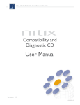
First-time Nitix Setup - Net Integrator
9.
Hard disk key lock – locks the face plate preventing physical access.
10.
Control panel – contains the display panel and all control buttons.
11.
Display panel – displays the status of the Net Integrator.
12.
Direction arrows – used to execute commands from the control panel.
13.
Enter and Cancel buttons – used to execute commands from the control panel.
14.
Backup and Restore buttons – used to initiate backup and restore procedures.
Back View
1
7
9
2
3
8
6
4
5
Please Note: The image above corresponds to our Mark I and Mark II models.
1.
Power socket – where the power cord is connected.
2.
Serial port – for an external dial-up modem.
3.
Extra ports – reserved for future use.
4.
Ethernet Port 0 – used to connect to the local area network (LAN).
5.
Ethernet Port 1 – used to connect to a LAN segment or to the Internet.
6.
Ethernet Port 2 – used to connect to a LAN segment or to the Internet.
7.
Power supply fan – provides cooling for internal components.
Nitix User Manual – Version 4.1
13