1
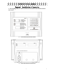
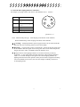
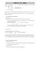
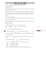
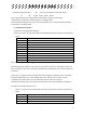
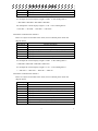
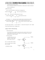
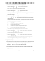
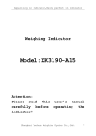
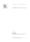
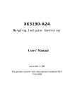
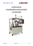
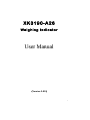
XK3190-A26
Weig hing Ind icato r
User Manual
(Version 1.01)
1
Content
Chapter 1
Technical Parameter
1
Chapter 2
Installation ………………………………………………… 2
(1)Weighing indicator front side function instruction and back side function instruction.
(2) Load cell & weighing indicator connection
Chapter 3
Operation Instruction…………………………………… 4
(1). Button function
(2). Startup&Shut down
(3). Battery use
(4). Startup Zero operation and Manual zero operation
(5) Tare operation
(6). Unit price input
(7) Accumulation clear and Accumulation display and accumulation clear
(8)Saving and re-call of unit price
(9)Power-saving mode
(10)Inner code display
Chapter4 Optional function
8
(1)RS232 communication
(2)Serial port print
(3)Scoreboard output
(4)Upper and lower limits alarming
Chapter 5 Information Instruction
14
Chapter 6 Maintenance and Attention
15
Dear user:
Please read this manual before using.
1
X K 3 1 9 0 –A26
Chapter 1 Technical Parameter
1. Model :
XK3190-A26
2. Accuracy class :
, n=3000
Class
3. A/D conversion mode:
∑-Δ
4. A/D conversion resolution: 1 million yard
5. A/D conversion speed:
10 times/second
6. Load cell excitation voltage :
7. Signal source:
8. Input signal range:
DC
3V
1 load cell(four-wire mode)
-16 mV ~18mV
9.Display:
Front side: 5+5+6 digits LCD display(white LED back light), 4 state indication
symbol,3 class battery power prompting
Back side side:5+6 digits LCD display(white LED back light),2 states
indication symbol,3 class battery power prompting
10. Keypad:
4×4 membrane key
11.AC power:
AC 220V/50 Hz
12.DC power:
built-in rechargeable 4V/4.5AH battery
13.Fuse:
0.5A
14.Warm-up time :
10 minutes
15.Operation temperature:0~40℃
16.Storage temperature: -25℃~55℃
17.External dimensions:
240*187*190
18.Net weight :
about 1.5kg
()
1
X K 3 1 9 0 –A26
Chapter2
Installation & Connection
1. A26 weighing indicator front side function instruction and back side function
instruction. :
Load cell
(2-1-1 )Front side function instruction
Fuse or extension interface
(2-1-2 )Back side function instruction
()
2
X K 3 1 9 0 –A26
2. Load cell and weighing indicator connection :
A26 adopts 5 pin plug connect with sensor, and definition are as
Foot
position
1
follows::
definition
5
1 E+
Excitation voltage +
(E+)
2
Excitation voltage (E-)
3
Signal+(S+)
4
Signal-(S-)
5
Shielding wire(SH)
(picture 2-2-1)
SH
E-
2
SS+
4
3
(picture 2-2-1)
Note:When install pole type:load cell plug in the bottom of the indicator;
When install desktop: load cell plug in the back of the indicator;
▲ !warning::Weighing indicator power supply must be cut off when install the
load cell and wire connecting must be correct and reliable.
▲ !warning :To ensure the system is working fine , please fix the plug with screw
to the indicator after the signal source wiring, the user can not insert and pull out
plug at discretion, and it is forbidden while the indicator is on .
▲ !Signal source and weighing indicator are all static electricity sensitivity
equipment,so user must adopt anti-static electricity when weighing indicator
works. To avoid the damage of the signal source and weighing indicator by
lighting strike and insure the operator's safety and correlative equipment working
well in the thunder storm season, the user must adopts credibility measures to
avoid lighting strike.
()
3
X K 3 1 9 0 –A26
Chapter 3 Operation Instruction
1.. Button function:
1.“0~9”number button
Weighing state:unit price input
State setting:parameter input
2.“Accu”button
Amount is zero:accumulation display
Amount is not zero:accumulation function
State setting:Exit button
3.“Clear”button
When there is accumulation:Clear accumulation
When there is no accumulation:Clear unit price
State setting:Confirm button
4.“Tare”button
G.W>0:The current gross weight as tare weight
G.W<=0:Clear net weight
5.“Unit price”button
6.“Zero”button
Press one time:
call unit price
Press two times:
store unit price
In Zero range:The current gross weight as Zero
Outside zero range:no effect
7.“On/Off”button
Power off state:Press button after 3 seconds,power on
Power on state:Press button after 3 seconds,power off
8.“1”+“Clear”
Press in same time: Enter into parameter setting
9.“1”+“3”
Weighing state:Enter into inner code display state
Inner code display state:Exit inner code display state
2.Startup&Shut down
(1)Startup:
Press“startup&shut down on/off”button for 2~3 seconds,indicator startup.then the
indicator will start self-test,after that, indicator will enter into weighing mode
automatically.When there is low-battery please connect with AC power and then startup.
(2)Shut down
()
4
X K 3 1 9 0 –A26
Press“on/off tartup&shut down”button for 2~3 seconds in weighing state,then the
indicator will shut down.
3.Battery use
(1)Battery charge
Indicator is turned off, connect the AC power (AC indication light is on), began to
charge the battery , the charging time is about 20 to 30 hours.
(2)Use
Start indicator without connection AC power, and the rechargeable battery inside the
indicator will supply the power to the indicator .
The indicator upper left indicates the remaining battery capacity, three grid means that
fully charged;two grid means capacity is not full;1 grid means capacity is low and need
connect to the AC power and charging at once; there is no grid means battery use out ,
the indicator will power off automatically 30 seconds later to protect the inside
battery ,please use the indicator after charging .
(3)Working time.
A26(no back light)One time charge can work around 180 hours(typical value);
A26(with back light)One time charge can work around 36 hours(typical value);
Start indicator with connection AC power, and the rechargeable battery inside will be
charged by AC power and the AC power will supply the indicator.
4.Start zero and manual zero
(1). Start zero
After self-test finished when start the indicator, if the loading of platform value is under
the full capacity 10%(relative to calibration zero point), the indicator automatically set to
zero, gross weight is displayed as 0.
(2)Manual zero
If the weight on the scale is under the full capacity 2% (relative to calibration zero point)
in weighing state,press 【zero】 key, you can put the current weight as the zero point,
gross weight is displayed as 0.
()
5
X K 3 1 9 0 –A26
5. Tare operation
(1) .Tare
In weighing state and if the gross weight is above zero and in stable state
press"tare"button and delete the current gross weight as tare weight, and display the
net weight is zero and tare indicate symbol light will on.
(2)Cancel tare
If the gross weight is zero or below zero and in the tare and also weighing state, press
【tare】can put the current gross weight to zero and the tare indicate symbol light is
off.
6.
Unit price input
(1)Input
Press 0-9 number button in weighing mode can input the unit price.
While entering the unit price, you need to press the keys within two seconds, otherwise
the indicator will automatically be cleared and re-start inputing. The unit price is "rmb/
kg", fixed to two decimal places.
(2)Clear
Method 1:2 seconds after unit price input,press“0”button,unit price clear to zero
Method 2:If the indicator not in "accu"state (accumulation indicate symbol is off),press
“clear”button,unit price clear to zero
7. Accumulate calculate, accumulate display and accumulate clear
(1) Accumulate calculate
When the amount is above zero and is stable, press 【Accumulate calculate】 button ,
you can accumulate the total amount of the current amount, the cumulative number
of times plus one, the cumulative indicate light will on.
Indicator displays【Add
】 (Accumulated reminder, 3 seconds to return
to weighing mode automatically )
【
**
【
***.**
】 (Accumulated times,up to 99 times)
】 (Accumulated amount,up to 9999.99 RMB)
After one time accumulated,you must return to below 50% of cumulative weight or
re-input the unit price to the next cumulative .
(2). Accumulative display
When the amount is zero, press “accumulate calculate”button, you can check the current
accumulate times and amount .
()
6
X K 3 1 9 0 –A26
Indicator display【totAL
】 (Accumulate display reminder,press any key to back
into the weighing state)
【
【
** 】 (Accumulate times)
***.** 】 (Accumulate amount)
(3). Accumulate clear
When indicator accumulate calculate(accumulate indicate symbol light is on),press“clear”
button can clear accumulate amount and accumulate times to zero,accumulate calculate
indicate symbol is off.
8 .Saving and re-call of unit price
(1)Unit price save
Indicator can save and call 10 unit prices, the saving method is as follows:.
First time press the number keys"0-9" to enter the unit price to be saved, then press
【unit price 】button twice.
】 (unit price save reminder)
Indicator display【SAVE
【
0】
Now press number button"0-9" to confirm the saving position , indicator will be
back to weighing state automatically after saving the data.
(2)Unit price call
press【unit price】button in weighing state.
indicator display【LoAd
【
】 (unit price call reminder)
0 】
Now press number button"0-9" to confirm the saving position, and indicator call the unit
price and then back to weighing state automatically. Press"clear"button during the unit
price saving and call, you can clear all the 10 class unit price which saving in the memory.
9. Power saving mode instruction
(1)Power saving mode
A26 indicator come into the power saving mode , the back light is off, and indicator can
do the normal weighing operation.
(2)Setting method
Press"1"and "clear"button in same time in weighing state.
()
7
X K 3 1 9 0 –A26
Indicator display【bL
【
】 (Power saving reminder)
* 】 (Original power saving mode)
Now after input the new power saving mode parameter(0~4),press“clear”confirm,
then press“Accu”back to weighing state.
(3)The meaning of power saving mode parameter
bL = 0: Close the power saving mode
bL = 1: Gross weight is 0 and indicator is stable for 3 minutes and indicator will
enter into power saving mode.
bL = 2: Display is 0 and indicator is stable for 3 minutes and indicator will enter
into power saving mode.
bL = 3: Indicator is stable for 3 minutes and indicator will enter into power
saving mode.
bL = 4: Indicator always in power saving mode .
When bL=1~3,any button or weight changes will cause the indicator to exit power
saving mode
10. Inner code display
(1)Enter the inner code display state.
Press"1"and"3"in the same time in weighing mode, and the indicator will enter into the
inner code display state.The bottom screen of the indicator show the indicator inner
code. 20 inner code is equal to a division.
Power saving options invalid in inner code display state.
(2)Exit
Press"1"and"3"in same time in inner code display state, the indicator will back to
weighing mode.
()
8
X K 3 1 9 0 –A26
Chapter4 Optional function
1.RS232 communication.
(1)Brief introduction
RS232 has 4 kinds of serial communication format of A26(see chapter4),and there are
4 kinds of baud rate can be set.
All the data are ASCII code,each group consists of 10 bits data, 1 start bit, 8 data bits, 1
stop bit. Sent once every 100ms of data. (When the baud rate is 1200 or 2400 baud rate
and communication format is 4 , maybe the interval of the transmission could more than
100ms.)
(2)Wire connecting method
Foot 3 of the air plug on the back of the indicator is TXD output, connect with the foot 2
of the computer 9 pin connector ;
Foot 5 of the air plug on the back of the indicator is GND , connect with the foot 5 of the
computer 9 pin connector;
(3)Parameter setting
① Press"1"and "Clear"button in same time in weighing state.
】 (power-saving mode chosen)
Indicator display【bL
【
*
】
Press“clear”enter into next optional function chosen.
② Indicator display【Func
【
删除的内容: chose
】 (optional function chosen)
* 】 (0~4)
0-4 stands for : invalid, RS232 communication, serial port print,scoreboard output,upper
and lower alarming.
Now input“1”and choose RS232 communication optional function and press "clear"
confirm.
③ Indicator display【tSEL
【
】 (communication format chosen)
* 】 (0~4)
tSEL = 0:Communication format 0;(detail format see next section)
tSEL = 1:Communication format 1;
tSEL = 2:Communication format 2;
tSEL = 3:Communication format 3;
Input the communication format required and then press"clear"button confirm.
()
9
X K 3 1 9 0 –A26
④ Indicator display【bAUd
【
】 (chose communication baud rate chose)
* 】 (1200、2400、4800、9600)
After input the baud rate required,press"clear"button confirm and finish the
communication parameter setting and back to weighing state.
In the parameter input process, press the "Accu"button, you can terminate the parameter
input, back to weighing mode.
1. Communication format .
Continuous communication format 0:
There are 12 bytes in each frame data, and detailed format please check the diagram as
below.
Content and Note
The X byte
1
02(XON)
2
3
symbol position
+orWeighing data(display value)
higher position
:
Weighing data
:
Weighing data
8
Weighing data
Start
:
:
low position
9
Decimal points digits
from right to left (0~4)
10
XOR checksum
11
XOR checksum
03(X0FF)
high 4 digit
low 4 digit
12
end
The confirmation of higher 4 digits and lower 4 digits XOR checksum
XOR checksum operated in 16 hex byte way from byte 2 to byte 9. The high 4 and low 4
bits of checking result was conversion and transmit in ASCII code, conversion method are
as follows:
If less than, or equal to 9, then add 30h, will send a number of ASCII code, for example:
XOR checksum high 4 to 6, after adding 30h, 36h is ASCII code for the 6 to send;
If higher than 9, then add 37h, will send a letter ASCII code, for example:
XOR checksum high 4 bits of B, plus 37h, the ASCII code for the 42h that is sending B
Continuous communication format 1:
There are 9 bytes in each frame data, and detail format please check the diagram as
below.
The X byte
1
Content and Note
=
start
2
Weighing data (display value including decimal point)lower position
:
Weighing data
:
()
10
X K 3 1 9 0 –A26
:
Weighing data
:
8
Weighing data
high position
9
0 or -
symbol position
For example the current display weight is 3.000,so the sending data is:
=000.3000=000.3000=000.3000=000.3000
For example the current display weight is -1.00,so the sending data is:
=00.1000-=00.1000-=00.1000-=00.1000-
Continuous communication format 2:
There are 9 bytes in each data of the frame, for more details please check the
diagram below.
The X byte
Contents and Notes
1
=
2
0 or -
start
symbol position
3
Weighing data( display value including decimal point) higher position
:
Weighing data
:
Weighing data
9
Weighing data
:
:
low position
For example the current display weight is 3.000,so the sending data is:
=0003.000=0003.000=0003.000=0003.000
For example the current display weight is -1.00,so the sending data is:
=-0001.00=-0001.00=-0001.00=-0001.00
Continuous communication format 3:
There are 9 bytes in each data of the frame, for more details please check the
diagram below.
The X byte
Contents and Notes
1
=
start
2
0 or -
3
Weighing data( display value including decimal point) higher position
:
Weighing data
:
:
Weighing data
:
9
Weighing data
lower position
10
;
separator
symbol position
11
Unit price(including decimal point)higher position
:
Unit price
:
()
11
X K 3 1 9 0 –A26
16
Unit price
lower position
17
;
separator
18
Amount(including decimal point) higher position
:
Amount
24
Amount
:
lower position
For example the current display weight is2.000,unit price is 1.00, amount is
2.00 ,so the sending data is:
=0002.000;001.00;0002.00; =0002.000;001.00;0002.00;
2. Serial port print
(1)Brief introduction
A26 can equipped with optional desktop micro printer, it can print SN number, gross
weight, tare, net weight, unit price, amount, accumulate times and accumulate amount.
When it accumulate successfully (press"accu"button), it can print the weight bill;
After all the weighing press"unit price"button can print accumulate times and
accumulate amount.
After print press"accumulate clear"button clear accumulate record and start the next
weighing.
Note:When adopts the optional serial port micro printer, the original indicator unit
price saving and call are invalid.
(2)Wiring method
Please use the serial port print cable which connect the indicator and desktop print
provided by our company.
(3)Parameter setting
① Press"1"and "Clear"button in same time in weighing state.
】 (Power-saving mode chosen)
Indicator display【bL
【
*
】
Press“clear”enter into next optional function chosen.
② Indicator display【Func
【
】 (optional function chose)
*
】 (0~4)
Now input “2”,choose the serial port print function and press"clear"button confirm.
()
12
X K 3 1 9 0 –A26
③ Indicator display【Prnt
【
】 (print content selection)
***** 】 (only can input 0 or 1 )
there are 5 digits from right to left, they are stand for:
The 1 digit: 0:not print SN number; 1:print SN number
The 2 digit: 0:not print gross weight;1:print gross weight
The 3 digit: 0:not print tare;
1:print tare
The 4 digit: 0:not print unit price; 1:print unit price
The 5 digit: 0:not print amount;
1:print amount
Note:Net weight must be print can not be set
After input the print content, press"clear" button confirm.
④ Indicator display【Ln
【
**
】 (Run paper lines chosen)
】 (00~99)
There are total 2 digits, high digit is weight bill run paper lines(0~9),means after print
the weight bill run paper line.
Lower digit is accumulate run paper lines(0~9),means the accumulate run paper lines
after every time print.
After enter the expected lines of run paper, press the "Clear" button to confirm, the
indicator automatically returned to weighing state.
In the parameter input process, press the "Accu" button, you can terminate the parameter
input operation and back to weighing state.
3. Scoreboard output
(1)Brief introduction
A25 can connect with our company's 1 inch, 3inch,5 inch,8inch single display
scoreboard and 3 inch three-windows scoreboard through RS232.
(2)Wiring method
①Single display scoreboard
Scoreboard modified to RS232 method
Foot 3 of the plug on the back of the indicator is TXD output, connect with the
scoreboard connect line(red line);
Foot 5 of the plug on the back of the indicator is GND,connect with the scoreboard
connect line(black line).
②Three-windows scoreboard
Please change the communication baud rate of the scoreboard to 9600
Foot 3 of the plug on the back of the indicator is TXD output, connect with the
()
13
X K 3 1 9 0 –A26
scoreboard connect line(blue line);
Foot 5 of the plug on the back of the indicator is GND,connect with the scoreboard
connect line(black line).
(3)Parameter setting
① Press"1"and "Clear"button in same time in weighing state.
】 (Power-saving mode chosen)
Indicator display【bL
【
*
】
Press“clear”enter into next optional function chosen.
② Indicator display【Func
【
】 (optional function chose)
* 】 (0~4)
Now input “3”,after choose the scoreboard output extension function then
press"clear"button confirm and then enter to the next optional function chosen.
③ Indicator display【DISP
【
】 (single window and three windows chosen)
*
】 (1、3)
Now input single window(1),three windows(3)after chosen and press“clear”button
confirm and indicator back to weighing state.
(4)Upper and lower limit alarming
<1>Brief introduction
A25 provide two point outputs of the alarm function (alarm mode can be set),
output method is transistor OC gate output (see below diagram), each of the
maximum drive current is 50mA.
<2>Wiring method
Air plug on the back of the
indicator is switch volume
signal output, which are :
Foot 1 is switch volume 1output ;
Foot 4 is switch volume 2 output
Foot 5 is GND;
<3>Parameter setting
()
14
X K 3 1 9 0 –A26
① Press"1"and "Clear"button in same time in weighing state.
】 (Power-saving mode chosen)
Indicator display【bL
【
*】
Press“clear”enter into next optional function chosen.
② Indicator display【Func
【
】 (optional function chose)
*
】 (0~4)
Now input“4”and choose upper and lower limit alarming optional function and
press "clear" confirm.
③ Indicator display【ctrL
【
**
】 (Control method chosen)
】 (High and low 2 digits,and control 2 switch volume
output separately )
Left digit control switch volume output 1, right digit control switch volume output
2, and control parameter 0~4 is selectable.
0:
Not output
1:
Greater than or equal the setting output
2:
Less than the setting output
3:
Greater than or equal the setting and stable output
4:
Less than the setting output and stable output
After input the control method parameters,press"clear"confirm.
④ Indicator display【PP1
【 *****
】 (switch volume output 1 setting point)
】
Input the setting point and press"clear"confirm.
⑤ Indicator display【PP2
【
】 (switch volume output 2 setting point)
***** 】
Input the setting point and press"clear"confirm.And now finish the upper and
lower alarming parameter setting and back to weighing state.
<4>Application examples
a、For example: Switch 1 output is effective when weight is above 1.000kg and switch 2
output is effective when weight is above 2.000kg. Not judge stabilization.
Parameters :
FunC =4;ctrL=11; PP1=1.000; PP2=2.000。
b、For example:We need a switch output volume above1.900kg and under2.100kg,
judge stabilization.
()
15
X K 3 1 9 0 –A26
Parameters :
FunC =4;ctrL=34; PP1=1.900; PP2=2.100。
Now put the switch volume 1 and 2 together as hardware to be an output.
Chapter5 Information Indication
1.
Err 03
: Overload alarming, need remove parts of the load or all of the load.
2.
Err 05
:
AD part fault, please examine and dispose as following
method:
1.Examine load cell and its connecting wire.
2.AD part broken, please send back to factory for repairing.
3.
Err 08
: Parameter input is not meet the requirements, input parameter again
4.
Err 09
:Not meet the requirement of accumulation request :instable or no zero
operation.
5.
Add
:Accumulating count, back to weighing state 3 seconds later
automatically.
6.
totAL
:Accumulating display, automatically back to weighing state after 3
seconds.
.
7.
InCodE
:Inner code display state,press“1”and “3”in same time to back to weighing state.
()
16
X K 3 1 9 0 –A26
Chapter 6 Maintenance and attention
1.To guarantee its clarity and service life, the indicator shouldn’t be placed directly under
sunshine and should be set in the plain space.
2.It is not suitable to place the indicator in the dusty and vibration environment and also
avoid using in the moist environment.
3.Signal source and weighing indicator should be reliably connected, and system should
be well grounding. It should be far away with strong electric field, strong magnetic field.
Load cell and indicator should be far away with strong corrosive, inflammable, explosive
object.
▲ Do not use under inflammable gas or inflammable steam; do not use under
pressure container canning system.
▲ Lightning frequent areas, it must be installed reliable lightning arrester, to ensure
operators safety and prevent damage of instruments and relevant equipment due to
lightning.
▲ Signal source and indicator are static sensitive equipments, when using must
earnestly adopt anti-static measure. It is prohibited in measuring device for welding
operation or other strong electric field operation; in thunderstorms season, we must
implement the reliable lightning-protection measures to prevent signal source and
the indicator damage caused by lightning strike, ensure operators safety of weighing
equipment and related equipment safety operation.
4. Never use strong solvents (e.g., benzene, nitro class oil) to clean the housing.
5. Liquid or electricity conducting particles should not be poured into the indicator, in case
the indicator damage and electric shock.
6. You should cut off power supply of indicator and relevant device before you pull-in and
out the connecting cable of indicator and external device.
▲!You should cut off power supply before pull-in and out connecting cable of signal source.
7.Output interfaces of indicator must be strictly in accordance to the user's manual, you
should not alter any connection. If there is failure when using the indicator, you
should immediately unplug it, and send to manufacturers for repair. Ordinary
non-professional manufacturers should not repair it to avoid bigger damage.
8 . Company advice for customers: start to use our indicator after test. The company is
only responsible for the quality of indicator, the biggest compensation is not more than
twice of indicator value, the company is not responsible failure of the whole system.
9. The built-in battery of indicator is a consumable part that is not within the range of "three
guarantees".
▲!In order to prolong the battery service life, ensure fully charging before using. If
indicator has not been used for a long time, it must be charged every two months,
()
17
X K 3 1 9 0 –A26
every time 20 to 25 hours.
(Note:Charging time is around 20-25 hours and the indicator must be power off)
▲!When moving or installing the indicator, you must carefully move it and avoid
strong vibration, impact or bump in order to avoid electrode in the battery being
shorted and damaged
10. Since invoice date, the indicator has a one-year free repair period. If any
non-artificially failure happens under regular using conditions within this period, the user
can send the indicator with its guarantee card (of the correct number) back to our service
station or supplier for repair. The indicator shouldn’t be open without authorization ,
otherwise free guarantee will be cancelled.
()
18