1
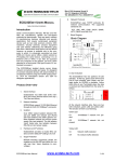
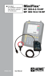
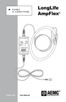
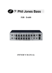
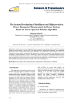
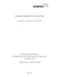
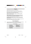
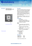
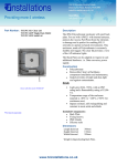
6.
ECD485ENET USERS MANUAL
ECD485Enet uses TCP/IP protocols for
network communication. The supported
standards are:
ISOLATED DEVICE SERVER
Introduction
The ECD485Enet Isolated device server brings
network connectivity safely and easily. It is designed
to connect industrial devices with serial interface to
an Ethernet network using the TCP/IP protocol family (TCP for transparent stream and UDP for
datagram applications).
TCP, UDP, ARP, ICMP, DHCP, SNMP,
HTTP, SMTP and SSL/TLS
Block Diagram
Block Diagram
screw terminals
screw terminals
LED
D+
DSGnd
LED
Isolated
Supply
Isolated
Supply
T+ 1
T-
2
R+
3
R-
4
V+
V--
Main
Supply
LED
LED
SGnd 5
5-pin Compression Terminal
Devuce Server
Field RS-485 Port
7.
Ethernet Port
Serial communications (RS-232, RS-422 and RS485) are cost-effective, reliable and time-tested
protocols for data transfer. They are used in millions
of manufacturing, banking, industrial and security
applications that require serial-based peripheral
device such as: bar code scanners, printers, CNC
machines, security cameras, process equipment
and card readers. Effectively and efficiently using
data from a stand-alone serial device can be difficult
however, as access is available only to the computer to which it is physically connected via local
COM port. Device server offers a better solution by
IP-enabling the serial device, connecting it to an
Ethernet LAN or WAN. It can then be accessed
from any computer on the network, just as if it were
attached to a local serial COM port at each PC authorized to access it.
Network Protocols
RJ45 Ethernet
Note 1: Connector type is configurable when order (option "-cr" shown)
8. User Indication
Product Over-view
1.
Serial Interface
ECD485Enet has 5-way terminal block
connector (T+, T-, R+, R- and SGnd) and a
screw terminal block at the top (D+, D- and
SGnd).
2.
The ECD485Enet has two portions of LED
indicator. At the top, green LEDs (Pwr-B and
Pwr-A) light showing main power and isolated power for RS-485 is available. Yellow
LEDs (Rcv-A and Txd-A)light when the data
is received and transmitted from the serial interface.
Network Interface
ECD485Enet support 10/100 Mbit Ethernet
through its RJ45 (10/100BaseT) connector
3.
Isolation
Over 2500v optical isolation between RS485 port and network port (RJ45) (5kv test
isolation) and 2500v galvanic isolation between RS-485 port and the power supply
(3kv test isolation).
4.
Hardware and IP address
ECD485Enet provides six bytes MAC address and the default IP setting to 0.0.0.0
5.
At the network interface side, there are two
LED indicators there, green LED and yellow
LED. The function of them is as following:
Green LED
On
sent
10/100Base-T network link pre-
Off
present
10/100Base-T network link not
Surge Protection
Yellow LED
600watt transient suppresser diodes are
installed on the RS-485 port (600w for 1ms
with less than 1psec response to overvoltage)
On
Network traffic detected
Off
No network traffic detected.
ECD485Enet User Manual
www.ecdata-tech.com
1 of 4
Green
8
Yellow
Set the network parameters for the
ECD485Enet and save them to the nonvolatile
memory.
Note: The temporary IP address by ARP is
reverted after every power reset of the
ECD485Enet. Be sure to store the parameters to
make the changes permanent.
1
2.
Serial Configuration
Follow the network configuration, select
the serial interface configuration, and set the parameters for the serial comm.
Configuration
1.
Network configuration
The ECD485Enet can be configured over
the network, the configuration is stored in nonvolatile memory and is retained without power. The
configuration can be changed anytime and the unit
performs a reset after the configuration has been
changed and stored.
To configure the unit, connection to the
unit with Web Browser must be established.
Assign a New IP Address
If the IP address of the unit is undefined,
the following steps highlight how to assign a temporary IP address over the network.
Set a static ARP with the desired IP address using the hardware address (MAC address)
of the ECD485Enet which is printed on the product
label. Following shows the use of ARP in
Win95/98/2000/me/xp/NT, (from the DOS prompt)
and UNIX environments when the MAC address of
the ECD232Enet is 00-40-9d-23-62-03.
For normal operation, the ECD485Enet
has 8 jumpers installed on board to terminate and
bias the RS-485 interface. These are only removed
when more than two units of ECD485Enet are connected to the same RS-485 wire pair. For example,
if 4 units of ECD485Enet are connected to a wire
pair, at least 2 of them must have all TT & RT
jumpers removed(read the application note for details).
Note: The unit can be selected for 2-wires or 4wires communication mode using the 2w & 4w
jumper.
Installation
1. Network Connection
There are two types of UTP Ethernet cable connection in the ECD485Enet to Ethernet connection.
One is Straight and the other is Crossover. Following figures show the connection for two types of
connections:
Device
Arp –s 192.168.2.33 00-40-9d-23-62-03
Hub
Straight-through cable
TX+
1
1 RX+
TX-
2
2
RX-
RX+
3
3
TX+
RX-
6
6
TX-
The command for most Unix systems is:
Arp –s 192.168.2.33 00:40:9d:23:62:03
Note: In order for the ARP command to
work in windows, the ARP table on the PC must
have at least one IP address defined other than its
own. If there is no other entry beside the local machine, ping another IP machine on your network to
build the ARP table. Once there is at least one entry
in the ARP table, use the above command to ARP
an IP address to the ECD485Enet
Telnet the ECD485Enet using the IP address assigned to it just now, the unit will change its
IP address to the one designated in the ARP command.
Point a web browser to the unit by entering
the IP address in the web browser’s URL Address
field.
Fig. 1. Straight-through connection
Device
PC
Crossover cable
TX+
1
1 TX+
TX-
2
2 TX-
RX+
3
3 RX+
RX-
6
6
RX-
Fig. 2. Cross-Over Connection
Http://192.168.2.33
ECD485Enet User Manual
www.ecdata-tech.com
2 of 4
Note: A pair of twisted wires must be used to connect a set of transmitter pins to their corresponding
receiver pins. DO NOT use a wire from one pair and
another wire from a different pair.
The ECD485Enet unit mounts on a standard DIN
rail as listed in the specification.
4. Jumpers Setting (default)
As a convention, EC Data suggests choosing the
darker wire (or solid color) for “+” and lighter color
(or striped) for “-“. Since the bus is bi-directional, all
terminals “+” and “-“ both transmit and receive when
appropriate. Remember, RS-485 is not a loop.
4W
2W
RB-
RT
RB+
TT
The default setting for the ECD485Enet RS-485 end
is as per following:
TB-
For 4-wire (select the 4w) RS-485, a master device
transmits on the transmit wire pair to the receive
terminals of ALL slave device. The master “T+” terminal connects to all “R+” terminals of the slave
device, and similarly all “-“ terminals connect on the
other wire. In turn, all of the slave devices share a
common receive wire pair to respond to the master
device. The slave device “T+” terminals connect to
the master “R+” and so on.
TB+
2 Serial Connections
on on on on on on off on
Note: The choice of communication mode is
either 4W (default) or 2W.
Application Example
On the ECD485Enet, the removable terminals are
labeled as “T+”, “T-“, “R+”, “R-“, “G”. Due to a space
limitation, only the transmit signals are echoed on
the top terminal as “D+”, “D-“, “Gnd”.
If you select the unit in 2W mode, only T+, T- and
Gnd will work.
It is also critical that the signal ground be properly
connected. If your RS-485 bus does not have the 5th
ground wire, then you should at least connect the
signal ground of the connected port of the
ECD485Enet to the nearest device’s digital ground
or use the shield drain wire for a “signal ground”.
The ECD485Enet will be damaged over time if this
ground is not properly connected.
Each RS-485 segment requires a 120Ohm terminating resister at each end-assuming your cable has a
characteristic impedance of 120 Ohms. Therefore a
RS-485 system will require at least 2 terminating
resisters (read the application note for details).
Below is a drawing of the ECD485Enet showing the
location of the jumpers for the RS-485. Those label
“B” are the bias jumpers, and the terminating resister is labeled “T”.
Technical Specification
1. RS-485 port description
TT
TBRB+
RT
RB2W
4W
TB+
1.1. RS-485; 4-wire Signals; T+, T-, R+, R-, Gnd.
1.2. Duplex; full duplex, direction automatic.
1.3. Speed; Up to 230,400bps; Configuration required.
1.4. Line Voltage; -7v to +12v permits +/-7Vdc
ground difference between devices.
3. Physical installation
ECD485Enet User Manual
1.5. Bias; 470 Ohm pull-up (T+ & R+), 470 Ohm
pull-down (T- & R-) jumper selectable.
www.ecdata-tech.com
3 of 4
1.6. Bus Termination; 120 Ohm jumper selectable.
6.1. Height; Width: Depth (See drawing).
1.7. Official maximum bus length; 1200m per EIA485, 500m per ISO8482.
6.2. Weight: 130g.
6.3. Terminal Capacity:
1.8. Practical maximum Bus Length; 3000m with
high quality cable and other conditions.
2.5mm strand (12AWG)
2.
4..0mm solid (12AWG)
Network interface description
2.1. Integrated 802.3 compliant 10/100 Mbit network interface
2.2. Robust on-board TCP/IP stack with comprehensive protocol support: TCP, UDP, DHCP,
SNMP, SSL3.0/TLS1.0, HTTP, SMTP, ICMP,
IGMP, ARP.
6.4. Mounting Rail:
DIN EN 50022 (35mm sym)
DIN EN 50025 (32mm asym)
Note: removal from DIN EN 50025 rail is difficult.
2.3. Easy configuration through user-friendly and
fully customizable web interface.
93 (3.7)
79 (3.1)
25 (1.0)
2.4. Embedded web server with support for custom
java applets (applet space:512KB).
2.5. Universal IP address assignment for seamless
network integration.
2.6. Secure web-based configuration using password protection and HTTPS encryption
2.7. FCC Part 15, Class B/EN 55011, Class B compliant
EN 50 022 - 7.5mm
EN 50 035
EN 50 022 - 15mm
2.8. Connector: RJ45
3.
Isolation (Per ISO/IEC 9549)
3.1. Serial port to network port; 2.5Kv(optical, 5Kv
test).
3.2. Serial port to Supply; 2.5Kv (galvanic, 3Kv test)
3.3. Network port to Supply; model “-2p” none;
model “-3p” 2.5Kv.
3.4. Encapsulant; 14,000v per mm.
4.
Power Supply
4.1. Model ECD485Enet-5v-2p: 5vdc +/-5% 350mA
4.2. Model ECD485Enet-5v-3p: 5vdc +/-5% 360mA
4.3. Model ECD485Enet-dv-2p: 9 to 36vdc; 1.7w
4.4. Model ECD485Enet-dv-3p: 9 to 36vdc; 1.8w
5.
Environmental
5.1. Ambient Operating Temperature: 0C to +60C
5.2. Ambient Storage Temperature: -40C to +100C
5.3. Relative Humidity: 10 to 90%, non condensing
5.4. Casing: fungus and termite resistant, selfextinguishing, per UL94V2.
6.
Mechanical Dimensions
ECD485Enet User Manual
www.ecdata-tech.com
4 of 4