1
User’s Manual
32
RH850 Family
Type 01 Code Flash Library
Japanese Release
ZIP file name: JP_R_FCL_RH850_T01_Vx.xx_x_E
32-Bit Single-Chip Microcontroller
Supported Devices:
RH850/F1L
All information contained in these materials, including products and product specifications,
represents information on the product at the time of publication and is subject to change by
Renesas Electronics Corporation without notice. Please review the latest information published
by Renesas Electronics Corporation through various means, including the Renesas Electronics
Corporation website (http://www.renesas.com).
www.renesas.com
Rev.1.02
Sep 2013
Notice
1.
Descriptions of circuits, software and other related information in this document are provided only to illustrate the operation of
semiconductor products and application examples. You are fully responsible for the incorporation of these circuits, software,
and information in the design of your equipment. Renesas Electronics assumes no responsibility for any losses incurred by you
or third parties arising from the use of these circuits, software, or information.
2.
Renesas Electronics has used reasonable care in preparing the information included in this document, but Renesas Electronics
does not warrant that such information is error free. Renesas Electronics assumes no liability whatsoever for any damages
incurred by you resulting from errors in or omissions from the information included herein.
3.
Renesas Electronics does not assume any liability for infringement of patents, copyrights, or other intellectual property rights of
third parties by or arising from the use of Renesas Electronics products or technical information described in this document. No
license, express, implied or otherwise, is granted hereby under any patents, copyrights or other intellectual property rights of
Renesas Electronics or others.
4.
You should not alter, modify, copy, or otherwise misappropriate any Renesas Electronics product, whether in whole or in part.
Renesas Electronics assumes no responsibility for any losses incurred by you or third parties arising from such alteration,
modification, copy or otherwise misappropriation of Renesas Electronics product.
5.
Renesas Electronics products are classified according to the following two quality grades: “Standard” and “High Quality”. The
recommended applications for each Renesas Electronics product depends on the product’s quality grade, as indicated below.
“Standard”:
Computers; office equipment; communications equipment; test and measurement equipment; audio and visual
equipment; home electronic appliances; machine tools; personal electronic equipment; and industrial robots etc.
“High Quality”: Transportation equipment (automobiles, trains, ships, etc.); traffic control systems; anti-disaster systems; anticrime systems; and safety equipment etc.
Renesas Electronics products are neither intended nor authorized for use in products or systems that may pose a direct threat to
human life or bodily injury (artificial life support devices or systems, surgical implantations etc.), or may cause serious property
damages (nuclear reactor control systems, military equipment etc.). You must check the quality grade of each Renesas
Electronics product before using it in a particular application. You may not use any Renesas Electronics product for any
application for which it is not intended. Renesas Electronics shall not be in any way liable for any damages or losses incurred
by you or third parties arising from the use of any Renesas Electronics product for which the product is not intended by Renesas
Electronics.
6.
You should use the Renesas Electronics products described in this document within the range specified by Renesas Electronics,
especially with respect to the maximum rating, operating supply voltage range, movement power voltage range, heat radiation
characteristics, installation and other product characteristics. Renesas Electronics shall have no liability for malfunctions or
damages arising out of the use of Renesas Electronics products beyond such specified ranges.
7.
Although Renesas Electronics endeavors to improve the quality and reliability of its products, semiconductor products have
specific characteristics such as the occurrence of failure at a certain rate and malfunctions under certain use conditions. Further,
Renesas Electronics products are not subject to radiation resistance design. Please be sure to implement safety measures to
guard them against the possibility of physical injury, and injury or damage caused by fire in the event of the failure of a Renesas
Electronics product, such as safety design for hardware and software including but not limited to redundancy, fire control and
malfunction prevention, appropriate treatment for aging degradation or any other appropriate measures. Because the evaluation
of microcomputer software alone is very difficult, please evaluate the safety of the final products or systems manufactured by
you.
8.
Please contact a Renesas Electronics sales office for details as to environmental matters such as the environmental compatibility
of each Renesas Electronics product. Please use Renesas Electronics products in compliance with all applicable laws and
regulations that regulate the inclusion or use of controlled substances, including without limitation, the EU RoHS Directive.
Renesas Electronics assumes no liability for damages or losses occurring as a result of your noncompliance with applicable laws
and regulations.
9.
Renesas Electronics products and technology may not be used for or incorporated into any products or systems whose
manufacture, use, or sale is prohibited under any applicable domestic or foreign laws or regulations. You should not use
Renesas Electronics products or technology described in this document for any purpose relating to military applications or use
by the military, including but not limited to the development of weapons of mass destruction. When exporting the Renesas
Electronics products or technology described in this document, you should comply with the applicable export control laws and
regulations and follow the procedures required by such laws and regulations.
10. It is the responsibility of the buyer or distributor of Renesas Electronics products, who distributes, disposes of, or otherwise
places the product with a third party, to notify such third party in advance of the contents and conditions set forth in this
document, Renesas Electronics assumes no responsibility for any losses incurred by you or third parties as a result of
unauthorized use of Renesas Electronics products.
11. This document may not be reproduced or duplicated in any form, in whole or in part, without prior written consent of Renesas
Electronics.
12. Please contact a Renesas Electronics sales office if you have any questions regarding the information contained in this document
or Renesas Electronics products, or if you have any other inquiries.
(Note 1) “Renesas Electronics” as used in this document means Renesas Electronics Corporation and also includes its majorityowned subsidiaries.
(Note 2) “Renesas Electronics product(s)” means any product developed or manufactured by or for Renesas Electronics.
(2012.4)
NOTES FOR CMOS DEVICES
(1) VOLTAGE APPLICATION WAVEFORM AT INPUT PIN: Waveform distortion due to input noise or a
reflected wave may cause malfunction. If the input of the CMOS device stays in the area between VIL
(MAX) and VIH (MIN) due to noise, etc., the device may malfunction. Take care to prevent chattering noise
from entering the device when the input level is fixed, and also in the transition period when the input level
passes through the area between VIL (MAX) and VIH (MIN).
(2) HANDLING OF UNUSED INPUT PINS: Unconnected CMOS device inputs can be cause of malfunction. If
an input pin is unconnected, it is possible that an internal input level may be generated due to noise, etc.,
causing malfunction. CMOS devices behave differently than Bipolar or NMOS devices. Input levels of
CMOS devices must be fixed high or low by using pull-up or pull-down circuitry. Each unused pin should be
connected to VDD or GND via a resistor if there is a possibility that it will be an output pin. All handling
related to unused pins must be judged separately for each device and according to related specifications
governing the device.
(3) PRECAUTION AGAINST ESD: A strong electric field, when exposed to a MOS device, can cause
destruction of the gate oxide and ultimately degrade the device operation. Steps must be taken to stop
generation of static electricity as much as possible, and quickly dissipate it when it has occurred.
Environmental control must be adequate. When it is dry, a humidifier should be used. It is recommended
to avoid using insulators that easily build up static electricity. Semiconductor devices must be stored and
transported in an anti-static container, static shielding bag or conductive material. All test and measurement
tools including work benches and floors should be grounded. The operator should be grounded using a wrist
strap. Semiconductor devices must not be touched with bare hands. Similar precautions need to be taken
for PW boards with mounted semiconductor devices.
(4) STATUS BEFORE INITIALIZATION: Power-on does not necessarily define the initial status of a MOS
device. Immediately after the power source is turned ON, devices with reset functions have not yet been
initialized. Hence, power-on does not guarantee output pin levels, I/O settings or contents of registers. A
device is not initialized until the reset signal is received. A reset operation must be executed immediately
after power-on for devices with reset functions.
(5) POWER ON/OFF SEQUENCE: In the case of a device that uses different power supplies for the internal
operation and external interface, as a rule, switch on the external power supply after switching on the internal
power supply. When switching the power supply off, as a rule, switch off the external power supply and then
the internal power supply. Use of the reverse power on/off sequences may result in the application of an
overvoltage to the internal elements of the device, causing malfunction and degradation of internal elements
due to the passage of an abnormal current. The correct power on/off sequence must be judged separately
for each device and according to related specifications governing the device.
(6) INPUT OF SIGNAL DURING POWER OFF STATE : Do not input signals or an I/O pull-up power supply
while the device is not powered. The current injection that results from input of such a signal or I/O pull-up
power supply may cause malfunction and the abnormal current that passes in the device at this time may
cause degradation of internal elements. Input of signals during the power off state must be judged
separately for each device and according to related specifications governing the device.
How to Use This Manual
Target Readers
This manual is intended for users who wish to understand the features of the Type 01
Code Flash Library for RH850 Family and to use the library in designing and
developing application systems.
Purpose
This manual is intended to give users an understanding of the correct use of the Type
01 Code Flash Library that is used for programming the code flash in RH850 Family.
Organization
This manual includes the following sections.
• Overview
• Hardware environment
• Software environment
• FCL architecture
• FCL functional specifications
• User interface
• FCL Processing Time
How to Read This Manual
It is assumed that the readers of this manual have general knowledge of electricity,
logic circuits, and microcontrollers.
• To gain a general understanding of features
-> Read this manual in order of the table of contents.
• For details on the functions of the library
-> Refer to section 5, User Interface, of this user’s manual.
The mark <R> shows major revised points.
Conventions
Data significance:
Higher-order digits to the left and lower-order digits to the right
Active low representations:
Note:
xxx (overscore over pin and signal name)
Footnote for item marked with Note in the text.
Caution:
Information requiring particular attention
Remark:
Supplementary information
Numeral representation:
Binary ... xxxx or xxxxB
Decimal ... xxxx
Hexadecimal ... xxxxH or 0xXXXX
All trademarks and registered trademarks are the property of their respective owners.
EEPROM is a registered trademark of Renesas Electronics Corporation.
RH850 Family
Type 01 Code Flash Library
Contents
Chapter 1 Introduction ................................................................................................ 7
1.1
Overview ................................................................................................................................... 7
1.2
Target Devices .......................................................................................................................... 7
1.3
Definition of Terms .................................................................................................................. 7
Chapter 2 Hardware Environment .............................................................................. 8
2.1
Code Flash ................................................................................................................................ 8
2.2
CPU Operating Frequency Configuration .............................................................................. 9
2.3
FLMD0 Pin Setting ................................................................................................................... 9
2.4
Initialization of RAM ................................................................................................................. 9
2.5
Notes on Hardware Environment ......................................................................................... 10
Chapter 3 Software Environment ............................................................................. 11
3.1
FCL Sections .......................................................................................................................... 11
3.2
FCL Resources ....................................................................................................................... 12
3.3
Notes on Software Environment .......................................................................................... 12
Chapter 4 FCL Architecture ...................................................................................... 13
4.1
System Structure ................................................................................................................... 13
4.2
Notes on FCL Architecture.................................................................................................... 14
Chapter 5 FCL Function ............................................................................................ 15
5.1
FCL Functions ........................................................................................................................ 15
5.2
Command ................................................................................................................................ 15
5.3
Basic Flowchart ...................................................................................................................... 17
5.4
Flowchart for Command Operations .................................................................................... 19
5. 4. 1 During Command Execution/During Busy ............................................................... 19
5. 4. 2 Accessing the Code Flash during Command Execution ........................................ 19
5. 5 Notes on Basic Flowchart and Command Operation ........................................................... 20
5. 6 Features ..................................................................................................................................... 21
5. 6. 1 Security Features ........................................................................................................ 21
5. 6. 2 Protection Features .................................................................................................... 21
5. 6. 3 Command Operation Sequence ................................................................................ 21
5. 6. 4 Background Operation (BGO) ................................................................................... 23
5. 6. 5 Suspend and Resume................................................................................................. 23
5. 6. 6 Interrupt Processing ................................................................................................... 25
5. 7 Notes on Individual Features................................................................................................... 25
Chapter 6 User Interface ........................................................................................... 27
6.1
Runtime Settings .................................................................................................................... 27
6. 1. 1 Note on Runtime Settings .......................................................................................... 27
6.2
Request Structure (r_fcl_request_t) Settings ..................................................................... 28
6.2.1
User Write Access ...................................................................................................... 29
6.2.2
User Read Access ...................................................................................................... 30
6.2.3
Note on Request Structure (r_fcl_request_t) Settings ........................................... 30
6.3
FCL Function Calls ................................................................................................................ 31
6.4
Data Types .............................................................................................................................. 31
R01US0069EJ0102 Rev.1.02
Sep. 30, 2013
Page 5 of 50
RH850 Family
Type 01 Code Flash Library
6.5
FCL Functions ........................................................................................................................ 32
R_FCL_Init .............................................................................................................................. 33
R_FCL_Execute ...................................................................................................................... 34
R_FCL_Handler ...................................................................................................................... 41
R_FCL_SuspendRequest ...................................................................................................... 42
R_FCL_ResumeRequest ....................................................................................................... 44
R_FCL_GetVersionString ...................................................................................................... 46
Chapter 7 FCL Processing Time ............................................................................... 47
Appendix A Revision History.................................................................................. 49
R01US0069EJ0102 Rev.1.02
Sep. 30, 2013
Page 6 of 50
RH850 Family
Chapter 1
Introduction
Type 01 Code Flash Library
Chapter 1 Introduction
1.1
Overview
The Code Flash library is free software to rewrite code flash through user programs. This software offers interface
for “device operations on code flash” such as:
- Erase
- Write
- Security
Use this manual along with the release notes included in the package of the Code Flash library and the user's
manual for the target device.
1.2
Target Devices
For the latest device information, please contact our distributors or sales representatives.
1.3
Definition of Terms
The terms used in this user’s manual are defined below.
Table 1-1
Definition of Terms
Type
Definition of Terms
Description
"Type" is an identification name representing an FCL type. Use the type corresponding to
your device.
FCL
An abbreviation of the code flash library used to control Code Flash Memory for storing data.
The RH850 Code Flash Library Type 01 is hereafter referred to as "FCL".
FDL
An abbreviation of the data flash library used to control Data Flash Memory for storing data.
FCL function
A generic term for the functions offered by the FCL.
Block number
A number which identifies a block of Flash memory.
R01US0069EJ0102 Rev.1.02
Sep. 30, 2013
Page 7 of 50
RH850 Family
Chapter 2
Hardware Environment
Type 01 Code Flash Library
Chapter 2 Hardware Environment
This chapter describes the hardware environment required for the user to rewrite Code Flash by using the FCL.
2.1
Code Flash
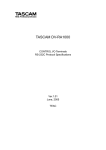
The FCL can rewrite the code flash in the RH850 family. The code flash has a block structure, and this block is a
unit of erase operation for the FCL. The code flash is always erased in units of blocks. The start address and size
must be specified for operations such as writing. An example of block structure of devices supporting this FCL is
shown below. For information about the block structure for the target device, refer to the user’s manual for the target
device.
Figure 2-1
Example of Memory Configuration: RH850/F1L with 2-Mbyte Code Flash User Area
(1 Block: 8 Kbytes/32 Kbytes)
< Address >
Block 69(32K bytes)
001F_FFFFH
001F_8000H
Block 9(32K bytes)
0001_FFFFH
0001_8000H
Block 8(32K bytes)
0001_7FFFH
0001_0000H
Block 7(8K bytes)
0000_FFFFH
0000_E000H
Block 1(8K bytes)
Block 0(8K bytes)
0000_3FFFH
0000_2000H
0000_1FFFH
0000_0000H
R01US0069EJ0102 Rev.1.02
Sep. 30, 2013
Page 8 of 50
RH850 Family
Chapter 2
Hardware Environment
Type 01 Code Flash Library
2.2
CPU Operating Frequency Configuration
To rewrite code flash through the FCL requires configuring the CPU frequency.
This frequency is used for timing calculation inside the FCL. For the procedure to configure the CPU operating
frequency, see section 6.1, Runtime Settings. Also see table 2-1, Notes on Hardware Environment.
2.3
FLMD0 Pin Setting
Some commands require setting of the FLMD0 pin to execute the FCL. Commands that need the FLMD0 pin
setting are those that may lead to the error R_FCL_ERR_FLMD0. For functions that may lead to the error
R_FCL_ERR_FLMD0, see table 6-9, status_enu of Request Structure 1/2 in section 6.
The FLMD0 pin can be controlled by the FLMDPCMD and FLMDCNT registers. For details of the FLMD0 pin
setting, see the user’s manual for the target device.
Some devices are not provided with the FLMD0 pin. For products with no FLMD0 pin, setting of the pin is not
required when the FCL is to be executed. Check whether the FLMD0 pin is provided or not in the user’s manual of
the device in use.
2.4
Initialization of RAM
There are notes on initialization of the RAM for devices to which this FCL is applied. Be sure to check table 2-1,
Notes on Hardware Environment.
R01US0069EJ0102 Rev.1.02
Sep. 30, 2013
Page 9 of 50
RH850 Family
Chapter 2
Hardware Environment
Type 01 Code Flash Library
2.5
Notes on Hardware Environment
Below are notes on the hardware environment. For details of notes other than No.1 below, be sure to see the
user’s manual for the target device.
Table 2-1
Notes on Hardware Environment
No.
1
Note
If the CPU frequency has digits below the decimal point, round it up to the nearest whole number and set this
number.
[Example] When there is no decimal point: Specify a CPU frequency 32 MHz as 32.
[Example] When there is a decimal point: Specify a CPU frequency of 25.3 MHz as 26.
2
The FCL does not perform compare check with the CPU operating frequency set by the user. The CPU
frequency is a parameter depending on the user system, and so the FCL cannot check this parameter.
Check the specifications of the target device and be sure to configure the correct CPU frequency. If checking
of the CPU frequency is required, configure the user application to perform the checking. (The FCL checks
the CPU operating frequency only within the frequency range specific to each RH850 product.)
3
Some devices have restrictions on CPU frequencies for Code Flash operation.
4
For hardware information of the Code Flash in the target device (such as a block size and unit of reading),
refer to the specifications and notes described in the user's manual for the target device.
Example) Note on reading the RH850 F1L code flash
If a blank (not written after erased) code flash is read, an ECC error is detected and an exception occurs.
Since data in the code flash when an ECC error is present is not guaranteed, use the blank check function to
check whether the code flash is blank.
5
Code flash areas that can be rewritten by the FCL may vary with the device.
Example) RH850 F1L
The user extension area cannot be rewritten by the FCL.
6
Before accessing the RAM for which ECC error detection/correction function is enabled in devices to which
this FCL is applicable, initialize the RAM to be used.
7
The FCL is only usable in supervisor mode (CPU operating mode) and cannot be used in user mode.
R01US0069EJ0102 Rev.1.02
Sep. 30, 2013
Page 10 of 50
RH850 Family
Chapter 3
Software Environment
Type 01 Code Flash Library
Chapter 3 Software Environment
This chapter describes the software environment required for the user to rewrite Code Flash by using the FCL.
3.1
FCL Sections
The functions, constants, and variables used in the FCL are allocated to the specified sections. Table 3-1,
Sections Available for the FCL , lists sections defined by the FCL. Since the code flash is not accessible during
execution of a command
Note 1
, place sections to be used during execution of a command in the on-chip RAM.
Sections for which “RAM” is specified in the “Location” column in table 3-1 are used when commands are executed.
Table 3-1
Section name
<R>
R_FCL_CONST
Sections Available for the FCL
Location
Description
Code Flash
FCL’s constant area (FCL version information)
R_FCL_CODE_ROM
FCL’s program area
Note2
R_FCL_CODE_ROMRAM
RAM
RAM area used by FCL
Note2
R_FCL_CODE_RAM
R_FCL_DATA
Note2Note3
R_FCL_CODE_RAM_USRINT
Interrupt vector during execution of a
command
Note2Note3
R_FCL_CODE_RAM_USR
Note3
R_FCL_CODE_RAM_EX_PROT
Note 1
User program that controls FCL
System reservation (only definition)
Note 1:
For information on the execution of a command, see section 5.4.1, During Execution of Command/Busy.
Note 2:
These sections can be placed in the code flash in some devices. See section 5. 6. 4, Background
Operation (BGO).
Note 3:
These sections are user sections prepared on the FCL side. Even if they are not used, their names are
referenced by the FCL in some cases. Therefore, if an error of insufficient sections occurs when linking,
define applicable sections.
R01US0069EJ0102 Rev.1.02
Sep. 30, 2013
Page 11 of 50
RH850 Family
Chapter 3
Software Environment
Type 01 Code Flash Library
3.2
FCL Resources
The table below lists the resources available for the FCL.
Table 3-1
Resources Available for the FCL (Target: GHS-Version FCL V1.01)
Resource name
Size in bytes
R_FCL_CODE_ROM section
778
R_FCL_CODE_ROMRAM section
2628
R_FCL_CODE_RAM section
3708
R_FCL_CONST section
20
R_FCL_DATA section
144
R_FCL_CODE_RAM_USRINT section
Depending on user program
Note
R_FCL_CODE_RAM_USR section
Maximum FCL stack size
164
Note : Since the user program is allocated to these sections, their sizes depend on the user program.
3.3
Notes on Software Environment
Below are notes on the software environment:
Table 3-2
Notes on Software Environment
No.
Note
1
Reserve one stack area for the user and another stack area of the size specified in table 3-2 Resources
Available for the FCL.
2
Do not destroy the FCL resources listed in table 3-2, Resources Available for the FCL.
R01US0069EJ0102 Rev.1.02
Sep. 30, 2013
Page 12 of 50
RH850 Family
Chapter 4
FCL Architecture
Type 01 Code Flash Library
Chapter 4 FCL Architecture
This chapter describes the FCL architecture required for the user to rewrite Code Flash by using the FCL.
4.1
System Structure
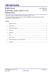
The FCL provides an interface for accessing the hardware that operates the code flash. The arrows shown in
figure 4-1, Example of System Configuration, indicate the flow of processing. Executing an FCL function from the
user application activates the hardware that controls the flash memory and operates the code flash.
Since the on-chip ROM is not accessible while a command of the FCL is being executed, programs must be
executed in the RAM.
Note1:
Note1
For execution of commands, see 5.4, Command Operation Flowchart.
Figure 4-1
System Structure
Note2
Inernal RAM
User application
Instruction
Response
FCL
Instruction
Response
Hardware
Operation
Response
Code Flash
Note2:
The FCL can be executed in the code flash of some devices. See section 5.6.4, Background Operation
(BGO).
R01US0069EJ0102 Rev.1.02
Sep. 30, 2013
Page 13 of 50
RH850 Family
Chapter 4
FCL Architecture
Type 01 Code Flash Library
4.2
Notes on FCL Architecture
Below are notes on the FCL architecture.
Table 4-1
No.
1
Notes on FCL Architecture
Note
The Code Flash cannot be read while a command of the R_FCL_Execute function is being executed
Note1
.
Before reading from the Code Flash, execute the R_FCL_Handler function to check that the command
execution has been completed. Confirm the completion of command execution by referring to "status_enu" of
the request structure
Note2
.
2
The FCL can manipulate only Code Flash. It cannot rewrite Data Flash.
3
Do not stop the supply of input clock to the X1 pin (for connection to the main clock oscillator) during Code
Flash operation. Code Flash operation needs the input clock supplied to the X1 pin.
4
Transition to power save mode (other than HALT mode) during execution of a command is prohibited.
5
The FCL and FDL should not run at the same time. While a command of the FCL is being executed, the data
flash is not accessible (readable).
Note1: The FCL can be read in the code flash of some devices. See section 5.6.4, Background Operation (BGO).
Note2 : For details of the request structure, see section 6.2, Request Structure Settings.
R01US0069EJ0102 Rev.1.02
Sep. 30, 2013
Page 14 of 50
RH850 Family
Chapter 5
FCL Function
Type 01 Code Flash Library
Chapter 5 FCL Function
This chapter describes the functional specifications of the FCL required for the user to rewrite Code Flash by
using the FCL.
5.1
FCL Functions
The table below summarizes the FCL functions offered by the FCL.
Table 5-1
FCL Functions
FCL function name
Functional overview
R_FCL_Init
Initializes the FCL, ID authentication
R_FCL_Execute
Manipulates Code Flash with commands.
R_FCL_Handler
Controls the FCL while it is running.
R_FCL_SuspendRequest
Requests the FCL to suspend.
R_FCL_ResumeRequest
Requests the FCL to return from suspended state.
R_FCL_GetVersionString
Obtains the pointer to FCL version information.
5.2
Command
The following table lists commands available for the R_FCL_Execute function.
Table 5-2 lists basic commands required for rewriting the code flash.
Table 5-2
Command name
R_FCL_CMD_PREPARE_ENV
R_FCL_CMD_ERASE
R_FCL_CMD_WRITE
R01US0069EJ0102 Rev.1.02
Sep. 30, 2013
Basic Commands
Functional overview
Prepares the FCL execution environment.
This command erases the content of the specified Code Flash
blocks.
Reads the specified number of units of data from the specified write start
address in the specified RAM area and writes them.
Page 15 of 50
RH850 Family
Chapter 5
FCL Function
Type 01 Code Flash Library
Table 5-3 lists commands that can be optionally executed by users.
Table 5-3
Optionally Executable Commands
Command name
Description
R_FCL_CMD_SET_OPB
Sets the option byte.
R_FCL_CMD_GET_OPB
Reads the set value of the set the option byte.
R_FCL_CMD_SET_RESET_VECTOR
Sets the variable reset vector
R_FCL_CMD_GET_RESET_VECTOR
Reads the value of the variable reset vector.
R_FCL_CMD_SET_LOCKBIT
Sets the lock bit. To enable the set lock bit, execute the
Note
value.
R_FCL_CMD_ENABLE_LOCKBITS command.
R_FCL_CMD_GET_LOCKBIT
Reads the value of the lock bit in the specified block.
R_FCL_CMD_ENABLE_LOCKBITS
Enables the set lock bit.
R_FCL_CMD_DISABLE_LOCKBITS
Disables the set lock bit.
R_FCL_CMD_GET_BLOCK_CNT
Obtains the total number of blocks in the code flash.
R_FCL_CMD_GET_BLOCK_END_ADDR
Obtains the end address of the specified block.
R_FCL_CMD_GET_DEVICE_NAME
Obtains the name of the device in use.
Note: For details on the option byte, variable reset vector, and lock bit, see the user’s manual for the target device.
Table 5-4 lists security commands available for the R_FCL_Execute function.Security commands can also be optionally
executed by users. For details of each security command and effects on the FCL, see the user’s manual for the target
device.
Note:See notes provided in table 5-8, Notes on Individual Features.
Table 5-4
Command name
Security Commands
Description
R_FCL_CMD_SET_OTP
Sets the One Time Programming (OTP) bit.
R_FCL_CMD_GET_OTP
Reads the value of the set OTP bit.
R_FCL_CMD_SET_ID
Sets the ID code for ID authentication.
R_FCL_CMD_GET_ID
Reads the ID code for ID authentication.
R_FCL_CMD_SET_SERIAL_ID_ENABLED
Enables the serial ID.
With this setting, the ID code for ID authentication can also be
used as a serial ID.
R_FCL_CMD_GET_SERIAL_ID_ENABLED
Reads the serial ID setting (enable/disable).
R_FCL_CMD_SET_SERIAL_PROG_DISABLED
Enables the serial programmer connection prohibition setting.
R_FCL_CMD_GET_SERIAL_PROG_DISABLED
Reads the serial programmer connection prohibition setting
(enable/disable).
R_FCL_CMD_SET_READ_PROTECT_FLAG
Sets the read command prohibition flag.
R_FCL_CMD_GET_READ_PROTECT_FLAG
Reads the read command prohibition flag.
R_FCL_CMD_SET_WRITE_PROTECT_FLAG
Sets the program command prohibition flag.
R_FCL_CMD_GET_WRITE_PROTECT_FLAG
Reads the program command prohibition flag.
R_FCL_CMD_SET_ERASE_PROTECT_FLAG
Sets the block erase command prohibition flag.
R_FCL_CMD_GET_ERASE_PROTECT_FLAG
Reads the block erase command prohibition flag.
R01US0069EJ0102 Rev.1.02
Sep. 30, 2013
Page 16 of 50
RH850 Family
Chapter 5
FCL Function
Type 01 Code Flash Library
5.3
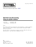
Basic Flowchart
The figure below shows the basic procedure to perform erase, write, and other operations for Code Flash by
using the FCL.
Figure 5-1
FCL Basic Flowchart
Start
(1) Initialize FCL.
Set FLMD0 pin (to 1 or 0).
User application
(2) Set FLMD0 pin (to 1).
(3) Erase
(4) Write
(5) Set FLMD0 pin (to 0).
(6) Read
Note
Yes
Rewrite other blocks?
Remarks: Error processing is omitted.
Note: (6) is optional. Execute this step only
No
End
when necessary.
The following describes steps (1) to (6) in figure 5-1, Basic Flowchart for FCL.
(1) FCL initialization
The following flowchart shows details of FCL initialization.
Figure 5-2
FCL Initialization Processing
Start
a.R_FCL_Init function
b.Copy program to RAM.
Jump to the program in the RAM.
c.Set FLMD0 pin (to 1).
d.Execute R_FCL_Execute function.
R_FCL_CMD_PREPARE_ENV command
e.Busy?
Yes
f.Execute R_FCL_Handler function.
No
g.Set FLMD0 pin (to 0).
End
R01US0069EJ0102 Rev.1.02
Sep. 30, 2013
Note: Error processing is omitted.
Page 17 of 50
RH850 Family
Chapter 5
FCL Function
Type 01 Code Flash Library
a. Execute the R_FCL_Init function to initialize the FCL execution environment. The R_FCL_Init function must be
executed only once to initialize the FCL when the user system is started up.
b. Copy the program to the RAM and jump to that program in the RAM.
c. Set the FLMD0 pin to 1.
Note 1
Note 2
d. Execute the R_FCL_Execute function (R_FCL_CMD_PREPARE_ENV command) in the RAM.
e. Check the return value. When it is R_FCL_BUSY
Note 3
, continue the command processing.
f. Then execute the R_FCL_Handler function repeatedly to proceed with command execution and finally check
command completion.
g. Set the FLMD0 pin to 0.
(2) Set FLMD0 pin (to 1)
Note 2
Note 2
Set the FLMD0 pin to 1.
(3)Erase
First, execute the R_FCL_Execute function (using the R_FCL_CMD_ERASE command).Then, execute the
R_FCL_Handler function. By repeating its execution, continue the erase operation, and finally confirm the
termination.
(4)Write
First, execute the R_FCL_Execute function (using the R_FCL_CMD_WRITE command).Then, execute the
R_FCL_Handler function. By repeating its execution, continue the write operation, and finally confirm the
termination.
(5) Set FLMD0 pin (to 0)
Note 2
Set the FLMD0 pin to 0.
Note 4
(6) Read
Read the code flash without using the FCL. Directly refer to the code flash area.Compare the read data with the
data used for writing.
Note 1:
There is a method of copying programs from the code flash to the on-chip RAM using the ROM support
feature (“ROMization”). For details, see the user’s manual for the compiler in use. The FCL can be
executed in the code flash of some devices. See section 5.6.4, Background Operation (BGO).
Example) In the case of CC-RH compiler
“ROMization” means packing initial values of variables in the data-attribute section and programs to be
allocated to the RAM in one section. By allocating this section to the ROM and calling the copy function
provided by the CC-RH, initial values and programs can be arranged in the RAM.
Note 2:
For FLMD0 pin setting, see section 2.3, FLMD0 Pin Setting. In this flowchart, the FLMD0 pin setting is
made at timings (1), (2), and (5) as an example. Set the FLMD0 pin to 1 while a command that requires
FLMD0 pin setting is being executed.
Note 3:
R_FCL_BUSY is status_enu of the request structure. For details of the request structure, see section 6.2,
Request Structure Settings.
Note 4:
Step (6) is optional. Execute this step only when necessary. While a command is being executed, the
code flash cannot be read.
R01US0069EJ0102 Rev.1.02
Sep. 30, 2013
Page 18 of 50
RH850 Family
Chapter 5
FCL Function
Type 01 Code Flash Library
5.4
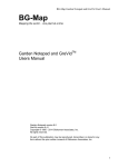
Flowchart for Command Operations
The figure below shows the basic procedure for command operation.
Figure 5-3
Basic Flowchart for Command Operations
Start
(1) R_FCL_Execute function
(2) Busy state check
Not busy
Busy
(3) R_FCL_Handler function
(4) End state check
Abnormal end
Normal end
Normal end
Error
(1) R_FCL_Execute function
Perform operations for Command.
(2) Busy state check
Check the return value. When it is R_FCL_BUSY
Note
, continue the command processing
(3) R_FCL_Handler function
Control the FCL while it is running. By repeating the execution of the R_FCL_Handler function, continue the
Command operation.
(4) End state check
If status_enu is R_FCL_OK
Note
, the operation should terminate normally. Otherwise, it should terminate with an
error.
Note:
status_enu of the request structure .For details of the request structure, see section 6.2, Request
Structure Settings.
5. 4. 1 During Command Execution/During Busy
The time period from the first execution of the (3) R_FCL_Handler function (busy) until the device leaves the busy
state after the (1) R_FCL_Execute function is executed is called “during command execution” or “during busy” in
this user’s manual.
See the time period of command execution shown in figure 5-4, Example of Command Operation Sequence.
5. 4. 2 Accessing the Code Flash during Command Execution
The code flash is not accessible during command execution. Accessing the code flash during command
execution causes the system to hang. However, the code flash in some devices is accessible. See section 5.6.4,
Background Operation (BGO).
Example) If a library such as standard library (libc.lib in the case of the CC-RH compiler) is allocated to the on-chip
ROM and the standard library is called from a program that is executing a command, the system hangs.
In this case, make settings so that a library such as standard library is not used or allocate such library to
the on-chip RAM.
R01US0069EJ0102 Rev.1.02
Sep. 30, 2013
Page 19 of 50
RH850 Family
Chapter 5
FCL Function
Type 01 Code Flash Library
5. 5 Notes on Basic Flowchart and Command Operation
The following table provides notes on the basic flowchart and command operation.
Table 5-5
Notes on the Basic Flowchart and Command Operation
No.
Note
1
The FCL does not perform timeout processing. Use the watchdog timer to provide a timeout for the FCL
functions.
2
The R_FCL_Init function must be executed only once to initialize the FCL when the user system is started up.
However, in the following case, the R_FCL_Init function can be executed again.
-- [Re-execution of the R_FCL_Init function] -In the write or erase operation, if the FCL is in the R_FCL_BUSY state even after the timeout period has
elapsed (see chapter 7, FCL Processing Time), execute the R_FCL_Init function again to stop the ongoing
write or erase operation.
To perform Code Flash operation after timeout, follow the basic procedure again starting with the R_FCL_Init
function (see figure 5-1, FCL Basic Flowchart).
R_FCL_BUSY: status_enu of the request structure
3
If a reset or power-down occurs during write or erase operation, the operation is interrupted and the contents
of the block being written or erased become undefined.
Before using the block whose contents became undefined, perform the erase operation again.
4
Before writing data to an area, be sure to erase this area.
5
It is prohibited to overwrite data in areas that have been written to.
6
The FCL does not support multitask execution.
(1)Do not execute the FCL functions during interrupt processing.
(2) Do not execute the FCL functions from multiple tasks in the OS.
7
No program can be executed in the code flash during command execution. Therefore, to execute a
program during command execution, execute it at a location other than the code flash. For details, see
section 5.4.2, Accessing the Code Flash during Command Execution. Programs are executable in the code
flash of some devices during command execution. See section 5. 6. 4, Background Operation (BGO).
8
Note:
The code flash is not readable during command execution.
For details of the request structure, see section 6.2, Request Structure Settings.
R01US0069EJ0102 Rev.1.02
Sep. 30, 2013
Page 20 of 50
RH850 Family
Chapter 5
FCL Function
Type 01 Code Flash Library
5. 6 Features
5. 6. 1 Security Features
The code flash supports the following security features. For details of each security feature and effects on the
FCL, see the user’s manual for the target device.
Note: There are notes on disabling security settings. See table 5-8, Notes on Individual Features.
Table 5-6
Security Features
Security Feature
Corresponding FCL Function or Command
ID authentication
R_FCL_Init function/R_FCL_CMD_xxx_ID command
One Time Programming (OTP)
R_FCL_CMD_xxx_OTP command
Serial programmer connection prohibition
R_FCL_CMD_xxx_SERIAL_PROG_DISABLED command
R_FCL_CMD_xxx_SERIAL_ID_ENABLED command
Block erase command prohibition
R_FCL_CMD_xxx_ERASE_PROTECT_FLAG command
Program command prohibition
R_FCL_CMD_xxx_WRITE_PROTECT_FLAG command
Read command prohibition
R_FCL_CMD_xxx_READ_PROTECT_FLAG command
Remarks: “xxx” in this table indicates SET or GET.
5. 6. 2 Protection Features
The code flash supports the following protection features. For details of each protection feature and effects on the
FCL, see the user’s manual for the target device.
Table 5-7
Protection Features
Protection Function
Corresponding Command or Pin
Block protection
Variable reset vector
R_FCL_CMD_xxx_LOCKBIT command
Note
Hardware protection
R_FCL_CMD_xxx_RESET_VECTOR command
FLMD0 pin
Remarks: “xxx” in this table indicates SET or GET.
Note:See notes provided in table 5-8, Notes on Individual Features.
5. 6. 3 Command Operation Sequence
The R_FCL_Execute function requests the device hardware to perform the relevant processing, and then
immediately returns the control to the user program. That is, the R_FCL_Execute function can operate the user
program even during command execution. Commands must be executed in the RAM. The device hardware
processing must be performed the number of required times at a trigger of calling the R_FCL_Handler function.
Each device hardware processing is suspended during the period from its completion until the next trigger. A longer
R_FCL_Handler function calling interval increases the total processing time.
To determine whether or not the operation requested from the R_FCL_Execute function has normally ended, you should
call the R_FCL_Handler function from the user application and check the device hardware operation.
R01US0069EJ0102 Rev.1.02
Sep. 30, 2013
Page 21 of 50
RH850 Family
Chapter 5
FCL Function
Type 01 Code Flash Library
The figure below shows an example of command operation sequence using the R_FCL_CMD_WRITE command.
Figure 5-4
Example of the Command Operation Sequence
User application
FCL
Device
hardware
Execution of R_FCL_Execute
Command acceptance, etc.
R_FCL_BUSY
Execution of R_FCL_Handler
R_FCL_BUSY
IDLE
Write control
Start of 1st
Command operation
Execution of R_FCL_Handler
BUSY
R_FCL_BUSY
State checkNote
during Code Flash
operation
End of 1st
Command operation
Execution of R_FCL_Handler
End of 1st Command operation
Write control
Execution of R_FCL_Handler
R_FCL_BUSY
Start of 2nd
Command operation
End of n-1th Command operation
Write control
Start of nth
Command operation
End of nth
Command operation
Execution of R_FCL_Handler
End
End response only
R_FCL_OK
(n=1,2,3,,,)
Command execution period
R01US0069EJ0102 Rev.1.02
Sep. 30, 2013
Note
Only a state check is made because
Code Flash operation is underway.
Page 22 of 50
RH850 Family
Chapter 5
FCL Function
Type 01 Code Flash Library
5. 6. 4 Background Operation (BGO)
This function allows the code flash to operate continuously during execution of a command targeted at the data
flash or the code flash. In the case of devices in which the code flash (specified area) is to be rewritten and read, the
specified code flash area is also accessible during execution of a command targeted at the code flash. For this
reason, the FCL is operable in the code flash of some devices.
For details of the BGO (such as a combination of areas to be rewritten and read, be sure to see the user’s manual
for the target device.
5. 6. 5 Suspend and Resume
[Suspend]
The suspend feature enables you to stop ongoing erase or write operations. The state of the FCL inactivated by
this feature is called FCL suspended state. Note that you can newly write memory while the FCL is in suspended
state. The suspend feature is available to stop erase or write operations only. If you attempt to use this feature to
Note
stop other operations, the FCL
is temporarily placed in R_FCL_SUSPENDED state.
Note : For details of the request structure, see section 6.2, Request Structure Settings.
[Resume]
The resume feature returns the FCL from suspended state, making it possible to resume the suspended erase or
write operation. This return from the FCL suspended state is called FCL resume.
[Timing]
After the R_FCL_SuspendRequest function is executed, a wait occurs upon one hardware operation (the device’s
operation is divided into several hardware operations). That is, after that function is executed, a delay is introduced
before a transition to FCL suspended state.
[Example of use]
<R>
If data needs to be written for emergency, the erase operation currently in progress can be suspended to write
that data.
[Flowcharts]
See the description of R_FCL_SuspendRequest and R_FCL_ResumeRequest in section 6.5, FCL Functions.
R01US0069EJ0102 Rev.1.02
Sep. 30, 2013
Page 23 of 50
RH850 Family
Chapter 5
FCL Function
Type 01 Code Flash Library
Figure 5-5
Example of FCL Suspend Operation Sequence
User application
FCL
Device
hardware
Execution of R_FCL_Execute
status_enu = R_FCL_BUSY
Command acceptance,
etc.
Execution of R_FCL_Handler
status_enu = R_FCL_BUSY
IDLE
Erase control
Start of 1st
Command operation
Execution of
R_FCL_SuspendRequest
return value = R_FCL_OK
status_enu = R_FCL_BUSY
Acceptance of
suspend command
Execution of R_FCL_Handler
status_enu = R_FCL_BUSY
Suspend control
Execution of R_FCL_Handler
Preparation of
suspend
SUSPENDE
status_enu = R_FCL_SUSPENDED
Execution of
SUSPENDED
Execution of
R FCL ResumeRequest
return value = R_FCL_OK
status_enu = R_FCL_SUSPENDED
Acceptance of
resume command
Execution of R_FCL_Handler
Resume control
Resume of erase
operation
status_enu = R_FCL_BUSY
Execution of R_FCL_Handler
BUSY
status_enu = R_FCL_BUSY
Status check only
End of 1st
Command operation
Suspend period
Note :Error processing is omitted in this figure
R01US0069EJ0102 Rev.1.02
Sep. 30, 2013
Page 24 of 50
RH850 Family
Chapter 5
FCL Function
Type 01 Code Flash Library
5. 6. 6 Interrupt Processing
Interrupt processing is also available during command execution. However, user programs and interrupt vectors
in the ROM cannot be used during command execution. The interrupt vector table and programs must be set in the
RAM by using the exception-handler address switching facility of each device. After this setting has been completed,
normal interrupt processing is performed. For details of changing the interrupt vector table, see the user’s manual
for the target device. The interrupt processing response time required during command execution is the same as
the response time during normal operation.
5. 7 Notes on Individual Features
<R>
Below are notes on the functional specifications of the FCL.
Table 5-8
Notes on the Functional Specifications of the FCL(1/2)
No.
Note
1
Note that OTP, serial programmer connection prohibition, and block erase command prohibition also disable configuration
clearing
Note
by serial programming. This setting cannot be canceled. ID authentication, program command prohibition, and read
command prohibition can be canceled by configuration clearing Note. For details, see the user’s manual for the target device.
Note: Configuration clearing is a function that initializes the ID authentication, security, protection, and option-byte settings that
are supported by serial programming.
2
You cannot use FCL functions to enable security information that has been disabled. Use the dedicated flash programmer
instead.
3
You cannot operate the FCL suspend feature concurrently in multiple operations.
4
If you suspend an erase operation and then resume it, the erase operation is performed again. In this case, however, the number
of erase operations does not increase.
5
If the suspend feature is not effective for a FCL function, a suspend request is ignored while that function is being executed.
6
Once the FCL is set to suspended state, it is terminated from suspended state after write operation. Some commands such as
“blank check” do not support the suspend feature. Even when these commands are executed, the library returns FCL suspended
state.
7
The suspend feature disables the following sequences.
<<Disabled sequences>>
・R_FCL_CMD_ERASE command --> FCL suspended state --> R_FCL_CMD_ERASE command
・R_FCL_CMD_WRITE command --> FCL suspended state --> R_FCL_CMD_ERASE command
・R_FCL_CMD_WRITE command --> FCL suspended state --> R_FCL_CMD_WRITE command
Only the following sequence is enabled.
<<Enabled sequence>>
・R_FCL_CMD_ERASE command --> FCL suspended state --> R_FCL_CMD_WRITE command
(However, the R_FCL_CMD_WRITE command is enabled only for blocks other than the block that is being erased.)
8
To use interrupts during command execution, set the interrupt vector table in the on-chip RAM by using the exception-handler
address switching facility of each device.
9
When you change the interrupt table by using the exception-handler address switching facility through the user program, consider
so that no interrupt occurs or no problem is caused by occurrence of an interrupt from the beginning to the end of the switching
procedure.
R01US0069EJ0102 Rev.1.02
Sep. 30, 2013
Page 25 of 50
RH850 Family
Chapter 5
FCL Function
Type 01 Code Flash Library
Table 5-9
No.
Notes on the Functional Specifications of the FCL(2/2)
Note
10
The code flash must not be accessed from interrupt processing during command execution.
11
FCL functions must not be executed in interrupt processing.
12
Some devices do not support the variable reset vector. Be sure to check this in the user’s manual for the target
device.
R01US0069EJ0102 Rev.1.02
Sep. 30, 2013
Page 26 of 50
RH850 Family
Chapter 6
User Interface
Type 01 Code Flash Library
Chapter 6 User Interface
This chapter describes the user interface offered by the FCL.
6.1
Runtime Settings
The fcl_descriptor.h file contains the runtime settings required for using the FCL. Some of the settings below might vary
depending on the user. So, check the settings below before configuring them.
(1)
#define FCL_CPU_FREQUENCY_MHZ
80
Set the CPU frequency. The frequency used inside the FCL is calculated from the set CPU frequency.
Note: See notes table 2-1, Notes on Hardware Environment.
(2)
#define AUTHENTICATION_ID
{ 0xFFFFFFFF, ¥
0xFFFFFFFF, ¥
0xFFFFFFFF, ¥
0xFFFFFFFF }
Set the value of an authentication ID. For details about the ID authentication, refer to the user's manual of the
target device. All initial values of ID authentication are 0xFF.
(3)
#define FCL_RAM_ADDRESS
0xFEDE0000
These settings are reserved for the system, do not change it.
6. 1. 1 Note on Runtime Settings
Table 6-1 lists a note on the runtime settings.
Table 6-1
No.
1
Note on Runtime Settings
Note
Check the following definitions in the r_fcl_descriptor.h file and set correct values.
All initial values of ID authentication are 0xFF.
#define FCL_CPU_FREQUENCY_MHZ
#define FCL_AUTHENTICATION_ID
R01US0069EJ0102 Rev.1.02
Sep. 30, 2013
Page 27 of 50
RH850 Family
Chapter 6
User Interface
Type 01 Code Flash Library
6.2
Request Structure Settings
The definitions in the figure below are called request structure.
Figure 6-1
Definition of the request structure
typedef volatile struct R_FCL_REQUEST_T {
uint32_t
command_enu;
uint32_t
bufAddr_u32;
uint32_t
idx_u32;
uint16_t
cnt_u16;
uint32_t
status_enu;
} r_fcl_request_t;
Commands are executed by a single function. Commands and data sizes are then passed to the FCL via the request
structure. The FCL state and error information are obtained via the request structure.
In subsequent sections, write access to the request structure from the user is called “user write access”, and read access to
it from the user is called “user read access”.
Figure 6-2
Request Structure
Application
command_enu
bufAddr_u32
idx_u32
cnt_u16
status_enu
User write access
FCL
User read access
The request structure is defined in the r_fcl_types.h file. It is permitted only add dummy.See note No.1 of table 6-4, Note
on the Request Structure Settings.
Figure 6-3
Alignment of Variables of the Request Structure
uint32_t command_enu;
uint32_t bufferAdd_u32;
uint32_t idx_u32;
uint16_t cnt_u16;
bit0
R01US0069EJ0102 Rev.1.02
Sep. 30, 2013
uint32_t status_enu;
bit31
Page 28 of 50
RH850 Family
Chapter 6
User Interface
Type 01 Code Flash Library
6.2.1
User Write Access
The following outlines settings for each member of the request structure at user write access. For details, see the
description of the R_FCL_Execute function in section 6.5, FCL Functions.
Table 6-2
User Write Access
Member name
Description
command_enu
Command to be set for the R_FCL_Execute function
bufferAdd_u32
Data buffer start address
1) Write command (R_FCL_CMD_WRITE)
Data buffer that contains data to be written by the user
2) Get-all commands (R_FCL_CMD_GET_x)
Note 1
Data buffer that stores data to be acquired
3) Set-all commands (R_FCL_CMD_SET_x)
Note 1
Data buffer that stores data to be set (as needed)
4) Other functions
Setting disabled
idx_u32
Note2
Index
1) Write command (R_FCL_CMD_WRITE)
Write destination address
2) Erase command (R_FCL_CMD_ERASE)
First block to be erased
3) R_FCL_CMD_SET_LOCKBIT, R_FCL_CMD_SET_OTP
Block number to be set
4) R_FCL_CMD_GET_BLOCK_END_ADDR, R_FCL_CMD_GET_LOCKBIT,
R_FCL_CMD_GET_OTP
Block number whose values are to be read
5) Other functions
Setting disabled
cnt_u16
Count
1) Write command (R_FCL_CMD_WRITE)
Number of units of write data
2) Erase command (R_FCL_CMD_ERASE)
Number of blocks to be erased
3) Other functions
Setting disabled
Note 1:
A character string following R_FCL_CMD_SET_ and R_FCL_CMD_GET_ is abbreviated as x.
Note 2:
See notes provided in table 6-4, Notes on Request Structure.
R01US0069EJ0102 Rev.1.02
Sep. 30, 2013
Page 29 of 50
RH850 Family
Chapter 6
User Interface
Type 01 Code Flash Library
6.2.2
User Read Access
This section describes the outline of status_enu settings. For details, see R_FCL_Execute Function of section 6.5,
FCL Functions.
Table 6-3
Member name
Description
status_enu
FCL state and error information.
User Read Access
status_enu is also referenced when the R_FCL_SuspendRequest or R_FCL_ResumeRequest
function is executed (as in the case of R_FCL_Execute or R_FCL_Handler).
6.2.3
Note on Request Structure Settings
Table 6-2 lists a note on the request structure settings.
Table 6-4
Note on Request Structure Settings
No.
1
Note
Do not change the position of each variable of the request structure . Variables must be aligned as shown in figure
6-3, Alignment of Variables of the Request Structure. Otherwise, the interface becomes incompatible with the
FCL.
Example: When the structure packing "-Xpack=1" of the CC-RH compiler options is used, "accessType_enu" and
"status_enu" become out of alignment by 16 bits. To avoid this problem, insert dummy data as shown below:
typedef volatile struct R_FCL_REQUEST_T {
-- omitted -uint16_t cnt_u16;
uint16_t dummy;Add this.
uint32_t status_enu;
-- omitted --
2
Every time before executing a command, check the variables of the request structure and assign values.
3
The request structure is accessed by the FCL while command execution is in progress. Do not destroy the
request structure during command execution.
4
If the R_FCL_Handler function is executed again after an error has occurred in status_enu of the request
structure, the FCL initializes the status_enu value to R_FCL_OK.
5
When setting a block in the user boot area for idx_u32 of the request structure, set (0x8000_0000 + block
number in the user boot area).
R01US0069EJ0102 Rev.1.02
Sep. 30, 2013
Page 30 of 50
RH850 Family
Chapter 6
User Interface
Type 01 Code Flash Library
6.3
FCL Function Calls
This section describes how to call the FCL functions from a user program written in C or assembly language.
- C language
When a FCL function is called from a user program in C language in the same way as a normal C function is called, the
FCL function’s parameters are passed to the FCL as arguments and the required processing is performed.
- Assembly language
Before a FCL function is called from a user program in assembly language, processing (such as parameter setup and
return address setup) is performed according to the function calling conventions for the C compiler package which is used as
development environment by the user. Then, the function is called using a jarl instruction. As a result, the FCL function’s
parameters are passed to the FCL as arguments and the required processing is performed.
Remarks
To call the FCL functions offered by the FCL from a user program, you should define the following standard header file
and include it in that program:
r_fcl. h: Standard header file
6.4
Data Types
Below are the data types of the parameters to be specified for calling the FCL functions offered by the FCL.
Table 6-5
Macro name
Data Types
Description
uint8_t
Unsigned 8-bit integers (unsigned char)
uint16_t
Unsigned 16-bit integers (unsigned short)
uint32_t
Unsigned 32-bit integers (unsigned long)
R01US0069EJ0102 Rev.1.02
Sep. 30, 2013
Page 31 of 50
RH850 Family
Chapter 6
User Interface
Type 01 Code Flash Library
6.5
FCL Functions
The subsequent sections describe the FCL functions offered by the FCL. These functions appear in the following format:
Name
Description
C language format
Pre-conditions
Post-conditions
Parameters
Parameter
Description
Return values
Value
Macro name
Description
Value
Macro name
Description
Member
Value
Macro name
Member
Value
Macro name
Commands
Reference
Settings
Others
Additional descriptions such as flowcharts
R01US0069EJ0102 Rev.1.02
Sep. 30, 2013
Page 32 of 50
RH850 Family
Chapter 6
User Interface
Type 01 Code Flash Library
R_FCL_Init
Description
This function initializes the FCL execution environment. More specifically, it initializes the following:
- Flash hardware initialization
- Confirmation of runtime settings (CPU operating frequency, ID authentication etc.)
- FCL internal variables
C language format
r_fcl_status_t R_FCL_Init( const r_fcl_descriptor_t *descriptor_pstr)
Pre-conditions
The R_FCL_Init function must be executed only once
Note
to initialize the FCL when the user system is started up.
Note: See note No.2 of table 5-5, Notes on the Functional Specifications of the FCL.
Post-conditions
None
Parameters
Parameter
Description
const r_fcl_descriptor_t *descriptor_pstr
Runtime settings pointer
Return Values
This function can return the values below.
Macro name
Value
Category
Meaning
R_FCL_OK
0x00
Cause
Action to be taken
Meaning
R_FCL_ERR_PARAMETER
0x04
Cause
Action to be taken
Meaning
R_FCL_ERR_PROTECTION
Commands
Reference
Settings
0x05
Cause
Action to be taken
Description
Processing normally ended.
Normal operation.
None
Execution of this FCL function was rejected.
Any runtime settings (excluding ID authentication)
or the argument pointer is incorrect.
Set correct values for runtime settings or the
argument pointer.
Execution of this FCL function was rejected.
The ID authentication value in runtime settings is
incorrect.
Set the correct ID authentication value.
None
R01US0069EJ0102 Rev.1.02
Sep. 30, 2013
Page 33 of 50
RH850 Family
Chapter 6
User Interface
Type 01 Code Flash Library
R_FCL_Execute
Description
This function starts command processing (including erasing and writing) for the code flash.
C language format
void R_FCL_Execute(r_fcl_request_t *request_pstr)
Pre-conditions
The R_FCL_Init function should execute and return R_FCL_OK.
・To execute a command other than R_FCL_CMD_PREPARE_ENV, R_FCL_CMD_PREPARE_ENV should have
been executed and the return value of the R_FCL_Handler function should be R_FCL_OK.
・For commands that require FLMD0 pin setting, the FLMD0 pin should be set to 1.
For FLMD0 pin setting, see section 2.3, FLMD0 Pin Setting.
Post-conditions
・After the R_FCL_Execute function normally ends, status_enu of the request structure is R_FCL_BUSY.The
execution of the R_FCL_Handler function should be repeated until status_enu of the request structure is changed
from R_FCL_BUSY to a different value.
・For commands that require FLMD0 pin setting, do not change the FLMD0 pin setting to 0 during command
execution.
Parameters
Parameter
r_fcl_request_t * request_pstr
Description
Request structure pointer
Return values
None
R01US0069EJ0102 Rev.1.02
Sep. 30, 2013
Page 34 of 50
RH850 Family
Chapter 6
User Interface
Type 01 Code Flash Library
Commands
The following table lists commands available for this function and settings for each member of the request structure.
<R>
Table 6-6
command_enu
Request Structure Settings
idx_u32
cnt_u16
R_FCL_CMD_ERASE
Erasing start block
Note 1
number
R_FCL_CMD_WRITE
Writing start
address
[256-byte aligned]
R_FCL_CMD_SET_OTP
R_FCL_CMD_GET_BLOCK_END_ADDR
R_FCL_CMD_GET_LOCKBIT
R_FCL_CMD_GET_OTP
Buffer
size
[bytes]
Setting not required
R_FCL_CMD_PREPARE_ENV
R_FCL_CMD_SET_LOCKBIT
bufferAdd_u32
Number of blocks
to be erased
Number of units of
write data
[in units of 256
bytes]
Block number to be
Note 1
set
Block number to be
Note 1
read
Block number from
which values are
Note 1
read
Start address of
data buffer that
stores data to be
written
Setting not
required
Setting not
required
R_FCL_CMD_SET_OPB
R_FCL_CMD_SET_ID
Setting not required
Setting not required
R_FCL_CMD_SET_RESET_VECTOR
256×n
Note 2
Setting not required
Start address of
data buffer that
stores data to be
acquired
Start address of
data buffer that
stores data to be
set
4
4
4
32
16
16
R_FCL_CMD_GET_OPB
32
R_FCL_CMD_GET_ID
16
4
R_FCL_CMD_GET_READ_PROTECT_FLAG
R_FCL_CMD_GET_WRITE_PROTECT_FLAG
R_FCL_CMD_GET_ERASE_PROTECT_FLAG
R_FCL_CMD_GET_SERIAL_PROG_DISABLED
Setting not required
Start address of
data buffer that
stores data to be
acquired
4
4
4
4
R_FCL_CMD_GET_SERIAL_ID_ENABLED
16
R_FCL_CMD_GET_RESET_VECTOR
4
R_FCL_CMD_GET_BLOCK_CNT
16
R_FCL_CMD_GET_DEVICE_NAME
R_FCL_CMD_SET_READ_PROTECT_FLAG
R_FCL_CMD_SET_WRITE_PROTECT_FLAG
R_FCL_CMD_SET_ERASE_PROTECT_FLAG
R_FCL_CMD_SET_SERIAL_PROG_DISABLED
Setting not required
R_FCL_CMD_SET_SERIAL_ID_ENABLED
R_FCL_CMD_ENABLE_LOCKBITS
R_FCL_CMD_DISABLE_LOCKBITS
Note 1:
See notes provided in table 6-4, Notes on Request Structure.
Note 2:
n = 1,2,3,...
Remarks: Values of items that require no setting are invalid, but set idx_u32 and bufferAdd_u32 to 0xFFFF_FFFF
and set cnt_u16 to 0xFFFF for safety design.
R01US0069EJ0102 Rev.1.02
Sep. 30, 2013
Page 35 of 50
RH850 Family
Chapter 6
User Interface
Type 01 Code Flash Library
[Examples of request structure settings]
The following provides examples of request structure settings and execution results.
(1)R_FCL_CMD_ERASE command
case 1 )
Value
idx_u32=0x2
cnt_u16=0x01
Execution result
Only block 2 of the code flash is erased.
case 2 )
Value
idx_u32=0x05
cnt_u16=0x03
Execution result
Three blocks (block 5, block 6, and block 7) of the code flash are erased.
(2)R_FCL_CMD_WRITE command
case 1 )
cnt_u16=0x0002
bufferAdd_u32=&data[0]
Note
Value
idx_u32=0x0000_4000
Execution result
512 bytes of data stored in the data buffer are written to the area that starts from address
0x0000_4000 of the code flash.
case 2 )
cnt_u16=0x0002
bufferAdd_u32=&data[0]
Note
Value
idx_u32=0x0000_4100
Execution result
512 bytes of data stored in the data buffer are written to the area that starts from address
0x0000_4100 of the code flash.
case 3 )
cnt_u16=0x01
bufferAdd_u32=&data[0]
Note
Value
idx_u32=0x0000_0001
Execution result
R_FCL_ERR_PARAMETER occurs because the value of idx_u32 is not aligned with 256.
(3)R_FCL_CMD_SET_LOCKBIT command
idx_u32=0x0000_0003
Value
Execution result The lock bit is set for block 3 of the code flash.
To enable the set lock bit, the R_FCL_CMD_ENABLE_LOCKBITS command must be executed.
(4)R_FCL_CMD_GET_BLOCK_END_ADDR command
bufferAdd_u32=&data[0]
Note
Value
idx_u32=0x0000_0005
Execution result
The end address of block 5 of the code flash is acquired and is stored in the data buffer.
(5)R_FCL_CMD_GET_LOCKBIT command
idx_u32=0x0000_0007
Execution result
The value of the lock bit of block 7 (code flash) is acquired and is stored in the data buffer.
Note:
bufferAdd_u32=&data[0]
Note
Value
Array for the data buffer named “data”
R01US0069EJ0102 Rev.1.02
Sep. 30, 2013
Page 36 of 50
RH850 Family
Chapter 6
User Interface
Type 01 Code Flash Library
[How to set data]
For how to set data for the following commands, please contact our distributors or sales representatives.
(1)R_FCL_CMD_SET_OPB command
(2)R_FCL_CMD_SET_OTP command
(3)R_FCL_CMD_SET_RESET_VECTOR command
(4)R_FCL_CMD_SET_ID command
Reference
The following table lists status_enu values of the request structure that are supported for all commands of
R_FCL_Execute and R_FCL_Handler that follows.
<R>
Table 6-7
Common status_enu
status_enu
R_FCL_OK
R_FCL_BUSY
R_FCL_ERR_FLOW
R_FCL_ERR_REJECTED
R_FCL_ERR_COMMAND
R_FCL_ERR_INTERNAL
Note
R_FCL_ERR_PARAMETER
Note
Note: These values are not available for the R_FCL_CMD_ENABLE_LOCKBITS and
R_FCL_CMD_DISABLE_LOCKBITS commands.
The following table lists commands that can only have common status_enu values listed in table 6-7.
Table 6-8
Commands That Only Have Common status_enu Values
Command
R_FCL_CMD_GET_LOCKBIT
R_FCL_CMD_GET_OPB
R_FCL_CMD_GET_ID
R_FCL_CMD_GET_OTP
R_FCL_CMD_GET_READ_PROTECT_FLAG
R_FCL_CMD_GET_WRITE_PROTECT_FLAG
R_FCL_CMD_GET_ERASE_PROTECT_FLAG
R_FCL_CMD_GET_SERIAL_PROG_DISABLED
R_FCL_CMD_GET_SERIAL_ID_ENABLED
R_FCL_CMD_GET_RESET_VECTOR
R_FCL_CMD_GET_BLOCK_CNT
R_FCL_CMD_GET_BLOCK_END_ADDR
R_FCL_CMD_GET_DEVICE_NAME
R_FCL_CMD_ENABLE_LOCKBITS
R_FCL_CMD_DISABLE_LOCKBITS
R01US0069EJ0102 Rev.1.02
Sep. 30, 2013
Page 37 of 50
RH850 Family
Chapter 6
User Interface
Type 01 Code Flash Library
Tables 6-9 and 6-10 list all combinations of commands of R_FCL_Execute and R_FCL_Handler that follows and
possible status_enu values other than those listed in table 6-7.
<R>
Command
Table 6-9 status_enu of Request Structure 1/2
status_enu
R_FCL_SUSPENDED
R_FCL_CMD_PREPARE_ENV
R_FCL_ERR_FLMD0
*●Supported
R_FCL_ERR_PARAMETER
●
R_FCL_CMD_ERASE
●
●
●
R_FCL_CMD_WRITE
●
●
●
R_FCL_CMD_SET_LOCKBIT
●
●
R_FCL_CMD_SET_RESET_VECTOR
●
●
R_FCL_CMD_SET_OPB
●
●
R_FCL_CMD_SET_ID
●
●
R_FCL_CMD_SET_OTP
●
●
R_FCL_CMD_SET_READ_PROTECT_FLAG
●
R_FCL_CMD_SET_WRITE_PROTECT_FLAG
●
R_FCL_CMD_SET_ERASE_PROTECT_FLAG
●
R_FCL_CMD_SET_SERIAL_PROG_DISABLED
●
R_FCL_CMD_SET_SERIAL_ID_ENABLED
●
Table 6-10 status_enu of Request Structure 2/2
Command
status_enu
R_FCL_ERR_WRITE
*●Supported
R_FCL_ERR_ERASE
R_FCL_ERR_PROTECTION
●
●
R_FCL_CMD_PREPARE_ENV
R_FCL_CMD_ERASE
R_FCL_CMD_WRITE
●
●
R_FCL_CMD_SET_LOCKBIT
●
●
R_FCL_CMD_SET_RESET_VECTOR
●
●
R_FCL_CMD_SET_OPB
●
●
R_FCL_CMD_SET_ID
●
●
R_FCL_CMD_SET_OTP
●
R_FCL_CMD_SET_READ_PROTECT_FLAG
●
R_FCL_CMD_SET_WRITE_PROTECT_FLAG
●
R_FCL_CMD_SET_ERASE_PROTECT_FLAG
●
R_FCL_CMD_SET_SERIAL_PROG_DISABLED
●
R_FCL_CMD_SET_SERIAL_ID_ENABLED
●
R01US0069EJ0102 Rev.1.02
Sep. 30, 2013
Page 38 of 50
RH850 Family
Chapter 6
User Interface
Type 01 Code Flash Library
The following table lists status_enu values.
Table 6-11
status_enu
R_FCL_OK
(0x00)
R_FCL_BUSY
(0x01)
R_FCL_SUSPENDED
(0x02)
R_FCL_ERR_FLMD0
(0x03)
R_FCL_ERR_PARAMETER
(0x04)
R_FCL_ERR_PROTECTION
(0x05)
R_FCL_ERR_REJECTED
(0x06)
R_FCL_ERR_FLOW
(0x07)
Description
Meaning
Processing normally ended.
Cause
Normal operation.
Action to
be taken
None.
For R_FCL_CMD_SET_ID command: A reset is required to enable the set ID.
Meaning
(When the first R_FCL_Execute is executed) Command operation has started
normally or the command is being executed.
Cause
Normal operation.
Action to
be taken
Continue operation.
Meaning
The FCL is being suspended.
Cause
Normal operation.
Action to
be taken
None.
Meaning
Execution of the FCL function was rejected.
Cause
The FLMD0 pin is not set correctly.
Action to
be taken
Stop further FCL operation and investigate the cause of the problem.
Meaning
Execution of this FCL function was rejected.
Cause
An invalid parameter was specified.
Action to
be taken
Stop further FCL operation and investigate the cause of the problem.
Meaning
Execution of this FCL function was rejected.
Cause
A prohibited command was executed for a protected area or setting.
Action to
be taken
Stop further FCL operation and investigate the cause of the problem.
Meaning
Execution of this FCL function was rejected.
Cause
Another command or FCL function is being executed.
Action to
be taken
Stop further FCL operation and investigate the cause of the problem.
Meaning
Execution of this FCL function was rejected.
Cause
The FCL has not been initialized or is in an incorrect state.
Action to
be taken
Stop further FCL operation and investigate the cause of the problem.
Meaning
Write failed.
Cause
1.Code Flash might be faulty. 2.The area to write data to might not be erased.
3. Disabled security feature cannot be enabled by the FCL function.
4. The FLMD0 pin level may not be stable.
Action to
be taken
1.If the area to write data to is not erased, erase it and then re-execute the write.
2.If the area to write data to is already erased, investigate the cause of the problem.
3. Use the dedicated flash programmer to enable the security feature.
4. If the FLMD0 pin level is unstable, correctly set the FLMD0 pin and then
re-execute the command.
R_FCL_ERR_WRITE
(0x08)
R_FCL_ERR_ERASE
(0x09)
R_FCL_ERR_COMMAND
(0x0A)
R_FCL_ERR_INTERNAL
(0x0B)
R01US0069EJ0102 Rev.1.02
Sep. 30, 2013
Request Structure status_enu Values
Category
Meaning
Erase failed.
Cause
Meaning
1.Code Flash might be faulty. 2. The FLMD0 pin level may not be stable.
1.Stop further FCL operation and investigate the cause of the problem.
2. If the FLMD0 pin level is unstable, correctly set the FLMD0 pin and then
re-execute the command.
Execution of this FCL function was rejected.
Cause
An invalid command was specified.
Action to
be taken
Stop further FCL operation and investigate the cause of the problem.
Action to
be taken
Meaning
Unexpected error that does not occur usually
Cause
1. The cause cannot be identified by the FCL.
2.The RAM used by the FCL may have been destroyed by the user program.
3.The FCL may have been destroyed.
Action to
be taken
Stop further FCL operation and investigate the cause of the problem.
Page 39 of 50
RH850 Family
Chapter 6
User Interface
Type 01 Code Flash Library
The following table shows the meaning of values acquired by the R_FCL_CMD_GET_x
Note
function.
Note : A character string following R_FCL_CMD_GET_ is abbreviated as x.
Table 6-12
Values to Be Acquired
command
Value
R_FCL_CMD_GET_LOCKBIT
R_FCL_CMD_GET_OTP
R_FCL_CMD_GET_READ_PROTECT_FLAG
R_FCL_CMD_GET_WRITE_PROTECT_FLAG
R_FCL_CMD_GET_ERASE_PROTECT_FLAG
0:
The target facility has not been
set.
1:
The target facility has been
set.
R_FCL_CMD_GET_SERIAL_PROG_DISABLED
R_FCL_CMD_GET_SERIAL_ID_ENABLED
R_FCL_CMD_GET_OPB
Currently value of the option byte
R_FCL_CMD_GET_ID
Current ID code for ID authentication
R_FCL_CMD_GET_RESET_VECTOR
Current reset vector address
R_FCL_CMD_GET_BLOCK_CNT
Total number of blocks in the code flash of the target device
R_FCL_CMD_GET_BLOCK_END_ADDR
End address of the specified block
R_FCL_CMD_GET_DEVICE_NAME
Device name
R01US0069EJ0102 Rev.1.02
Sep. 30, 2013
Page 40 of 50
RH850 Family
Chapter 6
User Interface
Type 01 Code Flash Library
R_FCL_Handler
Description
This function executes a command and confirms completion of the command execution.
C language format
void R_FCL_Handler( void )
Pre-conditions
-
The R_FCL_Init function should execute and return R_FCL_OK.
-
The R_FCL_Execute function should execute, and status_enu of the request structure should be
R_FCL_BUSY.
-
For commands that require the FLMD0 pin setting, the FLMD0 pin should be 1 continuously since the
R_FCL_Execute function was executed.
Post-conditions
-
Execute the R_FCL_Handler function repeatedly while status_enu is R_FCL_BUSY.
-
For commands that require FLMD0 pin setting, do not change the FLMD0 pin setting to 0 during command
execution.
Parameters
Return values
Commands
None
Reference
“Reference” of this function is described in combination with the R_FCL_Execute function. See “Reference” of the
R_FCL_Execute function.
Settings
None
R01US0069EJ0102 Rev.1.02
Sep. 30, 2013
Page 41 of 50
RH850 Family
Chapter 6
User Interface
Type 01 Code Flash Library
R_FCL_SuspendRequest
Description
This function requests the FCL to be suspended while it is running.
The ongoing write and erase operations are stopped. While the FCL is in suspended state, it permits further write operation.
C language format
r_fcl_status_t R_FCL_SuspendRequest( void )
Pre-conditions
-
The R_FCL_Init function should execute and return R_FCL_OK.
-
status_enu of the request structure should be R_FCL_BUSY for write or erase.
-
The FCL should not be in the suspended state.
Post-conditions
-
Execute the R_FCL_Handler function repeatedly while status_enu is R_FCL_BUSY.
Parameters
None
Return values
This function can return the values below.
Macro name
Value
Category
Meaning
R_FCL_OK
0x00
Cause
Action to
be taken
Meaning
R_FCL_ERR_FLOW
0x07
Cause
Description
The FCL suspend request was successfully accepted.
Normal operation.
None.
Execution of this FCL function was rejected.
The FCL has not been initialized or is an invalid state.
Action to
Stop further FCL operation and investigate the cause of the
be taken
problem.
Commands
None
R01US0069EJ0102 Rev.1.02
Sep. 30, 2013
Page 42 of 50
RH850 Family
Chapter 6
User Interface
Type 01 Code Flash Library
Reference
This function can assign the value below to status_enu of the request structure .
status_enu
Value
Category
Meaning
R_FCL_BUSY
0x01
Cause
Action to
be taken
Description
During command execution.
Normal operation.
Continue operation.
Settings
None
Others
“Flowchart” of this function is described in combination with the R_FCL_ResumeRequest function. See “Flowchart”
of the R_FCL_ResumeRequest function.
R01US0069EJ0102 Rev.1.02
Sep. 30, 2013
Page 43 of 50
RH850 Family
Chapter 6
User Interface
Type 01 Code Flash Library
R_FCL_ResumeRequest
Description
This function requests the FCL to return from suspended state.
C language format
r_fcl_status_t R_FCL_ResumeRequest( void )
Pre-conditions
-
The R_FCL_Init function should execute and return R_FCL_OK.
-
status_enu of the request structure should be R_FCL_SUSPENDED.
Post-conditions
The execution of the R_FCL_Handler function should be repeated until status_enu of the request structure is
changed from R_FCL_SUSPENDED to a different value.
Parameters
None
Return values
This function can return the values below.
Macro name
Value
Category
Meaning
R_FCL_OK
R_FCL_ERR_FLOW
0x00
0x07
Cause
Description
A request for return from the FCL suspended state was
successfully accepted.
Normal operation.
Action to
be taken
None
Meaning
Execution of this FCL function was rejected.
Cause
Action to
be taken
The FCL has not been initialized or is an invalid state.
Stop further FCL operation and investigate the cause of the
problem.
Commands
None
Reference
This function can assign the value below to statsu_enu of the request structure .
status_enu
Value
Category
Meaning
R_FCL_SUSPENDED
0x02
Cause
Action to
be taken
Description
The FCL is suspended.
Normal operation.
None
Settings
None
R01US0069EJ0102 Rev.1.02
Sep. 30, 2013
Page 44 of 50
RH850 Family
Chapter 6
User Interface
Type 01 Code Flash Library
Others
[Flowchart]
The figure below shows the basic flow of execution of the R_FCL_SuspendRequest and FCL_ResumeRequst
functions used to perform an example write operation for emergency.Error processing is omitted in this figure. Busy
state is checked using status_enu of the request structure.
Figure 6-4
Normal operation
FCL Suspend and FCL Resume
FCL Suspend and FCL Resume
Write operation for emergency
Start
Start
Start
R_FCL_SuspendRequest
R_FCL_Execute
R_FCL_Execute
FCL_CMD_WRITE
R_FCL_CMD_ERASE
R_FCL_Handler
R_FCL_Handler
R_FCL_BUSY
R_FCL_Handler
Busy state
check
R_FCL_BUSY
Busy state
check
R_FCL_SUSPEND
Suspend/
Resume
Emergency write
operation
Other
Other
End
R_FCL_ResumeRequest
R_FCL_Handler
R_FCL_Handler
R_FCL_SUSPEND
R_FCL_BUSY
Busy state
check
Other
Other
End
Busy state
check
R_FCL_BUSY
End
Note :Error processing is omitted in this figure
R01US0069EJ0102 Rev.1.02
Sep. 30, 2013
Page 45 of 50
RH850 Family
Chapter 6
User Interface
Type 01 Code Flash Library
R_FCL_GetVersionString
Description
This function obtains the pointer to FCL version information.
C language format
(const uint8_t*) R_FCL_GetVersionString( void )
Pre-conditions
None
Post-conditions
None
Parameters
None
Return values
This function returns the following value (type definition const uint8_t*):
Value
Macro name
Address value
None
[Format for FCL version information]
“SH850T01xxxxxYZabcD”
- xxxxx = Compiler information
- Y = System reserved area
- Z = “E” Engineer version / “V” Release version
- abc = Library version
- D = Library version (only in the case of an engineer version)
Commands
Reference
Settings
None
Flowchart
The figure below shows the basic flow of the functions.
Figure 6-5
Flow of R_FCL_GetVersionString Function Execution
Start
R_FCL_GetVersionString
End
R01US0069EJ0102 Rev.1.02
Sep. 30, 2013
Page 46 of 50
RH850 Family
Chapter 7
FCL Processing Time
Type 01 Code Flash Library
Chapter 7 FCL Processing Time
There are two types of FCL operation processing time: (1) FCL function response time and (2) hardware
execution time. Figure 7-1 below shows the relationship between FCL function response time and hardware
execution time. For details of hardware execution time, see the user’s manual for the target device.
Figure 7-1
FCL Execution Sequence (FCL’s Processing Time)
User application
Device hardware
FCL
Execution of R_FCL_Execute
R_FCL_BUSY
Command acceptance,
etc.
Execution of R_FCL_Handler
R_FCL_BUSY
Execution of R_FCL_Handler
R_FCL_BUSY
IDLE
Write control
Start of 1st Command
operation
End of 1st Command
operation
End of 1st Command operation
Write control
Start of 2nd Command
operation
End of 2nd Command
operation
FCL function response time
Hardware execution time
R01US0069EJ0102 Rev.1.02
Sep. 30, 2013
Page 47 of 50
RH850 Family
Chapter 7
FCL Processing Time
Type 01 Code Flash Library
Table 7-1 shows typical response time of each FCL function.
Table 7-1
FCL Function Response Time (excluding R_FCL_Execute, R_FCL_Handler function)
FCL Function
Response Time [µs]
R_FCL_Init
1920/fxx
R_FCL_SuspendRequest
320/fxx
R_FCL_ResumeRequest
80/fxx
R_FCL_GetVersionString
80/fxx
Note
Remarks: Target: GHS-Version FCL V1.01
Table 7-2
FCL Function Response Time (R_FCL_Execute, R_FCL_Handler function)
Command
R_FCL_Execute
Response Time [µs]
R_FCL_Handler
Note
Response Time [µs]
R_FCL_CMD_ERASE
240/fxx
400/fxx
R_FCL_CMD_WRITE
240/fxx
4960/fxx
Note
Remarks: Target: GHS-Version FCL V1.01
Note:
fxx: CPU operating frequency (MHz)
Example) When the R_FCL_CMD_ERASE command of R_FCL_Execute (fxx = 80 MHz) is executed
240/80=3 3us
For FCL execution time that is not described here, please contact our distributors or sales representatives.
R01US0069EJ0102 Rev.1.02
Sep. 30, 2013
Page 48 of 50
RH850 Family
Appendix A Revision History
Type 01 Code Flash Library
Appendix A
Rev.
Revision History
Date
Revisions
Page
0.01
2013.03.11
-
1.00
2013.06.28
Throughout
Description
First edition issued
Unified terms (e.g. categories) and modified the style (e.g. indent)
the document
9
10
11
12
13
14
16
Added explanation in section 2.3, FLMD0 Pin Setting.
Transferred description “The data flash cannot be rewritten by the FCL”
from table 2-1 to table 4-1. Added notes and explanation.
Added supplementary information.
Added sizes in table 3-2, FCL resources.
Added explanation on table 3-3, Notes on Software Environment.
Added explanation in section 4.1, System Structure. Added
supplementary information.
Added notes for table 4-1, Notes on FCL Architecture. Added
supplementary information.
Added items in table 5-3, Optionally Executable Commands, and
explanation.
Added “Set FLMD0 pin” in (1) in table 5-1, FCL Basic Flowchart. Added
17,18
“Set FLMD0 pin” in (1) Initializing FCL. Added supplementary
information.
Added supplementary information in section 5.4, Flowchart for Command
19
Operations. Added explanation in section 5.4.1, During Command/During
Busy. Added explanation in section 5.4.2, Accessing the Code Flash
during Command Execution.
Transferred description “Transition to power save mode (other than
20
HALT mode) during execution of a command is prohibited” from table
5-5, Notes on the Basic Flowchart and Command Operation, to table 4-1.
Integrated notes on multiple execution to one item. Added explanation.
22
23,24
25
Changed words in figure 5-4, Example of Command Operation
Sequence and simplified this figure.
Added section 5.6.4, Background Operation (BGO). Added detailed
description and a figure in section 5.6.5, Suspend and Resume.
Added notes on suspend/resume in table 5-8, Notes on Individual
Features.
28
Added explanation in table 6-2, User Write Access.
29
Added notes in table 6-4, Notes on Request Structure Settings.
30
Modified words in section 6.3, Calling FCL Function.
32
33
35
Added explanation of the R_FCL_Init function. Added description on
return value R_FCL_ERR_PARAMETER.
Changed the number of bytes and added items in table 6-6,
R_FCL_CMD_WRITE.
Modified and changed the example of settings.
Added a note on table 6-7, Common status_enu.
36
Added commands in table 6-8, Commands That Only Have Common
status_enu Values.
R01US0069EJ0102 Rev.1.02
Sep. 30, 2013
Page 49 of 50
RH850 Family
Type 01 Code Flash Library
Rev.
Date
Revisions
Page
1.00
2013.06.28
37
Description
Changed R_FCL_CMD_PREPARE_ENV error in table 6-9, status_enu of
Request Structure 1/2.
Exchanged the positions of R_FCL_ERR_REJECTED and
38
R_FCL_ERR_FLOWR in table 6-11. Added supplementary information on
FCL_ERR_WRITE.
1.01
2013.07.19
1.02
2013.07.31
41
Modified values.
42
Deleted unnecessary words in “Reference”.
43
Modified values and deleted unnecessary words in “Reference”.
46
Added section 7, FCL Processing Time.
12,47 Added applicable products and versions.
11
Added supplementary information on table 3-1, Sections of FCL.
23
Deleted unnecessary words.
25,26
Divided table 5-8, Notes on Individual Features. Modified words and added
supplementary information in No. 7.
35
37
38
R01US0069EJ0102 Rev.1.02
Sep. 30, 2013
Modified the buffer size in table 6-6, Request Structure Settings.
Deleted unnecessary words and added items in table 6-7, Common
status_enu.
Added targets of R_FCL_ERR_PARAMETER in table 6-9, status_enu of
Request Structure 1/2.
Page 50 of 50
奥付
RH850 Family User’s Manual
Type 01 Code Flash Library
Publication Date:
Sep 30, 2013
Rev.1.02
Published by:
Renesas Electronics Corporation
http://www.renesas.com
SALES OFFICES
Refer to "http://www.renesas.com/" for the latest and detailed information.
Renesas Electronics America Inc.
2880 Scott Boulevard Santa Clara, CA 95050-2554, U.S.A.
Tel: +1-408-588-6000, Fax: +1-408-588-6130
Renesas Electronics Canada Limited
1101 Nicholson Road, Newmarket, Ontario L3Y 9C3, Canada
Tel: +1-905-898-5441, Fax: +1-905-898-3220
Renesas Electronics Europe Limited
Dukes Meadow, Millboard Road, Bourne End, Buckinghamshire, SL8 5FH, U.K
Tel: +44-1628-651-700, Fax: +44-1628-651-804
Renesas Electronics Europe GmbH
Arcadiastrasse 10, 40472 Düsseldorf, Germany
Tel: +49-211-65030, Fax: +49-211-6503-1327
Renesas Electronics (China) Co., Ltd.
7th Floor, Quantum Plaza, No.27 ZhiChunLu Haidian District, Beijing 100083, P.R.China
Tel: +86-10-8235-1155, Fax: +86-10-8235-7679
Renesas Electronics (Shanghai) Co., Ltd.
Unit 204, 205, AZIA Center, No.1233 Lujiazui Ring Rd., Pudong District, Shanghai 200120, China
Tel: +86-21-5877-1818, Fax: +86-21-6887-7858 / -7898
Renesas Electronics Hong Kong Limited
Unit 1601-1613, 16/F., Tower 2, Grand Century Place, 193 Prince Edward Road West, Mongkok, Kowloon, Hong Kong
Tel: +852-2886-9318, Fax: +852 2886-9022/9044
Renesas Electronics Taiwan Co., Ltd.
13F, No. 363, Fu Shing North Road, Taipei, Taiwan
Tel: +886-2-8175-9600, Fax: +886 2-8175-9670
Renesas Electronics Singapore Pte. Ltd.
80 Bendemeer Road, Unit #06-02 Hyflux Innovation Centre Singapore 339949
Tel: +65-6213-0200, Fax: +65-6213-0300
Renesas Electronics Malaysia Sdn.Bhd.
Unit 906, Block B, Menara Amcorp, Amcorp Trade Centre, No. 18, Jln Persiaran Barat, 46050 Petaling Jaya, Selangor Darul Ehsan, Malaysia
Tel: +60-3-7955-9390, Fax: +60-3-7955-9510
Renesas Electronics Korea Co., Ltd.
11F., Samik Lavied' or Bldg., 720-2 Yeoksam-Dong, Kangnam-Ku, Seoul 135-080, Korea
Tel: +82-2-558-3737, Fax: +82-2-558-5141
© 2012 Renesas Electronics Corporation. All rights reserved.
Colophon 1.3
© 2013 Renesas Electronics Corporation and Renesas Solutions Corp.
Colophon 1.3
裏表紙
RH850 Family
R01US0069EJ0102