1
2^5
mi
Copyright 1989, Coolidge Marion Graves, Jr,
FOREWORD
The software discussed in this thesis was developed exclusively for
the Solid State Electronics Laboratory in the Department of Electrical
Engineering at Texas Tech University.
were written by the author.
All of the programs except one
The single exception was the program
controlling the communications between the laboratory's HP-85 Desktop
Computer and Nicolet 2090-III Digital Oscilloscope.
This program was
initially developed by Software Consulting Group of Santa Clara, CA.
In order to integrate this program into the system under
development, extensive modifications were necessary.
modifications were performed by the author.
The necessary
As a result, the present
software represents the efforts of the author and the software engineers
of Software Consulting Group.
Their efforts and assistance are greatly
appreciated and duly recognized.
I
I
11
ACKNOWLEDGEMENTS
I owe my sincerest gratitude to the many individuals without whose
contributions this work would not have been possible.
Space does not
permit me to note all of these individuals and their efforts, but
several deserve special attention.
Chief among those are members of my
committee who have acted as supporters and advisors throughout my
graduate career:
Dr. W. M. Portnoy, graduate advisor and committee
chairman, whose direction and support provided me the opportunity to
undertake and complete my graduate studies; Dr. D. L. Gustafson, primary
thesis advisor, whose efforts brought this text from dissociated
documentation to completed thesis; Dr. W. T. Ford, minor advisor, whose
instruction bridged the often disparate paths between mathematical
theory and practice, and; Dr. R. H. Seacat, Jr., whose support,
guidance, and counsel throughout my educational career, both graduate
and undergraduate, have molded my perspectives on science, engineering,
and education, and our responsibility as individuals to that society
which educated us.
To Mark S. Bavousett, I owe my eternal thanks for his energy and
diligence in serving initially as proofreader and eventually as emissary
to the university following my departure from the Lubbock area.
Without
his aid and support, all of my labors would have been for naught.
Lastly, I owe the greatest debt of gratitude to a couple whose
patience, encouragement, and financial support over the years have made
all things possible—Coolidge and Nola Graves, my parents.
Ill
TABLE OF CONTENTS
FOREWORD
ii
ACKNOWLEDGEMENTS
iii
ABSTRACT
vi
LIST OF TABLES
vii
LIST OF FIGURES
viii
VOLUME I
CHAPTER
1.
INTRODUCTION
2
2 . SYSTEM COMPONENTS
2 .1
Introduction
6
2 .2
Data Acquisition Capabilities
7
2.2.1
Slow Measurement Capabilities
8
2.2.2
Intermediate Measurement Capabilities
9
2.2.3
Fast Measurement Capabilities
9
2.2.4
Very Fast Measurement Capabilities (Hand Entry).
2 .3
3.
Data Storage Capabilities
10
11
2. 4
Hardcopy Output Capabilities
12
2.5
System Computational Capabilities
13
2. 6
Summary
13
SYSTEM INTERACTION
15
3 .1
Introduction
15
3.2
Data Acquisition Subsystems
16
3.2.1
Slow Measurement Subsystem
16
3.2.2
Intermediate Measurement Subsystem
18
3.2.3
Fast Measurement Subsystem
21
3.2.4
Very Fast Measurement Subsystem (Hand Entry)....
22
3. 3
3.4
3. 5
4.
6
Hardcopy Output Subsystem
M a t h e m a t i c a l Conditioning Subsystem
Summary
26
28
SYSTEM TUTORIAL
4 .1
24
29
Introduction
29
IV
4.2
Slow Measurement Subsystem Tutorial
32
4.3
Intermediate Measurement Subsystem Tutorial
34
4.4
Fast Measurement Subsystem Tutorial
40
4.5
Very Fast Measurement Subsystem Tutorial (Hand E n t r y ) .
46
4.6
Hardcopy Output Subsystem Tutorial
4.7
Mathematical Processing Subsystem Tutorial
4.8
5.
Summary
57
59
SYSTEM ACCURACY
61
5 .1
Introduction
61
5.2
Analysis of Acquisition System Accuracy
61
5.2.1
Definitions of A/D Conversion Accuracy
62
5.2.2
Errors in Successive-Approximation A/D
Conversion
63
5.2.3
Errors in Direct Conversion A/D Processes
65
5.2.4
HP System Voltmeter Measurements
66
5.2.5
Nicolet Digital Oscilloscope Measurements
66
5.2.6
Tektronix Programmable Digitizer Measurements...
67
5.2.7
HP Graphics Tablet Measurements
68
5.3
Analysis of Data Conditioning Accuracy
69
5.3.1
System Time Resolution
69
5.3.2
Computational Accuracy
71
5.3.3
Value Selection Accuracy
76
5.4
6.
51
Summary
77
SUMMARY AND CONCLUSIONS
79
SELECTED BIBLIOGRAPHY
83
APPENDICES
A.
PROGRAM LISTINGS
84
B.
PROGRAM PROTECTION CODES
211
VOLUME II
C.
USER' S MANUAL
216
ABSTRACT
This thesis discusses the development of a data acquisition and
conditioning system including the definition of laboratory needs,
subsystem and system development phases, system tutorial, and error
analysis of the completed system.
Three (3) realized system goals are:
(1) relative ease of use; (2) use of a variety of data acquisition
hardware, and; (3) timely data reduction.
The design used an HP-85 computer as the controller for digitizing
hardware which included:
an HP 9111A Graphics Tablet, a Tektronix 7612D
Programmable Digitizer, a Nicolet 2090-III Digital Oscilloscope, and an
Hewlett-Packard 3437A System Voltmeter.
These components allow the
system to digitize data over the range from 10 picoseconds per sample to
27.775 minutes per sample.
VI
LIST OF TABLES
3.1
Conparison of Con9>onent and Subsystem C a p a b i l i t i e s
28
5.1
SuitBnary of P r o c e s s i n g A c c u r a c i e s
"76
t
•
Vll
LIST OF FIGURES
3.1
Slow Measurement Subsystem
17
3.2
Intermediate Measurement Subsystem
19
3.3
Fast Measurement Subsystem
21
3.4
Very Fast Measurement Subsystem
3.5
Hardcopy Output Subsystem
24
3. 6
Data Conditioning Subsystem
26
3 .7
Trapezoidal Approximation
27
Vlll
(Hand Entry)
23
VOLUME I
CHAPTER 1
INTRODUCTION
Conqputers have been a key to the advance of science and engineering
since their inception.
The computer has managed to enhance this
progress by allowing scientists and engineers to carry out computations
that would have been measured in man-months rather than in milliseconds.
This revolution has not been utilized solely by the theoreticians.
As
technology has advanced, conputers have become a mainstay in the
laboratory.
There they have proven of inestimable value.
Though initially devised to aid in calculation, the conputer has
come to be a very powerful controller.
As a controller, the computer
has become a centerpiece in the experimental laboratory.
Using the
technology available at the present time, experimentalists can use the
computer to control measurements which would have been impossible
otherwise.
At present, a growing inqpetus exists to supplant former measurement
techniques and equipment with more sophisticated, confuter-aided
techniques and computer-controlled hardware.
This is due to the fact
that when properly programmed, a coziputer can remove a great deal of the
problems associated with laboratory work.
Some of the problems
associated with experimental laboratory work are:
(1) experiments which
require long observation times; (2) short period events which are
aperiodic; (3) analog-to-digital conversions to make possible
calculations, and; (4) simple human error.
Of the problems noted, the final problem is the most prevalent.
Human error arises in many cases where laboratory conditions similar to
problem areas (1), (2), and (3), exist.
In these cases, the accuracy
and attentiveness of a computer are needed.
Where computers are
utilized in the experimental process to replace the human element, they
can all but eliminate the first three (3) problem areas.
After all,
with proper ventilation and with well-conditioned power (no large power
3
transients and adequate capacity), a computer can run for an indefinite
time.
The same cannot be said of humans.
Besides, with the aid of the
computer in the laboratory, a human can focus on other areas of
interest.
Based on the premise of removing as much human error as possible
while addressing the needs to acquire and to store data as effectively
as possible, the Solid State Electronics Laboratory in the Department of
Electrical Engineering at Texas Tech University under the direction of
Dr. W. M. Portnoy chose to develop such a data acquisition and
conditioning system.
In addition to the broader problems noted
previously, the graduate students in the laboratory, especially in the
study of second-breakdown characteristics of semiconductors, found the
volumes of data generated in the experiments difficult to process.
In the experiments, measurements of voltage and current were taken.
From these measurements, the values for power and energy were
calculated.
Without the aid of a computer, the students were faced with
the arduous task of reducing the data by hand.
At best, the graphical
analysis techniques were inaccurate and time-consuming.
Thus, large
amounts of data could be taken and stockpiled though little could be
reduced to useful data—never in a timely manner.
Therefore, the work to be discussed in this thesis was undertaken to
develop a centralized data acquisition and conditioning system (DACS).
This DACS was to answer three (3) objectives:
(1) develop a system which was easy to use by an operator who has
minimal exposure to a computer;
(2) develop a system which can utilize effectively several pieces
of data acquisition hardware;
(3) develop a system which can carry out calculations based on
measurements in a timely manner.
In the following pages, these three (3) objectives will be discussed and
the system developed to implement them will be considered.
Chapter 2 examines more closely the needs of the laboratory, and
defines specific components to answer these needs.
This will include a
discussion of the critical areas of interest present and future.
4
Chapter 3 examines the interactive subsystems developed using the
specific components designated in Chapter 2.
The discussion will
develop a more complete analysis of the needs of laboratory at the
subsystem level of interaction.
Chapter 4 provides the reader with a tutorial of each of the
subsystems.
In so doing, the reader is taken through each of the
processes that are available at the present time.
The endeavor of this
portion of the thesis is to illustrate to the reader the step-by-step
processes of the system, and thereby, provide a working framework for
any measurements which the reader may desire to make.
Chapter 5 provides the results of several tests undertaken after the
final assembly of the system.
These tests were performed to establish
effective benchmarks of the effectiveness and accuracy of the data
acquisition and conditioning system.
Chapter 6 provides a final summary analysis of the system.
In the
final chapter, the author provides a comparison between the system
capabilities and the objectives set forth in this chapter.
In addition,
the author develops a framework for developing the next generation of
data acquisition system for this laboratory.
In so doing, the author
defines the areas where the system can be improved to provide a more
substantial aid to the graduate students carrying out work within the
laboratory.
Areas of expansion ranging from enhanced graphics to
artificial intelligence are discussed.
In addition, the reader is provided with several appendices to
further document the work that was done.
Appendix A of the thesis is a
fully commented listing for each of the software programs within the
system.
Prior to each of these program listings is an abstract
describing the function of the specific software program.
Appendix B is a description of the program protection system.
In
this appendix to the thesis, the reader is provided with a description
of the program protection codes.
This is done to provide the reader
with the information necessary to edit any of the software programs on
the system.
Undoubtedly, occasions will arise where the needs of the
laboratory will exceed the limitations of the present system.
Therefore, a reader will find the necessity to edit programs in the
5
system, or write new pieces of software.
However, the author admonishes
the reader to carefully document any changes to the software for the
user that will follow.
Appendix C is a user's manual developed as a separate document for
working with the system.
This appendix includes a description of each
of the programs used by the system.
These descriptions are detailed
analyses of the workings of each of the software programs which the
system accesses.
Also, the data storage file format is discussed in
detail to provide the reader with the knowledge necessary to develop
software which can be used in conjunction with the data files which are
created by the system.
The reader also will find a number of appendices attached to the
user's manual.
These appendices include a flow chart for startup of the
system, a table of the present equipment addresses, a listing of the
error codes which can be generated by the system, and a detailed set of
flow charts documenting the logical flow of the system.
CHAPTER 2
SYSTEM COMPONENTS
2.1
Introduction
In developing an adecjuate data acquisition and conditioning system
for the Solid State Electronics Laboratory, the scope of work carried
out at the lab was examined.
From this examination, the needs for data
acquisition, storage, and manipulation, were defined, and solutions
inst riomented.
The Solid State Electronics Laboratory has carried out work in a
number of areas in recent years.
These activities range from
fabrication to characterization to reliability studies.
Some process
times were on the order of weeks; while other measurements involved
characteristics on the order of a few nanoseconds.
Thus, a flexible
system was necessary which could acq[uire data from a few nanoseconds to
a few weeks.
This involved the development of a system incorporating a
number of data acquisition units with a wide range of capabilities.
In addition, the system needed to have the capability to store the
data acquired on permanent media.
preserved of all measurements.
In this manner, a record was
Therefore, old measurements and data
could be recalled and reprinted at any future time.
longer dependent only upon a single hardcopy result.
The work was no
Also, data storage
facilitated calculations based on the data.
The system also was designed to support some limited data
conditioning activities.
At the time of this work, software was
developed for calculating products and time integrals of products from
the data.
A final recjuirement of the system was the entry of data taken prior
to the development of the data acquisition system, data external to the
Solid State Electronics Laboratory, and data acquisition beyond the time
resolution capabilities of the ecjuipment on the system.
This was to
facilitate entry of any data which was of importance to a program.
7
Thus, the system needed to have access to old data, publications and
outside work, and very fast transient data.
The system was designed to address the needs outlined previously, as
well as, the three (3) objectives outlined in Chapter 1.
The following
text examines in detail the specific needs of the laboratory and the
system components which address these needs.
into sections concerning:
The discussion is broken
1) data acquisition capabilities; 2) data
storage capabilities; 3) hardcopy output capabilities; 4) data
conditioning capabilities.
2.2
Data Acqpiisition Capabilities
As noted earlier, the laboratory needed a system capable of making
measurements with characteristic times of nanoseconds to weeks.
In
order to do this, several different data acquisition units were used.
The needs for the data acquisition equipment were broken into four (4)
time regimes.
The first time regime is defined as slow measurements.
These
measurements involve data taken at intervals of minutes over a period of
up to several weeks.
This type of data acquisition is necessary for the
reliability studies described previously where sample component
characteristics, e.g., current and voltage, are monitored over several
days.
The slow measurements are useful in experiments where component
characteristics, such as capacitance, change over several seconds and
are monitored at intervals of a few milliseconds.
This type of data
acquisition is needed in studying trapping levels and recombination
times in discrete devices.
A second time regime is defined as intermediate measurements.
These
measurements involve data taken at intervals of milliseconds down to
hundreds of nanoseconds.
This type of data acquisition is necessary for
any characteristic with a risetime of 1 microsecond or greater.
One
piece of work which needed this data acquisition was a study on the
switching characteristics of thyristors.
A third time regime is defined as fast measurements.
These
measurements involve data taken at intervals down to 5 nanoseconds.
This sanqpling time allows resolution of phenomena with risetimes on the
8
order of 50 nanoseconds.
This type of data acquisition was used in the
study of second-breakdown characteristics in semiconductors.
The final time regime is defined as very fast measurements.
These
measurements involve data taken at intervals of less than 5 nanoseconds.
In the previous three (3) time regimes, digital data acquisition
equipment with the capabilities noted did exist.
However, sanqple rates
of greater than 200 megaseuc^les per second are not financially
attractive.
by hand.
Instead, a data entry device was chosen to enter other data
This allows analog data, such as photographs, with very fast
risetimes to be digitized.
Thus, this data acquisition process allows
entry of very fast data, as well as, data acquired prior to the
development of the system and data acquired outside the laboratory.
This data acquisition process was needed in the study of the switching
characteristics of avalanche transistors.
There, the risetimes were on
the order of 1 nanosecond.
2.2.1
Slow Measurement Capabilities
The units chosen for the slow measurements were the HP3497A Data
Acquisition/Control Unit (DACU) and the HP3437A Digital Voltmeter (DVM).
The DACU has a variety of modules which can be plugged into the unit.
The modules include both digital and analog capabilities for
controlling, and monitoring, inputs and outputs.
The module used for
this work was an analog module.
The module has three (3) analog inputs which can be selected
individually.
The selected channel is transferred to the DVM.
The DVM
then measures the voltage on the line and outputs the value to the
computer.
The DVM has an accuracy of 3 1/2 digits with voltage ranges of
10 V, IV, and .1 V.
Thus, the DVM can measure cpaantities down to
several millivolts.
However, in order to measure a large voltage, e.g.,
150 V, some type of attenuation is necessary.
The DACU is used primarily as a timer to switch to channels in its
analog module,
while the DACU can switch once every 100 milliseconds,
the analog line has a finite settling time.
Experimentation showed that
approximately .5 second was necessary from the time a channel was output
9
to the DVM to the time when the DVM was triggered.
the measurement was reliable.
equipxtent.
This insured that
Thus, there is a finite delay due to the
This delay is programmed into the software discussed later.
2.2.2—Intermediate Measurement Capabilitiea
The unit chosen for the intermediate measurements was the Nicolet
2090-III Digital Oscilloscope (referred to as the Nicolet).
was designed as a digital storage oscilloscope.
The Nicolet
In the version
purchased by the Solid State Electronics Laboratory, the Nicolet has an
on-board floppy disk for permanent storage.
The Nicolet can store up to eight (8) 512-sample traces in volatile
memory.
These sample tiioes are selectable down to 500 nanoseconds.
In
addition, the Nicolet allows traces to be stored which are a sum or a
difference of the two (2) inputs.
Although the Nicolet can save eight (8) traces, this work only used
two (2) of the traces.
The software controlling the transfer of data
from the Nicolet to the conputer was purchased from Software Consulting
Group of Santa Clara, California.
This software then was modified
extensively to facilitate its use by the laboratory.
In addition to its use as a controlled data acquisition unit, the
Nicolet can be used as a free running oscilloscope.
The machine was
designed to function as a normal oscilloscope with its enhanced storage
capabilities.
Thus, the Nicolet can be used freely off-line from the
system for any number of experiments.
2u.2u^
Fast Measurement Capabilities
The unit chosen for the fast measurements was the Tektronix 7 612D
Programmable Digitizer (referred to as the 7 612D).
designed as a single-shot storage device.
The 7 612D
was
The unit purchased for the
laboratory had two (2) programmable dual channel plug-ins.
The 7612D has two (2) programmable time bases with sampling times
which range down to 5 nanoseconds.
The time bases also feature the
ability to store sixteen (16) programmable points (called breakpoints)
where the sample times can be changed.
If, for example, a 1-millisecond
sq[uare wave is to be characterized very closely, the 7612D can be
10
programped to take data at 5-nanosecond intervals for the first 256
points, at 10-microsecond intervals for the subsequent 96 points, and at
5-nanosecond intervals for the remaining points.
Thus, the risetime and
fall time of the square wave can be measured very accurately without the
need for an extraordinarily large memory capacity.
The 7612D can store two (2) traces.
nuniber of data points:
Each trace has a progreunmable
256, 512, 1024, or 2048.
Using this large
memory capacity with the previously described breakpoints, a very
flexible measurement system was developed.
In addition, the 7612D has one (1) progreunmable trigger and one (1)
plug-in for each time base.
Thus, two (2) traces can be taken
simultaneously which have very different time characteristics.
The
possibility also exists to use all 4096 points in a single sweep by
triggering time base B at the end of the time base A sweep.
This
capability, however, is not utilized on the system.
Although the 7612D can store two (2) 2048-point traces, only 1024
points per curve are transferred to the computer.
limited memory space on the computer.
This is due to the
The capabilities of the system
software will be more closely examined in Chapter 3.
2.2.4
Very Fast Measurement
Capabilities (Hand Entry)
As mentioned in section 2.2, this process is not truly a
measurement.
Instead, the HP 9111A Graphics Tablet was chosen to carry
out the hand-entered process.
Thus, the time resolution was no longer
restricted to the capabilities of a digital data acquisition unit.
Analog data acquisition methods could be capitalized upon by allowing
hand entry of data.
Thus, the data which could be accessed by the
system was essentially unlimited.
However, since the data entered was digitized by hand, the problem
of human error arose.
obtainable.
This seemed an acceptable trade-off for the data
Besides allowing entry of very fast transient data, the
operator could enter data taken prior to development of the system, and
data acquired outside of the laboratory.
11
The tablet has two (2) active areas for digitization.
bounded by a grey line on the board.
active platen.
The first is
This area is referred to as the
When the point of the pen is depressed within this area,
the tablet outputs the coordinates associated with the pen's location.
The second area at the top of the tablet is subdivided into a set of
sixteen (16) smaller areas.
softkeys.
Each of these areas are referred to as
When the point of the pen is depressed within these areas,
the tablet outputs the softkey associated with the pen's location.
These areas are programmed to indicate menu selections in the operation
of the system.
All digitized data are transferred to the computer.
The
assignment of the softkeys, and the storage of the digitized points, is
under software control.
The one disadvantage of the tablet may be its mode of operation.
The tablet uses field strength to approximate the pen's location.
If
the pen is depressed over a conductive material, e.g., pencil lead, the
field is distorted.
measurement.
Thus, the tablet could take an inaccurate
Investigation of this effect showed that the tablet
interpreted the center of the conductive area to be the pen's location.
Thus, if a 1" X 1" piece of conductive material was placed on the
tablet, digitizing almost any location on that area produced the same
result--coordinates associated with the center.
Care is required,
therefore, not to use conductive materials on the tablet.
2.3
Data Storage Capabilities
In addition to the data acquisition capabilities described, a data
acquisition system needed mass storage capabilities.
The computer
chosen for the central processor of the system was an HP85 desktop
computer.
This decision was based upon availability of the machine and
ease of programming.
In addition, the computer had a built-in mass
storage unit—a magnetic tape drive.
However, storage and access of data using a magnetic tape tended to
be rather time-consuming.
Therefore, an additional mass storage unit
was chosen, the HP9895A Flexible Disk Drive.
This unit has two (2) disk
drives which are accessible to the computer.
Each flexible disk can
12
hold over 1.18 megabytes of information.
This coxrpares to the 210
kilobyte capacity of a magnetic tape.
Aside from data storage, the disk drives are used to store the
progr2uns controlling each of the operations performed by the system.
Due to the limited memory of the conputer, the software was configured
into a set of stand-alone progreuns. Each progreuii controls a particular
operation; for exanple, there is a program for controlling the Tektronix
7612D.
Since the software was developed as a set of programs, the time
advantage of the disk drive again became apparent.
floppy disk can be loaded and run much faster.
Programs stored on a
The disk drives can
transfer data at an average rate of 23 kilobytes per second.
In
comparison, the tape drive can transfer data at a mere 650 bytes per
second.
Thus, the disk drive proved to be indispensable in the function
of the system.
Since the disk drive has two (2) units, one is
designated as the program drive and the other is designated as the data
drive.
Z^
Hardcopy Output Capabilities
A necessary support component for the data acquisition and storage
capabilities was the HP7470A Plotter.
speed and accuracy.
This plotter was chosen for its
The plotter served to complement the hardcopy
capabilities of the computer.
The computer has an on-board thermal printer/plotter.
plotter is used primarily for its print capabilities.
This printer/
In several of the
software packages, the printer is used to create hardcopy output for the
operator.
In addition, the graphic display can be dumped to the
printer/plotter.
However, the graphic display performs a direct dump to the printer/
plotter.
Therefore, the resulting plot was limited to the resolution
obtainable on the computer's small screen.
In contrast, the plots which can be generated on the HP7470A Plotter
are high resolution.
the plotter.
Therefore, all hardcopy plots are created using
Also, the plotter is used as a slow printer.
The software
13
to be discussed later uses the plotter in a print mode to list secondbreakdown characteristics based upon the processed data files.
A further preference for the plotter arose from the printer/plotter
paper lifetime.
Any hardcopy saved on the thermal paper used by the
conputer was found to fade over time.
This fading did not require
extended exposure to light, but appeared to require only time.
Thus,
hardcopies made with the plotter on normal typing paper have a longer
lifetime; while hardcopies made on the thermal printer/plotter paper
disappear after several months.
2.5
System Computational Capabilitiea
A final requirement of the system was the development of software to
carry out limited calculations.
The software which carried out these
operations is described in detail in Chapter 3.
In brief, the software
was developed to compute instantaneous power given a current curve and a
voltage curve.
power curve.
The software then calculates the time integral of the
Then, these curves—current, voltage, power, and energy—
are stored on the selected media.
2.6
Summary
The Solid State Electronics Laboratory had specific needs for a data
acc[uisition system.
goals.
This system needed to answer three (3) co-equal
The system needed to be:
1) user friendly; 2) flexible, and;
3) efficient and timely.
To obtain these goals, the specific requirements for past, present,
and future work were examined.
In so doing, the author defined the
basic capabilities required of an effective data accjuisition and
conditioning system.
These capabilities were:
1) data acquisition
capabilities; 2) data storage capabilities; 3) hardcopy output
capabilities; 4) limited computational capabilities.
The topic of data acquisition capabilities was further defined by
examining various time regime recpairements.
classified as:
These time regimes were
1) slow measurements—100 milliseconds per sample and
greater; 2) intermediate measurements—500 nanoseconds to 100
milliseconds per sample; 3) fast measurements—5 nanoseconds to 500
14
nanoseconds per san^le; 4) very fast measurements—less than 5
nanoseconds per szunple.
Based upon the classifications and reqpiirements noted, a set of
equi{»nent was gathered to acconplish the system goals.
These units were
chosen specifically for their capabilities and the manner in which their
capabilities fulfilled system requirements.
In Chapter 3, the software
controlling these conponents will be examined and their interactivity
will be documented.
CHAPTER 3
SYSTEM INTERACTION
3uJ.
Introduction
In Chapter 2, the author examined the needs of the Solid State
Electronics Laboratory.
In so doing, the task of developing a data
acquisition and conditioning system was broken into a discrete number of
subtasks. These subtasks describe the principal functions to be carried
out by the system.
In turn, individual pieces of equipment were
identified to support these functions.
In the following chapter, the
software developed to support and control the prescribed equipment will
be exeunined.
Selected components were chosen to support various data acquisition,
data storage, data output, and data conditioning activities.
However,
these con^onents cannot carry out the described activities without
interaction with other components.
system, several subsystems exist.
Thus, within the framework of the
These subsystems are grouped
according to the needs of the particular tasks.
cjuite similar to those outlined in Chapter 2.
basic areas of activity:
conditioning.
The subsystem tasks are
There exist three (3)
1) data acquisition; 2) data output; 3) data
Data storage is not a separate function in and of itself.
This is due to the fact that data storage is an integral portion of all
activities.
Within the area of data acquisition, there are four (4) separate
areas of interest.
These areas are based upon the time regimes
described in Chapter 2.
acquisition areas:
Separated by time regime, again, are the data
1) slow measurements; 2) intermediate measurements;
3) fast measurements; 4) very fast measurements and other hand entries.
Each of these areas are covered by a subsystem configured around the
equipment described in Chapter 2.
In addition to the requirements described in Chapter 2, a desire was
expressed to monitor slowly changing phenomena during tests using the
15
16
fast and intermediate measurement subsystems.
As will be pointed out in
the following sections, the fast and intermediate measurements take a
relatively short time for acquisition and transfer.
However, the data
storage process, transfer from conqputer to data storage media, takes a
great deal longer.
During this time, slowly changing phenomena such as
temperature, can be monitored using the slow measurement system.
In the
following text, each of the subsystems will be exeunined in detail.
3.2
Data Acquisition .<;iiK«»y«i-oin.^
As described in Chapter 2, there were four (4) separate time regimes
which were needed for the conplete development of this data accjuisition
and conditioning system.
these time regimes.
Discrete subsystems were designed for each of
These subsystems are conqposed of:
1) the system
conponent(s) described in the appropriate section in Chapter 2, e.g.,
slow measurement system components are the HP3497A Data Acquisition/
Control Unit and the HP3437A System Voltmeter, which perform data
acquisition; 2) the HP85 Desktop Conputer which performs control and
processing; 3) the HP9895A Flexible Disk Drive which serves as data
storage.
Therefore, within the system, there exist four (4) different data
acquisition subsystems—one for each time regime.
In addition, the
intermediate and fast measurement subsystems were designed to use the
slow measurement data acquisition elements.
This was to answer the
request for additional monitoring of slowly changing phenomena, such as
tenqperature or humidity.
3.2.1
Slow Measurement Subsystem
The slow measurement subsystem was developed using the HP85 Desktop
Coirqputer, the HP9895A Flexible Disk, the HP3497A Data Acquisition/
Control Unit (DACU), and the HP3437A System Voltmeter (DVM).
These
units are tied together using the software package named HP-DAS.
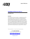
3.1 shows the block diagram of the slow measurement subsystem.
Figure
17
HP3497A
HP3437A
Data Acquisition/
* * * * ^^
System Voltmeter
Control Unit
1.11^ 1. 1. 1. t^ 1. r^:i
HP9895A
HP85
HP Interface
1^.1 t'g'
Desktop Coinputer
Flexible Disk Drive
Bus (HPIB)
Figure 3.1.
Slow Measurement Subsystem
The software was developed to take four (4) curves with 256 points
per curve. The software was designed to select a channel on the DACU.
This channel is transferred to the DVM.
Then, the coiqputer triggers the
DVM, and inputs the measurement.
This process is carried out at operator selected intervals.
The
operator chooses a sauri^ling interval from 2 seconds to 27.775 minutes.
The maximum delay is limited by the DACU; while the minimum delay is
limited by the DVM.
As pointed out in section 2.2.1, the DACU can sample as quickly as
once every 100 milliseconds.
However, the software was designed with
the premise that more than one (1) channel would be monitored.
Since
approximately .5 second is needed for a voltage to settle once channels
are changed, the software was written with a .5-second delay between
readings.
This practice is to insure an accurate reading for each
sanqple.
The data accjuisition proceeds for a period selected by the operator.
For example, the operator can take measurements every 5 seconds over a
period of 3 minutes; 36 sanples will be taken.
Since the program can
store 256 points, the operator has a limit on the size of period for the
18
measurements.
Thus, if the operator chooses a 5-second sample time, the
operator can continue the process a maximum of 21 minutes, 20 seconds.
The data accjuired by the computer is a voltage.
Thus, when the data
acquisition is completed, the conputer will ask for any conversion
factors in the process.
This is to allow the operator to condition the
data to reflect the measurement of interest, e.g., current, prior to
storage.
After the conversion factor is entered, the conqputer stores
the conditioned data in the chosen mass storage media.
If more than two (2) channels are monitored, the conputer will
recjuest the operator to input pairs of curves.
This is done because the
mathematical processing program can only process a file with two (2)
input curves.
This data accjuisition process is described in more detail in Chapter
4.
In section 4.2.1, a sample experiment is performed with the human/
machine interaction documented.
This exanple was designed as a tutorial
for use of this program, HP-DAS,, including conputer prompts and operator
responses.
For further details regarding this program, refer to:
A, Program Listings/
"HP-DAS,"
1) Appendix
and; 2) Appendix c. User's Manual,
Chapter 9, "System Multiplexer and Voltmeter Control Package."
3.2.2
Intermediate Measurement Subsystem
The intermediate measurement subsystem was developed using the HP85
Desktop Computer, the HP9895A Flexible Disk, the Nicolet 2090-III
Digital Oscilloscope (Nicolet).
software package named N I C - 8 5 .
These units are tied together using the
in addition, the intermediate
measurement subsystem was developed with an option to use the slow
measurement subsystem described in section 3.2.1.
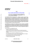
Figure 3.2 shows the
block diagram of the intermediate measurement subsystem.
The software is groomed to accept four (4) curves with 1024 point
per curve.
The software is a highly modified version of a program
purchased from Software Consulting Group, as noted in section 2.2.2.
This program was primarily fashioned to function as a transfer network.
The operator sets the time base, channels, trigger functions, etc., at
19
the front panel of the N i c o l e t .
Once the s e t t i n g s are con^sleted, the
operator takes a measurement.
HP3497A
HP3437A
Data Acquisition/
fc VI\\ i s a
System Voltmeter
Control Unit
HP Interface
Bus (HPIB)
Nicolet 2090-III
HP9895A
HP 85
Digital
X3CS
Desktop Computer
^^s
Flexible Disk Drive
Oscilloscope
Figure 3.2.
Intermediate Measurement Subsystem
Once the operator has obtained a trace worthy of storage, the
operator notifies the computer to transfer the data.
total memory capacity of 4096 points.
between the traces.
The Nicolet has a
This capacity is divided ecjually
If one (1) trace is taken, all 4096 points are used
by that trace; if four (4) traces are taken, 1024 points are used by
each curve.
The Nicolet can be set to take 1, 2, 4, or 8 traces.
The software was designed to enter a representative group of points
from the trace.
This was done using a secjuential skip.
If there are
1024 points in a curve, all points are entered and zero (0) points are
skipped; if there are 4096 points in a curve, 1/4 of the points are
entered and 3 of every 4 points are skipped—every fourth point is
entered.
The data accjuired by the conqputer is a voltage.
Thus, when the data
accjuisition is coit^leted, the computer asks for any conversion factors
in the process.
This is to allow the operator to condition the data to
reflect the measurement of interest, e.g., current, prior to storage.
After the conversion factor is entered, the computer stores the
conditioned data in the chosen mass storage media.
20
If more than two (2) channels are monitored, the conputer recjuests
the operator to input pairs of curves.
This is done because the
mathenatical processing prograua can only process a file with two (2)
input curves.
As mentioned earlier, the slow measurement subsystem is also
available for use.
If the slow measurement subsystem is desired, it is
used during the storage phase of the intermediate measurement process.
As the data is being stored, the software takes a measurement from the
voltmeter.
This is done once every 256 storage cycles.
The interval of once every 256 storage cycles was arrived at because
the program size allowed room for only 64 data points to be taken.
Thus, under the greatest load on the system, there are two (2) curves to
be stored with 1024 points each.
y-coordinate.
Each point has an x-coordinate and a
Therefore, there are 4096 storage operations.
With a maximum auxiliary storage capacity of 64 points, and a desire
to monitor four (4) channels, the software was left with 16 monitoring
times.
Subdividing 4096 storage operations into 16 ecjual portions left
a sairple interval of once every 256 storage cycles.
This provides a
sanqpling rate with approximately ecjuivalent time steps throughout the
sweep.
Also, the limited available space made necessary the development of
an auxiliary processing program, yUAUX.
This program takes care of the
processing and storage of the auxiliary voltage measurements. 32(i&mL
loads automatically and runs if the slow measurement options are
exercised.
This data accjuisition process is described in more detail in Chapter
4.
In section 4.2.2, a san^le experiment is performed with the human/
machine interaction documented.
This example was designed as a tutorial
for use of this program, NIC-BS^ including computer pron^ts and operator
responses.
For further details regarding this program, refer to:
1) Appendix
A, Program Listings, "NIC-85," and; 2) Appendix C, User's Manual,
Chapter 8, "Nicolet Digital Oscilloscope Control Package."
21
3.2.3—Fast Measurement Subsystem
The fast measurement subsystem was developed using the HP85 Desktop
Computer, the HP9895A Flexible Disk, the Tektronix 7612D Programmable
Digitizer (7 612D).
These units are tied together using the software
package named 7612D.
In addition, the fast measurement subsystem was
developed with an option to use the slow measurement subsystem described
in section 3.2.1.
Figure 3.3 shows the block diagram of the fast
measurement subsystem.
HP3497A
HP3437A
Data Acquisition/
System Voltmeter
HP Interface
Control Unit
Bus (HPIB)
Tektronix 7612D
HP85
HP9895A
Desktop Com puter
Flexible Disk Drive
Digitizejr
Figure 3.3.
Fast Measurement Subsystem
The software was designed to accept two (2) curves with 1024 points
per curve.
Much like the intermediate measurement subsystem, the fast
measurement subsystem functions as a transfer network.
Again, the
operator enters the settings on the front panel of the 7 612D.
Unlike the intermediate measurement subsystem, however, once the
7612D is set up, the operator notifies the computer to take control.
From that point forward, the computer controls the process.
computer arms the 7 612D and awaits a sweep.
The
Once a sweep is acquired,
the computer asks if the sweep is to be stored.
If not, the computer
returns control to the operator and waits for the operator to acquire a
good sweep.
The data accjuired by the computer is a voltage.
Thus, when the data
acquisition is completed, the computer asks for any conversion factors
22
in the process.
This is to allow the operator to condition the data to
reflect the measurement of interest, e.g., current, prior to storage.
After the conversion factor is entered, the con^uter stores the
conditioned data in the chosen mass storage media.
As mentioned earlier, the slow measurement subsystem is also
available for use.
If the slow measurement subsystem is desired, it is
used during the storage phase of the fast measurement process.
As the
data is being stored, the software takes a measurement from the
voltmeter.
This is done once every 256 storage cycles.
This cycle is
based upon the same considerations as noted in section 3.3.2.
This data accjuisition process is described in more detail in Chapter
4.
In section 4.2.3, a sanqple experiment is performed with the human/
machine interaction documented.
This exan^le was designed as a tutorial
for use of this program, 76120, including conputer pronpts and operator
responses.
For further details regarding this program, refer to:
1) Appendix
A, Program Listings, "7612D," and; 2) Appendix C, User's Manual^ Chapter
7, "Using Tektronix 7612D As A Single-shot 0-scope."
3.2.4
Very Fast Measurement
Subsystem (Hand Entry)
The very fast measurement subsystem was developed using the HP85
Desktop Computer, the HP9895A Flexible Disk, and the HP9111A Graphics
Tablet.
These units are tied together using the software package named
TABLET•
Figure 3.4 shows the block diagram of the very fast measurement
subsystem.
Unlike the preceding three (3) subsystems, this data accjuisition
subsystem was not designed to control a real-time data taker.
Instead,
this subsystem is centered around a hand-entry digitizer.
The software was developed to input two (2) curves with 512 points
per curve.
The operator attachs a piece of data to the graphics tablet.
The operator then is prompted to enter the four (4) corners of the
graph.
These allow the software to correct the input data for
rotational and translational offsets.
23
HP9111A
Graphics Tablet
HP Interface
Bus (HPIB)
HP85
HP9895A
Desktop Conqput,er
Flexible Disk Drive
Figure 3.4.
Very Fast Measurement Siabsystem (Hand Entry)
These offsets occur because a plot placed anywhere in the active
platen has a non-zero coordinate associated with it.
Also, placing a
plot so that its boundaries are exactly parallel to the coordinate axis
of the graphics tablet is almost iirqpossible.
Therefore, the software
was developed to correct for these errors.
After entering the curve(s), the operator notifies the computer to
store the data.
The software also allows the operator to enter data
pertinent to the experiment.
The inputs were designed to accept data
related to a test device undergoing second-breakdown testing.
the device data could be used in other ways.
However,
At any rate, these inputs
are printed out on the thermal printer as a record of the experiment.
The conputer recjuests:
1) manufacturer; 2) device type; 3) mask type;
4) device number; 5) tenqperature; 6) second-breakdown type; 7) forward
base current; 8) reverse base current, and; 9) additional comments.
This data accjuisition process is described in more detail in Chapter
4.
In section 4.2.4, a saitple experiment is performed with the human/
machine interaction dociomented.
This example was designed as a tutorial
for use of this program, TABLET, including computer prompts and operator
responses.
24
For further ctetails regarding this program, refer to:
1) i^pendix
A, Program LiatingSf "TABLET,** and; 2) Appendix A, User's Manual^
Chapter 10, ''Graphics Tablet Control Package."
3L^
Hardcopy Output Subsystem
The hardcopy output subsystem was developed using the HP85 Desktop
Conputer, the HP9895A Flexible Disk, and the HP7470A Plotter.
These
units are tied together using the software packages named
and i-v.
PLOT
Figure 3.5 shows the block diagram of the hardcopy output subsystem.
HP7470A
Plotter
HP Interface
Bus (HPIB)
HP85
HP9895A
Desktop Con^ut.er
Flexible Disk Drive
Figure 3.5.
Hardcopy Output Subsystem
This software was designed to:
1) plot one (1) of four (4) curves;
2) scale the size of the output; 3) either plot all four (4) plots on a
single page or plot each curve on a separate page; 4) generate a set of
second-breakdown characteristics for a processed set of curves.
operator chooses the name of a data file.
The
The software then allows the
operator to choose from among the noted options.
The first option allows the operator to choose one (1) of four (4)
curves to be plotted.
The plots this software package generates are:
1) current; 2) voltage; 3) power; 4) energy.
exist only for the processed data files.
The latter two (2) curves
Therefore, the software was
25
developed with provisions that distinguish processed files from
unprocessed files.
Since the processed and unprocessed data files are
stored in slightly different formats (described in detail in i^pendix
C ) , the program has to know how to read the data, and which data to
read.
Once the conqputer receives an input for a valid curve, the
software enters that storage file.
The program was developed to accept
one (1) curve with a maximum size of 2048 points.
The program then recjuests the operator for the axis titles, the
graph title, and the location for the graph title.
With this
information, the software generates a plot on the plotter in the chosen
format.
The operator has the option to choose between a format of all
plots on a single sheet of paper or a single plot per sheet of paper.
In addition, the size of these plots can be changed by the operator at
the keyboard.
In support of the second-breakdown (SB) characteristic studies, the
program was developed with the ability to generate a printout of the SB
characteristics.
This printout is generated on the plotter by placing
the plotter in a print mode and outputting as though it were a printer.
The software finds or calculates values for:
1) voltage at second-
breakdown; 2) current at second-breakdown; 3) power at second-breakdown;
4) energy at second-breakdown; 5) time at second-breakdown; 6) time, T Q ,
when voltage represents 10% of second-breakdown voltage; 7) voltage at
TQ; 8) current at T^; 9) power at TQ; 10) energy at TQ; 11) time from T Q
to second-breakdown, and; 12) change in energy from T Q to secondbreakdown .
The hardcopy options outlined are contained in the program called
PLOT.
However, the system has a second program called l-v.
program was designed from the ELQl program.
This
l-v was generated to
provide the ability to plot a curve of the current versus voltage.
This
capability was not included in SI^Ql because the memory capacity of the
computer was restricted to 24 kilobytes.
When ELQl is loaded, there is
insufficient room for the portion of the software which generates the
current versus voltage curve.
This hardcopy output process is described in more detail in Chapter
4.
In section 4.3, a sample experiment is performed with the human/
26
machine interaction documented.
This example was designed as a tutorial
for use of this program, £XiQX, including computer prompts and operator
responses.
For further details regarding these programs, consult the following
references:
1) Appendix A, Program Lla^^nga^ -PLOT"; 2) Appendix C,
mar'a Manualf Chapter 4, "Plotting Package"; 3) Appendix A, Program
Liatiaga, "I-V," and; 4) ^pendix C, user's Manual ^ Chapter 5, "I vs. V
Plotting Package."
IjuA—Mathematical Conditioning Subsystem
As was pointed out in section 2.5, the system recjuired a limited
capability for confutation.
This coxiputational subsystem is coirposed
of the HP85 Desk top Computer and the HP9895A Flexible Disk Drive.
Figure 3.6 shows the block diagram of the computational subsystem.
This software confutes a power curve and an energy curve given a
current curve and a voltage curve.
These computations are carried out
in two (2) steps.
First, the current curve and the voltage curve are interpolated.
This is done by comparing the two (2) sets of time data to define a
common time frame for the two (2) measurements.
this time frame are thrown out.
Any readings outside
All of the time values within the time
frame are combined into a final time set.
Both curves are then
interpolated linearly and evaluated for all times in the final time set.
HP Interface
Bus (HPIB)
HP9895A
HP85
Desktop Computer
Figure 3.6.
^^s
Flexible Disk Drive
Data Conditioning Subsystem
27
Next, the power curve and the energy curve are calculated using the
interpolated currmit and voltage curves.
The power curve is calculated
by taking a product of the current and the voltage at each of the times.
The energy curve is calculated by taking the time integral of the power
curve.
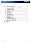
The integral is calculated using a trapezoidal approximation.
As can be seen in Figure 3.7, the area associated with a trapezoid is
A - .5(Xi+i - Xi)(Yi^.l + Yi)
^i+l'^i+1
^i+l
^i+l'^i
Figure 3.7.
Trapezoidal Approximation
Once the calculations are coir^leted, the cort^uter stores the
processed data file on the mass storage media for later recall.
Due to
the restricted memory space, the program was developed so that all of
the X data (2048 points—1024 points per curve) is loaded and evaluated
while the y data is loaded, evaluated, and stored, 256 points at a time.
This computational process is described in more detail in Chapter 4.
In section 4.4, a sample experiment is performed with the human/machine
interaction documented.
This example was designed as a tutorial for use
of this program, MATH^ including computer pronpts and operator
responses.
For further details regarding this program, refer to:
1) Appendix
A, Program Listings. "MATH," and; 2) Appendix C, User's Manual. Chapter
3, "Mathematical Processing Package."
28
The operation of the system has now been defined at the conponent
level and at the subsystem level.
In Chapter 2, the needs of the
laboratory were examined to develop an effective data accjuisition
system.
At the most basic level, functional system elements, and system
components, were cJefined to answer those needs.
In this chapter, those
functional elements were networked together to define subsystems to
carry out the tasks noted earlier.
These subsystems were examined operation by operation.
In so doing,
the author has defined the capabilities of the subsystems in contrast to
the capabilities of the individual system conponents.
Table 3.1 gives
an overview of the comparison between the system conponent capabilities
and subsystem capabilities.
In Chapter 4, the operations of each subsystem will be examined more
closely by offering examples to provide as tutorials.
These tutorials
will include conputer pronqpts and correct operator responses.
Table 3.1. Conparison of Component and Subsystem Capabilities
Conponent
Number of
Record
Minimum
Name
Records
Length
Sample Time
B
HP 3537A
1
2 2
Nicolet 2090
8
2 2
Tek 7612D
2
HP 9111A
1
B
1
B
256
lE-1
2E+0
4096 3
1024
5E-7
5E-7
2
2048
1024
5E-9
5E-9
2
1
512
lE-4 4
lE-4 4
^ A represents conponent capabilities; B subsystem capabilities.
^ Software allows 4 curves to be accjuired but storage is in pairs.
3 Total storage of 4096 points is ecjually divided among traces.
* Measurements are in meters rather than seconds.
See section 5.3.1.
CHAPTER 4
SYSTEM TUTORIAL
4.1
Introduction
In the previous chapters, the functional structure of the data
acquisition system was analyzed.
In Chapter 2, the system was examined
at the component level by matching individual pieces of equipment to the
laboratory needs.
In Chapter 3, the system was examined at the
subsystem level and the interactive capabilities were defined.
To
supplement the subsystem level discussion, this chapter was written to
provide a tutorial on the subsystem activities.
For ease of
interpretation, except where specifically noted, the computer
recjuests and the operator input use these indicated fonts.
First, however, the point should be made that there is a single
program which takes care of interconnecting the subsystems.
This
program, Autost, allows the operator to choose from all of the system
capabilities.
When the operator powers up the system, Autost is
automatically loaded and run.
the subsystem to be used.
From this program, the operator chooses
When the program begins, the following
appears on the screen:
Enter the data in a MMDD format.
For excuiqple, March 5 is entered
0305.
After the operator enters the correct date,
0803
the computer will display:
Enter the time in an HHMMSS
format.
For exeuiple, 3 a.m. is entered
030000.
The operator enters an accurate time of day,
022828
29
30
and the software sets the time and date of the computer.
has then been initialized for operations.
The computer
Initializing the computer
time and date is important because these values are stored with the data
that is taken.
This serves to document exactly when the measurements
were taken.
Now, the operator is allowed to choose the operation to be
implemented.
The computer displays the message:
Press key for desired fxinction.
Kl = Choose eunong data-takers.
K2 = Process data.
K3 = Plot curves.
K4 = Plot I-V curve only.
K5 = Use graphics capabilities.
The operator chooses from among these options.
Based upon the option
chosen by the operator, the computer proceeds to poll the equipment on
the network to make sure the subsystem elements are available.
If the operator chooses to take data, the computer produces the
following list of equipment available for measurement:
Press key for desired ecjuipment.
Kl = Tektronix 7612D Digitizer
K2 = Nicolet Digital 0-scope
K3 = HP Multiplexer & Voltmeter
K4 = HP Graphics Tablet
The computer then branches to the proper portion of the program to
check the availability of the subsystem.
If the Tektronix 7 612D is
chosen, the operator is asked:
Do you want to use the 7612D as
a normal 0-scope or a one-shot
storage scope?
(NORM/SINGLE)
The computer first polls the network to see if the Tektronix 7 612D
Programmable Digitizer and the HP9895A Flexible Disk Drive are on-line.
Then, if the operator has chosen to use the 7612D as a single-shot
storage scope, the computer asks:
31
Do you want to us* th* aysten
iroltflMter to mak« additional
rttadln9s?
(Y/N)
If the operator chooses to use the system voltmeter, the software polls
the network to see if the HP3497A Data Accjuisition/Control Unit and the
HP3437A System Voltmeter are available, as well.
Once all of the conponents are found to be available, the software
loads and runs the desired prograun.
If the 7612D is used as single-shot
storage scope, the program, JJalZD. (discussed in Appendix C, Chapter 7 ) ,
is loaded and run; otherwise, the program, NORML (discussed in Appendix
C, Chapter 6), is loaded and run.
If the Nicolet Digital Oscilloscope is chosen, the program polls the
network to see if the Nicolet 2090-III Digital Oscilloscope and the
HP9895A Flexible Disk Drive are available.
Then, the program asks:
Do you want to use the system
voltmeter to make additioxial
readings?
(Y/N)
If so, the program polls the network to ascertain the availability of
the HP3497A Data Accjuisition/Control Unit and the HP3437A System
Voltmeter.
The program then loads and runs the program, NIC-85
(discussed in Appendix C, Chapter 8 ) .
If the operator chooses to make use of the system multiplexer and
system voltmeter, the program polls the system to see if the HP9895A
Flexible Disk Drive, the HP3497A Data Accjuisition/Control Unit, and the
HP3437A System Voltmeter are available.
Then, the program loads and
runs the program, HP-DAS (discussed in Appendix C, Chapter 9).
If the operator chooses to use the graphics tablet, the program
checks the network for the availability of the HP9895A Flexible Disk
Drive and the HP9111A Graphics Tablet.
runs the program,
TABLET
Then, the software loads and
(discussed in Appendix C, Chapter 10).
If the operator chooses to process a set of curves, then the
software polls the network for the availability of the HP9895A Flexible
Disk Drive.
Then, the software loads and runs the program, MMii.
If the operator chooses to plot a set of curves, then the software
polls the network for the availability of the HP9895A Flexible Disk
32
Drive and the HP7470A Plotter.
Then, the software loads and runs the
appropriate program—I-V for current versus voltage plots; ELQT for the
remainder of the plots.
All of the previously mentioned options are available to the
operator, however, the graphics subroutine is not operational.
Therefore, if the operator chooses to use the graphics capabilities,
the message appears:
This program is not operational.
Please choose another function.
In the following sections, the software controlling each of the
subsystems is described in a tutorial setting.
This is provided to
allow the operator a closer look at the interaction between human and
software.
4.2
Slow Measurement Subsystem Tutorial
When the operator chooses to use the slow measurement subsystem, the
program, HP-DAS^ is loaded and run.
First, the program displays the
message:
Initializing
,
then proceeds to set the default values for variables in the program and
initializes the data registers.
Then, the software asks:
How many channels are to be
monitored by voltmeter? (4 max.)
The operator enters the number of channels to be monitored,
2
The operator then responds to the request
Enter the channel nuxtiber and the
voltage range.
(.IV = 1, IV = 2, lOV = 3)
by entering the value
/
This is then followed by a request for the time sample information:
Enter the time between samples.
(There will automatically be a
2-second delay between groups
33
of xnaaaureaMnts.
Ssseconda.
N^mlnutes,
8«parattt nuaaber from
u n i t with a coama. [Ex. 30, S]
This is responded to with the value
45, S
which sets the sair^le rate to once every 45 seconds.
The software then
recjuests the operator to choose a time frame to sanqple over:
Enter the total tine over which
to take samples.
(Max. 192 s)
(Separate nuxnber from unit with
a conma.)
The operator chooses to sanple over the maximum sanple period and enters
192, S
Given this information, the software calculates the number of samples to
be taken.
has begun.
Then, the software notifies the operator that the operation
The measurement is taken in two (2) pieces.
software takes a measurement.
First, the
Then, the coicqputer awaits the designated
sample time before taking another measurement.
Thus, the following
messages are repeated until the operation is completed:
Taking data
,
and
Waiting
When the software has completed the data accjuisition, it sets off a
two-tone alarm which sounds until the operator responds to the following
prompt:
The data Is stored.
Press Kl to continue program
When the operator presses the Kl key, the alarm halts and the program
proceeds to the data storage phase.
First, the program asks:
Nhere do you want to store these
curves?
(DISKOO/DISKOl/TAPE)
This is responded to with
DISKOO
The disk is preferred since it is much cjuicker than the tape drive on
the HP85.
The computer then begins the storage process.
This is done
34
by notifying the operator that:
Thara are 2 curvias.
and then requesting the operator to:
Enter tha nasM for curve 1.
This is entered as:
DASTST
The software then proceeds with the actual storage cycle.
The program
first creates a file on the disk, and then stores the data.
During the
storage cycle, the software displays:
Storing data In DASTST.
After completing the storage process, the software cjueries:
Do you want to take another set
of data?
(Y/M)
If the operator wishes to take another set of measurements, then the
entry is made:
Y
and the software displays the message:
Re-lnltlallslng
The software then resets the default values, re-initializes the data
registers, and returns to the segment of the program described in the
beginning of this section where the operator was asked to enter the
number of channels to be monitored.
If the operator does not wish to take another set of curves, then
the entry is made:
N
and the program displays the message:
MISSION CONTROL
will now resume control.
At this point, the software loads and runs the program, Autost
(described in the previous section).
4.3
Intermediate Measurement Subsystem Tutorial
When the operator chooses to use the intermediate measurement
subsystem, the program, NIC-SS,, is loaded and run.
First, the program
35
displays the message:
Zaltialisiag
,
then proceeds to set the default values for variables in the program
and to initialize the data registers.
Since the intermediate
measurement subsystem was designed to make auxiliary voltage
measurements, if desired, the software asks:
Do you want to use the system
•oltmatar to make additional
meaauramants?
(Y/N)
If the operator chooses to use the auxiliary system, then the entry is
made:
Y
which brings about the following interchange:
How many channels are to be
monitored by voltmeter?
(4 max.)
2
;
Enter the channel number and the
•oltaga range.
00,2
;
Enter the channel number and the
voltage range.
01,2
When the operator responds:
N
to the proir^t for the system voltmeter, or the entries for use of the
system voltmeter are completed, the program proitpts:
Set up Nicolet and take
measurement.
When you have the curve you
wish to store, press CONTINUE.
After the operator accjuires a desirable curve, the computer is notified.
The program then warns the operator of the restrictions associated with
this software:
The processing package can
handle no mora than 1024 data
36
pax cunra.
Thazefora, only 1024
of tha data will ba uaad by tha
procasalag program.
Thla la
equivalent to using Ql to Q4.
To view what will ba procaasad,
turn the MEMORY switch to Q3.
To resume:
restore MEMORY to ALL
and press CCmTINUE.
When the computer is notified that a good measurement had been taken,
the software proceeds to load the normalization factors and the curve
data from the Nicolet.
Then, the software displays the available
options:
Kl s Store all data.
K2 B Process new set.
K3 - Finished.
If the operator first seeks to store the data accjuired, the software
pronqpts the operator for the name and storage location for the file:
What name do you want for the
storage file?
NICTST
;
Nhere do you want the curves
stored?
(DISKOO/DISKOl/TAPE)
DISKOO
In order to display the capabilities of the system, four (4) curves are
accjuired before notifying the computer that the transfer is ready.
Since there were more than two (2) curves to be transferred, the
software notifies the operator:
There are 4 curves but
the processing package can only
handle two curves per run,
unless both curves are the same
type. I.e. both current.
In that
case, only 1 curve per file.
Nhlch two curves do you want
paired together?
(1-4)
37
(taparate eurvaa by a eoana:
1,4)
(To atora alngla curvaa, enter
number twlca:
1,1)
The curves that are accjuired reflect two (2) pairs of readings.
Thus,
the operator enters the first pair:
for the first storage cycle.
The software displays the message:
Storing data In NICTST
At that time, the software creates space for the file and stores the
data.
Since there are more than one (1) pair of readings the conqputer
asks:
Do you want to store another
set of these curves?
(Y/N)
Again, the set of four (4) curves are taken to reflect two (2) distinct
pairs of readings.
Therefore, the operator enters:
Y
At that point, the software again asks for a pair to be stored together.
To this recjuest, the operator responds:
3,4
Whereupon, the computer proceeds to store the other pair of curves.
After con^leting the storage process, since the auxiliary voltage system
has been used, the software asks:
What name do you want for the
auxiliary file?
The operator responds to this cjuery:
NICAUX
The computer then begins storing the auxiliary data:
Storing data In NICAUX
This storage process is not in a standard format.
pointed out in the previous chapters.
This difference was
Therefore, once the rest of the
operations are conpleted, the software loads and runs the program,
VMAuy.
After conqpleting this storage process, the software asks:
Have you stored the present set
of curves?
(Y/N)
38
Of course, the curves have been stored.
Thus, the operator enters:
Y
Having con^leted the storage process, the conqputer asks for further
data:
Do you wlah to digitize another
aat of curvaa?
(Y/N)
If the operator chooses to take another set of curves, then the entry is
made:
Y
Whereupon, the software returns to the accjuisition beginning with the
initialization.
If, on the other hand, the operator is finished with the acc[uisition
process, then the entry is made:
N
At that point, the software will load and run one of two programs.
For
the case of no auxiliary voltage measurements, the software loads and
runs the program, Autost.
In that case, the software displays:
MISSION CONTROL
will now resuzDe control.
For the case where auxiliary measurements are taken, the software
loads and runs the program, iZMAUX.
This program is designed to reformat
the auxiliary file data into a form consistent with the rest of the
files.
After loading JZMAUX, the program proceeds by displaying:
Initializing
The program first asks for the name of the auxiliary voltage file
and its storage location:
What Is name of the axixlllary
voltage file associated with
NICTST?
NICAUX
Where Is NICAUX stored?
DISKOO
With this information, the program then begins reading in the file.
software then asks for the name for the auxiliary files—one at a
The
39
time:
Reading
There are 2 c u r v e s .
Enter t h e neune f o r curve 1.
AUXFNI
;
Enter the name for cuzrve 2.
AUXFN2
The program then stores each of the curves in a separate file under the
name given above.
However, before storing the files, the software asks
for the conversion processes associated with each curve.
If, for
example, there is only one conversion process (the first curve).
The
interaction is:
Storing AUXFIN
Is an attenuator, current
transformer, thermocouple, etc.,
being used?
(Y/N)
Y
;
What is the conversion process?
(For exeuiple, a 6dB attenuator
converts a 2-volt input at the
source to a 1-volt input at the
scope.
So conversion is 2V to
IV - entered 2V, IV.
Enter
using scientific notation and
include units - A, V, K, etc.)
2A, IV
As the curves are stored, their data is scaled to reflect the conversion
process.
Thus, the stored data reflects the quantity of interest.
After reformatting the data files and storing them, the software then
asks if there are more curves which were stored during the measurement
process:
Did you store any curves other
than TRNTST?
(Y/N)
If more curves were stored, then the program will return to the
initialization process in VMAUX.
Otherwise, the software will notify
40
the operator that Autost is being loaded and run:
MISSION CONTROL
will now resume control.
A..J
Fast Measurement Subayatem Tutorial
When the operator chooses to use the intermediate measurement
subsystem, the program, 76120, is loaded and run.
First, the program
displays the message:
Initializing
then proceeds to set the default values for variables in the program and
initializes the data registers.
The program then asks for the number of
curves to be digitized:
How many curves will be
digitized and stored?
(1-2)
For this tutorial, two (2) curves are chosen for digitizing.
Thus, the
entry is made:
2
The program next asks if there will be a repetitive set of measurements.
This program was designed for measurements that will all be made with
exactly the same instrument settings.
For this case, only one set of
measurements is taken:
Will this ba a repetitive set
of measurements at the same
settings?
(Y/N)
N
Since the fast measurement subsystem was designed to make auxiliary
voltage measurements, if desired, the software asks:
Do you want to use the system
voltmeter to make additional
maasurtfoents?
(Y/N)
If the operator chooses to use the auxiliary system, then the entry is
made:
Y
41
which brings about the following exchange:
Raw aany ehannala aza to ba
monltocad by voltaatar?
(4 max.)
2
f
Intar tha channel number and tha
(.IV - I, IV « 2, lOV = 3)
0a,2
Enter tha channel number and tha
•oltaga ranga.
(.IV • I, IV « 2, lOV = 3)
01,2
When the operator responds:
N
to the pron9>t for the system voltmeter, or the entries for use of the
system voltmeter are conqpleted, the program pronqpts:
Jkdjuat tha POSITION knob on
plug-In A to aat zero line.
Adjuat tha POSITION knob on
plug-In B to sat zero line.
This pronqpt is to get the operator to adjust the baseline on the
individual plug-ins so that the sweeps appear in the correct position on
the screen.
After the baseline is established for the plug-ins, the
program pronqpts:
Enter tha measurement settings
on tha front panel of the 7612D.
Whan entry Is cooqplate, press
the REMOTE button on the front
panel (lower center).
This program was developed to allow the operator to adjust instriament
settings at the front panel.
entry easier.
This reduces the setup time, and makes the
After the operator is finished with the measurement
setup, the computer is notified that the system is prepared, and the
computer loads all of the measurement settings and reprints them on the
42
screen:
Vor tba aalnfraoaa:
CLK INT
wm oiT
NRz orr
RQS ON
REM orr
ror tlflM base A:
EEC 1,1024
SBPT 0,lE-6
NODE PRE,104
LTC LETT
SRC INT
SLO POS
HTR orr
CPL AC
LEV 0
ror time baaa B:
REC 1,1024
SBPT 0,lE-6
MODE PRE,104
LTC LETT
SRC INT
SLO POS
HTR orr
CPL AC
LEV 0
Once the software has completed displaying the settings, the operator is
asked:
Are all of the settings correct?
(Y/N)
If the settings are incorrect, the operator enters:
A^
and the progrzmv returns to the setup routine above. Otherwise, the
43
program proceada to aak if there are any conversion processes:
la aa attwkuator, eurzant
tcaaaforBMr, or currant-aana 1 ng
raalator balng uaad?
(Y/N)
(Do not conaldar xlO probaa.)
Y
;
r
Nblch of tha plug-laa uaaa one
of thaaa davlcaa?
(A/B/C)
(C la aqulvalant to A and B.)
A
Nhat la tha convaralon process
for plug-In A?
2A, IV
These values are used to calculate the true units from the voltages
which appear at the scope.
After the conversion factors are entered,
the program proceeds with the data accjuisition process by arming the
time bases.
If only one (1) curve is being taken, the program asks:
Which time base la to ba armed?
(A/B)
A
The program then arms the designated time base, and awaits the
accjuisition of a good measurement.
The program then notifies the
operator to take a measurement:
Time base A armed.
Now, almply take measurement.
Whan tha curve appears on the
monitor, press CONTINUE.
Once the computer finds an accjuisition has been made, it cjueries the
operator:
Do you wish to keep this data?
(Y/N)
If the operator decides not to keep the data, the computer will prompt:
Do you wlah to change tha
aattlnga?
(Y/N)
If the settings need to be changed, the program will return to the
44
settings area described earlier in this section.
Otherwise, the program
will keep the same settings and attexc^t to take another sweep by arming
the time base(s) again.
Once the program is notified that the operator
wishes the curve to be stored, the software will ask where to store the
file and under what name:
Whara do you want tha curves
stored?
(DISKOO/DISKOl/TAPE)
DISKOO
;
What name do you want for tha
storage file?
TRNTST
Once the program has a file name and storage location, the program will
proceed to store the data.
Until the data storage cycle is conqpleted,
the software will display the message:
Storing data In TRNTST
Once the program has completed storing the normal curve data, the
program will prompt for the neuae of the auxiliary voltage data:
What name do you want for the
auxiliary file?
TRNAUX
This is stored temporarily in the same way as the auxiliary voltage
measurements from the intermediate measurement subsystem.
will be called later.
Thus, ^Qi^JX
Once the program has a name for the auxiliary
file, the software proceeds to store:
Storing data In TRNAUX
Data Is stored.
After coxrrpleting the auxiliary storage cycle, the program will ask:
Do you want to take another
set of data?
(Y/N)
If the operator chooses to take another set of curves, then the entry is
made:
Y
Whereupon, the software returns to the accjuisition beginning with the
initialization.
If, on the other hand, the operator is finished with
45
the accjuisition process, then the entry is:
N
At that point, the software will load and run one of two programs. For
the case of no auxiliary voltage measurements, the software will load
and run the program, Autost.
in that case, the software displays:
MISSION CONTROL
will now raauma control.
For the case where auxiliary measurements are taken, the software loads
and runs the program, VMAUX. This program was designed to reformat the
auxiliary file data into a form consistent with the rest of the files.
After loading
VMAUX^
the program proceeds by displaying:
Initializing
The program first asks for the name of the auxiliary voltage file and
its storage location:
What la name of tha auxiliary
voltage file aasodated with
TRNTST?
TRNAUX
;
Where la TRNAUX stored?
DISKOO
With this information, the program then begins reading the file. The
software then asks for the name for the auxiliary files—one at a time:
Reading
There are 2 c u r v e s .
Enter t h e name f o r curve 1.
AUXFNA
;
Enter the name for curve 2.
AUXFNB
The program then stores each of the curves in a separate file under the
name given above. However, before storing the files the software asks
for the conversion processes associated with each curve.
In this case,
there is only one conversion process, that being for the first curve.
The interaction is:
Storing AUXFNA
Is an attenuator, current
46
transformer, thermocouple, etc.,
being used?
(Y/N)
Y
What is the conversion process?
(For example, a 6dB attenuator
converts a 2-volt input at the
source to a 1-volt input at the
scope.
So conversion is 2V to
IV - entered 2V, IV.
Enter
using scientific notation and
include units - A, V, K, etc.)
2A, IV
As the curves are stored, their data is scaled to reflect the conversion
process.
Thus, the stored data reflects the cjuantity of interest.
After reformatting the data files and storing them, the software then
asks if there are more curves which were stored during the measurement
process:
Did you store any curves other
than TPNTST?
(Y/N)
If there are more curves stored, then the program returns to the
initialization process in VMAUX.
Otherwise, the software notifies the
operator that Autost is being loaded and run:
MISSION CONTROL
will now resume control.
4.5
Very Fast Measurement Subsystem
Tutorial (Hand Entry)
When the operator chooses to use the very fast measurement
subsystem, the program, TABLET^ is loaded and run.
First, the program
displays the message:
Initializing
,
then proceeds to set the default values for variables in the program and
initializes the data registers.
The program then makes a hardcopy on
the printer of the functions assigned to the softkeys on the graphics
47
tablet:
Softkay Aaalgnaanta
1
END
End of curve.
Digitize to
atart naxt curve.
2
STORE
Tranafar curves to tape or
dlak.
3
NEW SET
Reinitialize and process new
set of curves.
4
riNISHED
rlnlahad with this program.
5
DEVICE DATA
Print out device data.
€-16
Not used.
After notifying the operator of the options available on the graphics
tablet, the software then proceeds with the digitization process by
recjuest ing:
How many curves will be entered? (1/2)
To this the operator responds:
1
The program then prepares to carry out the digitization process. First,
the boundaries of the trace to be entered have to be defined.
As
pointed out in previous chapters, this is done to allow the software to
condensate the data for rotational and translational offsets.
The
software recjuests the boundary inputs:
Please digitize the comers of
the graph grid In the following
order:
upper left, upper right,
lower left, and lower right.
From this information, the software calculates the compensating
constants for rerotating the plot.
Next, the software asks for the
information necessary to scale the newly defined active area to give
true units rather than the xy information which the computer actually
48
receives from the graphics tablet:
How mmaiftaoxlzontaldlvlalona
aca thara?
10
How nany vertical dlvlalona
8
What la tha value par horizontal
dlvlalon for curve 1?
(Enter value and unit, for
axaapla Sma » 5E-3,s.)
10, ms
;
Nhat la tha value par vertical
division for curve 1?
(Enter value and unit, for
example, 5A s 5,A.)
10, V
From these inputs, the software calculates the values that correspond to
the xy positions being digitized.
positive.
These values, however, will all be
The values cannot reflect a negative value, however, without
establishing a zero reference.
Therefore, the program asks for that
zero reference level:
ror curve 1:
on a scale of 0 to 8, what Is
the y-coordlnata for the origin?
(0 s lower left comer,
4 s left center, and
8 - upper left comer.)
After entering the relative position of the zero reference for curve 1:
4
the software notifies the operator to begin entering the curve:
Digitize curve 1.
The program then displays the options which can be selected by pressing
the available keys:
Kl • End of curve.
49
K2 s Stoza all data.
KB • Proeass naw aat.
X4 m rialshad.
K5 B Print davlca data.
These are in addition to the softkey assignments printed earlier.
This
is done so that the operator can select functions from either the
graphics tablet or the conqputer keyboard.
After the operator has
entered the curves, the conputer displays:
Digitization process Is
coaplata.
Please press key or
digitize softkay to continue.
From this point, the operator first chooses to store the data.
First, the software asks:
What name do you want for tha
atoraga file?
To this, the operator responds:
TABTST
Next, the software asks for the desired storage location:
Where do you want the curves
stored?
(DISKOO/DISKOl/TAPE)
Again, the operator chooses the disk because of its storage speed:
DISKOO
The program then proceeds to store the data and notifies the operator:
Storing data In TABTST
Data la stored.
When the program finishes storing the data, the operator is asked
whether or not another set of curves will be digitized.
First, however,
the program checks to see if the operator has stored the present curves:
Have you stored the present set
of curves?
(Y/N)
Then, the program asks if another set of curves will be digitized:
Do you wish to digitize another
set of curves?
(Y/N)
If the operator chooses to digitize another set of curves, the reply is
50
entered:
Y
and the program returns to the initialization process mentioned at the
beginning of this section.
run the program, Autost.
Otherwise, the program proceeds to load and
In that case, the software displays:
MISSION CONTROL
will now resume control.
On the other hand, if the operator chooses to print the device data,
then the program proceeds to enter and print the device data.
For the
device data discussion only, the conputer recjuests and the hardcopy
output sent to the thermal printer use the indicated fonts:
Enter manufacturer.
Manufacturer - UNITRODE
Enter device type.
Device type - BUX98
Enter mask type or other
applicable data.
Mask type or other applicable
data-NH LOT 5
Enter device number.
Device number - 037
Enter tenperature (RT or
degrees C)
Temperature -RTC
Enter SB type (N, A, B, or C.)
SB type - C
Enter forward base current.
Forward base current - .20 A
Enter nominal reverse base
current.
Reverse base current:
Nominal -1 A
Enter reverse base current
at SB.
ActualatSB-lA
51
Enter any additional coananta.
Comments:
After producing the printout of the device data, the software returns to
its former operation.
Thus, if the cievice data is produced during
digitization, then the software returns to the digitization process.
If, however, the operator digitizes a softkey which is not defined (6
through 16), then the program displays:
Thla aoftkay performs no
function.
Please choose
auothar.
A^
Hardcopy Output Subsystem Tutorial
When the operator chooses to get a hardcopy output of the curves
which have been accjuired, the progreun, £liQX, is loaded and run. First,
the program displays the message:
Initializing
Unless PLOT is the first program to be called after applying power to
the system, the name of the last file to be processed is passed to the
program.
Therefore, the software asks first:
Where la TABTST stored?
(TAPE/DISKOO/DISKOl)
To this the operator responds:
DISKOO
The program then displays the available options.
The program is written
so that first the operator chooses the desired plot; then, the software
loads the proper plot, if it exists:
Currently operating on TABTST
Plot V
Plot I
Plot P
Scale
New Set
Finished
Plot U
Based upon the operation chosen, the software loads the proper curve.
For any of the plot routines, the software asks:
Do you want this plot by Itself?
(Y/N)
If the operator wants a plot of the curve by itself, then the reply is
52
entered:
y
and the software sets up the plot so that only one (1) plot is placed on
a sheet of paper.
Otherwise, the operator enters:
N
and the software uses the default configuration which plots the curves
so that all four (4) can be plotted on a single piece of paper.
The
software then proceeds to ask for the axis titles which the operator
desires:
What title do you want for tha
time axis of this
current vs. time curve?
TIME
;
What title do you want for the
current axis of this
current vs. time curve?
Ic
The program also has the ability to plot the curve on either a grid or
an open graph.
Thus, the software cjueries the operator as to a
preference for grid or graph:
Do you want a grid or graph?
To this, the operator responds:
GRID
The program then is ready to plot the curve.
Thus, the software
notifies the operator:
Load plotter and press CONTINUE.
Once the plotter is loaded, the operator presses CONTINUE and the
program carries out the plotting.
In so doing, the software scans the
data file for maximum and minimum values to automatically scale the size
of the axis, and read the data into memory 1024 points at a time:
Scanning
Reading 1 of 1
The program then plots the curve.
After completing the plot, the
software asks the operator for the final cjuantities to complete the
53
plot:
Enter tha y-coozdiAata for tha
data and time.
Enter tha year - 1985
1985
Enter tha label for thla graph.
(Maxiaum length of 40 char.)
Collector Current
;
Enter tha y-coordlnata for tha
label of thla graph.
7
After completing a plot on a processed data file, the software asks:
Do you want a copy of tha
aacond-breakdown atatlstlcs?
If the operator does not wish to obtain a copy of the second-breakdown
characteristics, then the reply is entered:
N
and the program returns to the available options indicated earlier.
Otherwise, the operator enters the response:
Y
and the software displays:
Load plotter and press CONTINUE.
After the operator loads the plotter and presses CONTINUE, the software
proceeds to calculate the second-breakdown statistics.
This is done by
examining the voltage curve to find the time at which second-breakdown
began.
The values of each of the cjuantities are printed which
correspond to that time with the following statements:
The value for Instantaneous
voltage at 2nd-breakdown Is
765 V
The value for Instantaneous
current at 2nd-breakdo%m Is
3.38 A
54
The value for instantaneous
power at 2nd-breakdown is
2580 W
The value for instantaneous
energy at 2nd-breakdown is
166 uJ
2nd-breakdown occurs at
.722 us
The program then finds the time which corresponds to the voltage which
most closely approximates 10% of the second-breakdown voltage.
time is defined to be tQ.
This
Then, the values which corresponded to t^ are
printed for each of the cjuantities:
To is the time at 10% of the
2nd-breakdown voltage.
The value for instantaneous
voltage at To is 76.5V.
The value for instantaneous
current at To is 5.06 A.
The value for instantaneous
power at To is 387 W.
The value for instantaneous
energy at To is 33 uJ.
Next, the software calculates the time from tQ to second-breakdown, and
the change in energy from tQ to second-breakdown:
The time from To to
2nd-breakdown is .0839 us.
The change in energy from To
to 2nd-breakdown is 133 uJ.
After completing the printout of the second-breakdown characteristics,
the software then returns to the available options noted earlier.
If the operator chooses to do so, the software changes the scale of
the plots.
In so doing, the operator is allowed to control the size of
the plot:
Enter the scale factor for
plotting (less than 2.25.)
55
Once the operator is prepared to proceed to another set of curves,
the software prompts:
Nhat la tba naw f 11a nana?
To this the operator responds:
f
TRNTST
and the software begins the operations again at the initialization
process outlined in the beginning of this section.
When the operator is finished, the software loads and runs the
program, Autost;
MISSION CONTROL
will now raauma control.
The software package, £LQX, was developed to generate plots of
current, voltage, power, and energy. Another useful plot is one of the
current versus the voltage. Unfortunately, due to the limited memory
capacity of the HP85, this option could not be included in the program,
PLOT.
Instead, a second program, I-V, was developed.
The program, l-v, was developed specifically for plotting the
current versus voltage curve. The program operates in much the same way
as the program,
PLOT.
First, the program displays the message:
Initializing
Unless I-V is the first program to be called after applying power to the
system, the name of the last file to be processed is passed to the
program.
Therefore, the software asks first:
Where Is TABTST stored?
(TAPE/DISKOO/DISKOl)
To this the operator responds:
DISKOO
The program then displays the available options:
Currently operating on TABTST
I-V
Scale
New Set
Finished
The software then proceeds to ask for the axis titles which the
operator desires:
What title do you want for the
voltage axis of this
56
currant TS. voltage euzva?
V€e
;
What titla do you want for tha
currant axla of thla
currant va. voltage curve?
Ic
The program also has the ability to plot the curve on either a grid or
an open graph. Thus, the software cjueries the operator for a preference
of grid or graph:
Do you want a grid or graph?
To this, the operator responds:
GRID
The program then is ready to plot the curve. Thus, the software
notifies the operator:
Load plotter and press CONTINUE.
Once the plotter is loaded, the operator presses CONTINUE and the
program carries out the plotting.
In so doing, the software scans the
data file for maximiom and minimum values in both plots to automatically
scale the size of the axes, and read the data into memory 1024 points at
a time:
Scanning A
Scanning B
Reading 1 of 1
If the operator chooses to do so, the software will change the scale of
the plots. In so doing, the operator is allowed to control the size of
the plot:
Enter the scale factor for
plotting (lass than 2.25.)
Once the operator is prepared to proceed to another set of curves, the
software prompts:
What Is tha new file name?
To this the operator responds:
TRNTST
and the software begins operations again at the initialization process
outlined in the beginning of this section.
57
When the operator is finished, the software loads and runs the
program, AutflflL:
NI88I0II CONTROL
will now raauna control.
±J1—Mathematical
ProceggJng Subsystem Tutorial
When the operator chooses to process data accjuired in the earlier
processes, the program, MAIH, is loaded and run.
First, the program
displays the message:
Initializing
Unless M&Xli is the first program to be called after applying power to
the system, the name of the last file to be processed is passed to the
program.
Therefore, the software asks first:
Where Is TABTST stored?
(TAPE/DISKOO/DISKOl)
To this the operator responds:
DISKOO
The program then reads in the maximum and minimum time for each of the
curves to be processed.
These values are used to define the time frame
over which the power (product) and energy (product time-integral) will
be evaluated.
This is denoted by the message:
Sorting
Having calculated the time frame over which the curves will be
evaluated, the program proceeds to read the applicable time values.
These time values are then sorted together to produce a set of common
times.
This portion of the program is announced by the display:
Initial read and sort
Having developed a full set of time values by sorting together all the
available times and discarding any redundant times, the program then
creates a file of sufficient size to store the file which is to be
processed.
The software displays:
Creating file space
The program then carries out the processing.
The first step in the
processing is the interpolation of the curves.
of a finite number of sanples.
Each curve is composed
The ecjuations for each of these lines
58
are calculated.
values.
These lines are then evaluated for each of the time
This is performed in a three-part process of reading,
evaluating, and storing.
During the interpolation of the voltage curve,
the conqputer displays:
Procaaa 1 of 4
Reading 1 of 1
Procaaa 1 of 4
Working 1 of 1
Procaaa 1 of 4
Storing 1 of 1
Next, the current curve is interpolated, evaluated, and stored.
During
this process, the computer displays:
Process 2 of 4
Reading 1 of 1
Procaaa 2 of 4
Working 1 of 1
Procaaa 2 of 4
Storing 1 of 1
After finishing the interpolations, a power curve is calculated.
This
is done by performing a point-by-point multiplication of the voltage and
the current curves.
During this process, the conqputer displays:
Process 3 of 4
Reading 1 of 1
Process 3 of 4
Worklxig 1 of 1
Process 3 of 4
Storing 1 of 1
After coir^leting the power curve, the software evaluates the energy
curve.
This is done by performing a time integral of the power
(product) curve.
This is evaluated using a trapezoidal approximation
discussed in the previous chapter.
displays:
Process 4 of 4
Reading 1 of 1
Procaaa 4 of 4
During this process, the computer
59
WoBkiag 1 of 1
Procaaa 4 of 4
Storing 1 of 1
After the processing is conpleted, the software asks for a processed
data file name.
This allows the operator to keep both an unprocessed
and a processed data file.
Should the operator choose to store under
the same name, then the program will take care of purging the old file.
In order to store the processed data file, the progreun asks:
What name do you want for the
procaaaad data file?
After the processing is completed, and the processed file has been
stored, the computer displays:
The processing Is finished.
Then, the program is ready to process another file.
The program
displays:
Would you like to process
another set of curves?
(Y/N)
If the operator chooses to process another set of curves, then the
operator replies:
Y
Then, the software returns to the initialization described at the
beginning of this section.
Otherwise, the software loads and runs the
program, Autost:
MISSION CONTROL
will now resxune control.
4.8
Summarv
Each of these tutorials was developed as an example of correct
system operation.
They do not reflect, however, the extensive error
handling capabilities of the system software.
Instead, the operator is
presented with the pron^ts generated by the computer and realistic
operator responses.
In addition to the tutorials presented in this chapter, the operator
may refer to Appendix C for a complete user's manual.
Also, there are
60
program listings contained in ^E^>endix A if the reader is interested in
the exact manner in which the operations are performed.
CHAPTER 5
SYSTEM ACCURACY
5.1 Intrf>Hnr!l-^r»n
In the previous chapters, the development of a data accjuisition and
conditioning system was discussed from conceptualization to
inplementation.
The discussion of the system would not be complete,
however, without a discussion of system accuracy. System accuracy will
be considered in two (2) distinct areas:
1) data accjuisition, and 2)
data conditioning.
For the data accjuisition discussion, system accuracy is considered
to be the difference between the bit accuracy claimed by the
manufacturer and the bit accuracy observed during measurements made with
the conponent.
To support this line of investigation, the various
errors associated with analog to digital conversion were identified and
their respective effects on the data analyzed.
For the data conditioning discussion, system accuracy is considered
to be the errors associated with the data processing.
This processing
includes both binary to decimal code conversions and multiplicative
scalar corrections.
In support of this investigation, the separate
numerical algorithms were analyzed.
5.2 Analysis of Accjuisition System Accuracy
To ascertain the accuracy of the system components, the inherent
errors associated with analog to digital (A/D) conversion were defined.
Each type of A/D conversion then was examined to identify the conversion
errors which were unicjue to a given form of A/D conversion.
After
identifying the pertinent errors for each type of A/D conversion, each
subsystem was examined to identify the respective conversion type,
thereby identifying the pertinent A/D errors.
Finally, measurements
were defined and performed to ascertain the system component accuracy.
61
62
5.2.1 Definitions of A/D Conversion Aecuraey
Each Of the subsystems has a conqponent which carries out some A/D
conversion.
Several different types of errors are associated with any
A/D conversion.
A/D conversion errors include cjuantizing error, gain
error, offset (zero) error, hysteresis error, non-linearity, and
differential non-linearity.
These errors are inherent in the A/D
conversions carried out by the HP System Voltmeter and the Nicolet
Digital Oscilloscope.
Quantizing error is the uncertainty associated with each digital
step. All analog values within a given range are represented by the same
digital code.
Therefore, there is a limited accuracy in the value of
the measurement. In most cases, the code is ecjuivalent to the midrange
value so that the uncertainty is ±1/2 the least significant bit (LSB).
Gain error is the difference between the actual input voltage and
the theoretical input voltage for a full-scale output code.
This
phenomena can be attributed to errors in reference voltage, ladder
resistance values, or anplifier gain.
Under these circumstances, some
bit(s) in an A/D converter (ADC) would recjuire a larger or smaller step
to set the bit(s).
Thus, the value associated with the output code is
not uniformly weighted.
Offset (zero) error is the recjuired mean value of input voltage to
set the output code to zero (0). This error corresponds to some DC
offset in the measurement which is due not to the desired channel;
rather, the output code reflects an artifact of the measurement setup.
This error, however, is removed using software.
Under software control,
a measurement is taken with the input grounded.
This provides a
non-zero trace which corresponds to the offset error.
The offset error
is averaged and removed from the actual measurement by numerical means.
Hysteresis error causes the voltage at which a code transition
occurs to be dependent upon the direction from which the transition is
approached. Thus, the thresholds associated with each range boundary are
dependent upon the direction from which the range is entered.
For
exanple, if the range to produce code IOII2 is from .01 to .02 mV, one
would expect the code to change from IOIO2 to IOII2 at .01 mV for an
increasing function and from IOII2 to IOIO2 at .01 mV for a decreasing
63
function.
If the coda changed from IOIO2 to IOII2 at .015 mV for an
increasing function and from IOII2 to IOIO2 at .005 mV for a decreasing
function, then one would know that there is a hysteresis error.
Non-linearity describes the cteviation of the analog values from a
straight line In a plot of the measured conversion relationship.
can be expressed by either of two (2) cjuantities:
1) integral
non-linearity, and 2) differential non-linearity.
The integral
This
non-linearity is the overall cieviation from a straight line transfer
function.
This will be referred to simply as non-linearity.
Differential non-linearity is any deviation of the measured "step"
from the ideal width.
Thus, the differential non-linearity is a measure
of the performance at the bit level while integral non-linearity
describes the overall behavior of the ADC.
Both types of non-linearity are used to cjualify the cjuantity of
monotonicity.
Monotonicity insures that an ADC will provide no
decreasing output code for an increasing input voltage.
In addition, to the errors associated with standard ADCs, there is
also the error associated with stuck bits.
This occurs when a bit is in
a particular state (1 or 0) and remains in that state despite the change
in input voltage.
Stuck bits are of particular interest in the
Tektronix Programmable Digitizer since it uses a different type of A/D
conversion process.
Where the HP System Voltmeter and Nicolet Digital
Oscilloscope use a successive approximation method for A/D conversion,
the Tektronix Programmable Digitizer (7612D) sweeps an electron beam
across a semiconductor target.
In this manner, the 7612D directly converts the position of the beam
on the target into a digital code.
into memory.
This digital value is then clocked
As such, the errors mentioned earlier do not pose a
problem to the 7612D.
Only the problem of stuck bits is significant.
5.2.2 Errora in Succeaaive-AppgQximatiQn
A/D Conversion
As noted earlier, the HP System Voltmeter and the Nicolet Digital
Oscilloscope are susceptible to several types of error.
Of the errors
mentioned in section 5.2.1, however, two (2) error types are not
64
significant:
1) quantizing error, and 2) offset (zero) error.
The
cjuantizing error is not significant because it is intrinsic to all A/D
conversions.
This uncertainty is ecjual to one (1) part in 2^ over the
full-scale reading value.
For example, an 8-bit ADC with a full-scale
reading of 10 volts will have a cjuantizing error of 39.06 mV.
This
corresponds to l/256th of the 10 V full-scale reading.
The offset error is also ignored in the following discussion because
the offset error is calibrated out of the measurement by taking a
baseline reading prior to the first measurement.
This data is then used
to evaluate an offset value which is removed from the actual data.
This
conditioning removes the offset error numerically to allow for both the
offset error in the ADC, and the theinnal drift and DC offset associated
with the plug-in(s).
Thus, there remain five (5) possible errors which can intact the
accuracy of the measurement:
1) gain error, 2) hysteresis error, 3)
non-linearity, 4) differential non-linearity, and 5) stuck bits.
In
order to evaluate the possible effect of these errors, a slow triangular
waveform was measured using each of the two (2) conponents.
From the
resulting data file, each of the errors was examined.
If there is a gain error, then a constant-slope waveform (such as a
triangular or saw-tooth wave) will develop a recurring pattern in the
individual changes from point to point.
For exan5>le, instead of having
a pattern of 2, 2, 2, 2, 2, 2 there will be a pattern of 2, 4, 3, 2, 4,
3.
The latter pattern indicates the bits are not equally weighted.
If there is a hysteresis error, then a constant-slope, symmetrical
waveform will not transition from value to value in an ecjuivalent manner
on opposite sides of the waveform.
This is consistent with the
description for hysteresis error given in section 5.2.1.
If there is a problem with non-linearity, the montonicity of the
signal will be destroyed.
As noted in section 5.2.1, a monotonic ADC
will never give decreasing values for an increasing voltage input.
By
examining the values measured for a triangular or saw-tooth wave, one
can find if the curve is truly monotonic.
If so, the linearity of the
component is within the bounds of 1 1/2 least significant bit (LSB).
65
Finally, if there are stuck bits, again the monotonicity of the
waveform will be destroyed.
However, stuck bits will effect the
monotonicity of the curve in a manner different from the non-linearity
errors.
Stuck bits can be characterized in one (1) of two (2) possible
patterns:
1) sporadic, and 2) continuous.
A sporadically stuck bit will be seen as isolated points where the
waveform Is no longer monotonic.
This will be easily detectable since
the values will not necessarily be consistent.
In fact, the error
associated with a sporadically stuck bit could also be explained as
unwanted noise on the signal channel.
However, if this noise does not
occur in all of the measurements, one could argue that the error is due
to the digitizer rather than the source.
Each continuously stuck bit will prevent one (1) in every 2^ codes
from being written for an n-bit ADC.
For d stuck bits, an n-bit ADC
will be able to generate 2 ^'^"^^ unicjue codes.
Thus, an 8-bit ADC will
be able to develop 128 possible codes instead of 256 codes if there is
one (1) stuck bit.
5.2.3 Errors in Direct Conversion A/D Processes
As noted at the end of section 5.2.1, the manner in which the
Tektronix Programmable Digitizer (7612D) accjuires digital information
removes the susceptability of the device to many of the errors mentioned
in section 5.2.1.
As such, the only anticipated error arises from a
problem with stuck bits. (Again, cjuantizing error and offset error are
either insignificant or correctable and are not discussed in the
following text.)
Examining the monotonicity of the accjuired waveform will provide the
information necessary to decide whether or not the device has stuck
bits.
As noted earlier, this could be a problem of a continuously stuck
bit or a sporadically stuck bit.
However, due to the fact that the
7612D does not have an intrinsic problem with differential nonlinearity, the determination as to whether or not there were stuck bits
proved rather sinqple.
One (1) last error which may occur in data accjuisition with the
7612D is the possibility of non-linearity in the sweep circuit.
This
66
will cause the beam to sweep across one (1) portion of the target more
quickly than another.
This will not effect monotonicity.
However, it
will appear as a non-linear error conparable to that noted for gain
error.
This non-linear sweep will manifest itself as a repetitive
pattern equivalent to that noted for gain error.
5.2.4 HP System Voltmeter Meaauremftnta
In accordance with the rationale set forth in section 5.2.2, a
triangular waveform was measured using the HP System Voltmeter.
The
waveform was a 4-volt triangular wave with a frecjuency of approximately
2 mHz (millihertz). The waveform was digitized approximately once every
3.168 s.
This data was then examined for any indications of the errors
set forth in section 5.2.2.
First, the data was examined for evidence of gain error.
This
type of error can be identified by a repetitive unecjual bit pattern with
a length greater than two (2) bits.
observed.
Therefore, the HP System Voltmeter is presumed to have no
appreciable gain error.
examined.
This type of pattern was not
Next, the monotonicity of the data was
Again, there was no indication of error.
Since the data was
monotonic, it can be inferred that linearity is within the constraints
of 1 1/2 least significant bit, and that there were no stuck bits during
the measurement.
Finally, the symmetry of the data was examined.
If a hysteresis
error existed, the symmetry of the data would be perturbed.
Again,
there was no indication of an error.
Therefore, the errors associated with the A/D conversion of the HP
System Voltmeter are within theoretical limits.
This indicates that the
HP System Voltmeter was operating at the accuracy claimed by the
manufacturer.
The 3 1/2 digit accuracy of the HP System Voltmeter
corresponds to a 12-bit accuracy.
5.2.5 Nicolet Digital Oscilloscope Measurements
Next, a triangular waveform was measured using the Nicolet Digital
Oscilloscope.
This measurement was patterned after the one performed
using the HP System Voltmeter.
In this case, the waveform was a 4-volt
67
triangular wave with a frequency of approximately 800 Hz.
This waveform
was digitized approximately once every .25 jls. This data was then
examined for any indications of the errors set forth in section 5.2.2.
First, the data was examined for evidence of gain error.
This type
of error can be identified by a repetitive unecjual bit pattern with a
length greater than two bits.
This type of pattern was not observed.
Therefore, the Nicolet Digital Oscilloscope is presumed to have no
appreciable gain error.
Next, the monotonicity of the data was examined.
was no indication of error.
Again, there
Since the data was monotonic, it can be
inferred that linearity is within the constraints of 1 1/2 least
significant bit, and that there were no stuck bits during the
measurement.
Finally, the symmetry of the data was examined.
If a hysteresis
error existed, the symmetry of the data would be perturbed.
Again,
there was no indication of an error.
Therefore, the errors associated with the A/D conversion of the
Nicolet Digital Oscilloscope are within theoretical limits.
This
indicates that the Nicolet Digital Oscilloscope was operating at the
accuracy claimed by the manufacturer.
The accuracy claimed by Nicolet
for this particular scope and plug-ins is 12 bits.
5.2.6 Tektronix Programmable Digitizer
Meaauremenhfl
Finally, a triangular waveform was measured using the Tektronix
Progrsunmable Digitizer.
This measurement was patterned after the
previously described measurements.
In this case, the waveform was a
4-volt triangular wave with a frecjuency of approximately 80 kHz.
waveform was digitized approximately once every 50 ns.
This
This data was
then examined for the errors described in section 5.2.3.
Unlike the previous tests, there are only two (2) anticipated error
types: 1) stuck bits, and 2) non-linear beam sweep.
These two (2)
errors will be indicated by a lack of monotonicity and a repetitive
unecjual bit pattern, respectively.
The non-linear beam sweep, should it
68
occur, would be conqparable In appearance to the gain error mentioned in
the previous sections.
First, the monotonicity of the waveform was exaunined.
For a
256-polnt measurement, there were four (4) points where the waveform was
non-nonotonlc.
Two (2) of those four (4) points were measured in the
same neighborhood (approximately the same value).
(4) in 256 sanples is ecjuivalent to one (1) in 64.
An error rate of four
Thus, for one (1) in
every 64 points, the accuracy is reduced to seven (7) bits.
For the
remaining 63 of every 64 points, the accuracy is eight (8) bits.
This
represents an average value of slightly less than eight (8) bits.
Therefore, the accuracy of the Tektronix Programmable Digitizer will be
taken to be seven (7) bits for worst case considerations.
Finally, the data was examined for evidence of a non-linear beam
sweep. There was no indication of a repetitive unecjual bit pattern such
as that described for a gain error in the standard A/D conversions.
Therefore, when the Tektronix Programmable Digitizer is operated at
a sanpling time of approximately 50 ns, the user can anticipate that the
accuracy of the instrument will be seven (7) bits.
5.2.7 HP Graphics Tablet Measurements
In the previous sections, the errors associated with the operation
of the HP Graphics Tablet have been ignored.
This is due to the fact
that establishing a benchmark for a hand-operated digitization device is
difficult. The HP Graphics Tablet has an elemental grid whose dimensions
are 12032 by 8710 units on a matrix which is 301 mm by 218 mm.
This
grid structure corresponds to a placement of one (1) element every .025
mm.
The manufacturer claims this grid can resolve pen placement to .1
mm.
The principle difficulty in validating the resolution of the HP
Graphics Tablet is that the resolution is greater than that obtainable
by a human.
Therefore, the accuracy of the HP Graphics Tablet is
presumed to be that given by the manufacturer.
For the described grid,
one (1) part in 12032 is slightly less than 14-bit accuracy so that
13-bit accuracy will be used for the HP Graphics Tablet.
However, there is a difficulty associated with the operation of the
HP Graphics Tablet.
This difficulty is inherent to the physics of the
69
digitization process.
The location of the pen on the platen is
evaluated using the gradient of the electric field.
As such, the
process Is very sensitive to any conductive materials on the platen.
Therefore, the user is warned to take care not to use any materials
which are electically conductive. This includes graphite pencil leads,
some eraseable pen inks, and films using a conductive emulsion.
Any of
these materials will degrade the resolution of the HP Graphics Tablet
significantly by interfering with the mechanism used in digitization.
Further discussion of this matter is contained in Appendix C.
5.3 Analysis of Data Conditioning Accuracy
In addition to errors associated with the accjuisition process, the
data stored by this system has uncertainties associated with data
processing.
These uncertainties can be described in terms of accuracy.
Accuracy is considered to be the difference between the actual value and
the estimated value, and is expressed either as a magnitude (e.g., ±1 V)
or as a fraction of the full-scale magnitude (e.g., .01 Vfg).
The cjuantities evaluated during the processing are voltage, current,
power, and energy.
The accuracies for voltage and current are set by
the system conponents used during the data accjuisition phase.
The bit
accuracies for the system components were derived in previous sections.
The accuracy associated with power is derived from the individual
accuracies for voltage and current.
The accuracy associated with the
energy calculation is derived from the accuracy of the power calculation
and the time resolution capabilities of the particular system con^onent.
In addition to the evaluation of the mentioned cjuantities, the data
processing selects the values at second-breakdown for voltage, current,
power, and energy.
These values are then rounded to three (3)
significant figures.
To completely describe the accuracy of the system,
the system conqponent time resolutions, computational algorithms, and
value selection algorithms are investigated.
5.3.1 System Time Resolution
Time resolution reflects the system's ability to resolve between two
(2) adjacent points in time.
The closer in time the points are; the
70
greater the resolution of the system.
This resolution is set by the
digitizing rate of the selected device.
The maximum resolution is
ecjuivalent to the minimum sample period.
The minimum sample period
varies from device to device.
For the con^^onents of this system the
minimtom sampling periods are:
1) 100 ms for the HP Data Accjuisition/
Control Unit; 2) 500 ns for the Nicolet Digital Oscilloscope; 3) 5 ns
for the Tektronix Programmable Digitizer, and; 4) .1 mm for the HP
Graphics Tablet.
Of course, the resolution of the HP Graphics Tablet is given in
millimeters rather than some derivative of seconds since it is an x-y
format device.
This length resolution can be related to an ecjuivalent
maximum time resolution in the following manner.
For a standard oscilloscope, the grid format is 10 mm per division.
Most modern oscilloscope cameras produce a 1:1 reproduction of the
oscilloscope trace.
Thus, the resolution of the HP Graphics Tablet
corresponds to .01 division.
For data stored at 1 ns/division, the HP
Graphics Tablet resolution is 10 ps.
For exan^le, data cjuoted in
Chapter 4 was digitized using the HP Graphics Tablet.
Hence, the
resolution of the time data being used for exan^le material is
approximately 10 ps.
In general, the time resolution of any system conqponent is ecjual to
the san5>le period, tg, with an associated error term of At.
The time
resolution associated with the HP System Voltmeter is set by the timing
of the HP-85 Computer.
resolution of 1 ms.
computer of 1 ms.
The computer timing command, WAIT, has a
This yields a worst case resolution for the
In addition, the algorithm controlling the HP System
Voltmeter includes a wait state of .5 s to allow the voltage being
measured to settle.
This yields a worst case error term of 1 ms in .5s
which corresponds to one (1) part in 500.
For the more general case,
there will be a programmed delay chosen by the user which will add to
the . 5 s .
Therefore, the error term is one (1) part in (500 + tg) where
tg is expressed in milliseconds.
According to the manufacturer, the error term associated with the
Nicolet Digital Oscilloscope is .01% of the sample period.
an error term of one (1) part in 10000 of tg.
This yields
71
According to the manufacturer, the error term associated with the
Tektronix Programmable Digitizer is .0035% of the time base frecjuency,
200 MHz.
This yields an error term of .175 ps.
This error term is the
same for all sanple period settings because they are all based on the
same single frecjuency clock.
The time resolution associated with the HP Graphics Tablet is in
terms of the total time; however, the total time is dependent upon the
physical size of the data being digitized.
Since the digitized time
data is not necessarily evenly spaced as in the other devices, the HP
Graphics Tablet's time resolution can be expressed in terms of the
accuracy associated with the physical digitization process.
The HP
Graphics Tablet has error terms of one (1) part in 12032 and one (1)
part in 8710 for a digitizing area that is 301 mm by 218 mm,
respectively.
area.
The associated error terms are subsets of this digitizing
Thus, for an oscilloscope trace captured on film with a standard
format of ten (10) divisions by eight (8) divisions with 1 cm per
division, the error terms are approximately one (1) part in 4000 of the
full-scale magnitude in the x direction and one (1) part in 3200 of the
full-scale magnitude in the y direction.
data corresponds to the x direction.
In conventional use, the time
Therefore, the error term is one
(1) part in 4000 of the total time for a standard oscilloscope trace.
In general, the error term is given by
At = ttot<12032 Xtot / 301)-1
where t^ot ^^ ^*^® total time and X^ot ^^ ^*^® total length of the data
set along its x axis in millimeters.
5..^.2 Computational Accuracy
The steps involved in converting raw voltage and current data to
conqpletely processed energy data are:
1) scalar multiplication for
conversion from binary format to decimal format; 2) multiplication of
voltage and current to calculate instantaneous power, and; 3) time
integration of instantaneous power curve to generate energy data.
The voltage and current data can be defined in the following manner:
Vmb - Vb ± 1
72
and
Inib " lb ± 1^mb ^'^^ -^mb i^ep^cesent the estimated data values.
V^ and Ij^ represent
the actual data values.
To produce a decimal value for each of these cjuantities, the binary
numbers are multiplied by appropriate scalar values such that
V„ - AV(Vb ± 1)
- V ± AV
and
I^ - A l d b ± 1)
- I ± Al
where
AV = Vfg (2-^^),
AI - Ifg (2-™) .
Vjn and Ijn represent the estimated data values.
actual data values.
data values.
V and I represent the
AV and Al represent the estimated accuracies of the
Vfg and Ifg are the respective full-scale values which can
be measured by the system conponents.
In general, n and m represent bit
accuracies of the respective system conqponents.
However, for this
system, the two (2) bit accuracies are ecjuivalent, i.e., m - n, since
the system is designed to take two (2) simultaneous measurements using a
single system component.
For this data acquisition system, the values for voltage and current
have errors of:
1) one (1) part in -4096 of the full-scale magnitude
using the HP System Voltmeter; 2) one (1) part in 4096 of the full-scale
magnitude using the Nicolet Digital Oscilloscope, and; 3) one (1) part
in 128 of the full-scale magnitude using the Tektronix Programmable
Digitizer.
The error term associated with the HP Graphics Tablet is also in
terms of the full-scale magnitude; however, the full-scale is dependent
upon the data being digitized.
The HP Graphics Tablet has error terms
of one (1) part in 12032 and one (1) part in 8710 for data that is 301
mm by 218 mm, respectively.
this active digitizing area.
The associated error terms are subsets of
Thus, for an oscilloscope trace captured
on film with a standard format of ten (10) divisions by eight (8)
73
divisions with 1 cm per division, the error terms are approximately one
(1) part in 4000 of the full-scale magnitude in the x direction (total
time in most cases) and one (1) part in 3200 of the full-scale magnitude
in the y direction.
The instantaneous power is calculated by multiplying the voltage and
current waveforms and can be described as
P„ - P + AP
- V« Im
- (V ± AV) (I ± Al)
- VI ± VAI ± lAV ± AVAI.
Substituting in the values for Av and Al,
P,n - VI ± V d f g 2-") ± I (Vfg 2-n) ± (Vfg 2"'^) (Ifg 2"") .
Thus, the error term for the instantaneous power can be described as
AP - V d f g 2-'^) + K V f g 2-n) + (Vfg 2-n)(i£g 2-'^).
The worst case error occurs for V - Vfg and I = Ifs*
This yields a
worse case error of
AP - Vfg (Ifg 2-'^) + Ifg (Vfg 2"^) + (Vfg 2"'^) (Ifg 2 "^)
= Vfg Ifg (2-'^ + 2-^
+ 2-2n)
- Vfg If3(2l-'^ + 2-2n).
Since the second term is approximately the scjuare of the first term, the
second term in this ecjuation is considered to be insignificant so that
the error term becomes
AP - Vfg Ifg (21-^)
= Pmax (2l-n).
where Pmax ^^ ^^® maximum power.
For this data accjuisition system, the values for power have errors
of:
1) one (1) part in 2048 of Pmax using the HP System Voltmeter; 2)
one (1) part in 2048 of P^ax using the Nicolet Digital Oscilloscope,
and; 3) one (1) part in 64 of P^ax using the Tektronix Programmable
Digitizer.
These error terms represent twice that of their respective
voltage and current error terms.
The corresponding error term for the
HP Graphics Tablet is one (1) part in 1600 of PmaxThe energy is calculated by summing over the areas described by the
ecjuation
A - .5(Xi+i - Xi)(Yi+i + Yi)
74
which was derived in section 3.4.
For data taken using the HP Graphics
Tablet, the area is given as
^td+1 " Ai+i ± AAi+i
- .5(ti+i ± At - ti ± At)(Pi+i ± AP - Pi ± AP)
- •5(ti+i - ti ± 2At)(Pi+i - Pi ± 2AP)
- -SCti+i - ti)(Pi+i - Pi) ± At(Pi+i - Pi) ±
AP(ti+i - ti) ± 2AtAP.
As was noted earlier, the term 2AtAP represents a second-order error and
can be disregarded.
Thus, the ecjuation becomes
Ami+i - .5(ti+i - ti) (Pi+i - Pi) ± At(Pi+i - Pi)
± AP(ti+i - ti).
The energy is a sum over this ecjuation for all i.
So the energy is
represented as
E„| » E ± A E
= I(.5(ti+i - ti) (Pi+i - Pi) ± At(Pi+i - Pi) ± AP(ti+i - ti))
- S(.5(ti+i - ti)(Pi+i - Pi)) ±
S(At(Pi+i - Pi) + AP(ti+i - ti))
so that
AE - Z(At(Pi+i - Pi) + AP(ti+i - ti)).
This can be represented as two (2) separate sums
AE = I(At(Pi+i - Pi)) + X(AP(ti+i - ti)).
Since At and AP are constants, the expression can be rewritten
AE = AtI(Pi+i - Pi) + APZ(ti+i - ti) .
The first sum reduces to P^ - Pir and the second sum reduces to t^ ti.
The initial values for time and power, ti and Pj, respectively, are
zero (0). Therefore, the error for the energy calculation reduces to
AE = tmAP + PmAt.
The worst case error occurs for Pjjj = Pmax*
represented earlier as t^of>
^^m ^^ *^^® total time
^^^^ yields a worse case error term
AE = ttotAP + PmaxAt.
Substituting in values for AP,
AE - ttotPmax (Zl-'^) + PmaxAt.
The error term for time. At, can be represented in terms of the total
time, t^ot' ^3 '^^^tot-
Thus, the ecjuation becomes
AE - ttotPmax (2^'"") + Pmax^^ttot
75
- ttotPmax(2l-« + k)
- Emax(2^"'' + k) .
The error terms for time are:
1) one (1) part in (500 + tg) in ms
using the HP System Voltmeter; 2) one (1) part in 10000 of tg using the
Nicolet Digital Oscilloscope; 3) .175 ps using the Tektronix
Programmable Digitizer, and; 4) one (1) part in 4000 of ttot ^^^ ^
standard oscilloscope trace using the HP Graphics Tablet.
Expressing
these values in terms of the total time, ttof the error terms for time
are:
1) one (1) part in (500 + tg)m of ttot using the HP System
Voltmeter; 2) one (1) part in 10000m of ttot using the Nicolet Digital
Oscilloscope; 3) one (1) part in 28571m of ttot using the Tektronix
Progrzunmable Digitizer, and; 4) one (1) part in 4000 of ttot ^°^
^
standard oscilloscope trace using the HP Graphics Tablet for m san^les.
The largest error terms occur for the smallest sautple sets.
For the HP System Voltmeter, the user can select the number of
samples, m.
Typically, more than 100 measurements will be taken.
Using
this to bound the ecjuation, the worst case error term occurs when the
sanple period, tg, is chosen as zero (0). For tg = 0, the error term is
one (1) part in 50000 of ttotHowever, for considerations of energy, a useful cjuantity is the
minimum m which produces a negligible value for k. Presuming that k is
negligible for any 2^"^^ ^ 10k, k is insignificant any time more than 40
samples are accjuired using the HP System Voltmeter.
Therefore, the user
needs to take a minimum of 40 samples when using the HP System
Voltmeter.
This yields an error term for time of one (1) part in 20000
of ttotFor the Nicolet Digital Oscilloscope and the Tektronix Programmable
Digitizer, the minimum sample sets are 2048 data and 512 data,
respectively.
The error terms for time are:
1) one (1) part in 20.5
million of ttot using the Nicolet Digital Oscilloscope, and; 2) one (1)
part in 14.6 million of ttot using the Tektronix Programmable Digitizer.
The error terms for power are:
1) one (1) part in 2048 of Pmax
using the HP System Voltmeter; 2) one (1) part in 2048 of Pmax using the
Nicolet Digital Oscilloscope; 3) one (1) part in 64 of Pmax using the
Tektronix Programmable Digitizer, and; 4) one (1) part in 1600 of Pmax
76
for the HP Graphics Tablet.
Comparing the relative magnitudes of the
error terms, k is insignificant for the HP System Voltmeter, the Nicolet
Digital Oscilloscope, and the Tektronix Programmable Digitizer while k
and 2^'^
are comparable for the HP Graphics Tablet.
Therefore, the error terms for energy are:
1) one (1) part in 2048
of Ejnax using the HP System Voltmeter within the constraints outlined in
the previous paragraph; 2) one (1) part in 2048 of E j ^ ^ using the
Nicolet Digital Oscilloscope; 3) one (1) part in 64 of E^ax using the
Tektronix Programmable Digitizer, and; 4) one (1) part in 1143 of E^a^
for the HP Graphics Tablet.
5.3.3
Value Selection Accuracy
An additional function of the data processing is to select specific
values for voltage, current, power, and energy.
These values are
evaluated at second-breakdown and at 10% of second-breakdown.
values are then rounded to three (3) significant figures.
These
In order to
be confident in these values, the data must be accurate to one (1) part
in 1000.
In Table 5.1, the accuracies for each system component are
summarized according to the data type, e.g., voltage or current.
Table 5.1. Summary of Processing Accuracies^
Con^onent
Time2
Voltage^
Power
Energy
HP 3437A
1:20000
1:4096
1:2048
1:2048
Nicolet 2090
1:20.5M
1:4096
1:2048
1:2048
Tek 7612D
1:14.6M
1:128
1:64
1:64
HP 9111A
1:4000
1:3200
1:1600
1:1143
^ All of the values are with respect to their maximum magnitude.
2 M represents millions, i.e., 14.6M is 14.6 million.
^ Voltage accuracies also apply to any signal cjuantities, e.g., current
77
A cursory examination of the summary shows that all values for the
HP System Voltmeter, the Nicolet Digital Oscilloscope, and the HP
Graphics Tablet are accurate to at least one (1) part in 1000.
In
addition, the time associated with the Tektronix Programmable Digitizer
is accurate to one (1) part in 14.6 ndllion—far greater than one (1)
part in 1000.
Thus, the user can be confident that a representation of
three (3) significant digits is accurate for these cjuantities.
However, the accuracies associated with the Tektronix Programmable
Digitizer are one (1) part in 128 for voltage and current, and one (1)
part in 64 for power and energy.
For voltage and current, the values
should be represented with two (2) significant digits; for the power and
energy, the values should be represented with one (1) significant digit.
At present, the algorithms in the program controlling the Tektronix
Programmable Digitizer do not reflect this inadeq[uacy.
To account for
this, the user should reduce the values produced to the noted number of
significant digits.
5.4 Summary
In conclusion, every type of analog-to-digital conversion has
associated uncertainties and errors.
These errors are dependent upon
the type of A/D conversion which is carried out.
By examining the
particular type of A/D conversion, one can identify the pertinent errors
for a given system component.
Thereby, one can define a measurement
which will cjuantify the associated errors.
In this manner, the accuracy of each of the system conqponents was
identified and cjuantified.
The HP System Voltmeter, the Nicolet Digital
Oscilloscope, and the HP Graphics Tablet perform with accuracies
ecjuivalent to the manufacturers' specifications:
1) 12 bits for the HP
System Voltmeter and the Nicolet Digital Oscilloscope, and; 2) .1 mm
for the HP Graphics Tablet.
The Tektronix Programmable Digitzer,
however, is susceptible to error.
These errors occur at a rate of
approximately one (1) in every 64 operations.
This reduces the accuracy
of the Tektronix Programmable Digitizer to seven (7) bits for a sampling
period of 50 ns.
78
In addition to the errors associated with data accjuisition, data
processing produces errors.
the data acquisition errors.
Many of these errors are exagerations of
The particular algorithms were analyzed
and the error terms were calculated.
In this manner, the final accuracy
of the system was analyzed according to the cjuantity of interest and the
system conqponent.
This analysis showed that the values for second-breakdown processing
are accurate as represented for the HP System Voltmeter, the Nicolet
Digital Oscilloscope, and the HP Graphics Tablet.
However, the analysis
also showed that the representations produced using the Tektronix
Programmable Digitizer are less accurate and the lesser accuracies
should be noted carefully when using the conponent.
CHAPTER 6
SUMMARY AND CONCLUSIONS
In Chapter 1, the need for a data accjuisition and conditioning
system was identified at the Solid State Electronics Laboratory in the
Department of Electrical Engineering at Texas Tech University.
This
need was based upon the history of work carried out by the laboratory.
In developing the framework for a system to answer this need, goals were
established.
The three (3) co-ecjual goals were to:
1) develop a system
which was easy to use by an operator with minimal exposure to a
computer; 2) develop a system which could be used on a variety of
experiments of interest to the laboratory, and; 3) develop a system
which could carry out data accjuisition, manipulation, and storage in a
timely manner.
To achieve these goals, specific system recjuirements were defined
based upon both on-going research work and anticipated projects.
In
Chapter 2, these specific recjuirements were examined, and specific
conqponents chosen.
These conqponents were selected based upon system
recjuirements, availability, and financial attractiveness.
recjuirements were organized by function:
The system
1) data accjuisition; 2) data
storage; 3) data manipulation, and; 4) data hardcopy output.
Within the category of data accjuisition, further categorization
occurred based upon time sampling recjuirements:
1) slow measurements;
2) intermediate measurements; 3) fast measurements, and; 4) very fast
measurements (hand entry).
Specific system components were selected to accomplish the duties
defined by these requirements.
The system components which were defined
to fulfill the system recjuirements were:
measurements:
1) data accjuisition:
a) slow
HP3497A Data Acquisition/Control Unit and HP3437A System
Voltmeter; b) intermediate measurements:
Oscilloscope; c) fast measurements:
Nicolet 2090-III Digital
Tektronix 7612D Programmable
Digitizer, and; d) very fast measurements:
79
HP9111A Graphics Tablet;
80
2) data storage:
HP9895A Flexible Disk Drive; 3) data manipulation:
HP85 Desktop Computer, and; 4) data hardcopy output:
HP7470A Plotter.
In Chapter 3, these system con^onents were grouped together to
develop individual subsystems.
In the sections of Chapter 3, these
subsystems were examined in detail.
Again, these subsystems were to
fulfill the system recjuirements at a subsystem level of organization.
In Chapter 4, the system organization and control was examined.
To
foster a more conqplete understanding of the system capabilities,
tutorials were formulated which led the reader through the specific
operations of the system.
Of course, a more thorough explanation of the
operations is contained in Appendix C, User's Manual.
Finally, in Chapter 5, the system was used to perform a series of
benchmarking tests and the results were analyzed.
The accuracy for each
operational subsystem was developed.
At this point, a discussion of the effectiveness of the system seems
appropriate.
In this case, effectiveness would be judged by answering
some simple cjuestions:
1) Did the system fulfill the goals set out in
Chapter 1? a) Is the system flexible? b) Is the system user-friendly? c)
Is the system efficient and timely? 2) How can the system be improved?
In order to answer the initial cjuestion, the second, third, and
fourth must be answered first.
Yes, the system is flexible.
As shown
clearly in Chapter 4, the system can accjuire data from a plethora of
digital data takers.
The system controls data takers which are capable
of sanqpling from once every 27.775 minutes to once every 5 nanoseconds.
These measurements are taken directly.
capability to enter data by hand.
In addition, the system has the
The resolution of this method is
limited only by the technology available at the time.
Also, the system can store any data entered.
retrieved at any future time.
The data then can be
The system includes programs to perform
preliminary data reduction and conditioning, and to generate hardcopy
plots of the data.
Therefore, the system seems to be cjuite flexible.
Yes, the system is user-friendly.
The system software was developed
so that the interaction between the operator and the computer is clearly
defined.
The programs include thorough error handling structure.
This
prevents the system from halting in the middle of an operation due to
81
simple h\aman error.
In addition, many of the operations which the
system carries out are restricted to menu selections.
By using menus
and restricting interactive decisions to yes/no selections, much of the
human error was effectively negated.
Also, the choices posed to the
operator were carefully phrased for clarity.
Yes, the system is efficient and timely.
When compared with the
analysis which was carried on prior to the development of the system,
the present situation is far preferable.
As was noted in Chapter 1, the
old analysis involved graphical analysis by hand.
Again, graphic
analysis by hand is an extremely tedious and time-consuming task.
discussion, of course, is restricted to conqputational concerns.
This
Any
analysis that recjuires a human eye cannot be replace by this system
—
although this system makes analysis somewhat easier.
Based upon these observations, the conclusion would be made that the
system goals were indeed achieved.
Since each of the goals was achieved
individually, yes, the system goals were achieved.
In fact, based upon
the error handling capabilities, the point could be made that the system
exceeds the goals.
A user-friendly system is one which makes operation
by a novice easy; this system accomplishes that and, in many cases,
notifies the user when an error has occurred, and suggests a corrective
course of action.
As far as improvement of the system, there is always room for
improvement.
among them:
There are many areas where the system can be enhanced,
1) enhanced graphics capabilities; 2) increased
computational facilities, and; 3) advanced analysis tools including
artificial intelligence.
Both the graphics enhancements and the increased computational power
are available by interfacing between the present system and a second
system within the laboratory.
The second system includes an HP2105MX
Minicomputer, a Tektronix 4010-1 Graphics Terminal, and a Versatek
Matrix lllOA Printer/Plotter.
By interfacing the two (2) systems, data
accjuired by the HP85-based system can be processed off-line using the
HP2105.
Thereby, reducing the work load on the HP85 and accomplishing
many of the calculations more cjuickly.
The increased speed is a product
82
of the power of the miniconputer and the fact that it could be used as a
dedicated conqputational device.
In the area of enhanced graphics, at present, the graphics are
restricted to the small screen on the HP85 and the plotter.
The former
gives low resolution but cjuick access; the latter gives high resolution
but is slow.
By using the graphics terminal, the operator has the
opportunity to have both high resolution and speedy access to data
representations.
In addition, the printer/plotter gives a middle ground
between the high speed, low resolution of the thermal printer and the
low speed, high resolution of the plotter.
In the area of advanced analysis tools, two (2) options exist.
Initially, interfacing the second system allows the operator the use of
the minicomputer as a dedicated conputational machine.
A second option
is to simply develop more analysis tools for the HP85.
In either case,
development of more advanced analysis software is necessary.
The
advantage of the minicon^uter option, however, is that off-line
computational analysis is feasible without tying up the HP85.
In conclusion, at the time of this system's development, the Solid
State Electronics Laboratory had the most comprehensive and flexible
data accjuisition in the Department of Electrical Engineering.
This
system will prove to be of great value to the graduate students in their
work.
However, this system is not without flaw.
The system has room
for improvement, and the opportunities for inprovement should be pursued
as vigorously as possible.
SELECTED BIBLIOGRAPHY
^6^7T) Programmahle Digitizer Operators Tn.«*fmet4rtn Manual ^ Tektronix,
Inc., Beaverton, OR, 1980.
Advanced Programming ROM Qimer's Manual;
HP-83/85, Hewlett-Packard
Company, USA, 1981.
Hewlett-Packard 9111A Graphics Tablet Programming Manual. HewlettPackard Company, USA, 1982.
HP-a3/85 Mass Storage ROM Manual, Hewlett-Packard Conpany, USA, 1980.
HP-aS Owner's Manual and Programming Guide^ revision D, Hewlett-Packard
Company, USA, 1979.
Interfacing and Programming Manual:
Packard Conqpany, USA, 1982.
HP747QA Graphics Plotter, Hewlett-
MicQlet-HPaS Interface Software: Uflfir'S Manualr revision 2, Software
Consulting Group, Santa Clara, CA.
Operating and Service Manual:
Model 3497A Data Accjuisition/Control
unitp Hewlett-Packard Company, USA, 1980.
Operating and Service Manual;
Packard Conqpany, USA, 1976.
Operation Manual:
Corporation, USA.
Model 3437A Svstem Voltmeter, Hewlett-
Series 20Qn Digital Oscilloscopes. Nicolet Instrument
Plotter/Printer ROM Owner's Manual:
Packard Conqpany, USA, 1980.
HP-83/85, revision B, Hewlett-
83
APPENDIX A
PROGRAM LISTINGS
84
85
INDEX
Autost
86
HP-DAS
96
Hicaa
106
161212
120
WQRML
142
TABLET
145
PLOT
160
I-V
179
MATH
191
VMAUX
203
86
Autost
The HP85 Desktop Conputer has limited memory space.
Therefore, to
develop an effective data accjuisition system the software was divided
into several smaller packages.
These packages are controlled and
accessed by Autost.
The Autost program serves as the central program control for the
system.
The program controls initialization of the system clock and
calendar and functional program branching.
The Autost program allows the operator to select from the functions:
(1) data accjuisition, (2) data processing, (3) data plotting.
Based
upon the selections made by the operator, the program ascertains whether
the devices necessary to carry out the desired function is online, and
runs the program which performs the desired function.
each of the programs return to Autost.
After conqpletion,
87
10 REM *
20 REM *
30 REM *
MISSION CONTROL
40 REM *
MAIN PROGRAM
50 REM *
60 REM *Copyright:
1/18/85
70 REM * gandalf software, inc.
80 REM * Chuck Graves, wizard
90 REM *
100 REM *
110 COM X$[10]
! Make file name common
120 GOSUB 400
! Initialize registers
130 CLEAR e BEEP
140 DISP "Press key for desired function."
150 DISP e DISP "Kl = Choose among data-takers"
160 DISP "K2 = Process data "
! Display program options
170 DISP "K3 = Plot curves"
180 DISP "K4 = Plot I-V curve only"
190 DISP "K5 = Use graphics capabilities"
200 ON KEY# 1,"
Accjuisition option
Data" GOTO 270
210 ON KEY# 2," Process" GOTO 1690
Processing option
220 ON KEY# 3,"
Plotting option
Plot" GOTO 1970
230 ON KEY# 4,"I-V only" GOTO 1990
I-V plot option
240 ON KEY# 5,"Graphics
Graphics option
" GOTO 2230
250 KEY LABEL
260 GOTO 260
! Loop until choice
270 CLEAR 0 BEEP 0 OFF KEY# 5
280 DISP "Press key for desired ecjuipment."
290 DISP 0 DISP "Kl = Tektronix 7612D Digitizer'
300 DISP "K2 = Nicolet Digital 0-scope"
! Display data
310 DISP "K3 = HP Multiplexer & Voltmeter"
! accjuisition options
320 DISP "K4 = HP Graphics Tablet"
330 ON KEY# 1," 7612D" GOTO 540
Tek 7612D option
340 ON KEY# 2,"Nicolet" GOTO 910
Nicolet option
350 ON KEY# 3," HP Mux" GOTO 1200
HP DACU/VM option
88
360 ON KEY# 4," Tablet" GOTO 1410
! HP Graph Tablet option
370 KEY LABEL
380 GOTO 380
! Loop until choice
390 END
400 REM *
410 REM *
420 REM *
INITIALIZATION
430 REM *
SUBROUTINE
440 REM *
450 REM *
460 SET TIMEOUT 7;10000
! Set HPIB timeout
470 ON ERROR GOSUB 510
! Trap disk errors
480 IF X$»"NULL" THEN RETURN
490 IF DATE<101 OR DATE>1231 THEN GOSUB 2660
! Time/date invalid?
500 RETURN
510 IF ERRN=7 THEN X$="NULL"
! Set default name
520 OFF ERROR
530 RETURN
540 REM *
550 REM *
560 REM *
7612D SYSTEM
570 REM *
SUBROUTINE
580 REM *
590 REM *
600 ON ERROR GOSUB 890
Trap timeout error
610 CLEAR 0 BEEP
620 DISP "Do you want to use the 7612D as"
630 DISP "a normal 0-scope or a one-shot"
640 DISP "storage scope? (NORM/SINGLE)"
650 INPUT Q$
Normal or single-shot?
660 A-700 0 A$="disk drive"
Set values for disk
670 GOSUB 740
Check for device
680 A-702 0 A$-"digitizer"
Set values for 7612D
690 GOSUB 740
Check for device
700 IF Q$-"SINGLE" THEN GOSUB 2340
Aux measurements?
89
710 OFF ERROR
720 IF Q$-"SINGLE" THEN CHAIN "7612D:D700"
Load single-shot prog
730 CHAIN "NORML:D700"
Load normal prog
740 ON TIMEOUT 7 GOTO 840
Set timeout branch
750 IF A^700 THEN 790
Not disk drive
760 ASSIGN! 1 TO "LAMB:D700"
Open dummy file
770 ASSIGN* 1 TO *
Close dummy file
780 RETURN
790 SEND 7 ; UNL MTA LISTEN 2 SCG 0
7612D Listener
800 OUTPUT 7 ;"ID?"
Get 7612D ID
810 SEND 7 ; UNT MLA TALK 2 SCG 0
7612D Talker
820 ENTER 7 USING "K" ; B$
Accept 7612D response
830 RETURN
840 DISP "The ";A$;" is OFF. Turn"
Notify user of
850 DISP "ON the ";A$;" and press"
timeout and ask for
860 DISP "CONTINUE."
corrective actions
870 RESET 7 0 PAUSE
Reset HPIB
880 GOTO 610
Retry to find subsystem
890 IF ERRN=131 THEN 840
Timeout error
900 RETURN
910 REM *
920 REM *
930 REM *
NICOLET SYSTEM
940 REM *
SUBROUTINE
950 REM *
960 REM *
970 ON ERROR GOSUB 1180
! Trap timeout error
980 CLEAR 0 BEEP
990 A-700 0 A$="disk drive" 0 B=l
Set values for disk
1000 GOSUB 1050
Check for device
1010 A-714 0 A$-"Nicolet o-scope" 0 B=2
Set values for Nicolet
1020 GOSUB 1050
Check for device
1030 GOSUB 2340
Chk aux measurements
1040 OFF ERROR 0 CHAIN "NIC85:D700"
Load Nicolet prog
1050 ON TIMEOUT 7 GOTO 1130
Set timeout branch
90
1060 IF A^700 THEN 1100
! Not disk drive
1070 ASSIGN* 1 TO "LAMB:D700"
! Open dummy file
1080 ASSIGN* 1 TO *
! Close dummy file
1090 RETURN
1100 OUTPUT A+1 ;"D4"
! Address Nicolet
1110 ENTER A USING "K" ; C1,C2
! Accept Nicolet response
1120 RETURN
1130 DISP "The ";A$;" is OFF. Turn"
Notify user of
1140 DISP "ON the ";A$;" and press"
timeout and ask for
1150 DISP "CONTINUE."
corrective actions
1160 RESET 7 0 PAUSE
Reset HPIB
1170 GOTO 980
Retry to find subsystem
1180 IF ERRN-131 THEN 1130
Timeout error
1190 RETURN
1200 REM *
1210 REM *
1220 REM *
HP3497A SYSTEM
1230 REM *
SUBROUTINE
1240 REM *
1250 REM *
1260 ON ERROR GOSUB 1390
Trap timeout error
1270 CLEAR 0 BEEP
1280 A-700 0 A$-"disk drive"
Set values for disk
1290 ON TIMEOUT 7 GOTO 1340
Set timeout branch
1300 ASSIGN* 1 TO "LAMB:D700"
Open dummy file
1310 ASSIGN* 1 TO *
Close dummy file
1320 GOSUB 2470
Chk aux measurements
1330 OFF ERROR 0 CHAIN "HP-DAS:D700'
Load DACU/VM prog
1340 DISP "The ";A$;" is OFF. Turn"
Notify user of
1350 DISP "ON the ";A$;" and press"
timeout and ask for
1360 DISP "CONTINUE."
corrective actions
1370 PAUSE
1380 RESET 7 0 GOTO 1270
! Reset HPIB & retry
1390 IF ERRN-131 THEN 1340
! Timeout error
1400 RETURN
91
1410 REM *
1420 REM *
1430 REM * HP9111A SYSTEM
1440 REM *
SUBROUTINE
1450 REM *
1460 REM *
1470 ON ERROR GOSUB 1670
! Trap timeout error
1480 CLEAR 0 BEEP
1490 A-700 0 A$-"disk drive"
Set values for disk
1500 GOSUB 1540
Check for device
1510 A-706 0 A$-"HP graphics tablet"
Set values for tablet
1520 GOSUB 1540
Check for device
1530 OFF ERROR 0 CHAIN "TABLET:D700"
Load Tablet prog
1540 ON TIMEOUT 7 GOTO 1620
Set timeout branch
1550 IF A^700 THEN 1590
Not disk drive
1560 ASSIGN* 1 TO "LAMB:D700"
Open dummy file
1570 ASSIGN* 1 TO *
Close dummy file
1580 RETURN
1590 OUTPUT A ;"0I"
! Address graphics tablet
1600 ENTER A USING "K" ; B$
! Accept tablet response
1610 RETURN
1620 DISP "The ";A$;" is OFF. Turn"
Notify user of
1630 DISP "ON the ";A$;" and press"
timeout and ask for
1640 DISP "CONTINUE."
corrective actions
1650 RESET 7 0 PAUSE
Reset HPIB
1660 GOTO 1480
Retry to find subsystem
1670 IF ERRN=131 THEN 1620
Timeout error
1680 RETURN
1690 REM *
1700 REM *
1710 REM * PROCESSING SYSTEM
1720 REM *
SUBROUTINE
1730 REM *
1740 REM *
1750 ON ERROR GOSUB 1890
Trap timeout error
92
1760 CLEAR 0 BEEP
1770 A-700 0 A$-"disk drive"
Set values for disk
1780 GOSUB 1800
Check for device
1790 OFF ERROR 0 CHAIN "MATH:D700"
Load processing
1800 ON TIMEOUT 7 GOTO 1840
Set timeout branch
1810 ASSIGN* 1 TO "LAMB:D700"
Open dummy file
1820 ASSIGN* 1 TO *
Close dummy file
1830 RETURN
1840 DISP "The ";A$;" is OFF. Turn"
Notify user of
1850 DISP "ON the ";A$;" and press"
timeout and ask for
1860 DISP "CONTINUE."
corrective actions
1870 RESET 7 0 PAUSE
Reset HPIB
1880 GOTO 1760
Retry to find subsystem
1890 IF ERRN«131 THEN 1840
Timeout error
1900 RETURN
1910 REM *
1920 REM *
1930 REM *
PLOTTING SYSTEM
1940 REM *
SUBROUTINE
1950 REM *
1960 REM *
1970 B-3
! Set for plot option
1980 GOTO 2000
1990 B-4
! Set for I-V option
2000 ON ERROR GOSUB 2210
Trap timeout error
2010 CLEAR 0 BEEP
2020 A-700 0 A$="disk drive"
Set values for disk
2030 GOSUB 2080
Check for device
2040 A-705 0 A$="plotter"
Set values for plotter
2050 GOSUB 2080
Check for device
2060 IF B-3 THEN CHAIN "PLOT:D700"
Load Plot prog
2070 OFF ERROR 0 CHAIN "I-V:D700"
Load I-V prog
2080 ON TIMEOUT 7 GOTO 2160
Set timeout branch
93
2090 IF A9t700 THEN 2130
! Not disk drive
2100 ASSIGN* 1 TO "LAMB:D700"
! Open dummy file
2110 ASSIGN* 1 TO *
! Close dummy file
2120 RETURN
2130 OUTPUT A ;"0I"
! Address plotter
2140 ENTER A USING "K" ; B$
! Accept plotter response
2150 RETURN
2160 DISP "The ";A$;" is OFF. Turn"
Notify user of
2170 DISP "ON the ";A$;" and press"
timeout and ask for
2180 DISP "CONTINUE."
corrective actions
2190 RESET 7 0 PAUSE
Reset HPIB
2200 GOTO 2000
Retry to find subsystem
2210 IF ERRN-131 THEN 2160
Timeout error
2220 RETURN
2230 REM *
2240 REM *
2250 REM *
GRAPHICS SYSTEM
2260 REM *
SUBROUTINE
2270 REM *
2280 REM *
2290 CLEAR 0 BEEP
2300 DISP "This program is not operational.
Notify user that
2310 DISP "Please choose another function."
graphics not
2320 WAIT 4500
functional
2330 GOTO 130
Return to main prog
2340 REM *
2350 REM *
2360 REM *
2370 REM *
AUXILIARY VOLTAGE
SUBSYSTEM
2380 REM *
2390 REM *
2400 CLEAR 0 BEEP
2410 DISP "Do you want to use the system"
2420 DISP "voltmeter to make additional"
2430 DISP "readings?
(Y/N)"
94
2440 INPUT V$
2450 IF V$»"Y" THEN 2470
Aux measurements?
2460 RETURN
No, return
2470 ON ERROR GOSUB 2640
Yes, trap timeout error
2480 A-709 0 A$-"HP control unit" 0 B$="TD"
Set values for DACU
2490 GOSUB 2530
Check for device
2500 A-724 0 A$-"HP voltmeter" 0 B$-"R1"
Set values for DVM
2510 GOSUB 2530
Check for device
2520 RETURN
2530 ON TIMEOUT 7 GOTO 2580
Set timeout branch
2540 CLEAR A 0 OUTPUT A ;B$
Clear & Send setting
2550 IF A-724 THEN TRIGGER A
Trigger if DVM
2560 ENTER A ; B$
Accept response
2570 RETURN
2580 CLEAR 0 BEEP
2590 DISP "The ";A$;" is OFF. Turn"
Notify user of
2600 DISP "ON the ";A$;" and press"
timeout and ask for
2610 DISP "CONTINUE."
corrective actions
2620 PAUSE
2630 RESET 7 0 GOTO 2480
! Reset HPIB & retry
2640 IF ERRN=131 THEN 2580
! Timeout error
2650 RETURN
2660 REM *
2670 REM *
2680 REM *
TIME AND DATE
2690 REM *
SUBROUTINE
2700 REM *
2710 REM *
2720 CLEAR 0 BEEP
2730 DISP "Enter the date in a MMDD format."
2740 DISP 0 DISP "For example, March 5 is entered"
2750 DISP "0305."
2760 INPUT A$
Input date string
2770 A-VAL(A$[1,2])
Month = A
2780 IF A>12 THEN 2840
Month invalid; retry
95
2790 IF A>7 THEN A-A-7
Identify 31-day months
2800 B-VAL(A$[3,4])
Day - B
2810 ir FP(A/2)#0 AND B<32 THEN 2890
31-day month valid
2820 ir VAL(A$[1,2])"2 AND B<30 THEN 2890
February valid
2830 IF FP(A/2)-0 AND B<31 THEN 2890
30-day month valid
2840 CLEAR 0 BEEP
2850 DISP "The date you entered cannot be"
2860 DISP "correct.
Please re-enter."
2870 WAIT 4500
! Re-enter date
2880 GOTO 2720
2890 CLEAR 0 BEEP
2900 DISP "Enter the time in an HHMMSS"
2910 DISP "format."
2920 DISP 0 DISP "For exanqple, 3 a.m. is entered"
2930 DISP "030000."
2940 INPUT B$
Input time string
2950 A-VAL(B$[1,2])
Hours = A
2960 B-VAL(B$[3,4])
Minutes = B
2970 C-VAL(B$[5,6])
Seconds = C
2980 IF A<24 AND B<60 AND C<60 THEN 3040
Time valid
2990 CLEAR 0 BEEP
3000 DISP "The time you entered cannot be"
3010 DISP "correct.
Please re-enter."
3020 WAIT 4500
3030 GOTO 2890
! Re-enter time
3040 SETTIME A*3600+B*60+C,VAL(A$)
! Set time/date
3050 RETURN
96
HP-DAS
The HP-DAS program controls the HP3497A Data Accjuisition/Control
Unit (DACU) and HP3437A Digital Voltmeter (DVM).
These instruments are
used to make up to four (4) 256-point measurements.
The operator
selects the input channel(s), voltage range(s), sanpling time, and test
period.
The program uses these cjuantities to accjuire data.
After
completion, the program generates an alarm to notify the operator.
program, then, stores the curves in pairs.
the operator.
The
These pairs are selected by
97
10 REM *
20 REM *
30 REM *
3497A CONTROLLER
40 REM *
MAIN PROGRAM
50 REM *
60 REM ^Copyright:
6/6/85
70 REM * gandalf software, inc.
80 REM * Chuck Graves, wizard
90 REM *
100 REM *
110 COM X$[10]
Make file name common
120 DIM X(4,256),Y(4,256),P(4,5,C(2,4),T(2)
130 CLEAR 0 BEEP
140 DISP "Initializing"
150 GOSUB 1390
! Initialize registers
160 CLEAR 0 BEEP
170 DISP "How many channels are to be"
180 DISP "monitored by voltmeter? (4 max.)"
190 INPUT PI
Input * channels
200 PI-IP(PI)
Make integer *
210 IF P1>0 AND Pl<5 THEN 260
* channels valid?
220 CLEAR 0 BEEP
No, notify user
230 DISP "Please choose a number from 1 "
240 DISP "to 4."
250 WAIT 4500 0 GOTO 160
! Re-enter # channels
260 FOR I-l TO PI
! Yes, cent
270 CLEAR 0 BEEP
280 DISP "Enter the channel number and the"
290 DISP "voltage range."
300 DISP 0 DISP "(.IV = 1,1V = 2, and lOV = 3)
310 INPUT A,B
Channel, voltage rng
320 A-IP(A) 0 B-IP(B)
Make integers
330 IF A>-1 AND A<1000 THEN 370
Channel valid?
340 CLEAR 0 BEEP
No, notify user
350 DISP "Please enter a number 0-999."
98
360 WAIT 4500 0 GOTO 270
! Re-enter chan, rng
370 IF B>0 AND B<4 THEN 410
! Yes; voltage rng valid?
380 CLEAR 0 BEEP
! No, notify user
390 DISP "Please enter a number 1-3."
400 WAIT 4500 0 GOTO 270
Re-enter chan, rng
410 FOR J-1 TO I
Yes, chk entries
420 IF C(1,J)^A THEN 470
Entered previously?
430 CLEAR 0 BEEP
Yes, notify user
440 DISP "You have already chosen that"
450 DISP "channel. Please enter another."
460 WAIT 4500 0 GOTO 270
! Re-enter chan, rng
470 NEXT J
480 C(1,I)-A 0 C(2,I)=B
No, store values
490 NEXT I
500 CLEAR 0 BEEP
510 DISP "Enter the time between samples."
520 DISP 0 DISP "(There will automatically be
530 DISP "2-second delay between groups"
540 DISP "of measurements. M=minutes,"
550 DISP "S-seconds. Seperate number from"
560 DISP "unit with a comma. [Ex. 30,S])"
570 INPUT A,A$
Input delay time
580 IF A$-"M" OR A$-"S" THEN 620
Units valid?
590 CLEAR 0 BEEP
No, notify user
600 DISP "Re-enter with correct units."
610 WAIT 4500 0 GOTO 500
Re-enter delay time
620 Tl-A*1000
Yes, convert s to ms
630 IF A$-"M" THEN T1=T1*60
Finish for m to ms
640 IF TK-1666650 THEN 690
Is delay too long?
650 CLEAR 0 BEEP
Yes, notify user
660 DISP "Maximum delay of 27.775 minutes."
670 DISP "Re-enter with a smaller number."
680 WAIT 4500 0 GOTO 500
690 CLEAR 0 BEEP
700 DISP "Enter the total time over which"
! Re-enter delay time
99
710 DISP "to take samples. (Max. ";VAL$(256*A);A$;")
720 DISP 0 DISP "(Seperate number from unit with"
730 DISP "a comma.)"
740 INPUT B,B$
! Input seui^le time
750 IF B$-"M" OR B$-"S" THEN 790
! Units valid?
760 CLEAR 8 BEEP
! No, notify user
770 DISP "Re-enter with correct units."
780 WAIT 4500 0 GOTO 690
! Re-enter sample time
790 T2-B*1000
! Convert s to ms
800 IF B$-"M" THEN T2-T2*60
! Finish for m to ms
810 IF T2/TK-256 THEN 860
! Enough room?
820 CLEAR 0 BEEP
! No, notify user.
830 DISP "Not enough room. Enter smaller"
840 DISP "number."
850 WAIT 4500 0 GOTO 690
Re-enter sample time
860 T2=IP(T2/T1)
Yes, make integer
870 CLEAR 709 0 CLEAR 724
Clear DACU & DVM
880 OUTPUT 709 ;"AF0AL999AC0"
Select 0 of 0-999
890 OUTPUT 724 ;"T3R3D.1S"
Man trg;10V rng;.Is dly
900 T(1)-DATE 0 T(2)-TIME
Set start time/date
910 FOR I-l TO T2
920 CLEAR 0 BEEP
930 DISP "Taking data."
940 GOSUB 1630
! Get data
950 CLEAR 0 BEEP
960 DISP "Waiting."
970 WAIT TI
! Wait for next meas
980 NEXT I
990 CLEAR 0 BEEP
1000 DISP "The data is stored."
1010 DISP 0 DISP "Press Kl to continue program."
1020 ON KEY* 1,"C0NT" GOTO 1050
! Set cent branch
1030 KEY LABEL
1040 BEEP 10,700 0 BEEP 9,700 0 GOTO 1040
1050 OFF KEY* 1
! Sound alarm
100
! Assign mass storage
1060 GOSUB 1780
1070 CLEAR e BEEP
1080 DISP "There are ";P1;" curves."
1090 FOR I-l TO PI
! Store single curves
1100 DISP "Enter the name for curve ";VAL$(I); f • N
1110 INPUT X$
! Enter file name
1120 P(I,4)-T2
! Set * data pts
1130 IF LEN<X$)>0 AND LEN(X$)<11 THEN 1190
! Name too large?
1140 CLEAR 0 BEEP
• Yes, notify user
1150 DISP "Name is too large. Pick a name"
1160 DISP "with less than 11 letters."
1170 WAIT 4500 0 CLEAR
1180 BEEP 0 GOTO 1100
! Re-enter file name
1190 CLEAR 0 BEEP
! No, cont
1200 DISP "Storing data in ";X$
! Store data
1210 GOSUB 1920
1220 CLEAR 0 BEEP
1230 NEXT I
1240 DISP "Do you want to take another set"
1250 DISP "of data? (Y/N)"
! More data?
1260 INPUT Q$
1270 IF Q$?ft"Y" THEN 1310
1280 CLEAR 0 BEEP
! Yes, re-initialize
1290 DISP "Re-initializing"
1300 GOTO 150
1310 CLEAR 0 BEEP
1320 DISP "
! Repeat process
! No, return to Autost
MISSION CONTROL"
1330 DISP "will now resume control."
1340 FOR I-l TO 65
1350 BEEP 65-1,20
1360 NEXT I
1370 CHAIN "Autost:D700"
1380 END
1390 REM *
1400 REM *
! Load Autost prog
101
1410 REM *
INITIALIZATION
1420 REM *
SUBROUTINE
1430 REM *
1440. REM *
1450 FOR I-l TO 4
1460 FOR J-1 TO 256
1470 X(I,J)-0
! Initialize time
1480 Y(I,J)-0
! Initialize voltage
1490 NEXT J
1500 FOR J-1 TO 5
1510 P(I,J)-0
! Initialize cntl reg
1520 NEXT J
1530 P(I,5)-86
! Set units to "V"
1540 NEXT I
1550 FOR I-l TO 2
1560 FOR J-1 TO 4
1570 C(I,J)-1000
! Init chan/rng reg
1580 NEXT J
1590 NEXT I
1600 T(l)-0 0 T(2)-0
1610 R$-":D700"
! Default mass storage
1620 RETURN
1630 REM *
1640 REM *
1650 REM * DATA ACQUISITION
1660 REM *
SUBROUTINE
1670 REM *
1680 REM *
1690 FOR J-1 TO PI
1700 OUTPUT 709 ;"AC"&VAL$(C(1,J))
Close chan on DACU
1710 OUTPUT 724 ;"R"&VAL$(C(2, J) )
Set rng on DVM
1720 WAIT 500
Let voltage settle
1730 TRIGGER 724
Trigger DVM
1740 ENTER 724 ; Y(J,I)
Store DVM voltage
1750 X(J,I)-TIME-T(2)
Store time
102
17 60 NEXT J
1770 RETURN
1780 REM *
1790 REM *
1800 REM *
MASS STORAGE
1810 REM *
SUBROUTINE
1820 REM *
1830 REM *
1840 CLEAR 0 BEEP
1850 DISP "Where do you want to store these"
1860 DISP "curves? (DISKOO/DISKOl/TAPE)"
1870 INPUT Q$
Input destination
1880 IF Q$-"DISK01" THEN R$-":D701"
1890 IF Q$-"TAPE" THEN R$-":T"
1900 MASS STORAGE IS R$
! Set mass storage unit
1910 RETURN
1920 REM *
1930 REM *
1940 REM *
STORE SUBROUTINE
1950 REM *
1) CREATE FILE
1960 REM *
2) STORE CURVE
1970 REM *
1980 REM *
1990 ON ERROR GOTO 2220
! Trap file create error
2000 CREATE X$,10+2*P(I,4) , 8
! Create file space
2010 OFF ERROR
2020 ASSIGN* 1 TO X$
Open file
2030 PRINT* 1,1 ; 1
* of curves in file
2040 PRINT* 1,2 ; 10
* of horiz divisions
2050 PRINT* 1,3 ; 8
* of vert divisions
2060 PRINT* 1,4 ; T(l)
start time for meas
2070 PRINT* 1,5 ; T(2)
date of measurement
2080 GOSUB 2380
Get channel conversion
2090 GOSUB 2690
Calculate cntl values
2100 K-6
103
2110 FOR J-1 TO 5
2120 PRIMT* 1,K ; P(I,J)
! Store cntl values
2130 K-K+1
2140 NEXT J
2150 FOR J-1 TO P(I,4)
2160 PRINT* 1,K ; X(I,J)
Store time values
2170 PRINT* 1,K+P(I,4) ; Y(I,J)*M
Store magnitude values
2180 K-K+1
(Stored time array,
2190 NEXT J
then magn array)
2200 ASSIGN* 1 TO *
Close file
2210 RETURN
2220 OFF ERROR
2230 IF ERRN9fc63 THEN 2330
! File already exist?
2240 CLEAR 0 BEEP
! Yes, notify user
2250 DISP "File already exists. Do you want'
2260 DISP "to purge? (Y/N)"
2270 INPUT Q$
! Purge existing file?
2280 IF Q$-"Y" THEN PURGE X$ 0 GOTO 2000
! Yes, purge & cont
2290 CLEAR 0 BEEP
! No, enter new name
2300 DISP "Enter another name."
2310 INPUT X$
2320 GOTO 1990
Retry storage
2330 IF ERRN?tl30 THEN 2000
Disk error; no, retry
2340 CLEAR 0 BEEP
Yes, notify user
2350 DISP "Disk error. Re-enter storage."
2360 WAIT 4500
2370 GOTO 1060
2380 REM *
2390 REM *
2400 REM * CONVERSION SUBROUTINE
2410 REM *
1) SCALE INPUT
2420 REM *
2430 REM *
2440 CLEAR 0 BEEP 0 M-1
2450 DISP "Is an attenuator, current"
! Re-assign mass storage
104
2460 DISP "transformer, thermocouple, etc.,
2470 DISP "being used? (Y/N)"
2480 INPUT Q$
! Meas reflect voltage?
2490 IF Q$^"Y" THEN RETURN
! Yes, return
2500 CLEAR 0 BEEP
! No, enter conversion
2510 DISP "What is the conversion process?"
2520 DISP 0 DISP "(For example, a 6-ciB atttenuator"
2530 DISP "converts a 2-volt input at the"
2540 DISP "source to a 1-volt input at the"
2550 DISP "scope. So conversion is 2V to"
2560 DISP "IV - entered 2V, IV. Enter using"
2570 DISP "scientific notation and proper"
2580 DISP "units - A, V, K, etc.)"
2590 INPUT W$,Q$
Input conversion string
2600 P(I,5)-NUM(W$[LEN(W$),LEN(W$)])
Assign cntl reg units
2610 IF NUM(Q$[LEN(Q$),LEN(Q$)])=86 THEN 2670
RH entry voltage?
2620 CLEAR 0 BEEP
No, notify user
2630 DISP "Incorrect entry. The voltage "
2640 DISP "entry should be on the right."
2650 DISP "Re-enter."
2660 WAIT 4500 0 GOTO 2500
! Re-enter conversion
2670 M=VAL(W$)/VAL(Q$)
! Calculate scale factor
2680 RETURN
2690 REM *
2700 REM *
2710 REM *
SORT SUBROUTINE
2720 REM *
1) FIND UNIT/DIV
2730 REM *
2740 REM *
2750 G-Y(I,1)
! Set default minimum
2760 H-Y(I,1)
! Set default maximum
2770 FOR J-2 TO P(I,4)
2780 IF Y(I,J)<G THEN G-Y(I,J)
! Set new minimum
2790 IF Y(I,J)>H THEN H-Y(I,J)
! Set new maximum
2800 NEXT J
105
2810 P(I,1)=X(I,P(I,4))/10
Set time per division
2820 P(i,2)=(H-G)/8
Set magnitude per div
2830 IF H-G<H THEN P(I,2)-H/8
If max & min > 0, set
2840 RETURN
mag/div so min = 0
106
The NICR5 program is a highly modified version of a software package
purchased from Software Consulting Group of Santa Clara, California.
The program controls the Nicolet 2090-III Digital Oscilloscope and, if
desired, the HP3497A Data Accjuisition/Control Unit (DACU) and HP3437A
Digital Voltmeter (DVM).
The oscilloscope is used to make up to four (4) 1024-point
measurements.
The operator takes the measurements using the
oscilloscope.
Once a good measurement is accjuired, the program stores
the curves in pairs.
These pairs are selected by the operator.
The DACU and DVM are used to take measurements of slower phenomena.
They are used to make up to four (4) 16-point measurements.
These
instruments are used during the storage cycle of the program.
is stored by the program, and, later, processed using the
VMAUX
This data
program.
107
10 REM *
20 REM *
30 REN * NICOLET-65
40 REM *
MAIN PROGRAM
50 REM *
60 REM *Copyright: 7/8/85
70 REM * gandalf software, inc.
80 REM * Chuck Graves, wizard
90 REM *
100 REM *
110 COM X$[10]
! Make file name common
120 DIM D$[8200],H$[29]
130 SHORT P(3,5),T(2,69),A(7),B(7),C(7),D(7),Z(7)
140 CLEAR 0 BEEP
150 DISP 0 DISP "Initializing"
160 GOSUB 1050
! Initialize registers
170 CLEAR 0 BEEP
180 DISP "Do you want to use the system"
190 DISP "voltmeter to make additional"
200 DISP "measurements? (Y/N)"
210 INPUT V$
! Make aux measurements?
220 IF V$-"Y" THEN GOSUB 1360
! Yes, setup aux meas
230 CLEAR 0 BEEP
240 DISP "Set-up Nicolet and take "
250 DISP "measurement."
260 DISP 0 DISP "When you have the curve you"
270 DISP "wish to store, press CONTINUE."
280 PAUSE
290 OUTPUT 715 ;"N1"
! Ask for norm factors
300 GOSUB 1780
! Get norms for curve 1
310 FOR I-l TO 7
320 A(I)-Z(I)
! Store norms for curve 1
330 NEXT I
340 Pl-A(3)
! Set number of curves
350 IF Pl>-4 THEN 480
! Too many curves?
108
360 CLEAR 0 BEEP
! No, cont
370 DISP "The processing package can"
380 DISP "handle no more than 1024 ciata"
390 DISP "per curve. Therefore, only 1024"
400 DISP "of the ciata will be used by the"
410 DISP "processing program. This is"
420 DISP "ecjuivalent to using Ql to Q4."
430 DISP "To view what will be processed,"
440 DISP "turn the MEMORY switch to Q3."
450 DISP 0 DISP "To resume: restore MEMORY to ALL"
460 DISP "and press CONTINUE."
470 PAUSE
480 IF P1^8 THEN 540
490 CLEAR 0 BEEP
! Yes, notify user
500 DISP "This program can handle only 4"
510 DISP "curves per run. Please do over."
520 WAIT 4500 0 GOSUB 1300
! Re-initialize cntl reg
530 GOTO 230
! Start over
540 IF Pl-1 THEN 680
! No more curves
550 GOSUB 1780
! Get norms for curve 2
560 FOR I-l TO 7
570 B(I)-Z(I)
! Store norms for curve 2
580 NEXT I
590 IF Pl-2 THEN 680
! No more curves
600 GOSUB 1780
610 FOR I-l TO 7
! Get norms for curve 3
620 C(I)-Z(I)
630 NEXT I
! Store norms for curve 3
640 GOSUB 1780
650 FOR I-l TO 7
! Get norms for curve 4
660 D(I)-Z(I)
670 NEXT I
! Store norms for curve 4
680 CLEAR 7
690 S1-4096/P1
700 P(1,3)-DATE 0 P(2,3)-TIME
! Clear HPIB
! Set skip count
! Store start date/time
109
710 lOBUFFER D$
Declare I/O buffer
720 OUTPUT 715 ;"D3D2"
730 TRANSFER 714 TO D$ FHS ; EOI
Fast transfer data
740 CLEAR 0 BEEP
Disp program options
750 DISP "Kl - Store all data."
760 DISP "K2 = Process new set."
770 DISP "K3 = Finished."
780 ON KEY* 1," STORE" GOTO 1940
! Store option
790 ON KEY* 2,"NEW SET" GOTO 830
! New data option
800 ON KEY* 3," FINIS" GOTO 840
! Finished option
810 KEY LABEL
820 GOTO 820
Loop until choice
830 N$-"Y"
Set new data flag
840 IF S$-"Y" THEN 900
Data stored flag?
850 CLEAR 0 BEEP
No, ask user
860 DISP "Have you stored the present set"
870 DISP "of curves? (Y/N)"
880 INPUT S$
! Data stored?
890 IF S$?t"Y" THEN 1940
! No, store data
900 IF N$-"Y" THEN 140
! Yes, restart process if new data flag is set
910 CLEAR 0 BEEP
920 DISP "Do you wish to digitize another"
930 DISP "set of curves? (Y/N)"
940 INPUT N$
• Digitize more data?
950 IF N$="Y" THEN 140
! Yes, repeat process
960 IF V$-"Y" THEN CHAIN "VMAUX:D700"
! No, load auxiliary processing if auxiliary data was taken
970 CLEAR 0 BEEP
980 DISP "
' Return to Autost
MISSION CONTROL"
990 DISP "will now resume control."
1000 FOR I-l TO 65
1010 BEEP 65-1,20
1020 NEXT I
1030 CHAIN "Autost:D700"
! Load Autost
110
1040 END
1050 REM *
1060 REM *
1070 REM *
INITIALIZATION
1080 REM *
SUBROUTINE
1090 REM *
1100 REM *
1110 FOR I-l TO 3
1120 FOR J-1 TO 5
1130 P(I,J)-0
! Initialize cntl reg
1140 NEXT J
1150 NEXT I
1160 P(1,3)-DATE
Store date
1170 P(l,4)=1024 0 P(2,4)=1024
Default pts per curve
1180 P(l,5)-86 0 P(2,5)-86
Default units
1190 P(3,l)-10 0 P(3,2)-8
Dflt horiz & vert div
1200 R$-":D700" 0 S$-"N"
! Default mass storage and data storage flag
! Default new data flag
1210 N$-"N"
1220 F-1 0 G-2
1230 M-1 0 N=l
! Default scale factors
1240 FOR I-l TO 2
1250 FOR J-1 TO 69
1260 T(I,J)-9999
! Initialize aux reg
1270 NEXT J
1280 NEXT I
1290 R-1
1300 FOR I-l TO 7
1310 A(I)=0 0 B(I)-0
Initialize norms 1 & 2
1320 C(I)=0 0 D(I)-0
Initialize norms 3 & 4
1330 Z(I)-0
Initialize norms
1340 NEXT I
1350 RETURN
1360 REM *
1370 REM *
Ill
1380 REM *
AUXILIARY VOLTAGE
1390 REM *
SUBROUTINE
1400 REM *
1410 REM *
1420 CLEAR 0 BEEP
1430 DISP "How many channels are to be"
1440 DISP "monitored by voltmeter? (4 max.)"
1450 INPUT TI
Input * of chan
1460 Tl-IP(Tl)
Make integer
1470 IF T1>0 AND T K 5 THEN 1520
Chan * valid?
1480 CLEAR 0 BEEP
No, notify user
1490 DISP "Please choose a number from 1"
1500 DISP "to 4."
1510 WAIT 4500 0 GOTO 1420
! Re-enter * of chan
1520 FOR 1-69 TO 70-Tl STEP -1
! Yes, cont
1530 CLEAR 0 BEEP
1540 DISP "Enter the channel number and the"
1550 DISP "voltage range."
1560 DISP 0 DISP "(.IV = 1, IV = 2, lOV = 3 ) "
1570 INPUT U,V
Channel, voltage rng
1580 U-IP(U) 0 V=IP(V)
Make integers
1590 IF U>-1 AND U<1000 THEN 1630
Channel valid?
1600 CLEAR 0 BEEP
No, notify user
1610 DISP "Please enter a number 0-999."
1620 WAIT 4500 0 GOTO 1530
Re-enter chan, rng
1630 IF V>0 AND V<4 THEN 1670
Yes; voltage rng valid?
1640 CLEAR 0 BEEP
No, notify user
1650 DISP "Please enter a number 1-3."
1660 WAIT 4500 0 GOTO 1530
Re-enter chan, rng
1670 FOR J-69 TO I STEP -1
Yes, chk entries
1680 IF T(l,J)9tU THEN 1730
Entered previously?
1690 CLEAR 0 BEEP
Yes, notify user
1700 DISP "You have already chosen that"
1710 DISP "channel. Please enter another."
1720 WAIT 4500 0 GOTO 1530
! Re-enter chan, rng
112
1730 NEXT J
1740 T(1,I)=U 0 T(2,I)-V
! No, store values
1750 NEXT I
1760 T2-1
1770 RETURN
1780 REM *
1790 REM *
1800 REM * NORMALIZATION FACTOR
1810 REM *
SUBROUTINE
1820 REM *
1830 REM *
1840 ENTER 714 ; H$
1850 H$-UPC$(H$)
1860 Z(1)-VAL(H$[1,1])
1870 Z(2)-VAL(H$[2,2])
1880 Z(3)-VAL(H$[3,3])
1890 Z(4)-VAL(H$[4,8])
1900 Z(5)=VAL(H$[9,13])
1910 Z(6)-VAL(H$[14,20])
1920 Z(7)=VAL(H$[21,27])
1930 RETURN
1940 REM *
1950 REM *
1960 REM *
STORAGE SUBROUTINE
1970 REM *
A) CONVERT DATA
1980 REM *
B) STORE DATA
1990 REM *
2000 REM *
2010 CLEAR 0 BEEP
2020 DISP "What name do you want for the"
2030 DISP "storage file?"
2040 INPUT X$
Input file name
2050 IF LEN(X$)<-10 THEN 2110
Name too long?
2060 CLEAR 0 BEEP
Yes, notify user
2070 DISP "Name is too large. Please enter"
113
2080 DISP "a name with less than 11 "
2090 DISP "letters."
2100 WAIT 4500 0 GOTO 2010
! Re-enter name
2110 CLEAR 0 BEEP
2120 DISP "Where do you want the curves"
2130 DISP "stored? (DISKOO/DISKOl/TAPE)"
2140 INPUT Q$
! Enter data destination
2150 IF Q$-"TAPE" THEN R$-":T"
2160 IF Q$-"DISK01" THEN R$-":D701"
2170 MASS STORAGE IS R$
Set mass storage unit
2180 IF P K 3 THEN 2400
More than a pair?
2190 CLEAR 0 BEEP
Yes, notify user
2200 DISP "There are ";VAL$(P1);" curves but"
2210 DISP "the processing .package can only"
2220 DISP "handle two curves per run, "
2230 DISP "unless both curves are the same"
2240 DISP "type, i.e. both current. In that"
2250 DISP "case, only 1 curve per file."
2260 DISP "Which two curves do you want "
2270 DISP "paired together? (1-4)"
2280 DISP 0 DISP "(Seperate curves by a comma:1,4)
2290 DISP 0 DISP "(To store single curves, enter"
2300 DISP "nximber twice: 1,1)"
2310 INPUT F,G
Input curve pair
2320 F-IP(F) 0 G=IP(G)
Make integers
2330 IF F>0 AND F<5 THEN 2400
Valid curve F?
2340 IF G>0 AND G<5 THEN 2400
Valid curve G?
2350 CLEAR 0 BEEP
No, pn either
2360 DISP "Both numbers must be on the"
notify user
2370 DISP "range 1 to 4. Please enter a"
2380 DISP "proper pair."
2390 WAIT 4500 0 GOTO 2190
! Re-enter curve pair
2400 1-2 0 E-F
2410 GOSUB 3800
! Conversion routine
114
2420 IF P(l,5)-P(2,5) AND F#G THEN 2190
! If same type curves, then re-enter curve pair
2430 CLEAR 0 BEEP
2440 DISP 0 DISP 0 DISP
2450 DISP "Storing data in ";X$
2460 IF F-G THEN I-l
Set value for sngl crv
2470 H-5+2053*I
Calculate data space
2480 ON ERROR GOTO 3050
Trap data create error
2490 CREATE X$,H,8
Create file space
2500 OFF ERROR
2510 ASSIGN* 1 TO X$
Open file
2520 PRINT* 1,1 ; I
Store * of curves
2530 PRINT* 1,2 ; P(3,l)
Store horiz divisions
2540 PRINT* 1,3 ; P(3,2)
Store vert divisions
2550 PRINT* 1,4 ; P(l,3)
Store date
2560 PRINT* 1,5 ; P(2,3)
Store start time
2570 K-6
2580 H-F
2590 IF H>2 THEN H=l
2600 FOR J-1 TO 5
2610 PRINT* 1,K ; P(H,J)
Store cntl reg
2620 K-K+1
2630 NEXT J
2640 IF F9«G THEN F=G 0 H=2 0 GOTO 2600
! If another curve, then set values and store other cntl reg
2650 T(2,65)-TIME 0 F-E
Store aux start time
2660 IF F-1 THEN H-A(7)
Use time norm 1
2670 IF F-2 THEN H=B(7)
Use time norm 2
2680 IF F-3 THEN H«C(7)
Use time norm 3
2690 IF F-4 THEN H-D(7)
Use time norm 4
2700 IF Pl-1 THEN R-4
If 1 curve, every 4^"
2710 IF Pl-2 THEN R-2
If 2 curves, every 2^*^
2720 FOR I-F TO R*1024 STEP R
2730 X-H*IP((I-F)/R)
! Calculate time
2740 PRINT* 1,K ; X
! Store time
115
2750 K-K+1
2760 IF FP(IP((I-F)/R)/256)-0 AND V$-"Y" THEN GOSUB 3200
! Take desired auxiliary data if n*256^^ operation
2770 NEXT I
2780 IF E-F THEN PRINT* 1,6 ; X/10
! Store time/div curve 1
2790 IF E^F THEN PRINT* 1,11 ; X/10
! Store time/div curve 2
2800 IF
FTCG T H E N
F-G 0 GOTO 2660
! If another curve, set values and repeat process
2810 F-E
2820 IF F-1 THEN H-A(6)
Use voltage norm 1
2830 IF F-2 THEN H-B(6)
Use voltage norm 2
2840 IF F-3 THEN H-C(6)
Use voltage norm 3
2850 IF F-4 THEN H-D(6)
Use voltage norm 4
2860 FOR I-2*F-1 TO R*2048 STEP 2*R
2870 Y-(256*NUM(D$[I,I])+NUM(D$[I+l,I+l]))*H*M
Calculate voltage: D$[I,I] = upper byte (8-bit ASCII)
D$[I+l,I+l] = lower byte (8-bit ASCII)
H - normalization factor
M - scale factor
2880 IF BIT(NUM(D$[I,I]),7) THEN Y-Y-256'^2*H*M
! Convert number for negative value
2890 PRINT* 1,K ; Y
! Store voltage
2900 K-K+1
2910 IF FP(IP((I-F)/(2*R))/256)=0 AND V$="Y" THEN GOSUB 3200
! Take desired auxiliary data if n*256*^^ operation
2920 NEXT I
2930 IF E-F THEN PRINT* 1,7 ; 500*H*M
! Store volt/div curve 1
2940 IF E9tF THEN PRINT* 1,12 ; 500*H*M
! Store volt/div curve 2
2950 IF F9ftG THEN F-G 0 M-N 0 GOTO 2820
! If another curve, set values and repeat process
2960 F-E 0 S$-"Y"
! Set store flag
2970 ASSIGN* 1 TO *
! Close file
2980 CLEAR 0 BEEP
2990 DISP "Do you want to store another"
3000 DISP "set of these curves?(Y/N)"
116
3010 INPUT Q$
! Store another pair?
3020 IF Q$-"Y" THEN 2010
! Yes, repeat process
3030 IF V$-"Y" THEN GOSUB 3390
! No. If auxiliary data was taken, auxiliary storage routine
! Return to main prog
3040 GOTO 840
3050 OFF ERROR
3060 IF ERRN?fc63 THEN 3160
! File already exist?
3070 CLEAR 0 BEEP
! Yes, notify user
3080 DISP "File already exists. Do you want"
3090 DISP "to purge? (Y/N)"
3100 INPUT Q$
Purge file?
3110 IF Q$-"Y" THEN PURGE X$ 0 GOTO 2490
Yes, purge & cont
3120 CLEAR 0 BEEP
No, enter new name
3130 DISP "Enter another name."
3140 INPUT X$
3150 GOTO 2050
Retry storage
3160 IF ERRN9tl30 THEN 2490
Disk error; no, retry
3170 CLEAR 0 BEEP
Yes, notify user
3180 DISP "Disk error. Re-enter storage."
3190 WAIT 4500 0 GOTO 2110
Re-assign mass storage
3200 REM *
3210 REM *
3220 REM *
3230 REM *
AUXILIARY VOLTAGE
ACQUISITION
3240 REM *
3250 REM *
3260 CLEAR 709 0 CLEAR 724
Clear DACU & DVM
3270 OUTPUT 709 ;"AF0AL999AC0"
Select 0 of 0-999
3280 OUTPUT 724 ;"T3R3D.1S"
Man trg;10V rng;.Is dly
3290 FOR 11-69 TO 70-Tl STEP -1
3300 OUTPUT 709 ;"AC"&VAL$(T(1, II) )
Close chan on DACU
3310 OUTPUT 724 ;"R"&VAL$(T(1, Il-Tl) )
Set rng on DVM
3320 WAIT 500
Let voltage settle
3330 TRIGGER 724
Trigger DVM
3340 ENTER 724 ; T(1,T2)
Store DVM voltage
117
3350 T(2,T2)-TIME-T(2,65)
! Store time
3360 T2-T2+1
! Increment time index
3370 NEXT II
3380 RETURN
3390 REM *
3400 REM *
3410 REM *
AUXILIARY VOLTAGE
3420 REM *
STORAGE
3430 REM *
3440 REM *
3450 CLEAR 0 BEEP
3460 DISP "What name do you want for the"
3470 DISP "auxiliary file?"
3480 INPUT Y$
Input aux file name
3490 IF LEN(Y$)<-10 THEN 3550
Name too long?
3500 CLEAR 0 BEEP
Yes, notify user
3510 DISP "Name is too large. Please choose'
3520 DISP "a name with less than 11"
3530 DISP "letters."
3540 WAIT 4500 0 GOTO 3450
! Re-enter name
3550 CLEAR 0 BEEP
! No, store aux data
3560 DISP 0 DISP 0 DISP
3570 DISP "Storing data in ";Y$
3580 ON ERROR GOTO 3690
! Trap file create error
3590 CREATE Y$,138,8
! Create file space
3600 OFF ERROR
! Open file
3610 ASSIGN* 1 TO Y$
3620 FOR I-l TO 2
3630 FOR J-1 TO 69
3640 PRINT* 1,69*(I-l)+J
T(I,J)
! Store aux array
3650 NEXT J
3660 NEXT I
3670 ASSIGN* 1 TO *
3680 RETURN
3690 OFF ERROR
! Close file
118
3700 IF ERRN^63 THEN 3590
! File already exist?
3710 CLEAR 0 BEEP
! Yes, notify user
3720 DISP "File already exists. Do you want"
3730 DISP "to purge? (Y/N)"
3740 INPUT Q$
! Purge file?
3750 IF Q$-"y" THEN PURGE Y$ 0 GOTO 3590
! Yes, purge & cont
3760 CLEAR 0 BEEP
! No, enter new name
3770 DISP "Enter another name."
3780 INPUT Y$
3790 GOTO 3490
! Retry storage
3800 REM *
3810 REM *
3820 REM * SCALING SUBROUTINE
3830 REM *
A) SCALE INPUT FOR
3840 REM *
TRANSFORMER,ETC
3850 REM *
3860 REM *
3870 CLEAR 0 BEEP
3880 DISP "Is an attenuator, current"
3890 DISP "transformer, current-sensing"
3900 DISP "resistor, or multiplying probe"
3910 DISP "being used? (Y/N)"
3920 INPUT Q$
! Conversion?
3930 IF Q$;^"Y" THEN RETURN
! No, return
3940 CLEAR 0 BEEP
! Yes, cont
3950 DISP "Which of the curves uses one"
3960 DISP "of the devices?
(";VAL$(F);"/";VAL$(G);"/";VAL$(F+G);")
3970 DISP 0 DISP "(";VAL$(F+G);" is ecjuivalent to both.)"
3980 INPUT Q
3990 IF Q-F+G THEN E=Q 0 Q=F
! If both curves, set values to enter first
4000 CLEAR 0 BEEP
4010 DISP "What is the conversion process"
4020 DISP "for curve ";VAL$(Q);"?"
4030 DISP
119
4040 DISP "(For example, a 6 dB attenuator"
4050 DISP "converts a 2-volt input at the"
4060 DISP "source to a 1-volt input at the"
4070 DISP "scope. So conversion is 2V to"
4080 DISP "IV - entered 2V,1V. Enter"
4090 DISP "using scientific notation and"
4100 DISP "Include units - A or V . ) "
4110 INPUT W1$,Q1$
Input conversion
4120 I-P0S(W1$,"A")
Posn for current
4130 IF I-O THEN I-POS(Wl$,"V")
or posn for voltage
4140 IF 1^0 THEN 4190
I or V?
4150 CLEAR 0 BEEP
No, notify user
4160 DISP "Please redo and include the"
4170 DISP "appropriate units - A or V."
4180 WAIT 4500 0 GOTO 4000
4190 J-P0S(Q1$,"V")
Posn for voltage
4200 IF J^O THEN 4250
Voltage?
4210 CLEAR 0 BEEP
No, notify user
4220 DISP "The right-hand term should be"
4230 DISP "a voltage term."
4240 WAIT 4500 0 GOTO 4000
! Re-enter conversion
4250 IF Q-F THEN M-VAL(Wl$)/VAL(Ql$) 0 P(l,5) »NUM(W1$[LEN(W1$),
LEN(W1$)])
! Set curve 1 conversions
4260 IF Q-G THEN N-VAL(Wl$)/VAL(Ql$) 0 P(2,5) =NUM(W1$[LEN(W1$),
LEN(W1$)])
4270 IF E-F+G THEN Q-G 0 GOTO 4000
4280 RETURN
! Set curve 2 conversions
! Repeat for 2^^^ conver
120
7612D
The 7612D program controls the Tektronix 7612D Progransnable
Digitizer and, if desired, the HP3497A Data Accjuisition/Control Unit
(DACU) and HP3437A Digital Voltmeter (DVM).
The digitizer is used to make up to two (2) 1024-point measurements.
The operator enters the measurement settings on the front panel of the
digitizer.
The program loads these settings and asks the operator for
verification.
Then, the program arms the digitizer for a measurement.
Once a good measurement is accjuired, the progreun stores the data.
The DACU and DVM are used to take measurements of slower phenomena.
They are used to make up to four (4) 16-point measurements.
These
instruments are used during the storage cycle of the program.
is stored by the program, and, later, processed using the
VMAUX
This data
program.
121
10 REM *
20 REM *
30 REM *
PROGRAMMABLE
40 REM *
DIGITIZER CONTROL
50 REM *
MAIN PROGRAM
60 REM *
70 REM *Copyright:
8/13/84
80 REM * gandalf software, inc.
90 REM * Chuck Graves, Wizard
100 REM *
110 REM *
120 COM X$[10]
! Make file name common
130 OPTION BASE 1 0 CLEAR
140 DIM P(2,5),C(2,15),D(2,15),A3$[128],B3$[128],W1$[200],W2$[200],
T(2,69)
150 DIM S$[512],D$[2100], A$ [256],B$[256],A2$[128],B2$[128],W$[200],
D1$[2100],D2$[2100]
160 BEEP 0 BEEP
170 DISP 0 DISP "Initializing"
180 GOSUB 3220
Initialize registers
190 CLEAR 0 BEEP
200 DISP "How many curves will be"
210 DISP "digitized and stored?(1-2)"
220 INPUT PI 0 PI-IP(PI)
! Input integer * curves
230 IF Pl-1 OR Pl-2 THEN 270
! Too many curves?
240 CLEAR 0 BEEP
! Yes, notify user
250 DISP "Please choose 1 or 2."
260 WAIT 4500 0 GOTO 190
! Re-enter * curves
270 W$-"A"
280 CLEAR 0 BEEP
! No, cont
290 DISP "Will this be a repetitive set
300 DISP "of measurements at the same"
310 DISP "settings? (Y/N)"
320 INPUT K$
! Set repetitive flag
330 GOSUB 5450
! Aux meas routine
122
340 REMOTE 7 0 LOCAL LOCKOUT 7
! Take control HPIB
350 IF W$="A" THEN SEND 7 ; UNL MTA LISTEN 2 SCG 1
! Listen left plug
360 IF W$-"B" THEN SEND 7 ; UNL MTA LISTEN 2 SCG 2
! Listen rt plug
370 OUTPUT 7 ;"CPL GND;"
! Ground input
380 ON KEY* 1," CONT" GOTO 490
! Set cont branch
390 CLEAR 0 BEEP
! Set zero references
400 DISP "Adjust the POSITION knob on "
410 DISP "plug-in ";W$;" to set zero line."
420 KEY LABEL
430 REMOTE 7 0 LOCAL LOCKOUT 7
Take control HPIB
440 SEND 7 ; UNL MTA LISTEN 2 SCG 0
Listener 7612D
450 OUTPUT 7 ;"ARM "&W$&";"
Arm timebase
460 LOCAL 7 0 WAIT 50
Go local for 50 ms
470 OUTPUT 7 ;"MTRIG;"
Trigger timebase
480 GOTO 430
Repeat
490 IF Pl-1 OR W$-"B" THEN 520
Another curve?
500 W$-"B"
Yes, set other timebase
510 GOTO 340
Repeat procedure
520 LOCAL 7 0 REMOTE 7
No, take control HPIB
530 SEND 7 ; CMD "SPE" UNT MLA TALK 2 SCG 0
Config 7612D for poll
540 Q-SP0LL(7)
Serial poll 7612D
550 Ql$-W$
560 IF Pl-2 THEN Q1$="C"
570 CLEAR 0 BEEP
! Set 7612D front panel
580 DISP "Enter the measurement settings"
590 DISP "on the front panel of the 7612D."
600 DISP "When entry is complete, press"
610 DISP "the REMOTE button on the front"
620 DISP "panel (lower center)."
630 GOSUB 1520
Settings routine
640 W$-Q1$
650 IF Q$^"Y" THEN 570
Set bad, rst frt panel
660 P(l,2)-A2
Volts/div for crv 1
670 P(2,2)-B2
Volts/div for crv 2
680 IF A3-1 AND B3-1 THEN 760
Single records?
123
690 CLEAR 0 BEEP
! No, notify user
700 DISP "This program is developed for"
710 DISP "single-record usage only. Please"
720 DISP "reset the number of records to"
730 DISP "1 and adjust the record length,"
740 DISP "if necessary."
750 WAIT 4500 0 GOTO 570
! Reset front panel
760 IF A4<-1024 AND B4<-1024 THEN 840
! Yes; file too long?
770 CLEAR 0 BEEP
! Yes, notify user
780 DISP "The processing program can only"
790 DISP "handle a record less than or "
800 DISP "ecjual to 1024 points. Please "
810 DISP "choose a record length of less "
820 DISP "than or ecjual to 1024 points."
830 WAIT 4500 0 GOTO 570
! Reset front panel
840 P(l,4)-A4
! Set * pts in crv 1
850 P(2,4)-B4
! Set * pts in crv 2
860 CLEAR 0 BEEP
870 GOSUB 3490
! Conversion routine
880 CLEAR 0 BEEP
890 Q$-"s A and B are " 0 W$="C"
900 IF P1>1 THEN 990
! Arm both timebases
910 DISP "Which time base is to be armed?"
920 DISP "(A/B)"
930 INPUT W$
Input timebase
940 IF W$-"A" OR W$="B" THEN 980
Timebase valid?
950 CLEAR 0 BEEP
No, notify user
960 DISP "Please choose A or B."
970 WAIT 4500 0 GOTO 880
Re-enter timebase
980 Q$-" "&W$&" is "
Yes, cont
990 GOSUB 2870
Arm & read routine
1000 IF Q$-"Y" THEN 1080
Keep data?
1010 DISP "Do you wish to change the "
No,
1020 DISP "settings? (Y/N)"
then
1030 INPUT Q$
change settings?
124
1040 IF Q$-"y" THEN 570
!
Yes, reset frt panel
1070 GOTO 990
!
No, re-arm and reread
1080 CLEAR 0 BEEP
! Yes, store data
1050 Q$-"8 A and B are "
1060 IF W$-"A" OR H$-"B" THEN 980
1090 DISP "Where do you want the curves"
1100 DISP "stored? (DISKOO/DISKOl/TAPE)"
1110 INPUT Q$
Input data destination
1120 IF Q$-"TAPE" THEN R$-":T"
1130 IF Q$-"DISK01" THEN R$-":D701"
1140 MASS STORAGE IS R$
! Set mass storage unit
1150 CLEAR 0 BEEP
1160 DISP "What name do you want for the"
1170 DISP "storage file?"
1180 INPUT X$
Input file name
1190 IF LEN(X$)<=10 THEN 1250
Name too long?
1200 CLEAR 0 BEEP
Yes, notify user
1210 DISP "Name is too large. Please enter"
1220 DISP "a name with less than 11 "
1230 DISP "letters."
1240 WAIT 4500 0 GOTO 1150
! Re-enter file name
1250 IF P(1,5)=P(2,5) AND Cl-0 AND P1>1 THEN GOSUB 6490
! Same type curve routine. C$ is separate curve storage.
1260 IF C$-"N" THEN 860
! Return to conversion
1270 CLEAR 0 BEEP
1280 DISP 0 DISP 0 DISP
1290 DISP "Storing data in ";X$
1300 GOSUB 4110
! Store data
1310 IF P(l,5)-P(2,5) AND Cl-1 AND W$="A" THEN W$="B" 0 GOTO 1150
! Store next curve separately
1320 CLEAR 0 BEEP
1330 DISP "Data is stored."
1340 DISP 0 DISP "Do you want to take another "
1350 DISP "set of data? (Y/N)"
1360 INPUT Q$
125
1370 IF Q$9t"Y" THEN 1430
! Take more data?
1380 IF K$-"Y" THEN GOSUB 3450 0 GOTO 880
! Yes, repetitive meas
1390 CLEAR 0 BEEP
1400 DISP 0 DISP 0 DISP
1410 DISP "Re-initializing"
1420 GOTO 180
or reset non-repetitive
1430 CLEAR 0 BEEP
No, return to Autost
1440 IF V$-"Y" THEN CHAIN "VMAUX:D700"
Process aux meas first
1450 DISP "
MISSION CONTROL"
1460 DISP "will now resume control."
1470 FOR I-l TO 65
1480 BEEP 65-1,20
1490 NEXT I
1500 CHAIN "Autost:D700"
Load Autost
1510 END
1520 REM *
1530 REM *
1540 REM *
1550 REM *
SETTINGS SUBROUTINE
1) INPUT TIME
1560 REM *
BASE SETTINGS
1570 REM *
2) INPUT PLUG-IN
1580 REM *
SETTINGS
1590 REM *
1600 REM *
1610 SEND 7 ; UNL MTA LISTEN 2 SCG 0
Listener 7612D
1620 OUTPUT 7 ;"REM ON"
Set Remote SRQ
1630 LOCAL 7
Give 7612D local cntl
1640 SEND 7 ; CMD "SPE" UNT MLA TALK 2 SCG 0
Config 7612D for poll
1650 Q-SP0LL(7)
Serial poll 7612D
1660 IF NOT BIT(Q,7) THEN 1680
SRQ asserted?
1670 GOTO 1640
No, repeat poll
1680 REMOTE 7
Yes, take control
1690 SEND 7 ; UNL MTA LISTEN 2 SCG 0
Listener 7612D
1700 OUTPUT 7 ;"REM OFF;SET?;TMBS A;NBPT?"
Ask settings, A brkpts
1710 SEND 7 ; UNT MLA TALK 2 SCG 0
Talker 7612D
126
1720 ENTER 7 USING "K" ; S$,A1$
! Enter settings, A bkpts
1730 SEND 7 ; UNL MTA LISTEN 2 SCG 1
! Listener left plugin
1740 OUTPUT 7 ;"INP?;BW?;CPL?;RN?;VAR?;V/D?;POL?;POS?;PRB?;"
! Ask for input, bandwidth, coupling, term inqp, variable gain,
! volt/div, polarity, position, probe multiplier for left plugin
1750 SEND 7 ; UNT MLA TALK 2 SCG 1
! Talker left plugin
1760 ENTER 7 USING "K" ; A2$
! Enter left plugin set
1770 SEND 7 ; UNL MTA LISTEN 2 SCG 2
! Listener rt plugin
1780 OUTPUT 7 ;"INP?;BW?;CPL?;RIN?;VAR?;V/D?;POL?;POS?;PRB?;"
! Ask for input, bandwidth, coupling, term inp, variable gain,
! volt/div, polarity, position, probe multiplier for right plugin
1790 SEND 7 ; UNT MLA TALK 2 SCG 2
Talker rt plugin
1800 ENTER 7 USING "K" ; B2$
Enter rt plugin set
1810 SEND 7 ; UNL MTA LISTEN 2 SCG 0
Listener 7612D
1820 OUTPUT 7 ;"TMBS B;NBPT?"
Ask B breakpoints
1830 SEND 7 ; UNT MLA TALK 2 SCG 0
Talker 7612D
1840 ENTER 7 USING "K" ; Bl$
Enter B breakpoints
1850 A-POS(S$,"TMBS A")
Begin timebase A set
1860 B-POS(S$,"TMBS B")
Being timebase B set
1870 A$-S$[A+7,B-1]
Timebase A string
1880 B$-S$[B+7,LEN(S$)]
Timebase B string
1890 A1-VAL(A1$[5,LEN(A1$)-1])
* timebase A bkpts
1900 B1-VAL(B1$[5,LEN(B1$)-1])
* timebase B bkpts
1910 A-P0S(A2$,"V/D")
Posn left volt/div str
1920 B=P0S(B2$,"V/D")
Posn rt volt/div str
1930 A2-VAL(A2$[A+4,A+9])
Left plugin volt/div
1940 B2-VAL(B2$[B+4,B+9])
Rt plugin volt/div
1950 A-POS(A$,",")
Posn record *
I960 B-POS(A$,";")
Posn record length A
1970 A3-VAL(A$[A-1,A-1])
Timebase A record *
1980 A4-VAL(A$[A+1,B-1])
Timebase A rec length
1990 A-POS(B$,",")
Posn record * B
2000 B-POS(B$,";")
Posn record length B
2010 B3-VAL(B$[A-1,A-1])
Timebase B record *
2020 B4-VAL(B$[A+1,B-1])
Timebase B rec length
A
127
2030 A=POS(A$,"SBPT")
Posn bkpt settings A
2040 B-POS(A$,"MODE")
Posn of trig mode A
2050 A3$-A$[A+4,B-2]
Timebase A bkpts
2060 A-POS(B$,"SBPT")
Posn bkpt settings B
2070 B-POS(B$,"MODE")
Posn of trig mode B
2080 B3$-B$[A+4,B-2]
Timebase B bkpts
2090 W$-A3$ 0 A-Al 0 N-1
2100 FOR I-l TO A
Get breakpoints
2110 B-POS(W$,",")
Posn of bkpt
2120 IF N-1 THEN C(1,I)-VAL(W$[1,B -1])
! Store bkpt count A
2130 D(1,I)-VAL(W$[1,B-1])
Store bkpt count B
2140 W$-W$[B+1,LEN(W$)]
Shorten string
2150 B-POS(W$,",")
Posn new san^ling
2160 IF B-0 THEN 2210
Last bkpt?
2170 IF N-1 THEN C(2,I)-VAL(W$[1,B -1])
! No, store new smpl tm A
2180 D(2,I)-VAL(W$[1,B-1])
Store new smpl time B
2190 W$-W$[B+1,LEN(W$)]
Shorten string
2200 NEXT I
2210 IF N-1 THEN C(2,I)-VAL(W$)
Yes, store smpl time A
2220 D(2,I)-VAL(W$)
Store last smpl time B
2230 IF N^l THEN 2260
Another curve?
2240 W$-B3$ 0 A-Bl 0 N-2
Yes, assign values
2250 GOTO 2100
Repeat process
2260 A-5 0 W$-S$[1,LEN(S$)-LEN(A$) -LEN(B$)-14] 0 N-0
! Find 5 substrings, workspace is mainframe info
2270 CLEAR 0 BEEP
! No, cont
2280 DISP "For the mainframe:"
2290 GOSUB 2460
! Decomposition routine
2300 WAIT 4500
2310 A-9 0 W$-A$ 0 N-Al 0 Q$="A"
! Find 9 substrings, workspace is timebase A info
2320 CLEAR 0 BEEP
2330 DISP "For time base "&Q$&":"
2340 GOSUB 2460
2350 WAIT 4500
! Decomposition routine
128
2360 IF Q$-"B" THEM 2390
! Another timebase?
2370 A-9 0 W$«B$ 0 N-Bl 0 Q$-"B"
! Find 9 substrings, workspace is timebase B info
2380 GOTO 2320
! Repeat process
2390 CLEAR 0 BEEP
2400 DISP "Are all of the settings correct?"
2410 DISP "(Y/N)"
2426 INPUT Q$
! Settings correct?
2430 C(1,A1+1)-A4 0 D(1,B1+1)-B4
! Last bkpt = file size
2440 GOSUB 5060
! Zeroline correction
2450 RETURN
2460 REM *
2470 REM *
2480 REM *
DECOMPOSITION SUBROUTINE
2490 REM *
1) DECOMPOSE STRING
2500 REM *
AS A CHECK
2510 REM *
2520 REM *
2530 L-1
2540 FOR I-l TO A
Find A substrings
2550 B-POS(W$,";")
Posn substring
2560 W1$-W$[1,B-1]
Assign substring
2570 W$-W$[B+1,LEN(W$)]
Shorten workspace
2580 IF I9fc2 OR LEN(W1$)<=12 THEN 2820
Entry multiple bkpts?
2590 B-POS(Wl$,",")
Yes, posn 1st bkpt
2600 W2$-W1$[1,B]
Assign substring
2610 W1$-W1$[B+1,LEN(W1$)]
Shorten workspace
2620 BO-POS(W1$,",")
Posn 1st bkpt smpl time
2630 W2$-W2$&W1$[1,B0-1]
Concat substrings
2640 W1$-W1$[B0+1,LEN(W1$)]
Shorten workspace
2650 DISP "
Disp 1st bkpt, smpl tm
"&W2$
2660 FOR J-1 TO N-1
2670 B-POS(Wl$,",")
! Posn next bkpt
2680 W2$-W1$[1,B]
! Assign substring
2690 N1$-W1$[B+1,LEN(W1$)]
! Shorten workspace
129
2700 B0=POS(Wl$,",")
Posn next bkpt smpl
tm
2710 IF BO-0 THEN W2$-W2$tWl$ 0 GOTO 2730
Last bkpt?
2720 W2$-W2$&W1$[1,B0-1]
No, concat substrings
2730 W1$-W1$[B0+1,LEN(W1$)]
Shorten workspace
2740 FOR K-1 TO 10-B
Right justify
2750 DISP " ";
2760 NEXT K
2770 DISP W2$
Disp substring
2780 L-L+1
Increment disp count
2790 IF L>13 THEN L-L-13 0 WAIT 4500
Screen full wait 4.5s
2800 NEXT J
Next substring
2810 GOTO 2850
2820 DISP "
No, display substring
"&W1$
2830 L-L+1
Increment disp count
2840 IF L>13 THEN L-L-13 0 WAIT 4500
Screen full wait 4.5s
2850 NEXT I
Next substring
2860 RETURN
2870 REM *
2880 REM *
2890 REM *
ACTIVE SUBROUTINE
2900 REM *
1) ARM TIME BASE
2910 REM *
2) READ DATA
2920 REM *
2930 REM *
2940 IF W$="A" THEN W1$="ARM A;" 0 A=l
! For timebase A only
2950 IF W$-"B" THEN Wl$="ARM B;" 0 A=l
! For timebase B only
2960 IF W$-"C" THEN W1$-"ARM A,B;" 0 A=2 0 W$="A" ! For both timebases
2970 SEND 7 ; UNL MTA LISTEN 2 SCG 0
! Listener 7612D
2980 OUTPUT 7 ;W1$
! Arm timebase(s)
2990 P(1,3)-DATE
! Store date
3000 P(2,3)-TIME
! Store start time
3010 CLEAR 0 BEEP
3020 DISP "Time base";Q$;"armed."
3030 DISP 0 DISP "Now, simply take measurement."
3040 DISP "When the curve appears on the "
130
3050 DISP "monitor, press CONTINUE. " 0 PAUSE
3060 CLEAR % BEEP
3070 DISP "Do you wish to keep this data?"
3080 DISP "(Y/N)"
3090 INPUT Q$
Keep data?
3100 IF Q$-"N" THEN RETURN
No, return to main prog
3110 SEND 7 ; UNL MTA LISTEN 2 SCG 0
Yes, Listener 7612D
3120 OUTPUT 7 ;"READ "&W$
Ask for curve data
3130 SEND 7 ; UNT MLA TALK 2 SCG 0
Talker 7612D
3140 TRANSFER 7 TO D$ FHS ; EOI
Fast transfer of data
3150 IF W$-"A" THEN Dl$-D$
Store timebase A data
3160 D2$-D$
Store timebase B data
3170 IF W$-"A" AND A-2 THEN W$-"B" 0 D$-" " 0 GOTO 3110
! If another curve, set values and repeat data transfer process
3180 IF A-2 OR W$-"A" THEN Dl$-Dl$[5,LEN(D1$)-1] 0 P(l,l)=l
! Get rid of leading info (not data) for timebase A
3190 IF A-2 OR W$="B" THEN D2$-D2$[5,LEN(D2$)-1] 0 P(2,l)=l
! Get rid of leading info (not data) for timebase B
3200 IF A-2 THEN W$="C"
3210 RETURN
3220 REM *
3230 REM *
3240 REM *
INITIALIZATION
3250 REM *
SUBROUTINE
3260 REM *
3270 REM *
3280 Pl-1
3290 SEND 7 ; CMD "SPE" UNT MLA TALK 2 SCG 0
! Config 7612D for poll
3300 Q-SP0LL(7)
! Serial poll 7612D
3310 FOR I-l TO 2
3320 FOR J-1 TO 5
3330 P(I,J)»0
Initialize cntl reg
3340 NEXT J
3350 FOR J-1 TO 15
3360 C(I,J)-2048
! Initialize A bkpt reg
131
3370 D(I,J)-2048
! Initialize B bkpt reg
3380 NEXT J
3390 NEXT I
3400 FOR I-l TO 69
3410 T(1,1)-9999 0 T(2,I)-9999
! Initialize aux reg
3420 NEXT I
3430 lOBUFFER D$
! Initialize I/O buffer
3440 L-1 0 M-1 0 N-1 0 0-1
! Default disp count, A scale, B scale, time scale
3450 R$-":D700"
! Default mass storage
3460 A-1 0 B-1 0 P(1,5)-86 0 P(2,5)-86
! Default positions (A & B) and default units - V
3470 C$-"Y" 0 Cl-0
! C$ - store identical curve types separately
! CI - curves are not identical type
3480 RETURN
3490 REM *
3500 REM *
3510 REM *
SCALING SUBROUTINE
3520 REM *
1) SCALE INPUT FOR
3530 REM *
TRANSFORMERS OR
3540 REM *
ATTENUATORS
3550 REM *
3560 REM *
3570 M-1 0 N-1
'. Default scale factors
3580 DISP "Is an attenuator, current"
3590 DISP "transformer, or current-sensing"
3600 DISP "resistor being used?(Y/N)"
3610 DISP 0 DISP "(Do not consider xlO probes.)"
3620 INPUT Q$
3630 IF Q$^"Y" THEN 4010
! Conversion? No, return
3640 IF W$9t"C" THEN Q$-W$ 0 A-1 0 GOTO 3720
! Yes; if only taking one curve, then input that conversion
3650 CLEAR 0 BEEP
!
Otherwise, ask which curve
132
3660 DISP "Which of the plug-ins uses one"
3670 DISP "of these devices? (A/B/C)"
3680 DISP e DISP "(C is ecjuivalent to A and B.)"
3690 INPUT Q$
3700 IF Q$9ft"C" THEN A-1
! Conversion on one
3710 IF Q$-"C" THEN A-2 0 Q$-"A"
! Conversion on both
3720 CLEAR 0 BEEP
3730 DISP "What is the coversion process"
3740 DISP "for time base ";Q$;"?"
3750 DISP
3760 DISP "(For example, a 6 dB attenuator"
3770 DISP "converts a 2-volt input at the"
3780 DISP "source to a 1-volt input at the"
3790 DISP "scope. So conversion is 2V to "
3800 DISP "IV - entered 2V, IV. Enter"
3810 DISP "using scientific notation and "
3820 DISP "include units - A or V . ) "
3830 INPUT W1$,Q1$
Input conversion
3840 I-P0S(W1$,"A")
Posn for current
3850 IF 1-0 THEN I-POS(W1$,"V")
or posn for voltage
3860 IF I9fe0 THEN 3910
Current or voltage?
3870 CLEAR 0 BEEP
No, notify user
3880 DISP "Please redo and include the "
3890 DISP "appropriate units - A or V."
3900 WAIT 4500 0 GOTO 3720
3910 J-P0S(Q1$,"A")
3920 IF J-0 THEN J=P0S(Q1$,"V")
Re-enter conversion
Yes, posn for current
or posn for voltage
3930 IF J-0 THEN 3870
I or V? No, notify user
3940 IF Q$-"A" THEN P(1,5)-NUM(W1$[I,I])
Yes, store A units
3950 IF Q$-"B" THEN P(2,5)=NUM(W1$[I,I])
Store B units
3960 IF Q$-"A" THEN M-VAL(Wl$[1,I-l])/VAL(Ql$[1,J-1]) ! Store A scale
3970 IF Q$-"B" THEN N-VAL(Wl$[1,I-l])/VAL(Ql$[1,J-1]) ! Store B scale
3980 IF A-1 OR Q$-"B" THEN 4010
Another conversion?
3990 Q$-"B"
Yes, set values
4000 GOTO 3720
Repeat process
133
4010 GOTO 4030
4020 GOTO 4030
4030 IF S$I5,71-"INT" THEN 4100
! No; internal elk?
4040 CLEAR 0 BEEP
! No, input clock freq
4050 DISP "Enter the frecjuency of the"
4060 DISP "external clock using scientific"
4070 DISP "notation. For exanqple, if the"
4080 DISP "frecjuency is 5 MHz, enter 5E 6."
4090 INPUT A 0 0-0/A
! Set time scale
4100 RETURN
4110 REM *
4120 REM *
4130 REM *
STORAGE SUBROUTINE
4140 REM *
1) CONVERTS DATA
4150 REM *
2) STORES DATA ON
4160 REM *
TAPE OR DISK
4170 REM *
4180 REM *
4190 REM *
4200 A-0
4210 IF P(l,5)-P(2,5) AND Cl-1 THEN W$-"A"
Set to store A sep
4220 IF W$="A" THEN A-P(l,4)
Set to store A
4230 IF W$-"B" THEN A=P(2,4)
Set to store B
4240 IF W$-"C" THEN A-P(1,4)+P(2,4)
Set to store both
4250 B-2*A+5*Pl+5
Calculate file space
4260 ON ERROR GOTO 4910
Trap file create error
4270 CREATE X$,B,8
Create file space
4280 OFF ERROR
4290 ASSIGN* 1 TO X$
Open file
4300 I-IO 0 J-8
4310 PRINT* 1,1
PI
Store * curves
4320 PRINT* 1,2
I
Store * time div
4330 PRINT* 1,3
J
Store * voltage div
4340 PRINT* 1,4
P(l,3)
Store date
4350 PRINT* 1,5 ; P(2,3)
Store start time
134
4360 P(1,2)-P(1,2)*M 0 P(2,2)-P(2,2)*N
4370 K-6
4380 FOR I-l TO 2
4390 IF P(I,l)-0 THEN 4440
! Control reg used
4400 FOR J-1 TO 5
! Yes, store cntl reg
4410 PRINT* 1,K ; P(I,J)
4420 K-K+1
4430 NEXT J
4440 NEXT I
No, next cntl reg
4450 T(2,65)-TIME
Set aux start time
4460 IF W$-"B" THEN 4600
Store time A?
4470 A-1 0 B-0
Yes.
4480 FOR I-l TO Al
4490 FOR J-A TO C(1,1+1)
! Store to next bkpt
4500 X-(J-A+1)*C(2,I)*0+B
! Calculate time: A - beginning index for present sanpling time
! B = time at end of last sample time period (offset time)
! C(2,I) - present sampling time for timebase A
4510 PRINT* 1,K ; X
! Store time A
4520 K-K+1
4530 IF FP((J-l)/256)=0 AND V$="Y" THEN GOSUB 5930
! Take desire auxiliary measurement if n*256*-*^ operation
4540 NEXT J
4550 A-C(1,I+1)+1
! Set new start index
4560 B-X
! Set new offset time
4570 NEXT I
4580 PRINT* 1,6 ; X/10
Store time/div A
4590 IF W$-"A" THEN 4740
Store time B?
4600 A-1 0 B-0
Yes
4610 FOR I-l TO Bl
4620 FOR J-A TO D(1,1+1)
! Store to next bkpt
4630 X-(J-A+1)*D(2,I)*0+B
! Calculate time: A - beginning index for present sampling time
! B - time at end of last sample time period (offset time)
! D(2,I) - present sanpling time for timebase B
135
4640 PRINT* 1,K ; X
! Store time B
4650 K-K+1
4660 IF FP((J-l)/256)-0 AND V$-"Y" THEN GOSUB 5930
! Take desired auxiliary measurement if n*256^^ operation
4670 NEXT J
4680 A-D(1,I+1)+1
! Set new start index
4690 B-X
! Set new offset time
4700 NEXT I
4710 IF W$-"B" THEN PRINT* 1,6 ; X/10
! Store time per division for timebase B in single operation
4720 IF W$-"C" THEN PRINT* 1,11 ; X/10
! Store time per division for timebase B in dual operation
4730 IF W$-"B" THEN 4810
! Store voltage A?
4740 FOR I-l TO LEN(Dl$)-3
! Yes
4750 Y-(NUM(Dl$[I,I])-Z0)*P(l,2)*8/255
Convert 8-bit ASCII characters into voltage values
D1$[I,I] = ASCII character from curve A
ZO - zeroline offset error for curve A
P(l,2) = timebase A voltage per division
Values in Dl$[] vary from 0 to 255
4760 PRINT* 1,K ; Y
! Store voltage A
4770 K-K+1
4780 IF FP((I-l)/256)=0 AND V$="Y" THEN GOSUB 5930
! Take desired auxiliary measurement if n*256^^ operation
4790 NEXT I
4800 IF W$="A" THEN 4870
! Store voltage B?
4810 FOR I-l TO LEN(D2$)-3
! Yes
4820 Y-(NUM(D2$[I,I])-Zl)*P(2,2)*8/255
Convert 8-bit ASCII characters into voltage values
D2$[I,I] = ASCII character from curve B
Zl = zeroline offset error for curve B
P(2,2) = timebase B voltage per division
Values in D2$[] vary from 0 to 255
4830 PRINT* 1,K ; Y
4840 K-K+1
! Store voltage B
136
4850 IF FP((I-l)/256)=0 AND V$-"Y" THEN GOSUB 5930
! Take daalred auxiliary measurement if n*256^** operation
4860 NEXT I
4870 ASSIGN* 1 TO *
i close file
4880 IF P(l,5)-P(2,5) AND Cl-1 AND W$-"A" THEN W$-"B"
! If storing a second curve separately, set value for next pass
4890 IF V$-''Y" THEN GOSUB 6120
Store aux data
4900 RETURN
4910 OFF ERROR
4920 IF ERRN#63 THEN 5020
! File already exist?
4930 CLEAR 0 BEEP
! Yes, notify user
4940 DISP "File already exists. Do you want"
4950 DISP "to purge? (Y/N)"
4960 INPUT Q$
! Purge existing file?
4970 IF Q$-"Y" THEN PURGE X$ 0 GOTO 4270
! Yes, purge & cont
4980 CLEAR 0 BEEP
! No, enter new name
4990 DISP "Enter another name."
5000 INPUT X$
5010 GOTO 4260
Retry storage
5020 IF ERRN9fel30 THEN 4270
Disk error; no, retry
5030 CLEAR 0 BEEP
Yes, notify user
5040 DISP "Disk error. Re-enter storage."
5050 WAIT 4500 0 GOTO 1080
Re-assign mass storage
5060 REM *
5070 REM *
5080 REM *
ZERO COMPENSATION
5090 REM *
SUBROUTINE
5100 REM *
1) COMPENSATE FOR
5110 REM *
ZERO ERROR
5120 REM *
5130 REM *
5140 IF Q1$-"A" OR Q1$-"B" THEN A=l
! Set for single curve
5150 IF Q1$-"C" THEN A-2 0 Q1$="A"
! Set for both curves
5160 SEND 7 ; UNL MTA LISTEN 2 SCG 1
! Listener left plugin
5170 OUTPUT 7 ;A2$[1,6]&"V/D "&VAL$(A2)&";CPL GND" ! Gnd left plugin
137
5180 SEND 7 ; UNL MTA LISTEN 2 SCG 2
! Listener rt plugin
5190 OUTPUT 7 ;B2$[1,6]t"V/D "4VAL$(B2)&";CPL GND" ! Gnd rt plugin
5200 SEND 7 ; UNL MTA LISTEN 2 SCG 0
Listener 7612D
5210 OUTPUT 7 ;"ARM "*Q1$«";MTRIG;READ "&Q1$
Arm & trigger curve
5220 SEND 7 ; UNT MLA TALK 2 SCG 0
Talker 7612D
5230 TRANSFER 7 TO D$ FHS ; EOI
Fast transfer data
5240 IF Q1$-"A" THEN Dl$-D$
Store curve A data
5250 D2$-D$
Store curve B data
5260 IF Q1$-"A" AND A-2 THEN Q1$-"B" 0 D$=" " 0 GOTO 5200
! If both channels, reset values and repeat process
5270 ZO-0 0 Zl-0
! Default zeroline errors
5280 IF A-2 OR Q1$-"A" THEN D1$=D1$[4,LEN(D1$)-1] 0 ZO-1
! Remove unnecessary string information from curve A
5290 IF A-2 OR Q1$»"B" THEN D2$-D2$[5,LEN(D2$)-1] 0 Zl-1
! Remove unnecessary string information from curve B
5300 B-0 0 C-0
5310 FOR I-l TO 10
! Average 1®*- 10 ssunples
5320 IF Q1$-"B" AND A-1 THEN 5340
! Curve B only?
5330 B-B+NUM(D1$[I,I])
! No, add next A value
5340 C-C+NUM(D2$[I,I])
! Add next B value
5350 NEXT I
5360 Z0-IP(Z0*B/(I-l)+.5)
Zeroline error A
5370 Zl-IP(Zl*C/(I-l)+.5)
Zeroline error B
5380 SEND 7 ; UNL MTA LISTEN 2 SCG 1
Listener left plugin
5390 OUTPUT 7 ;A2$
Set to orig state
5400 SEND 7 ; UNL MTA LISTEN 2 SCG 2
Listener rt plugin
5410 OUTPUT 7 ;B2$
Set to orig state
5420 IF A-2 THEN Q1$="C"
Set for both curves
5430 D$-" " 0 Dl$=" " 0 D2$=" "
Re-initialize buffers
5440 RETURN
5450 REM *
5460 REM *
5470 REM * AUXILIARY VOLTAGE
5480 REM *
5490 REM *
SUBROUTINE
138
5500 REM *
5510 CLEAR % BEEP
5520 DISP "Do you want to use the system"
5530 DISP "voltmeter to make aciditional"
5540 DISP "inaasurements?
(Y/N)"
5550 INPUT V$
5560 IF V$*t"Y" THEN RETURN
5570 CLEAR 0 BEEP
5580 DISP "How many channels are to be"
5590 DISP "monitored by voltmeter? (4 max.)"
5600 INPUT TI
Input * of chan
5610 Tl-IP(Tl)
Make integer
5620 IF T1>0 AND T K 5 THEN 5670
* of channels valid?
5630 CLEAR 0 BEEP
No, notify user
5640 DISP "Please choose a number from 1 "
5650 DISP "to 4."
5660 WAIT 4500 0 GOTO 5570
Re-enter * of channels
5670 FOR 1-69 TO 70-Tl STEP -1
Yes, enter chan, rng
5680 CLEAR 0 BEEP
store at top of reg
5690 DISP "Enter the channel number and the"
5700 DISP "voltage range."
5710 DISP 0 DISP "(.IV = 1, IV = 2, and lOV = 3)
5720 INPUT A,B
Channel, voltage rng
5730 A-IP(A) 0 B-IP(B)
Make integers
5740 IF A>-1 AND A<1000 THEN 5780
Channel valid?
5750 CLEAR 0 BEEP
No, notify user
5760 DISP "Please enter a number 0-999."
5770 WAIT 4500 0 GOTO 5680
Re-enter chan, rng
5780 IF B>0 AND B<4 THEN 5820
Voltage rng valid?
5790 CLEAR 0 BEEP
No, notify user
5800 DISP "Please enter a nximber 1-3."
5810 WAIT 4500 0 GOTO 5680
Re-enter chan, rng
5820 FOR J-69 TO I STEP -1
Yes, check entries
5830 IF T(1,J)^A THEN 5880
Entered previously?
5840 CLEAR 0 BEEP
Yes, notify user
139
5850 DISP "You have already chosen that"
5860 DISP "channel. Please enter another."
5870 WAIT 4500 0 GOTO 5680
! Re-enter chan, rng
5880 NEXT J
5890 T(1,I)-A 0 T(2,I)-B
! No, store values
5900 NEXT I
5910 T2-1
! Set time index
5920 RETURN
5930 REM *
5940 REM *
5950 REM * AUXILIARY VOLTAGE
5960 REM *
ACQUISITION
5970 REM *
5980 REM *
5990 CLEAR 709 0 CLEAR 724
! Clear DACU & DVM
6000 OUTPUT 709 ;"AF0AL999AC0"
! Select 0 of 0-999
6010 OUTPUT 724 ;"T3R3D.1S"
! Man trg;10V rng;.Is dly
6020 FOR 11-69 TO 70-Tl STEP -1
6030 OUTPUT 709 ;"AC"&VAL$(T(1, II))
Close chan on DACU
6040 OUTPUT 724 ;"R"&VAL$(T(1,Il-Tl))
Set rng on DVM
6050 WAIT 500
Let voltage settle
6060 TRIGGER 724
Trigger DVM
6070 ENTER 724 ; T(1,T2)
Store DVM voltage
6080 T(2,T2)-TIME-T(2,65)
Store time
6090 T2-T2+1
Increment time index
6100 NEXT II
6110 RETURN
6120 REM *
6130 REM *
6140 REM * AUXILIARY VOLTAGE
6150 REM *
STORAGE
6160 REM *
6170 REM *
6180 CLEAR 0 BEEP
6190 DISP "What name do you want for the"
140
6200 DISP "auxiliary file?"
6210 INPUT Y$
Input aux file name
6220 IF LEN(Y$)<-10 THEN 6280
Name too long?
6230 CLEAR 0 BEEP
Yes, notify user
6240 DISP "Name is too large. Please choose"
6250 DISP "a name with less than 11 "
6260 DISP "letters."
6270 WAIT 4500 0 GOTO 6180
! Re-enter name
6280 CLEAR 0 BEEP
! No, store aux data
6290 DISP 0 DISP 0 DISP
6300 DISP "Storing data in ";Y$
6310 ON ERROR GOTO 6380
! Trap file create error
6320 CREATE Y$,138,8
! Create file space
6330 OFF ERROR
6340 ASSIGN* 1 TO Y$
Open file
6350 PRINT* 1 ; T(,)
Print aux array
6360 ASSIGN* 1 TO *
Close file
6370 RETURN
6380 OFF ERROR
6390 IF ERRN9t63 THEN 6320
! File already exist?
6400 CLEAR 0 BEEP
! Yes, notify user
6410 DISP "File already exists. Do you want"
6420 DISP "to purge? (Y/N)"
6430 INPUT Q$
Purge file?
6440 IF Q$-"Y" THEN PURGE X$ 0 GOTO 6320
Yes, purge & cont
6450 CLEAR 0 BEEP
No, enter new name
6460 DISP "Enter another name."
6470 INPUT Y$
! Retry storage
6480 GOTO 6310
6490 REM *
6500 REM *
6510 REM *
DUPLICATE CURVE
6520 REM *
SUBROUTINE
6530 REM *
6540 REM *
141
6550 CLEAR 0 BEEP
6560 DISP "The processing package cannot"
6570 DISP "handle 2 curves of the same "
6580 DISP "type, i.e. both current. Do "
6590 DISP "you want the curves stored"
6600 DISP "separately? (Y/N)"
6610 INPUT C$
! Store curves separately
6620 IF C$-"N" THEN RETURN
! No, return
6630 C$-"Y" 0 Cl-1
! Yes, set flags
6640 CLEAR 0 BEEP
6650 DISP "The curve from plug-in A will"
6660 DISP "be stored first."
6670 WAIT 4500 0 RETURN
142
NQBHL
The Tektronix 7612D Programmable Digitizer was developed as a
dingle-shot transient digitizer.
Therefore, the liQBIlL program was
written to simulate a normal oscilloscope.
The NQRML program continuously arms and triggers the Tektronix 7612D
Programmable Digitizer to simulate a free-running state.
To change
settings on the digitizer, the operator pauses the program, makes the
desired changes, and continues the program.
143
10 REM *
20 REM *
30 REM * NORMAL O-SCOPE - 7612D
40 REM *
MAIN PROGRAM
50 REM *
60 REM *Copyright:
6/10/85
70 REM * gandalf software, inc.
80 REM * Chuck Graves, wizard
90 REM *
100 REM *
110 COM X$[10]
Make file name common
120 REMOTE 7
Control HPIB
130 SEND 7 ; UNL MTA LISTEN 2 SCG 0
Listener 7612D
140 OUTPUT 7 ;"WRI ON"
Set 7612D data rdy SRQ
150 CLEAR 0 BEEP
Display program options
160 DISP "Press when necessary."
170 DISP 0 DISP "Kl - Pause to adjust settings.
180 DISP "K2 = Finished"
190 ON KEY* 1,"
PAUSE" GOTO 260
200 ON KEY* 2," FINIS" GOTO 300
Change settings option
Finished option
210 KEY LABEL
220 SEND 7 ; UNL MTA LISTEN 2 SCG 0
Listener 7612D
230 OUTPUT 7 ;"ARM A,B;MTRIG"
Arm traces & trigger
240 WAIT 90
Wait 90 ms
250 GOTO 220
Repeat
260 CLEAR 0 BEEP
270 DISP "Adjust settings and press CONT."
280 LOCAL 7 0 PAUSE
Give 7612D local cntl
290 REMOTE 7 0 GOTO 150
Take cntl and cycle
300 CLEAR 0 BEEP
Return to Autost
310 DISP "
MISSION CONTROL"
320 DISP "will now resume control."
330 FOR I-l TO 65
340 BEEP 65-1,20
144
350 NEXT I
360 CHAIN "Autost:D700"
370
! Load Autost prog
145
TABLET
The TABLET program controls the HP9111A Graphics Tablet.
The tablet
is used to digitize up to two (2) 1024-point curves by hand.
The operator enters the corners of the graph, the number of x
divisions, value per x division (time), the ntomber of y divisions, value
per y divisions (e.g. voltage), and the location of the zero line.
The
program uses these values to correct the data for rotational and
translational digitizing errors, and scales the data to represent the
curves digitized, i.e. converts xy coordinates to voltage vs. time data.
This converted data is stored.
The TABLET program also allows the operator to generate a hardcopy
of device data.
The program will list manufacturer, device type, mask
type, device number, temperature, second-breakdown type, forward base
current, nominal reverse base current, reverse base current at
second-breakdown, and comments.
however.
These device data are not stored,
146
10 REM *
20 REM *
30 REM *
TABLET MAIN
40 REM *
PROGRAM
50 REM *
60 REM *Copyright:
7/6/85
70 REM * gandalf software, inc.
80 REM * Chuck Graves, wizard
90 REM *
100 REM *
110 COM X$[10]
! Make file name common
120 INTEGER X(2,512),Y(2,512),U(4),V(4),T(3)
130 SHORT P(3,5),M(2),N(2)
140 DIM P $ [ 2 5 ] , D $ [ 2 5 ]
150 DEG
160 CLEAR 0 BEEP
170 DISP "Initializing"
180 GOSUB 980
! Initialization routine
190 GOSUB 1270
! Visual aid routine
200 CLEAR 0 BEEP
210 DISP "How many curves will be entered?"
220 DISP "(1/2)"
230 INPUT Q
Input * of curves
240 IF Q-1 OR Q-2 THEN 280
* of curves valid?
250 CLEAR 0 BEEP
No, notify user
260 DISP "Please choose 1 or 2."
270 WAIT 4500 0 GOTO 200
! Re-enter * of curves
280 CLEAR 0 BEEP
! Yes, cont
290 OUTPUT 706 ;"BP42,125,5"
! Generate tone
300 DISP "Please digitize the corners of"
310 DISP "the graph grid in the following"
320 DISP "order:
upper left, upper right,"
330 DISP "lower left, and lower right."
340 FOR I-l TO 4
350 GOSUB 1540
! Digitization routine
147
360 IF NOT S OR B-7 THEN 350
! If no digitization or softkey digitized, then repeat process
370 U(I)-T(1)
! Store x value
380 V(I)-T(2)
! Store y value
390 NEXT I
400 GOSUB 1880
! Correction routine
410 FOR I-l TO Q
420 Pl-I
Display prog options
430 CLEAR 0 BEEP
440 DISP "Digitize curve ";VAL$(I);".
450 DISP 0 DISP "Kl - End of curve."
460 DISP "K2 - Store all data."
470 DISP "K3 = Process new set."
480 DISP "K4 = Finished."
490 DISP "K5 = Print device data."
500 ON KEY* 1," END" GOTO 670
End of curve option
510 ON KEY* 2," STORE" GOTO 2610
Storage option
520 ON KEY* 3,"NEW SET" GOTO 790
New data set option
530 ON KEY* 4," FINIS" GOTO 790
Finished option
540 ON KEY* 5," SPECS" GOSUB 3420
Device specs option
550 KEY LABEL
560 FOR J-1 TO 512
570 GOSUB 2330
! Active tablet routine
580 IF B-7 AND T(l)=5 THEN GOSUB 3420 0 GOTO 570
! If softkey 5 digitized, device spec routine & return to act tab
590 IF B-7 AND T(l)>5 THEN GOSUB 3970 0 GOTO 570
! If softkey > 5 digitized, unused softkey routine
! Other softkey branch
600 IF B-7 THEN 2470
610 NEXT J
620 CLEAR 0 BEEP
630 DISP "Storage file is full. Do you '
640 DISP "wish to re-enter data? (Y/N)"
650 INPUT Q$
! Re-enter data?
660 IF Q$-"Y" THEN 160
! Yes, start over
670 P(I,4)-J-1
! Store * of pts in crv
148
680 NEXT I
690 CLEAR 0 BEEP
700 DISP "Digitization process is"
710 DISP "conqplete. Please press key or"
720 DISP "digitize softkey to continue."
730 KEY LABEL
740 GOSUB 2330
! Active tablet routine
750 IF B^7 THEN 750
! Loop until softkey
760 IF T(l)-5 THEN GOSUB 3420 0 GOTO 690
! If softkey 5 digitized, device spec routine & return to act tab
770 IF T(l)>5 THEN GOSUB 3970 0 GOTO 690
! If softkey > 5 digitized, unused softkey routine
780 GOTO 2470
! Other softkey branch
790 P(I,4)-J-1
! Store * of pts in crv
800 CLEAR 0 BEEP
810 DISP "Have you stored the present set"
820 DISP "of curves? (Y/N)"
830 INPUT Q$
! Data stored?
840 IF Q$^"Y" THEN 2610
! No, storage routine
850 CLEAR 0 BEEP
! Yes, cont
860 DISP "Do you wish to digitize another"
870 DISP "set of curves? (Y/N)"
880 INPUT Q$
! New data set?
890 IF Q$»"Y" THEN 160
! Yes, start over
900 CLEAR 0 BEEP
! No, return to Autost
910 DISP "
MISSION CONTROL"
920 DISP "will now resume control."
930 FOR I-l TO 65
940 BEEP 65-1,20
950 NEXT I
960 CHAIN "Autost:D700"
970 END
980 REM *
990 REM *
1000 REM *
INITIALIZATION
! Load Autost
149
1010 REM *
SUBROUTINE
1020 REM *
1030 REM *
1040 OUTPUT 706 ;"IN"
Initialize tablet
1050 FOR I-l TO 2
1060 FOR J-1 TO 512
1070 X(I,J)-0
! Initialize x reg
1080 Y(I,J)-0
! Initialize y reg
1090 NEXT J
1100 FOR J-1 TO 5
1110 P(I,J)-0 0 P(3,J)-0
! Initialize cntl reg
1120 NEXT J
1130 M(I)-0 0 N(I)-0
Initialize scale factor
1140 NEXT I
1150 L-0
1160 FOR I-l TO 4
1170 U(I)-0
! Initialize corner x reg
1180 V(I)-0
! Initialize corner y reg
1190 NEXT I
1200 FOR I-l TO 3
1210 T(I)-0
! Initialize temp reg
1220 NEXT I
1230 P(l,5)=86 0 P(2,5)=86
! Default units = V
1240 R$-":D700" 0 F-1
! Default mass storage
1250 C$-"Y" 0 Cl-0
! C$ - store identical curves separately
! CI = stores are not identical in type
1260 RETURN
1270 REM *
1280 REM *
1290 REM *
1300 REM *
VISUAL AID
SUBROUTINE
1310 REM *
1320 REM *
1330 PRINTER IS 2
! Use thermal printer
150
1340 PRINT "Softkey Assignments"
1350 PRINT 0 PRINT
1360 PRINT "1
END"
1370 PRINT "
End of curve. Digitize to"
1380 PRINT "
start next curve."
1390 PRINT 0 PRINT "2
STORE"
1400 PRINT "
Transfer curves to tape or"
1410 PRINT "
disk."
1420 PRINT 0 PRINT "3
NEW SET"
1430 PRINT "
Reinitialize and process new"
1440 PRINT "
set of curves."
1450 PRINT 0 PRINT "4
1460 PRINT "
Finished with this program."
1470 PRINT 0 PRINT "5
1480 PRINT "
FINISHED"
DEVICE DATA"
Print out device data."
1490 PRINT 0 PRINT "6-16
Not used."
1500 FOR I-l TO 5
1510 PRINT 0 PRINT
1520 NEXT I
1530 RETURN
1540 REM *
1550 REM *
1560 REM *
DIGITIZER SUBROUTINE
1570 REM *
A) CHECK STATUS
1580 REM *
B) GET DATA
1590 REM *
1600 REM *
1610 OUTPUT 706 ;"SG;DP"
! Set for digitization
1620 B-7 0 B$="RS" 0 Bl-1
! Check softkey bit (7), read softkey, store 1 input value
1630 P$-"BP24,125,5;BP36,125,5"
! Set softkey tones
1640 GOSUB 1700
' Digitizing routine
1650 IF S THEN 1690
! If status bit set, then return
151
1660 B-2 0 B$-"OD" 0 Bl-3
! Check digitized point bit (2), output point, store 3 input values
670 P$-"BP36,125,5"
! Set point tone
680 GOSUB 1700
! Digitizing routine
690 RETURN
700 REM *
710 REM *
720 REM *
STATUS SUBROUTINE
730 REM *
A) CHECK SOFTKEY
740 REM *
B) CHECK POINT
750 REM *
760 REM *
770 OUTPUT 706 ;"0S"
Ask for status byte
780 ENTER 706 ; S
Accept response
790 S-BIT(S,B)
Check bit in status
800 IF NOT S THEN 1870
! If desired bit is not set, then return
810 OUTPUT 706 ;B$
! If desired bit is set, then ask for data
820 IF Bl-3 THEN 1850
! Point?
830 ENTER 706 ; T(l)
! No, get softkey
840 GOTO 1860
850 ENTER 706 ; T(l),T(2),T(3)
! Yes, get point
860 OUTPUT 706 ;P$
! Send tone(s)
870 RETURN
880 REM *
890 REM *
900 REM * SET-UP SUBROUTINE
910 REM *
A) ROTATION FACTORS
920 REM *
B) GRID FACTORS
930 REM *
940 REM *
950 V1-SQR((U(3)-U(4))'^2+(V(3)-V(4))'^2)
Lower boundary length
960 U1-ATN((V(4)-V(3))/(U(4)-U(3)))
Rotation wrt tablet
970 U(4)-U(3)+IP(Vl+.5)
Correct x lower RH
152
1980 V(4)=V(3)
Correct y lower RH
1990 V1-SQR((U(1)-U(3))'^2+(V(1)-V(3))'^2)
Left boundary length
2000 U(l)-U(3)
Correct x upper LH
2010 V(l)-V<3)+IP(Vl+.5)
Correct y upper LH
2020 U(2)-U(4)
Correct x upper RH
2030 V(2)-V(l)
Correct y upper RH
2040 CLEAR 0 BEEP
2050 DISP "How many horizontal divisions"
2060 DISP "are there?"
2070 INPUT P(3,l)
Input * of X divisions
2080 CLEAR 0 BEEP
2090 DISP "How many vertical divisions"
2100 DISP "are there?"
2110 INPUT P(3,2)
Input * of y divisions
2120 P(1,3)-DATE
Store date
2130 P(2,3)-TIME
Store time
2140 FOR I-l TO Q
2150 CLEAR 0 BEEP
2160 DISP "What is the value per horizontal"
2170 DISP "division for curve ";VAL$(I);"?"
2180 DISP 0 DISP "(Enter value and unit, for"
2190 DISP "example 5ms » 5E-3,s)"
2200 INPUT P(I,1),A$
! Input x/division
2210 CLEAR 0 BEEP
2220 DISP "What is the value per vertical"
2230 DISP "division for curve ";VAL$(I);"?"
2240 DISP 0 DISP "(Enter value and unit, for"
2250 DISP "example, 5A = 5,A.)"
2260 INPUT P(I,2),A$
Input y/division
2270 P(I,5)-NUM(A$)
Store units in cntl reg
2280 M(I)-P(3,1)*P(I,1)/(U(4)-U(3))
Calculate x scaling
2290 N(I)-P(3,2)*P(I,2)/(V(1)-V(3))
Calculate y scaling
2300 GOSUB 4170
Zeroline routine
2310 NEXT I
153
2320 RETURN
2330 RIM *
2340 REM *
2350 REM *
ACTIVE SUBROUTINE
2360 REM *
A) GET DATA
2370 REM *
B) CONTROL BRANCH
2380 REM *
2390 REM *
2400 GOSUB 1540
Digitization routine
2410 IF NOT S THEN 2400
! If not digitization, then repeat process
2420 IF B-7 THEN RETURN
If softkey, return
2430 GOSUB 2480
Pt correction routine
2440 X(I,J)-T(1)
Store X value
2450 Y(I,J)-T(2)
Store y value
2460 RETURN
2470 ON T(l) GOTO 670,2610,790,790
! Softkey branches: end of curve, storage, new set, finished
2480 REM *
2490 REM *
2500 REM * SKEW SUBROUTINE
2510 REM *
A) ADJUST ROTATION
2520 REM *
2530 REM *
2540 V1-SQR((U(3)-T(1))'^2+(V(3)-T(2))'^2)
! Lower LH to point
2550 IF T(l)-U(3)-0 THEN U2-90 0 GOTO 2580
! If point is over lower LH, then angle = 90°
2560 U2-ATN((T(2)-V(3))/(T(1)-U(3) ))
Else calculate angle
2570 IF U2<0 AND T(2)-V(3)>0 THEN U2-U2+180
2^^ quadrant correction
2580 T(l)-IP(Vl*COS(U2-Ul)+.5)
Corrected x value
2590 T(2)-IP(Vl*SIN(U2-Ul)+.5)
Corrected y value
2600 RETURN
2610 REM *
2620 REM *
154
2630 REM *
STORAGE SUBROUTINE
2640 REM *
2650 REM *
2660 P(I,4)-J-1
! Set * of pts in curve
2670 G-Pl
! Set * of curves
2680 CLEAR 0 BEEP
2690 DISP "What name do you want for the"
2700 DISP "storage file?"
2710 INPUT X$
! Input file name
2720 IF LEN(X$)<-10 THEN 2780
! Name too long?
2730 CLEAR 0 BEEP
! Yes, notify user
2740 DISP "Name is too large. Please enter"
2750 DISP "a name with less than 11"
2760 DISP "letters."
2770 WAIT 4500 0 GOTO 2680
! Re-enter file name
2780 IF Cl-1 THEN 2860
! No; Seune type?
2790 CLEAR 0 BEEP
! No, cont
2800 DISP "Where do you want the curves"
2810 DISP "stored? (DISKOO/DISKOl/TAPE)"
2820 INPUT Q$
! Set data destination
2830 IF Q$-"TAPE" THEN R$=":T"
2840 IF Q$="DISK01" THEN R$-":D701"
2850 MASS STORAGE IS R$
! Set mass storage unit
2860 IF P(l,5)-P(2,5) AND Pl-2 THEN GOSUB 4380
! Yes. If both curves are same type, then duplicate file routine
2870 IF C$-"N" THEN GOSUB 2140 0 GOTO 410
! If don't want to separate, re-enter y/division & redigitize
2880 CLEAR 0 BEEP
2890 DISP 0 DISP 0 DISP
2900 DISP "Storing data in ";X$
2910 A-P(l,4)+P(2,4)
2920 IF Pl-1 THEN A-P(1,4)
2930 IF F-2 THEN A-P(2,4)
2940 B-2*A+5*Pl+5
! Calculate file space
155
2950 ON ERROR GOTO 3270
! Trap file create error
2960 CREATE X$,B,8
! Create file space
2970 OFF ERROR
2980 ASSIGN* 1 TO X$
Open file
2990 PRINT* 1,1 ; PI
Store * of curves
3000 PRINT* 1,2 ; P(3,l)
Store * of X divisions
3010 PRINT* 1,3 ; P(3,2)
Store * of y divisions
3020 PRINT* 1,4 ; P(l,3)
Store date
3030 PRINT* 1,5 ; P(2,3)
Store time
3040 K-6
3050 FOR I-F TO G
3060 FOR J-1 TO 5
3070 PRINT* 1,K ; P(I,J)
! Store control registers
3080 K-K+1
3090 NEXT J
3100 NEXT I
3110 FOR I-F TO G
3120 FOR J-1 TO P(I,4)
3130 PRINT* 1,K ; X(I,J)*M(I)
! Store X data
3140 K-K+1
3150 NEXT J
3160 NEXT I
3170 FOR I-F TO G
3180 FOR J-1 TO P(I,4)
3190 PRINT* 1,K ; Y(I,J)*N(I)-Z(I)
! Store y data
3200 K-K+1
3210 NEXT J
3220 NEXT I
3230 IF Cl-1 AND F-1 THEN F=2 0 G=2 0 GOTO 2680
! If storing curves separately, store second curve
3240 CLEAR 0 BEEP
3250 DISP "Data is stored." 0 DISP
3260 GOTO 860
3270 OFF ERROR
! Return to main prog
156
3280 IF ERRN9t63 THEN 3380
! File already exist?
3290 CLEAR 0 BEEP
! Yes, notify user
3300 DISP "File already exists. Do you want"
3310 DISP "to purge? (Y/N)"
3320 INPUT Q$
! Purge file?
3330 IF Q$-"Y" THEN PURGE X$ 0 GOTO 2950
! Yes, purge & cont
3340 CLEAR 0 BEEP
! No, enter new name
3350 DISP "Enter another name."
3360 INPUT X$
3370 GOTO 2950
! Retry storage
3380 IF ERRN?&130 THEN 2960
! Disk error; no, retry
3390 CLEAR 0 BEEP
! Yes, notify user
3400 DISP "Disk error. Re-enter storage."
3410 WAIT 4500 0 GOTO 2780
! Re-assign mass storage
3420 REM *
3430 REM *
3440 REM *
3450 REM *
DEVICE DATA
SUBROUTINE
3460 REM *
3470 REM *
3480 CLEAR 0 BEEP
3490 PRINTER IS 2
Use thermal printer
3500 PRINT 0 PRINT "Manufacturer - ";
3510 DISP "Enter manufacturer."
3520 INPUT D$ 0 PRINT D$
3530 PRINT 0 PRINT "Device type - ";
3540 CLEAR 0 BEEP
3550 DISP "Enter device type."
3560 INPUT D$ 0 PRINT D$
3570 PRINT 0 PRINT "Mask type or other applicable
3580 PRINT "data - ";
3590 CLEAR 0 BEEP
3600 DISP "Enter mask type or other"
3610 DISP "applicable data."
157
3620 INPUT D$ 0 PRINT D$
3630 PRINT 0 PRINT "Device number - ";
3640 CLEAR 0 BEEP
3650 DISP "Enter device number."
3660 INPUT D$ 0 PRINT D$
3670 PRINT 0 PRINT "Temperature - ";
3680 CLEAR 0 BEEP
3690 DISP "Enter temperature (RT or"
3700 DISP "degrees
O "
3710 INPUT D$ 0 PRINT D$;" C"
3720 PRINT 0 PRINT "SB type - ";
3730 CLEAR 0 BEEP
3740 DISP "Enter SB type (N,A,B, or C.)"
3750 INPUT D$ 0 PRINT D$
3760 PRINT 0 PRINT "Forward base current - ";
3770 CLEAR 0 BEEP
3780 DISP "Enter forward base current."
3790 INPUT D$ 0 PRINT D$
3800 PRINT 0 PRINT "Reverse base current:"
3810 PRINT 0 PRINT "
Nominal - ";
3820 CLEAR 0 BEEP
3830 DISP "Enter nominal reverse base"
3840 DISP "current."
3850 INPUT D$ 0 PRINT D$
3860 PRINT 0 PRINT "
Actual at SB - ";
3870 CLEAR 0 BEEP
3880 DISP "Enter reverse base current"
3890 DISP "at SB."
3900 INPUT D$ 0 PRINT D$
3910 PRINT 0 PRINT "Comments:"
3920 CLEAR 0 BEEP
3930 DISP "Enter any additional comments."
3940 INPUT D$ 0 PRINT "
3950 PRINT 0 PRINT 0 PRINT
";D$
158
3960 RETURN
3970 REM *
3980 REM *
3990 REM *
Unused Softkeys
4000 REM *
4010 REM *
4020 CLEAR 0 BEEP
4030 DISP "This softkey performs no"
4040 DISP "function. Please choose"
4050 DISP "another."
4060 Nl-Nl+1
Increment nuisance ind
4070 IF N K 4 THEN RETURN
Not a nuisance, return
4080 PLOTTER IS 1
Is a nuisance,
4090 CSIZE 21 0 GCLEAR
notify user!!
4100 SCALE 0,10,0,10
4110 MOVE 1,5
4120 LABEL "BUZZ"
4130 MOVE 2,0
4140 LABEL "OFF"
4150 WAIT 4500 0 GCLEAR
4160 RETURN
4170 REM *
4180 REM *
4190 REM *
4200 REM *
ZERO CALIBRATION
SUBROUTINE
4210 REM *
4220 REM *
4230 CLEAR 0 BEEP
4240 DISP "For curve ";VAL$(I);":"
4250 DISP "on a scale of 0 to ";VAL$(P(3,2));", what is
4260 DISP "the y-coordinate for the origin?"
4270 DISP "(0 = lower left corner,"
4280 DISP " ";VAL$(P(3,2)/2);" = left center, and"
4290 DISP " ";VAL$(P(3,2));" = upper left corner.)"
159
4300 INPUT Z(I)
! Input zeroline position
4310 IF Z(I)>=0 AND Z(I)<-P(3,2) THEN 4360
! Entry valid?
4320 CLEAR 0 BEEP
! No, notify user
4330 DISP "Please choose a number between"
4340 DISP "0 and ";VAL$(P(3,2));"."
4350 WAIT 4500 0 GOTO 4230
! Re-enter position
4360 Z(I)-Z(I)*P(I,2)
! Set zero offset
4370 RETURN
4380 REM *
4390 REM *
4400 REM *
DUPLICATE CURVE
4410 REM *
SUBROUTINE
4420 REM *
4430 REM *
4440 CLEAR 0 BEEP
4450 DISP "The processing package cannot"
4460 DISP "handle 2 curves of the same"
4470 DISP "type, i.e. both current. Do"
4480 DISP "you want the curves stored"
4490 DISP "seperately? (Y/N)"
4500 INPUT C$
Store separately?
4510 IF C$-"N" THEN RETURN
No, return
4520 C$="Y" 0 Cl-1 0 Pl-1
Yes, set flags
4530 CLEAR 0 BEEP
4540 DISP "Curve 1 will be stored first."
4550 WAIT 4500 0 RETURN
160
PLOT
The PLOT program generates all plots of curves with respect to time,
e.g. voltage vs. time.
—
The data is stored in two (2) possible formats
unprocessed and processed.
The unprocessed data is read into the conputer and plotted using the
values stored in the control registers.
The control registers contain
information regarding the number of points in the curve, the number of x
divisions, value per x division (time), value per y division (e.g.
voltage), curve type (i.e. voltage or current), and time and date of
measurement.
The processed data is read into the conputer and plotted using
values calculated by the computer.
The program scans ;the given curve
values, finds the minimum and maximum values, and plots the curve to
fill 80% of the plotting area.
The £LQ1 program allows the operator to plot curves singularly or in
groups, and to scale the size of the plot.
Also, the program allows the
plots to be made on either a grid or an open graph.
Finally, the
PLOT
program allows the operator to generate a set of
second-breakdown statistics, if processed data is being used.
The
program will print values for voltage, current, power, energy, and time
at second-breakdown; for time, t^,
at 10% of second-breakdown voltage;
for voltage, current, power, and energy at time, tQ; for time from tQ to
second-breakdown; for change in energy from tQ to second-breakdown.
161
10 REM * PLOT PACKAGE
20 REM *
MAIN PROGRAM
30 REM *Copyrlght: 11/20/84
40 COM X$[10]
! Make file name common
50 SHORT X(2048),Y(2048),P(3,5)
60 DIM A$[40]
70 GOSUB 4060
Initialization routine
80 IF X$^"NULL" THEN 130
Plot first prog?
90 CLEAR 0 BEEP
Yes, enter file name
100 DISP "What is the name of the file";
110 INPUT X$
! Input file name
120 IF LEN(X$)>10 THEN CLEAR 0 BEEP 0 DISP "Name is too large."
0 WAIT 4500 0 GOTO 90
! If name is too long, notify user and re-enter file name
130 CLEAR 0 BEEP
! No, set mass storage
140 OFF ERROR
150 DISP "Where is ";X$;" stored";
160 DISP "(TAPE/DISKOO/DISKOl)"
170 INPUT R$
Input data storage
180 GOSUB 650
Mass storage routine
190 ON ERROR GOTO 600
Trap file error
200 ASSIGN* 1 TO X$
Open file
210 OFF ERROR
220 READ* 1,1 ; Pi
Read * of curves
230 IF Pl>2 THEN T-2 0 Pl-2
Pl>2 for processed file
240 READ* 1,2 ; P(3,l)
Read * horiz divisions
250 READ* 1,3 ; P(3,2)
Read * vert divisions
260 K-6
270 FOR 1=1 TO PI
280 FOR J-1 TO 5
290 READ* 1,K ; P(I,J)
Read control registers
300 K-K+1
310 NEXT J
320 NEXT I
330 READ* 1,4 ; P(l,3)
! Read meas date
162
340 READ* 1,5 ; P(2,3)
! Read meas time
350 CLEAR 0 BEEP
360 DISP "Currently operating on ";X$
370 ON KEY* l,"Plot V" GOTO 850
Plot voltage option
380 ON KEY* 2,"Plot I" GOTO 920
Plot current option
390 ON KEY* 3,"Plot P" GOTO 990
Plot power option
400 ON KEY* 4,"Plot U" GOTO 1020
Plot energy option
410 ON KEY* 5,"Scale" GOTO 730
Change scale option
420 ON KEY* 6,"New Set" GOTO 460
New data set option
430 ON KEY* 7,"Finished" GOTO 510
Finished option
440 KEY LABEL
450 GOTO 450
! Loop until choice
460 ASSIGN* 1 TO *
! Close file
470 CLEAR 0 BEEP
480 DISP "What is the new file name";
490 INPUT X$
Input new file name
500 GOTO 120
Restart process
510 ASSIGN* 1 TO *
Close file
520 CLEAR 0 BEEP
Return to Autost
530 DISP "
MISSION CONTROL"
540 DISP "will now resume control."
550 FOR I-l TO 65
560 BEEP 65-1,20
570 NEXT I
580 CHAIN "Autost:D700"
! Load Autost prog
590 END
600 OFF ERROR
610 IF ERRN9tl30 THEN 200
! Disk error; no, retry
620 CLEAR 0 BEEP
! Yes, notify user
630 DISP "Disk error. Re-enter storage."
640 WAIT 4500 0 GOTO 130
! Re-assign mass storage
650 IF R$-"TAPE" THEN 710
660 IF R$-"DISK01" THEN 690
670 MASS STORAGE IS ":D700"
680 GOTO 720
! Select disk 0
163
690 MASS STORAGE IS ••;D701"
or, select disk 1
700 GOTO 720
710 MASS STORAGE IS ":T"
or, select tape
720 RETURN
730 REM *
SCALE SUBROUTINE
740 CLEAR 0 BEEP
750 DISP "Enter the scale factor for"
760 DISP "plotting (less than 2.25.)"
770 INPUT H
! Enter new scale factor
780 IF H<-2.25 AND H>0 THEN 830
! Scale factor valid?
790 CLEAR 0 BEEP
! No, notify user
800 DISP "Please pick a scale factor"
810 DISP "on the range 0<H<2.25."
820 WAIT 4500 0 GOTO 740
! Re-enter scale factor
830 GOTO 370
! Return to main prog
840 REM *
PLOT SUBROUTINE
850 I-l 0 K-2 0 K$-"voltage" 0 L-1
I = position of time array in file for voltage curve
K = position of voltage array in file
K$ - type of curve ; L = curve position index
Default values are for processed data files; voltage is curve 1
860 IF CHR$(P(1,5))-"A" AND CHR$ (P (2,5) )9t"V" THEN DISP "Only current."
0 WAIT 4500 0 GOTO 370
! If curve 1 is current and curve 2 is not voltage, notify user
! and return to main program
870 IF CHR$(P(2,5))="A" AND CHR$(P(1,5))9t"V" THEN DISP "Only current."
0 WAIT 4500 0 GOTO 370
! If curve 2 is current and curve 1 is not voltage, notify user
! and return to main program
880 IF CHR$(P(2,5))="V" THEN K-3
! Voltage is curve 2
890 IF T-1 AND K-3 THEN 1-2 0 K-4
! Change values for unprocessed voltage curve 2
900 IF T-1 AND K-2 THEN I-l 0 K-3
! Change values for unprocessed voltage curve 1
910
CJOTO
1060
! Proceed with plotting
164
920 I-l 0 K-3 0 K$-"current" 0 L-2
! I - position of time array in file for current curve
! K - position of current array in file
! K$ = type of curve ; L - curve position index
! Default values are for processed data files; current is curve 1
930 IF CHR$(P(2,5))-"V" AND CHR$ (P (1,5) )9t"A" THEN DISP "Only voltage."
0 WAIT 4500 0 GOTO 370
! If curve 1 is voltage and curve 2 is not current, notify user
! and return to main program
940 IF CHR$(P(1,5))-"V" AND CHR$(P(2,5))^"A" THEN DISP "Only voltage."
0 WAIT 4500 0 GOTO 370
! If curve 1 is voltage and curve 2 is not current, notify user
! and return to main program
950 IF CHR$(P(1,5))-"A" THEN K-2
! Current is curve 2
960 IF T-1 AND K-3 THEN 1-2 0 K-4
! Change values for unprocessed current curve 2
970 IF T-1 AND K-2 THEN I-l 0 K-3
! Change values for unprocessed current curve 1
980 GOTO 1060
! Proceed with plotting
990 IF T-1 THEN CLEAR 0 BEEP 0 DISP "No power curve." 0 WAIT 4500
0 GOTO 370
! If not processed data file, notify user & return to main prog
1000 I-l 0 K-4 0 K$="power" 0 L-3
! I - position of time array in file for power curve
! K - position of power array in file
! K$ - type of curve ; L = curve position index
1010 GOTO 1060
! Proceed with plotting
1020 IF T-1 THEN CLEAR 0 BEEP 0 DISP "No energy curve." 0 WAIT 4500
0 GOTO 370
! If not processed data file, notify user & return to main prog
1030 I-l 0 K-5 0 K$-"energy" 0 L-4
! I - position of time array in file for energy curve
! K - position of energy array in file
! K$ - type of curve ; L - curve position index
1040 GOTO 1060
! Proceed with plotting
165
1050 IF T-1 THEN CLEAR 0 BEEP 0 DISP "Must be processed first."
0 WAIT 4500 0 GOTO 370
! If not processed data file, notify user & return to main prog
1060 GOSUB 4430
! Single plot routine
1070 CLEAR 0 BEEP
1080 DISP "What title do you want for the "
1090 DISP 1$;" axis of this "
1100 DISP K$;" vs ";I$;" curve";
1110 INPUT U$
'
! Input horiz title
1120 IF LEN(U$)>25 THEN CLEAR 0 BEEP 0 DISP "No more than 25
characters." 0 WAIT 4500 0 GOTO 1070
! If title is too long, notify user and re-enter horizontal title
1130 CLEAR 0 BEEP
1140 DISP "What title do you want for the "
1150 DISP K$;" axis of this "
1160 DISP K$;" vs ";I$;" curve";
1170 INPUT V$
! Input vertical title
1180 IF LEN(V$)>25 THEN CLEAR 0 BEEP 0 DISP "No more than 25
Characters." 0 WAIT 4500 0 GOTO 1130
! If title is too long, notify user and re-enter vertical title
1190 A-P(l,4)/2048
A - * of 2048-byte blks
1200 B-FP(A)
B - fractional part A
1210 Q1-IP(A)+1
Ql = * of reads curve 1
1220 IF B-0 THEN Ql-Ql-1
Allow for integer A
1230 A-P(2,4)/2048
A = * of 2048-byte blks
1240 B-FP(A)
B = fractional part A
1250 Q2-IP(A)+1
Q2 = * of reads curve 2
1260 IF B-0 THEN Q2-Q2-1
Allow for integer A
1270 CLEAR 0 BEEP
1280 DISP "Do you want a grid or graph?"
1290 DISP "(GRID/GRAPH)"
1300 INPUT Q$
Choose grid or graph
1310 A-0 0 B-0
1320 IF S$-"Y" THEN A-8
! If chose single plot option, set x origin offset
166
1330 M-10+FP((L-1)/2)*136+A
! Calculate x origin
1340 IF S$-"Y" THEN B-4.5
! If chose single plot option, set y origin offset
1350 N-15+(l-IP((L+l)/4))*50+B
! Calculate y origin
1360 CLEAR 0 BEEP 0 DISP "Load plotter and press CONTINUE." 0 PAUSE
1370 Sl-6+Pl*5+(K-l)*P(I,4)
! Calculate position of first value to be read in processed file
1380 IF T-1 THEN Sl-6+Pl*5+(K-2)*P(1,4)+P(2, 4)
! Calculate position of first value to be read in unprocessed file
1390 S2-5+Pl*5+K*P(I,4)
! Calculate position of last value to be read in processed file
1400 IF T-1 THEN S2-5+Pl*5+(K-2)*P(2,4)+2*P(1,4)
! Calculate position of last value to be read in unprocessed file
1410 READ* 1,S1 ; B
! Read first value
1420 A-B 0 C-B
! Set default max & min
1430 CLEAR 0 BEEP 0 DISP "Scanning"
1440 FOR J-Sl+1 TO S2
1450 READf 1,J ; B
1460 IF B>A THEN A-B
! Set if new max
1470 IF B<C THEN C-B
! Set if new min
1480 NEXT J
1490 IF T-1 THEN 1580
! Branch if unprocessed
1500 V-5/4*(A-C)/P(3,2) 0 Cl-C
! Calculate vertical magn/div:
P(3,2) = * of vertical divisions
! A - maximum value in curve ; C = minimxam value in curve
1510 IF K<4 THEN W$=CHR$(P(K-1,5))
Set units for V or I
1520 IF K-4 THEN W$="W"
Set units for power
1530 IF K-5 THEN W$="J"
Set units for energy
1540 D-V 0 YO-2 0 GOSUB 3200 0 V-D 0 C-Cl
! Set values for magnitude/ division rounding routine (processed)
! D - unrounded magn/div ; YO = magnitude scaling indicator
! V returns as rounded magn/div ; CI returns as scaled minimum
1550 Vl$-W$ 0 W$-"s"
! Assign scaled vertical units; set units for next pass
167
1560 D-P<1,1) 0 XO-2 0 GOSUB 3200 0 U-D
! Set values for time/ division rounding routine (processed)
! D = unrounded time/div ; XO - time scaling indicator
! U returns as rounded time/div
1970 Ul$-N$ 0 GOTO 1630
! Assign scaled time units; continue with plotting
1580 W$-CHR$(P(IP(K/2),5)) 0 Cl-C
! Set units for V or I
1590 D-P(IP(K/2),2) 0 YO-2 0 GOSUB 3200 0 V-D 0 C-Cl
! Set values for magnitude/ division rounding routine (unprocessed)
! D - unrounded magn/div ; YO = magnitude scaling indicator
! V returns as rounded magn/div ; CI returns as scaled minimum
1600 Vl$-W$ 0 W$-"s"
! Assign scaled vertical units; set units for next pass
1610 D-P(I,1) 0 XO-2 0 GOSUB 3200 0 U-D
! Set values for time/ division rounding routine (unprocessed)
! D = unrounded time/div ; XO = time scaling indicator
! U returns as rounded time/div
1620 Ul$-W$
! Scaled time units
1630 IF C>—(V/10) THEN C-V
! Prevent routine from truncating the minimum
1640 P0-P(3,2)
1650 IF FP(C/V)<—.1 THEN P0-P(3,2)+l
! Expand plot to include minimum
1660 LOCATE M,M+H*P(3,1)/P(3,2)*35,N,N+H*35*P0/P(3,2)
! Set active plotting area: N & M are margins; H is scale factor
1670 FRAME 0 CSIZE (H*50+10)/22,.4
! Frame & set char size
1680 SCALE 0,U*P(3,1),(IP(C/V+.9*SGN(C))-1)*V,(IP(C/V+.9*SGN(C))
-1+P0)*V
! Scale active plotting are for values
1690 IF Q$-"GRID" THEN 1720
! Choose grid?
1700 AXES -U,V,0,0,1,1,5
! No, plot open graph
1710 GOTO 1730
1720 GRID -U,V,0,0,1,1
! Yes, plot grid
1730 GOSUB 4300
! Label axes routine
1740 Q-Ql 0 B-1 0 0-1
168
! Set nuilA>er of read cycles, start pen up, start read position
1750 IF T-1 AND 1-2 THEN Q-Q2
! Change number of read cycles for unprocessed curve 2
1760 FOR J-1 TO Q
1770 CLEAR 0 BEEP
1780 DISP "Reading ";VAL$(J)
1790 GOSUB 2990
! Read & draw routine
1800 NEXT J
1810 LORG 6
! Label posn upper/center
1820 CSIZE (H*100+10)/16,.5
! Increase char size
1830 MOVE .5*U*P(3,1),(IP(C/V+.9*SGN(C))-2)*V
1840 LABEL U$;"(";U1$;")"
1850 DEG 0 LDIR 90 0 LORG 4
! Plot time label
! Setup vertical label
1860 MOVE -((1+(LEN(VAL$(V))-1)*.25)*U),(IP(C/V+.9*SGN(C))-1+P0/ 2)*V
1870 LABEL V$;"(";V1$;")"
! Plot magn label
1880 LDIR 0
! Reset orientation
1890 GOSUB 4500
! Time/date label routine
1900 CLEAR 0 BEEP
1910 DISP "Do you want a copy of the"
1920 DISP "second-breakdown statistics?"
1930 DISP "(Y/N)"
1940 INPUT Q$0 I$-"time"
2^d brkdn?
1950 IF Q$9t"Y" THEN 350
No, return to main prog
I960 IF T^l THEN 2000
Yes; processed?
1970 CLEAR 0 BEEP
No, notify user
1980 DISP "Data must be processed first."
1990 WAIT 4500 0 GOTO 350
Return to main prog
2000 CLEAR 0 BEEP
Yes, print 2"^^ brkdn
2010 DISP "Load plotter and press CONTINUE."
char using plotter
2020 PAUSE
2030 PLOTTER IS 705
2040 LOCATE 0,136,0,100
2050 SCALE 0,100,0,100
2060 MOVE 89.4,69.6
! Move to origin
2070 PRINTER IS 705,40
! Set line length
169
2080 PRINT "DI 0,-1"
Set plot direction
2090 PRINT "VS"
Set plot speed
2100 PRINT "SI .18,.26"
Set chac size
2110 PRINT USING "AA" ; "LB"
Place in label mode
2120 A-0 0 K-2 0 I-l
2130 IF CHR$(P(1,5))-"A" THEN K-3
2140 FOR J-56 TO P(l,4)-1
2150 READ* 1,15+(K-1)*P(1,4)+J ; B
2160 READ* 1,16+(K-1)*P(1,4)+J ; BO
2170 READ* 1,16+J ; Bl
2180 READ* 1,15+J ; B2
2190 A-(B0-B)/(B1-B2)
! Condition for 2^^^^ bkdn
2200 IF A<—100000000 AND B>40 THEN I-J 0 C-.1*B 0 GOTO 2220
! If second-breakdown occured, begin printing info
2210 NEXT J
2220 PRINT "The value for instantaneous"
2230 PRINT "voltage at 2nd-breakdown is"
2240 W$-"V" 0 D-B 0 GOSUB 3290 0 A-D 0 A$-W$
Set values for rounding routine:
W$ - unrounded units ; B - unrounded voltage at 2nd-bkdn
D returns as rounded voltage at 2nd-bkdn
A$ returns as rounded units
2250 PRINT VAL$(A);" ";A$;"."
2260 PRINT
2270 A-0 0 K-3
2280 IF CHR$(P(2,5))="V" THEN K-2
2290 READ* 1,13+(K-1)*P(1,4)+I ; A
! Read current 0 2nd-bkdn
2300 PRINT "The value for instantaneous"
2310 PRINT "current at 2nd-breakdown is"
2320 W$-"A" 0 D-A 0 GOSUB 3290 0 A-D 0 A$=W$
Set values for rounding routine:
W$ - unrounded units ; A = unrounded current at 2nd-bkdn
D returns as rounded current at 2nd-bkdn
A$ returns as rounded units
2330 PRINT VAL$(A);" ";A$;"."
170
2340 ffRINT
2350 READ* 1,1343*P(1,4)+I ; A
. Read power 0 2^^ bkdn
2360 PRINT "The value for instantaneous"
2370 PRINT "power at 2nd-breakdown is"
2380 W$-"W" 0 D-A 0 GOSUB 3290 0 A-D 0 A$-W$
Set values for rounding routine:
W$ - unrounded units ; A - unrounded power at 2nd-bkdn
D returns as rounded power at 2nd-bkdn
A$ returns as rounded units
2390 PRINT VAL$(A);" ";A$;"."
2400 PRINT
2410 READ* 1,13+4*P(1,4)+I ; A
! Read energy 0 2^^ bkdn
2420 PRINT "The value for instantaneous"
2430 PRINT "energy at 2nd-breakdown is"
2440 W$-"J" 0 D-A 0 GOSUB 3290 0 A-D 0 A$-W$
Set values for rounding routine:
W$ - unrounded units ; A = unrounded energy at 2nd-bkcln
D returns as rounded energy at 2nd-bkdn
A$ returns as rounded units
2450 PRINT VAL$(A);" ";A$;"."
2460 PRINT
2470 READ* 1,13+1 ; A
! Read time of 2^^ bkdn
2480 PRINT "2nd-breakdown occurs at"
2490 W$-"s" 0 D-A 0 GOSUB 3290 0 A=D 0 A$-W$
Set values for rounding routine:
W$ - unrounded units ; A - unrounded time at 2nd-bkdn
D returns as rounded time at 2nd-bkdn
A$ returns as rounded units
2500 PRINT VAL$(A);" ";A$;"."
2510 PRINT 0 PRINT
2520 A-0
2530 PRINT "To is the time at 10% of the"
2540 PRINT "2nd-breakdown voltage."
2550 K-2
2560 IF CHR$(P(2,5))-"V" THEN K-3
171
2570 FOR J-1 TO P(l,4)
2580 READ* 1,13+(K-1)*P(1,4)+J ; B
2590 IF B>C THEN 2610
! B - 10% 2^*^ bkdn?
2600 NEXT J
! No, cont
2610 READ* 1,13+J ; A
! Yes, read the time associated with B (10% 2^^ bkdn voltage)
2620 W$-"s" 0 D-A 0 GOSUB 3290 0 A-D 0 A$-W$
! Set values for rounding routine:
! W$ - unrounded units ; A = unrounded time at 10% of 2nd-bkcin
! D returns as rounded time at 10% of 2nd-bkGin
! A$ returns as rounded units
2630 PRINT "To = ";VAL$(A);" ";A$;"."
2640 PRINT
2650 W$-"V" 0 D-C 0 GOSUB 3290 0 A-D 0 A$=W$
Set values for rounding routine:
W$ - unrounded units ; A = unrounded voltage at 10% of 2nd-bkdn
D returns as rounded voltage at 10% of 2nd-bkdn
A$ returns as rounded units
2660 PRINT "The value for instantaneous"
2670 PRINT "voltage at To is ";VAL$(A);" ";A$;"."
2680 PRINT
2690 K-3
2700 IF CHR$(P(1,5))-"A" THEN K-2
2710 READ* 1,13+(K-1)*P(1,4)+J ; A
! Read current
2720 W$-"A" 0 D-A 0 GOSUB 3290 0 A-D 0 A$=W$
Set values for rounding routine:
W$ = unrounded units ; A = unrounded current at 10% of 2nd-bkdn
D returns as rounded current at 10% of 2nd-bkdn
A$ returns as rounded units
2730 PRINT "The value for instantaneous"
2740 PRINT "current at To is ";VAL$(A);" ";A$;"."
2750 PRINT
2760 READ* 1,13+3*P(1,4)+J ; A
! Read power
172
2770 W$="W" 0 D=A 0 GOSUB 3290 0 A-D 0 A$-W$
! Set values for rounding routine:
! W$ - unrounded units ; A - unrounded power at 10% of 2nd-bkcin
! D returns as rounded power at 10% of 2nd-bkdn
! A$ returns as rounded units
2780 PRINT "The value for instantaneous"
2790 PRINT "power at To is ";VAL$(A);" ";A$;"."
2800 PRINT
2810 READ* 1,13+4*P(1,4)+J ; A
! Read energy
2820 W$-"J" 0 D-A 0 GOSUB 3290 0 A-D 0 A$-W$
Set values for rounding routine:
W$ - unrounded units ; A = unrounded energy at 10% of 2nd-bkdn
D returns as rounded energy at 10% of 2nd-bkdn
A$ returns as rounded units
2830 PRINT "The value for instantaneous"
2840 PRINT "energy at To is ";VAL$(A);" ";A$;"."
2850 PRINT 0 PRINT
2860 READ* 1,13+1 ; A
! Read 2*^^ bkdn time
2870 READ* 1,13+J ; B
! Read 10% 2"^^ bkdn time
2880 W$-"S" 0 D-A-B 0 GOSUB 3290 0 A-D 0 A$=W$
Set values for rounding routine:
W$ = unrounded units ; A = unrounded time from 10% to 2^^^ bkdn
D returns as rounded time from 10% to 2"^^ bkdn
A$ returns as rounded units
2890 PRINT "The time from To to"
2900 PRINT "2nd-breakdown is ";VAL$(A);" ";A$;"."
2910 PRINT
2920 READ* 1,13+4*P(1,4)+1 ; A
2930 READ* 1,13+4*P(1,4)+J ; B
2940 W$-"J" 0 D-A-B 0 GOSUB 3290
0 A-D 0 A$=W$
Set values for rounding routine: W$ = unrounded units
A - unrounded energy change from 10% to 2^*^ bkdn
D returns as rounded energy change from 10% to 2^^ bkdn
A$ returns as rounded units
2950 PRINT "The change in energy from To"
173
2960 tRINT "to 2nd-breakdown is";VAL$(A);" ";A$;"."
2970 PRINT " " 0 PRINTER IS 2 0 PLOTTER IS 705 ! Close operation
2980 GOTO 160
! Return to main prog
2990 REM * READ £ DRAW PLOT
3000 M-5+Pl*5
First value time 1
3010 IF 1-2 THEN M-5+Pl*5+P(1,4)
First value time 2
3020 S-O+2047
Last value
3030 IF J-Q THEN S-P(I,4)
last value, last read
3040 FOR L-0 TO S
3050 READ* 1,M+L ; X(L-0+l)
! Read time value
3060 NEXT L
3070 M-5+Pl*5+(K-l)*P(l,4)
^st value mag 1 (proc)
3080 IF T-1 THEN M-5+Pl*5+P(l,4)+P(2,4)
ist value mag 1 (unp)
3090 IF 1-2 THEN M-5+Pl*5+2*P(1,4)+P(2,4)
ist value mag 2 (unp)
3100 FOR L-0 TO S
3110 READ* 1,M+L ; Y(L-0+l)
! Read magn value
3120 NEXT L
3130 FOR L-1 TO S-0+1
3140 PLOT XO*X(L),YO*Y(L),B
! Plot value, move if 1^^
3150 B—1
! Set for plot not move
3160 NEXT L
3170 0-0+L-l
! Set start for next read
3180 IF J-Q THEN B-1
! Last read, set for move
3190 RETURN
3200 REM * FUNCTION FNA
3210 E-0
3220 IF D<.1 THEN 3250
! Value less than .1?
3230 GOSUB 3380
! No, division routine
3240 GOTO 3260
3250 GOSUB 3500
! Yes, multiply routine
3260 GOSUB 3620
! Rounding routine A
3270 GOSUB 3860
! Units routine
3280 RETURN
3290 REM * FUNCTION FNB
3300 E-0
174
3310 IF D<.1 THEN 3340
! Value less than .1
3320 GOSUB 3380
! No, division routine
3330 GOTO 3350
3340 GOSUB 3500
! Yes, multiply routine
3350 GOSUB 3760
! Rounding routine B
3360 GOSUB 3860
! Units routine
3370 RETURN
3380 REM *
DIVISION SUBROUTINE
3390 E-0
3400 FOR F-1 TO 5
Divide by 10^
3410 D-D/1000
to calculate engr
3420 IF D<.1 THEN 3450
units
3430 E-E+1
Increment engr ind
3440 NEXT F
3450 D-D*1000
3460 FOR F-1 TO E
! Change units to reflect
3470 W$-"k"&W$ 0 Cl-Cl/1000
!
change in number
3480 NEXT F
3490 RETURN
3500 REM *
MULTIPLICATION
3510 REM *
SUBROUTINE
3520 E-0
Multiply by 10^ to
3530 FOR F-1 TO 5
calculate engr units
3540 D-D*1000
Increment engr ind
3550 E-E+1
3560 IF D>-.1 THEN 3580
3570 NEXT F
3580 FOR F-1 TO E
! Change units to reflect
3590 W$-"m"&W$ 0 C1-C1*1000
!
change in number
3600 NEXT F
3610 RETURN
3620 REM *
TESTA SUBROUTINE
! Round number to desireable value for graphing purposes
3630 IF D>.1 AND D<-.2 THEN D-.2
3640 IF D>.2 AND D<-.25 THEN D-.25
175
3650 If D>.25 AND D<-.5 THEN D-.5
3660 IF D>.5 AND D<-1 THEN D-1
3670 IF D>1 AND D<«2 THEN D-2
3680 IF D>2 AND D<-2.5 THEN D-2.5
3690 IF D>2.5 AND D<-5 THEN D-5
3700 IF D>5 AND D<-10 THEN D-10
3710 IF D>10 AND D<-20 THEN D-20
3720 IF D>20 AND D<-25 THEN D-25
3730 IF D>25 AND D<-50 THEN D-50
3740 IF D>50 THEN D-.l 0 W$-"k"&W$ 0 Cl-Cl/1000
3750 RETURN
3760 REM *
TESTB SUBROUTINE
• Round number to 3 significant digits
3770 E-0
3780 FOR F-1 TO 3
3790 D-D/10
3800 IF D<-.1 THEN 3830
3810 E-E+1
3820 NEXT F
3830 D-D*10
3840 D-IP ((D+. 0005) *1000) /1000*10'^E
3850 RETURN
3860 REM *
STRING SUBROUTINE
! Change from strings of "m" or "k" to acceptable prefixes
! For exanple, "kkk" corresponds to 10^ or "G"
3870 E-0
3880 FOR F-1 TO LEN(W$)-1
3890 IF W$[F,F]="k" THEN E-E+3
! Increment engr ind
3900 IF W$[F,F]-"m" THEN E-E-3
! Decrement engr ind
3910 NEXT F
3920 IF E-12 THEN W$-"T"&W$[LEN(W$),LEN(W$)]
3930 IF E-9 THEN W$="G"&W$[LEN(W$),LEN(W$)]
3940 IF E-6 THEN W$="M"&W$[LEN(W$),LEN(W$)]
3950 IF E-3 THEN W$-"k"&W$[LEN(W$),LEN(W$)]
3960 IF E-0 THEN W$-W$[LEN(W$),LEN(W$)]
176
3970 IF E — 3 THEN W$="m"&W$ [LEN(W$) ,LEN(W$) ]
3980 IF E — 6 THEN W$-"u"&W$ [LEN(W$) ,LEN(W$) ]
3990 IF E — 9 THEN W$-"n"&W$ [LEN(W$) ,LEN(W$) ]
4000 IF E — 1 2 THEN W$-"p"&W$ [LEN(W$) ,LEN(W$)
4010 IF E — 1 5 THEN W$-"f "&W$ [LEN(W$) ,LEN(W$)
4020 IF E — 1 8 THEN W$-"a"&W$ [LEN(W$) ,LEN(W$)
4030 IF XO-2 THEN X0-10''(-E)
! Scale for time
4040 IF YO-2 THEN Y0-10''(-E)
! Scale for magn
4050 RETURN
4060 REM *
INITIALIZATION
4070 REM *
SUBROUTINE
4080 CLEAR-.£ BEEP
4090 DISP 0 DISP "Initializing"
4100 T-1
! Unprocessed file
4110 I$-"tiroe"
! Horiz axis = time
4120 FOR I-l TO 2048
4130 X(I)-0
! Initialize time reg
4140 Y(I)=0
! Initialize magn reg
4150 NEXT I
4160 FOR I-l TO 3
4170 FOR J-1 TO 5
4180 P(I,J)-0
! Initialize cntl reg
4190 NEXT J
4200 NEXT I
4210 PLOTTER IS 705
4220 H-.875 0 XO-1 0 Y0=1
! Default scale factors
4230 ON ERROR GOSUB 4270
! Trap file error
4240 IF NUM(X$[2,2])<48 OR NUM(X$[2,2])>122 THEN X$="NULL"
!
If name is not alphanumeric, default name is NULL
4250 IF X$-"NULL" THEN RETURN
4260 RETURN
4270 IF ERRN-7 THEN X$="NULL"
4280 OFF ERROR
4290 RETURN
4300 REM *
SUPPLEMENTARY LABEL
! File error; set default
177
4310 REM *
SUBROUTINE
4320 LORG 6
! Label orig: upper/cnt
4330 FOR J-0 TO P(3,l)
! Plot X axis labels
4340 MOVE J*U, (IP(C/V+.9*SGN(C))-1.25)*V
4350 LABEL VAL$(J*U)
4360 NEXT J
4370 LORG 8
! Label orig: cnt/rt
4380 FOR J-0 TO PO
! Plot y axis labels
4390 MOVE -(.25*U), (IP(C/V+.9*SGN(C))-1+J)*V
4400 LABEL VAL$((IP(C/V+.9*SGN(C))-1+J)*V)
4410 NEXT J
4420 RETURN
4430 REM *
SINGLE PLOT OPTION
4440 CLEAR 0 BEEP
4450 DISP "Do you want this plot by itself?"
4460 DISP "(Y/N)"
4470 INPUT S$
Single plot?
4480 IF S$-"Y" THEN L-3
Set plot position
4490 RETURN
4500 REM *
LABELING SUBROUTINE
4510 CLEAR 0 BEEP
4520 DISP "Enter the y-coordinate for the"
4530 DISP "date and time."
4540 INPUT A
! Input date/time posn
4550 A$-VAL$(P(1,3))
4560 A$-VAL$(VAL(A$[1,LEN(A$)-2]))&"/"&VAL$(VAL(A$[LEN(A$)-1,LEN(A$) ]) )
! Build month/day portion of string
4570 CLEAR 0 BEEP
4580 DISP "Enter the year. Ex - 1985"
4590 INPUT D
4600 B1$-VAL$(D)
4610 A$-A$&"/"&B1$[LEN(B1$)-1,LEN(B1$)]
! Add year portion of string
4620 A$-A$&"
"&VAL$(IP(P(2,3)/3600))&":"&VAL$(IP(FP(P(2,3)/3600)*60))
! Add hour/minute portion of string
178
4630 A$-A$«":"&VAL$(IP(FP(FP(P(2,3)/3600)*60)*60+.5))
! Add seconds portion of string
4640 IF IP(FP(FP(P(2,3)/3600)*60)*60)<10 THEN A$-A$&":0"&VAL$(IP(FP(FP
(P(2,3)/3600)*60)*60+.5))
4650 CSIZE (H*50+10)/18,.4
! Change char size
4660 LORG 4
! Label orig: Iwr/cnt
4670 MOVE P(3,1)*.5*U,A
4680 LABEL A$
! Plot date/time
4690 CLEAR 0 BEEP
4700 DISP "Enter the label for this graph."
4710 DISP 0 DISP "(Maximum length of 40 char.)"
4720 INPUT A$
! Input plot title
4730 CLEAR 0 BEEP
4740 DISP "Enter the y-coordinate for the"
4750 DISP "label of this graph."
4760 INPUT A
! Input title posn
4770 MOVE P(3,1)*.5*U,A
4780 LABEL A$
4790 RETURN
! Plot title
179
The I-V program generates a plot for current vs. voltage.
The data
is read into the computer and plotted using values calculated by the
cOTiputer.
The program scans the given curve values, finds the minimum
and maximum values, and plots the curve to fill 80% of the plotting
area.
The I-V program allows the operator to scale the size of the plot,
and to plot the curves on either a grid or an open graph.
180
10 REM *
20 REM *
30 REM *
I vs V PACKAGE
40 REM *
MAIN PROGRAM
50 REM *
60 REM *Copyright: 11/20/84
70 REM * gandalf software, inc.
80 REM * Chuck Graves, wizard
90 REM *
100 REM *
110 COM X$[10]
Make file name common
120 SHORT X(2048),Y(2048),P(3,5)
130 DIM A$[40]
140 GOSUB 3010
Initialization routine
150 IF X$^"NULL" THEN 200
I-V first program?
160 CLEAR 0 BEEP
Yes, input file name
170 DISP "What is the name of the file";
180 INPUT X$
190 IF LEN(X$)>10 THEN CLEAR 0 BEEP 0 DISP "Name is too large."
0 WAIT 4500 0 GOTO 160
! If name is too long, notify user and re-enter file name
200 CLEAR 0 BEEP
210 OFF ERROR
220 DISP "Where is ";X$;" stored";
230 DISP "(TAPE/DISKOO/DISKOl)"
240 INPUT R$
Input mass storage
250 GOSUB 610
Mass storage routine
260 ASSIGN* 1 TO X$
Open file
270 READ* 1,1 ; PI
Read * of curves
280 IF Pl<4 THEN CLEAR 0 BEEP 0 DISP "Must be processed first."
0 WAIT 4500 0 GOTO 160
! If file not processed, notify user and re-enter file name
290 READ* 1,2 ; P(3,l)
! Read # horiz div
300 READ* 1,3 ; P(3,2)
! Read * vertical div
310 K-6
181
320 FOR I-l TO 2
330 FOR J-1 TO 5
340 READ* 1,K ; P(I,J)
! Read control registers
350 K-K+1
360 NEXT J
370 NEXT I
380 0-K-l
! Set start read posn
390 CLEAR 0 BEEP
400 DISP "Currently operating on
;X$
410 ON KEY* l,"Plot" GOTO 980
! Plot option
420 ON KEY* 2,"Scale" GOTO 760
! Scale option
430 ON KEY* 3,"New set" GOTO 470
! New data set option
440 ON KEY* 4,"Finished" GOTO 520
! Finished option
450 KEY LABEL
460 GOTO 460
! Loop until choice
470 ASSIGN* 1 TO *
! Close file
480 CLEAR 0 BEEP
490 DISP "What is the new file name";
500 INPUT X$
Input new file name
510 GOTO 190
Restart process
520 ASSIGN* 1 TO *
Close file
530 CLEAR 0 BEEP
Return to Autost
540 DISP "
MISSION CONTROL"
550 DISP "will now resume control."
560 FOR I-l TO 65
570 BEEP 65-1,20
580 NEXT I
590 CHAIN "Autost:D700"
600 END
610 REM *
620 REM *
630 REM *
MASS STORAGE
640 REM *
SUBROUTINE
650 REM *
1) ESTABLISH MEDIUM
! Load Autost prog
182
660 REM *
670 REM *
680 IF R$="TAPE" THEN 740
690 IF R$-"DISK01" THEN 720
700 MASS STORAGE IS ":D700"
! Set for disk 0
710 GOTO 750
720 MASS STORAGE IS ":D701"
! Set for disk 1
730 GOTO 750
740 MASS STORAGE IS ":T"
! Set for tape
750 RETURN
760 REM *
770 REM *
780 REM *
SCALE SUBROUTINE
790 REM *
800 REM *
810 CLEAR 0 BEEP
820 DISP "Enter the scale factor for"
830 DISP "plotting (less than 2.25.)"
840 INPUT H
Input scale factor
850 IF H<=2.25 AND H>0 THEN 900
Scale factor valid?
860 CLEAR 0 BEEP
No, notify user
870 DISP "Please pick a scale factor"
880 DISP "on the range 0<H<2.25."
890 WAIT 4500 0 GOTO 810
! Re-enter scale factor
900 GOTO 410
! Yes, return main prog
910 REM *
920 REM *
930 REM *
PLOT SUBROUTINE
940 REM *
1) FIND CURVE
950 REM *
2) PLOT CURVE
960 REM *
970 REM *
980 1-2 0 K-3 0 K$-"current" 0 I$="voltage" 0 L-3
! I - position of current array in file
! K - position of voltage array in file
183
! 1$ - horiz file type ; K$ - vert file type ; L = curve posn ind
990 IF CHR$(P<2,5))-"V" THEN 1-3 0 K-2
! Switch I for V if stored current then voltage
1000 CLEAR 0 BEEP
1010 DISP "What title do you want for the "
1020 DISP 1$;" axis of this "
1030 DISP K$;" vs ";I$;" curve";
1040 INPUT U$
! Input horiz title
1050 IF LEN(U$)>25 THEN CLEAR 0 BEEP 0 DISP "No more than 25
characters." 0 WAIT 4500 0 GOTO 1000
! If title is too long, notify user and re-enter horiz title
1060 CLEAR 0 BEEP
1070 DISP "What title do you want for the "
1080 DISP K$;" axis of this "
1090 DISP K$;" vs ";I$;" curve";
1100 INPUT V$
! Input vertical title
1110 IF LEN(V$)>25 THEN CLEAR 0 BEEP 0 DISP "No more than 25
characters." 0 WAIT 4500 0 GOTO 1060
! If title is too long, notify user and re-enter vertical title
1120 A-P(l,4)/2048
A - * of 2048-byte blks
1130 B-FP(A)
B - fractional part A
1140 Q-IP(A)+1
Q = * of reads curve 1
1150 IF B-0 THEN Q-Q-1
Allow for integer A
1160 CLEAR 0 BEEP
1170 DISP "Do you want a grid or graph?"
1180 DISP "(GRID/GRAPH)"
1190 INPUT Q$
! Choose grid or graph
1200 M-18+FP((L-1)/2)*136
! Calculate x origin
1210 N-19.5+(l-IP((L+l)/4))*50
! Calculate y origin
1220 CLEAR 0 BEEP 0 DISP "Load plotter and press CONTINUE." 0 PAUSE
Calculate 1®^ V posn
1230 Sl-4+Pl*5+(K-l)*P(l,4)
1240 S2-3+Pl*5+K*P(l,4)
Calculate last V posn
1250 READ* 1,S1 ; B
Read first value
1260 A-B 0 C-B
Set default min & max
1270 CLEAR 0 BEEP 0 DISP "Scanning A"
184
1280 FOR J-Sl+1 TO S2
1290 READ* 1,J ; B
1300 IF B>A THEN A-B
! Set if new max
1310 IF B<C THEN C-B
! Set if new min
1320 NEXT J
1330 V-5/4*(A-C)/P(3,2) 0 Cl-C
! Calculate vertical magn/div: P(3,2) = * of vertical divisions
! A - maximum value in curve ; C = minimum value in curve
1340 W$-CHR$(P(K-1,5))
! Set units
1350 D-V 0 YO-2 0 GOSUB 2060 0 V-D 0 C-Cl
! Set values for magnitude/division rounding routine
! D - unrounded vert magn/div ; YO = vert magn scaling indicator
! V returns as rounded vert magn/div ; CI returns as scaled minimum
1360 Vl$-W$
! Assign scaled vertical units
1370 Sl-4+Pl*5+(I-l)*P(l,4)
Calculate 1^*- I posn
1380 S2-3+Pl*5+I*P(l,4)
Calculate last I posn
1390 READ* 1,S1 ; B
Read first value
1400 A-B 0 G-B
Set default min & max
1410 CLEAR 0 BEEP 0 DISP "Scanning B"
1420 FOR J-Sl+1 TO S2
1430 READ* 1,J ; B
1440 IF B>A THEN A-B
! Set if new max
1450 IF B<G THEN G-B
! Set if new min
1460 NEXT J
1470 U-5/4*(A-G)/P(3,2) 0 Cl-G
! Calculate horiz magn/div: P(3,2) = * of horiz divisions
! A = maximum value in curve ; G = minimum value in curve
1480 W$-CHR$(P(I-1,5))
•• Set units
1490 D-U 0 XO-2 0 GOSUB 2060 0 U-D 0 G-Cl
Set values for magnitude/division rounding routine
D - unrounded horiz magn/div ; XO = horiz magn scaling indicator
V returns as rounded horiz magn/div ; CI returns as scaled min
1500 Ul$-W$
! Assign scale horizontal units
185
1510 LOCATE M,M+H*35,N,N+H*35
! Set active plotting area: N & M are margins; H is scale factor
1520 IF C>—(V/10) THEN C-V
! Prevent routine from truncating the vertical minimum
1530 IF FP(C/V)<—.1 OR FP(G/U)<—.1 THEN P (3,2)-P (3,2)+1
! Expand plot to include minimum
1540 IF G>—(U/10) THEN G-U
! Prevent routine from truncating the horizontal minimum
1550 FRAME 0 CSIZE (H*50+10)/22,.4
Set char size
1560 A-IP(G/U+.9*SGN(G))-1
Min scale value horiz
1570 B-IP(C/V+.9*SGN(C))-1
Min scale value vert
1580 SCALE A*U,(A+P(3,2))*U,B*V,(B+P(3,2))*V
Scale active area
1590 IF Q$-"GRID" THEN 1620
Chose grid?
1600 AXES -U,V,0,0,1,1,5
No, plot graph
1610 GOTO 1630
1620 GRID -U,V,0,0,1,1
Yes, plot grid
1630 GOSUB 3280
Plot labeling routine
1640 B-1 0 0-1
Start pen up, read posn
1650 FOR J-1 TO Q
1660 CLEAR 0 BEEP
1670 DISP "Reading ";VAL$(J);" of ";VAL$(Q);"."
1680 GOSUB 1790
'• Read & draw routine
1690 NEXT J
1700 LORG 6
! Label posn: upr/cntr
1710 CSIZE (H*100+10)/16,.5
! Set char size
1720 MOVE
(IP(G/U+.9*SGN(G))-1+P(3,2)/2)*U,(IP(C/V+.9*SGN(C))-2)*V
1730 LABEL U$;"(";U1$;")"
! Plot horiz label
1740 DEG 0 LDIR 90 0 LORG 4
! Setup vert label
1750 MOVE (IP(G/U+.9*SGN(G))-(2+(LEN(VAL$(V))-1)*.25))*U, (IP(C/V+.9*
SGN(C))-1+P(3,2)/2)*V
1760 LABEL V$;"(";V1$;")"
! Plot vert label
1770 LDIR 0
' Reset orientation
1780 GOTO 410
' Return main prog
1790 REM *
186
1800 REM *
1810 REM *
READ & DRAW
1820 REM *
SUBROUTINE
1830 REM *
1) READS PLOT
1840 REM *
2) DRAW PLOT
1850 REM *
1860 REM *
1870 M-13+(I-1)*P(1,4)
First value volt crv 1
1880 IF 1-2 THEN M-13+P(l,4)
First value volt crv 2
1890 S-O+2047
Last value
1900 IF J-Q THEN S-P(l,4)
last value, last read
1910 FOR L-0 TO S
1920 READ* 1,M+L ; X(L-0+l)
! Read voltage value
1930 NEXT L
1940 M-13+(K-1)*P(1,4)
! l^t value current crv 1
1950 IF 1-2 THEN M-13+3*P(1,4)
I ^st value current crv 2
1960 FOR L-0 TO S
1970 READ* 1,M+L ; Y(L-0+l)
! Read current value
1980 NEXT L
1990 FOR L-1 TO S-0+1
2000 PLOT XO*X(L),YO*Y(L),B
! Plot value, move if 1^^
2010 B — 1
! Set for plot not move
2020 NEXT L
2030 0-0+L-l
! Set start for next read
2040 IF J-Q THEN B-1
! Last read, set for move
2050 RETURN
2060 REM *
2070 REM *
2080 REM *
FUNCTION FNA
2090 REM *
1) MAKES LABELS
2100 REM *
2) ROUNDS TO ENGR
2110 REM *
2120 REM *
2130 REM *
2140 E-0
UNITS
187
2150 IF D<.1 THEN 2180
! Value less than .1?
2160 GOSUB 2220
! No, division routine
2170 GOTO 2190
2180 GOSUB 2390
! Yes, multiply routine
2190 GOSUB 2570
! Rounding routine
2200 GOSUB 2760
! Units routine
2210 RETURN
2220 REM *
2230 REM *
2240 REM *
DIVISION SUBROUTINE
2250 REM *
1) 10''3 DIVISION
2260 REM *
FOR FNA
2270 REM *
2280 E-0
2290 FOR F-1 TO 5
! Divide by lO^
2300 D-D/1000
!
calculate engr units
2310 IF D<.1 THEN 2340
! Increment engr ind
2320 E-E+1
2330 NEXT F
2340 D-D*1000
2350 FOR F-1 TO E
! Change units to reflect
2360 W$-"k"&W$ 0 Cl-Cl/1000
!
change in number
2370 NEXT F
2380 RETURN
2390 REM *
2400 REM *
2410 REM *
MULTIPLICATION
2420 REM *
SUBROUTINE
2430 REM *
1) 10''3 MULTIPLY
2440 REM *
FOR FNA
2450 REM *
2460 REM *
2470 B-0
2480 FOR F-1 TO 5
! Multiply by 103
2490 D-D*1000
!
calculate engr units
188
2500 E-E+1
Increment engr ind
2510 IF D>-.1 THEN 2530
2520 NEXT F
2530 FOR F-1 TO E
! Change units to reflect
2540 W$-"m"*W$ 0 C1-C1*1000
!
change in number
2550 NEXT F
2560 RETURN
2570 REM *
2580 REM *
2590 REM *
2600 REM *
TESTA SUBROUTINE
1) TEST FOR FNA
! Round number to
! desireable value for
! graphing purposes
2610 REM *
2620 REM *
2630 IF D>.1 AND D<-.2 THEN D-.2
2640 IF D>.2 AND D<-.25 THEN D-.25
2650 IF D>.25 AND D<-.5 THEN D-.5
2660 IF D>.5 AND D<=1 THEN D-1
2670 IF D>1 AND D<-2 THEN D-2
2680 IF D>2 AND D<-2.5 THEN D-2.5
2690 IF D>2.5 AND D<-5 THEN D-5
2700 IF D>5 AND D<-10 THEN D-10
2710 IF D>10 AND D<-20 THEN D-20
2720 IF D>20 AND D<-25 THEN D-25
2730 IF D>25 AND D<-50 THEN D-50
2740 IF D>50 THEN D-.l 0 W$="k"&W$
2750 RETURN
2760 REM *
2770 REM *
2780 REM *
2790 REM *
STRING SUBROUTINE
1) OUTPUT PREFIX
Change from strings of
"m" or "k" to
2800 REM *
acceptable prefixes
2810 REM *
Ex. "kkk" = "G"
2820 E-0
2830 FOR F-1 TO LEN(W$)-1
2840 IF W$[F,F]-"k" THEN E-E+3
! Increment engr ind
189
2850 IF W$[F,F]-"m" THEN E-E-3
! Decrement engr ind
2860 NEXT F
2870 IF E«12 TBEN N$-"T"&W$[LEN(W$),LEN(W$)]
2880 IF E-9 THEN W$-"G"&W$[LEN(W$),LEN(W$)]
2890 IF E-6 THEN W$-"M"&W$[LEN(W$),LEN(W$)]
2900 IF E-3 THEN 1V$-"k"£W$[LEN(W$) ,LEN(W$) ]
2910 IF E-0 THEN W$-W$ [LEN(W$) ,LEN(W$) ]
2920 IF E — 3 THEN W$-"m"&W$ [LEN(W$) ,LEN(W$) ]
2930 IF E — 6 THEN W$-"u"&W$ [LEN(W$) ,LEN(W$) ]
2940 IF E — 9 THEN W$-"n"&W$ [LEN(W$) ,LEN(W$) ]
2950 IF E — 1 2 THEN W$-"p"&W$ [LEN(W$) ,LEN(W$) ]
2960 IF E — 1 5 THEN W$-"f "&W$ [LEN(W$) ,LEN(W$) ]
2970 IF E — 1 8 THEN W$-"a"&W$ [LEN(W$) ,LEN(W$) ]
2980 IF XO-2 THEN XO-10''(-E)
! Scale for horiz
2990 IF YO-2 THEN YO-IO^(-E)
! Scale for vert
3000 RETURN
3010 REM *
3020 REM *
3030 REM *
INITIALIZATION
3040 REM *
SUBROUTINE
3050 REM *
3060 REM *
3070 CLE/Ol 0 BEEP
3080 DISP 0 DISP "Initializing"
3090 T-1
! Unprocessed file
3100 I$-"time"
! Horiz axis = time
3110 FOR I-l TO 2048
3120 X(I)-0
! Initialize horiz reg
3130 Y(I)-0
! Initialize vert reg
3140 NEXT I
3150 FOR I-l TO 3
3160 FOR J-1 TO 5
3170 P(I,J)-0
3180 NEXT J
3190 NEXT I
! Initialize cntl reg
190
3200 PLOTTER IS 705
3210 H-'.95 0 XO-1 0 YO-1
! Default scale factors
3220 ON ERROR GOSUB 3250
! Trap file error
3230 IF X$«"NULL" THEN RETURN
3240 RETURN
3250 IF ERRN-7 THEN X$-"NULL"
! File error; set default
3260 OFF ERROR
3270 RETURN
3280 REM *
3290 REM *
3300 REM *
SUPPLEMENTARY LABEL
3310 REM *
SUBROUTINE
3320 REM *
1) LABEL GRID OR GRAPH
3330 REM *
3340 REM *
3350 LORG 6
! Label posn: upr/cnt
3360 FOR J-0 TO P(3,2)
! Plot X axis labels
3370 MOVE (A+J)*U,(B-.25)*V
3380 LABEL VAL$((A+J)*U)
3390 NEXT J
3400 LORG 8
! Label posn: cnt/rt
3410 FOR J-0 TO P(3,2)
! Plot y axis labels
3420 MOVE (A-.25)*U,(B+J)*V
3430 LABEL VAL$((B+J)*V)
3440 NEXT J
3450 RETURN
191
MATH
The MATH program conducts all mathematical processing.
The program
reads in stored data for voltage and current, and generates a time frame
for processing based upon the two (2) sets of time data read into the
conputer.
The program interpolates linearly the voltage and current
data onto this time fraune.
Then, the power and energy curves associated
with the voltage and current curves.
The MATH program calculates the instantaneous power curve by taking
the product of the voltage and current values.
The energy curve is
calculated by performing an integration of the power curve using a
trapezoidal approximation.
Finally, the
MATH
program stores the processed data files.
curves are stored in the order:
power, (5) energy.
The
(1) time, (2) voltage, (3) current, (4)
192
10 REM *
20 REM *
MATH PACKAGE
30 REM *
MAIN PROGRAM
40 REM * H
50 REM *Copyright:
10/25/84
60 REM * gandalf software, inc.
70 REM * Chuck Graves, wizard
80 REM *
90 REM *
100 COM X$[10]
! Make file name common
110 SHORT X(2048),Y(256),Z(256),M(4,256),P(3,5),R(2,2)
120 GOSUB 2970
Initialization routine
130 IF X$9fe"NULL" THEN 180
Math first program?
140 CLEAR 0 BEEP
Yes, enter file name
150 DISP "What is the name of the file?"
160 INPUT X$
170 IF LEN(X$)>10 THEN CLEAR 0 BEEP 0 DISP "Name is too large.
0 WAIT 4500 0 GOTO 140
! If name is too long, notify user and re-enter file name
180 CLEAR 0 BEEP
190 DISP "Where is ";X$;" stored?"
200 DISP "(TAPE/DISKOO/DISKOl)"
210 INPUT R$
Input mass storage
220 GOSUB 2470
Mass storage routine
230 ON ERROR GOTO 1760
Trap file error
240 ASSIGN* 1 TO X$
Open file
250 OFF ERROR
260 READ* 1,1 ; Pi
Read * of curves
270 IF Pl-2 THEN 380
Two files?
280 CLEAR 0 BEEP
No, notify user
290 DISP "This program is developed for"
300 DISP "the multiplication and "
310 DISP "integration of two curves.
This"
320 DISP "program cannot process this file"
330 DISP "Would you like to work on a"
193
340 DISP "different set of curves? (Y/N)"
350 INPUT Q$
Different curves?
360 IF Q$-"Y" THEN 140
Yes, restart process
370 GOTO 1680
No, return to Autost
380 IF P(l,4)<=1024 AND P(2,4)<-1024 THEN 460
Is file too large?
390 CLEAR 0 BEEP
Yes, notify user
400 DISP "The file is too large. This "
410 DISP "can process a maximum of 1024 "
420 DISP "points. Would you like to work "
430 DISP "on a different set of curves? "
440 DISP "(Y/N)"
450 GOTO 350
! Branch back for curves
460 READ* 1,2 ; P(3,l)
! No, read * of horiz div
470 READ* 1,3 ; P(3,2)
! Read * of vert div
480 K-6
490 FOR I-l TO 2
500 FOR J-1 TO 5
510 READ* 1,K ; P(I,J)
! Read control registers
520 K-K+1
530 NEXT J
540 NEXT I
550 READ* 1,4 ; P(l,3)
! Read date
560 READ* 1,5 ; P(2,3)
! Read time
570 CLEAR 0 BEEP
580 DISP "Sorting"
590 GOSUB 2220
! Sort routine
600 A-R(l,2)-R(l,l)
! A = * of pts curve 1
610 B-A/256
! B = * of 256-pt blks
620 IF IP(B)=B THEN Ql-B 0 GOTO 640
630 Q1-IP(B)+1
! Ql = * of reads curve 1
640 A-R(2,2)-R(2,l)
! A = * of pts curve 2
650 B-A/256
I
B = * of 256-pt blks
660 IF IP(B)-B THEN Q2-B 0 GOTO 680
670 Q2-IP(B)+1
680 CLEAR 0 BEEP
! Q2 = * of reads curve 2
194
690 DISP "Initial read and sort"
700 FOR J-R(l,l) TO R(l,2)
710 READ* 1,J ; X(J-R(1,1)+1)
! Read good data curve 1
720 NEXT J
730 P(3,4)-J-R(l,l)
! Set * of pts workspace
740 Jl-P(3,4)+1 0 J2-R(2,l)
! Set pts * ind, start rd
750 FOR J-1 TO P(3,4)
760 FOR L-J2 TO R(2,2)
770 J2-L
! Bootstrap curve 2 ind
780 READ* 1,L ; A
! Read good data curve 2
790 IF X(J)-A THEN 830
! If data already stored, read next piece of data
800 IF X(J)<A THEN 840
! If data is larger than upper limit, increment upper limit
810 X(J1)-A
! Store new data
820 Jl-Jl+1
! Increment curve 1 ind
830 NEXT L
840 NEXT J
850 P(3,3)-J1-1
Set new * of pts
860 IF P(3,3)-P(3,4) THEN 920
! If no new data, then do not sort
870 FOR J-1 TO P(3,3)
Yes, sort data together
880 FOR L-J TO P(3,3)
890 IF X(J)>X(L) THEN A=X(J) 0 X(J)-X(L) 0 X(L)=A
900 NEXT L
910 NEXT J
920 I2-P(3,3)
! Set storage index
930 L-15+5*P(3,3)
! Calculate file space
940 CLEAR 0 BEEP
950 DISP "Creating file space."
960 CREATE "TEMPX",L,8
! Create file space
970 OFF ERROR
980 ASSIGN* 2 TO "TEMPX"
! Open new file
990 PRINT* 2,1 ; 4
! Store * of curves
1000 PRINT* 2,2 ; P(3,l)
! Store * of horiz div
195
1010 PRINT* 2,3 ; P(3,2)
! Store * of vert div
1020 PRINT* 2,4 ; P(l,3)
! Store date
1030 PRINT* 2,5 ; P(2,3)
! Store time
1040 K-6
1050 FOR I-l TO 2
1060 FOR J-1 TO 5
1070 PRINT* 2,K ; P(I,J)
! Store control registers
1080 K-K+1
1090 NEXT J
1100 NEXT I
1110 0-K-l
1120 GOSUB 2810
! Store routine (store x)
1130 K-1 0 Q-Ql 0 Sl-R(l,l) 0 Tl-P(1,4)+P(2,4) 0 P(3,5)-l
! Set values: K = process number (1 = interpolation curve 1)
! Q » number of read passes ; SI = start index curve 1
! TI - offset for reading magnitude ; P(3,5) - workspace index
1140 FOR I-l TO Q
1150 CLEAR 0 BEEP
1160 DISP "Process ";K;" of 4"
1170 DISP "Reading ";I;" of ";Q
1180 GOSUB 2610
! Read subroutine
1190 CLEAR 0 BEEP
1200 DISP "Process ";K;" of 4"
1210 DISP "Working ";I;" of ";Q
1220 GOSUB 1810
! Interpolation routine
1230 CLEAR 0 BEEP
1240 DISP "Process ";K;" of 4"
1250 DISP "Storing ";I;" of ";Q
1260 GOSUB 2810
Storage routine
1270 NEXT I
1280 IF K^tl THEN 1310
! Curve 2 interpolated?
1290 K-2 0 Q-Q2 0 Sl-R(2,l) 0 P(3,5)=l
No, set values: K - process niamber (2 = interpolation curve 2)
Q - number of read passes ; SI = start index curve 2
P(3,5) - workspace index
196
1300 GOTO 1140
Interpolate curve 2
1310 ASSIGN* 1 TO *
Yes, close old file
1320 ASSIGN* 1 TO "TEMPX"
Open new file for read
1330 Q3-IP(P(3,3)/256)+l
Q3 - * of reads (inter)
1340 IF Q3-P(3,3)/256+l THEN Q3-Q3-1
Allow for integer Q3
1350 K-3 0 Q-Q3 0 Sl-16+P(3,3) 0 Tl-P(3,3)
! Set values: K - process number (3 = multiply intrp curves 1 & 2)
• Q - number of read passes ; SI - start index intrp curve 1
• TI - read offset for curve 1
1360 FOR I-l TO Q
1370 CLEAR 0 BEEP
1380 DISP "Process ";K;" of 4"
1390 DISP "Reading ";I;" of ";Q
1400 GOSUB 2610
! Read routine
1410 CLEAR 0 BEEP
1420 DISP "Process ";K;" of 4"
1430 DISP "Working ";I;" of ";Q
1440 IF K-3 THEN GOSUB 2040
! Multiply routine
1450 IF K-4 THEN GOSUB 2160
! Integrate routine
1460 CLEAR 0 BEEP
1470 DISP "Process ";K;" of 4"
1480 DISP "Storing ";I;" of ";Q
! Storage routine
1490 GOSUB 2810
1500 NEXT I
! Curve 3 integrated?
1510 IF K9t3 THEN 1550
1520 K-4 0 Q-Q3 0 S l - 1 6 0 T 1 = 3 * P ( 3 , 3 )
0 A=0
No, set values: K = process number (4 = integrate curve 3)
Q = number of read passes ; SI = start index time
TI = read offset for multiplied curve
1530 P(l,4)-P(3,3) 0 P(2,4)=P(3,3)
Reset # of pts
1540 GOTO 1360
Integrate curve 3
1550 CLEAR 0 BEEP
Yes, cont
1560 DISP "What name do you want for the"
1570 DISP "processed data file?"
1580 INPUT Y$
Input new file name
197
1590 IF LENCY$)>10 THEN CLEAR 0 BEEP 0 DISP "Name is too large."
0 WJUT 4500 0 GOTO 1550
! If new file name is too long, notify user and re-enter file name
1600 IF Y$-X$ THEN PURGE X$
! If same name Is chosen, purge the unprocessed file
1610 RENAME "TEMPX" TO Y$
! Renaune p r o c e s s e d
file
1620 CLEAR 0 BEEP
1630 DISP "The processing is finished."
1640 DISP "Would you like to process"
1650 DISP "another set of curves? (Y/N)"
1660 INPUT Q$
! Another set of curves?
1670 IF Q$-"Y" THEN 140
! Yes, restart process
1680 CLEAR 0 BEEP
! No, return to Autost
1690 DISP "
MISSION CONTROL"
1700 DISP "will now resume control."
1710 FOR 1=1 TO 65
1720 BEEP 65-1,20
1730 NEXT I
1740 CHAIN "Autost:D700"
! Load Autost prog
1750 END
1760 OFF ERROR
1770 IF ERRN9tl30 THEN 240
! Disk error; no, retry
1780 CLEAR 0 BEEP
! Yes, notify user
1790 DISP "Disk error. Re-enter storage."
1800 WAIT 4500 0 GOTO 180
! Re-enter mass storage
1810 REM *
1820 REM *
1830 REM *
INTERPOLATION SUBROUTINE
1840 REM *
1) FIND SLOPES AND INTERCEPTS
1850 REM *
2) EVALUATE SLOW GRAPH
1860 REM *
FOR RAPID GRAPH POINTS
1870 REM *
1880 REM *
1890 FOR Il-l TO P(3,4)-l
1900 M(1,I1)-(Y(I1+1)-Y(I1))/(Z(I1+1)-Z(I1))
! Calculate slope
198
1910 M(2,I1)-Y(I1)-M(1,I1)*Z(I1)
! Calculate intercept
1920 NEXT II
1930 12-0
1940 FOR 11-2 TO P(3,4)
! Evaluate for new times
1950 FOR J-P(3,5) TO P(3,3)
1960 P(3,5)-J
! Update index
1970 IF X(J)>Z(I1) THEN 2020
! If new time is outside bounds, change to new bounds
1980 I2-I2+1
! Increment storage index
1990 Y(I2)-M(1,Il-l) *X(J)+M(2,Il-l)
! Evaluate for new time
2000 IF J-256 AND I1^P(3,4) THEN GOSUB 2810
! If evaluated 256 new pts but not finished, then store now
2010 NEXT J
2020 NEXT II
2030 RETURN
2040 REM *
2050 REM *
2060 REM *
2070 REM *
2080 REM *
MATH SUBROUTINE
1) EVALUATE PRODUCT AND
TIME INTEGRAL
2090 REM *
2100 REM *
2110 FOR J-1 TO P(3,4)
2120 Y(J)=Y(J)*Z(J)
! Multiply curves 1 & 2
2130 NEXT J
2140 I2-J-1
• Set storage index
2150 RETURN
2160 X(l)-A
• Set offset constant
2170 FOR J-2 TO P(3,4)
2180 X(J)-.5*(Z(J)-Z(J-1))*(Y(J)+Y(J-1))+X(J-1)
! Evaluate integral using trapezoidal approximation
2190 NEXT J
2200 A-X(J-l) 0 I2-J-1
! Set new offset and storage index
2210 RETURN
199
2220 REM *
2230 REM *
2240 REM * SORT SUBROUTINE
2250 REM *
1) IDENTIFY USEFUL DATA
2260 REM *
2270 REM *
2280 READ* 1,16 ; Rl
! Read start time curve 1
2290 READ* 1,16+P(1,4) ; R2
! Read start time curve 2
2300 IF R1>R2 THEN R(1,1)-16 0 Ql-2 0 Q2-R1 0 GOTO 2320
! Set values: R(l,l) = start index for curve 1
! Ql - curve with beginning to be truncated (curve 2)
! Q2 - index for beginning of interpolation (curve 1)
2310 R(2,l)=16+P(l,4) 0 Ql-1 0 Q2-R2
Set values: R(2,l) = start index for curve 2
Ql = curve with beginning to be truncated (curve 1)
Q2 - index for beginning of interpolation (curve 2)
2320 FOR I-l TO P(Q1,4)
2330 READ* 1,15+I+(Q1-1)*P(1,4); Rl
! Read time to truncate
2340 IF Rl>-Q2 THEN 2360
! If time ^ start, exit
2350 NEXT I
2360 R(Q1,1)=15+I+(Q1-1)*P(1,4)
Start index for Ql
2370 READ* 1,15+P(1,4) ; Rl
Read last time curve 1
2380 READ* 1,15+P(1,4)+P(2,4) ; R2
Read last time curve 2
2390 IF RKR2 THEN R(l, 2)-15+P (1,4) 0 Ql-2 0 Q2-R1 0 GOTO 2410
Set values: R(l,2) = stop index for curve 1
Ql = curve with end to be truncated (curve 2)
Q2 = index for end of interpolation (curve 1)
2400 R(2,2)-15+P(l,4)+P(2,4) 0 Ql-1 0 Q2-R2
Set values: R(2,2) = stop index for curve 2
Ql = curve with end to be truncated (curve 1)
Q2 - index for end of interpolation (curve 2)
2410 FOR I-P(Q1,4) TO 1 STEP -1
2420 READ* 1,15+I+(Q1-1)*P(1,4) ; Rl
! Read time to truncate
2430 IF RK-Q2 THEN 2450
! If time ^ stop, exit
2440 NEXT I
2450 R(Q1,2)=15+I+(Q1-1)*P(1,4)
200
. stop index for curve Ql
2460 RETURN
2470 REM *
2480 REM *
2490 REM *
MASS STORAGE SUBROUTINE
2500 REM *
1) ESTABLISH MEDIUM
2510 REM *
2520 REM *
2530 IF R$-"TAPE" THEN 2590
2540 IF R$-"DISK01" THEN 2570
2550 MASS STORAGE IS ":D700"
» Set for disk 0
2560 GOTO 2600
2570 MASS STORAGE IS ":D701"
! Set for disk 1
2580 GOTO 2600
2590 MASS STORAGE IS ":T"
! Set for tape
2600 RETURN
2610 REM *
2620 REM *
2630 REM *
READ SUBROUTINE
2640 REM *
1) READ CURVES
2650 REM *
2) SORTS FOR INTERPOLATION
2660 REM *
3) CLOSES FILE
2670 REM *
2680 REM *
2690 S2-S1+255
! Set end of read
2700 IF I-Q AND K<3 THEN S2=R(K,2)
! If last read and interpolation, stop is set from truncation
2710 IF I-Q AND K>2 THEN S2-15+(5-K)*P(3,3)
! If last read and not interpolation, stop set by new # of pts
2720 FOR J-Sl TO S2
2730 READ* 1,J ; Z(J-Sl+1)
! Read magnitude for multiplication, otherwise read time
2740 NEXT J
2750 P(3,4)-J-S1
2760 FOR J-Sl+Tl TO S2+T1
! * of data pts read
201
2770 READ* 1,J ; Y(J-S1-T1+1)
Read magnitude
2780 MBXT J
2790 S1-S2+1
Set for next read cycle
2800 RETURN
2810 REM *
2820 REM *
2830 REM *
STORE SUBROUTINE
2840 REM *
1) STORE ALL
2850 REM *
CURVES
2860 REM *
2870 REM *
2880 FOR J-1 TO 12
2890 IF 0-15 OR K-4 THEN PRINT* 2,0+J ; X(J)
! If only time data or integral data, store x values
2900 IF 0^15 AND K9t4 THEN PRINT* 2,0+J ; Y(J)
! Otherwise, store y values
2910 NEXT J
2920 0-0+12
Setup next start index
2930 PRINT* 2,9 ; P(l,4)
Store * of pts curve 1
2940 PRINT* 2,14 ; P(2,4)
Store * of pts curve 2
2950 12-0 0 J-J-1
Reset storage index
2960 RETURN
2970 REM *
2980 REM *
2990 REM *
INITIALIZATION
3000 REM *
SUBROUTINE
3010 REM *
.3020 REM *
3030 CLEAR 0 BEEP
3040 DISP 0 DISP "Initializing"
3050 FOR I-l TO 256
3060 X(I)-0
Initialize time reg
3070 Y(I)-0
Initialize magn reg
3080 Z(I)-0
Initialize temp reg
3090 NEXT I
202
3100 FOR I-l TO 3
3110 FOR J-1 TO 5
3120 P(I,J)-0
! Initialize cntl reg
3130 NEXT J
3140 NEXT I
3150 FOR I-l TO 4
3160 FOR J-1 TO 256
3170 M(I,J)-0
! Initialize intrp reg
3180 NEXT J
3190 NEXT I
3200 FOR I-l TO 2
3210 FOR J-1 TO 2
3220 R(I,J)-0
! Initialize trnc reg
3230 NEXT J
3240 NEXT I
3250 FOR 1-257 TO 2048
3260 X(I)-0
! Initialize remaining time register (for new time pts)
3270 NEXT I
3280 ON ERROR GOSUB 3310
! Trap file errors
3290 IF X$-"NULL" THEN RETURN
3300 RETURN
3310 IF ERRN-7 THEN X$-"NULL"
File error; set default
3320 IF ERRN^63 THEN 3360
Unknown error, retry
3330 PURGE "TEMPX"
Purge work file
3340 CREATE "TEMPX",L,8
Attempt to recreate
3350 OFF ERROR
3360 RETURN
203
YtiAIZX
'She HP85 Desktop Computer has limited memory space.
Therefore,
during the data acquisition processes using the Tektronix 7612D
Programmable Digitizer and the Nicolet 2090-III Digital Oscilloscope,
auxiliary data accjuired from the HP3497A Data Accjuisition/Control Unit
(DACU) and HP3437A Digital Voltmeter (DVM) is stored in a contact
format.
The
VMAUX
program was written to convert this contact data
format into a standard format.
The
VMAUX
program reads the conqpact data file into the computer,
generates the control registers necessary for later processing, and
stores the data in standard format.
This program is called
automatically by NIC85 and 7612D before they pass control back to
204
10 REM *
20 REM *
30 REM *
40 REN *
AUXILIARY PROCESSING
MAIN PROGRAM
50 REM *
60 REM *Copyright:
5/31/85
70 REM * gandalf software, inc.
80 REM * Chuck Graves, wizard
90 REM *
100 REM *
110 COM X$[10]
! Make file name common
120 DIM A(2,69),P(5),Y$[10],Z$[10]
130 CLEAR 0 BEEP
140 DISP "Initializing"
150 GOSUB 750
Initialization routine
160 CLEAR 0 BEEP
170 DISP "What is name of the auxiliary"
180 DISP "voltage file associated with "
190 DISP X$;"?"
200 INPUT Y$
! Input name of aux file
210 IF LEN(Y$)>0 AND LEN(Y$)<11 THEN 260
! File name too long?
220 CLEAR 0 BEEP
! Yes, notify user
230 DISP "Name is too large. Pick a name'
240 DISP "with less than 11 letters."
250 WAIT 4500 0 GOTO 160
! Re-enter aux file name
260 CLEAR 0 BEEP
! No, enter mass storage
270 DISP "Where is ";Y$;" stored?"
280 DISP "(DISKOO/DISKOl/TAPE)"
290 INPUT Q$
! Input mass storage
300 IF Q$-"TAPE" THEN R$=":T"
310 IF Q$-"DISK01" THEN R$-":D701"
320 ON ERROR GOTO 1790
! Trap mass storage error
330 MASS STORAGE IS R$
! Assign mass storage
340 OFF ERROR
350 CLEAR 0 BEEP
205
360 DISP "Reading"
370 GOSOB 920
! Read routine
380 CLEAR 0 BEEP
390 DISP "There are ";P1;" curves."
400 TOR I-l TO PI
410 DISP "Enter the name for curve ";VAL$(I);
420 INPUT Z$
! Input new file name
430 IF LEN(Z$)>0 AND LEN(Z$)<11 THEN 490
! File name too long?
440 CLEAR 0 BEEP
! Yes, notify user
450 DISP "Name is too large. Pick a name"
460 DISP "with less than 11 letters."
470 WAIT 4500 0 CLEAR
480 BEEP 0 GOTO 410
! Re-enter file name
490 CLEAR 0 BEEP
500 DISP "Storing ";Z$
Storage routine
510 GOSUB 1350
520 CLEAR 0 BEEP
530 NEXT I
540 DISP "Did you store any curves other"
550 DISP "than ";X$;"? (Y/N)"
560 INPUT Q$
! Another set of curves?
570 IF Q$-"N" THEN 670
! No, return to Autost
580 CLEAR 0 BEEP
590 DISP "What is the name of the stored"
600 DISP "file?"
610 INPUT X$
Yes, enter file name
620 IF LEN(X$)>0 AND LEN(X$)<11 THEN 130
File name too long?
630 CLEAR 0 BEEP
Yes, notify user
640 DISP "Name is too large. Pick a name"
650 DISP "with less than 11 letters."
660 WAIT 4500 0 GOTO 580
! Re-enter file name
670 CLEAR 0 BEEP
! Return to Autost
680 DISP "
MISSION CONTROL"
690 DISP "will now resume control."
700 FOR I-l TO 65
206
710 BEEP 65-1,20
720 NEXT I
730 CHAIN "Autost:D700"
! Load Autost prog
740
750
760 REM *
770 REM *
INITIALIZATION
780 REM *
SUBROUTINE
790 REM *
800 REM *
810 FOR I-l TO 2
820 FOR J-1 TO 69
830 A(I,J)-0
! Initialize work reg
840 NEXT J
850 NEXT I
860 FOR I-l TO 5
870 P(I)-0
! Initialize control reg
880 NEXT I
890 R$-":D700"
! Default mass storage
900 Pl-1 0 P(5)=86
! Default * of curves, units (V)
910 RETURN
920 REM *
930 REM *
940 REM *
READ SUBROUTINE
950 REM *
1) READ CURVE
960 REM *
2) READ DATE & TIME
970 REM *
3) CLOSE FILES
980 REM *
990 REM *
1000 ON ERROR GOTO 1300
! Trap disk errors
1010 ASSIGN* 1 TO Y$
! Open aux file
1020 ASSIGN* 2 TO X$
! Open main file
1030 OFF ERROR
1040 READ* 2,4 ; P(2)
! Read date
207
050 READ* 1,134 ; P(3)
! Read start time
060 ASSIGN* 2 TO *
! Close main file
070 K-1
080 FOR I-l TO 2
090 FOR J-1 TO 69
100 READ* 1,K ; A(I,J)
! Read aux data
110 K-K+1
120 NEXT J
130 NEXT I
140 ASSIGN* 1 TO *
! Close aux file
150 REM *
160 REM *
170 REM *
SORT SUBROUTINE
180 REM *
1) FIND * CHANNELS
190 REM *
2) FIND * DATA
200 REM *
210 FOR 1-69 TO 66 STEP -1
220 IF A(l,I)-9999 THEN 1240
! Find last channel
230 NEXT I
! Set * of curves
240 P1-69-I
250 FOR I-l TO 64
260 IF A(l,I)-9999 THEN 1280
! Find last data pt
270 NEXT I
280 P(4)-(I-1)/P1
Calculate * of pts
290 RETURN
300 OFF ERROR
310 IF ERRN9tl30 THEN 1010
! Disk error; no, retry
320 CLEAR 0 BEEP
! Yes, notify user
330 DISP "Disk error. Re-enter storage
340 WAIT 4500 0 GOTO 260
350 REM *
360 REM *
370 REM *
STORE SUBROUTINE
380 REM *
1) CREATE FILE
390 REM *
2) STORE CURVE
! Re-enter mass storage
208
1400 REM *
1410 REM *
1420 ON ERROR GOTO 1680
! Trap file errors
1430 CREATE Z$,10+2*P(4),8
! Create file space
1440 OFF ERROR
1450 ASSIGN* 1 TO Z$
Open new file
1460 PRINT* 1,1 ; 1
Store * of curves
1470 PRINT* 1,2 ; 10
Store * of horiz div
1480 PRINT* 1,3 ; 8
Store * of vertical div
1490 PRINT* 1,4 ; P(2)
Store date
1500 PRINT* 1,5 ; P(3)
Store meas time
1510 GOSUB 1830
Conversion routine
1520 GOSUB 2140
Sort routine
1530 K-6
1540 FOR J-1 TO 5
1550 PRINT* 1,K ; P(J)
! Store control reg
1560 K-K+1
1570 NEXT J
1580 FOR J-0 TO P(4)-l
1590 PRINT* 1,K ; A(2,I+J*P1)
! Store time array
1600 K-K+1
1610 NEXT J
1620 FOR J-0 TO P(4)-l
1630 PRINT* 1,K ; A(l,I+J*P1)*M
! Store magn array
1640 K-K+1
1650 NEXT J
1660 ASSIGN* 1 TO *
! Close file
1670 RETURN
1680 OFF ERROR
1690 IF ERRN9t63 THEN 1430
! File already exist?
1700 CLEAR 0 BEEP
! Yes, notify user
1710 DISP "File already exists. Do you want'
1720 DISP "to purge? (Y/N)"
1730 INPUT Q$
!
Purge file?
1740 IF Q$-"Y" THEN PURGE Z$ 0 GOTO 1430
!
Yes, purge & cont
209
1750 CLEAR 0 BEEP
!
No, enter new name
1760 DISP "Enter another name."
1770 INPUT Z$
1780 GOTO 1420
Retry storage
1790 IF ERRN^130 THEN 330
! No. If there is not a disk error, retry
1800 CLEAR 0 BEEP
! Yes, notify user
1810 DISP "Disk error. Re-enter storage."
1820 WAIT 4500 0 GOTO 260
! Re-assign mass storage
1830 REM *
1840 REM *
1850 REM * CONVERSION SUBROUTINE
1860 REM *
1) SCALE INPUT
1870 REM *
1880 REM *
1890 CLEAR 0 BEEP 0 M-1
1900 DISP "Is an attenuator, current"
1910 DISP "transformer, thermocouple, etc.,"
1920 DISP "being used? (Y/N)"
1930 INPUT Q$
Conversion?
1940 IF Q$^"Y" THEN RETURN
No, return
1950 CLEAR 0 BEEP
Yes, cont
1960 DISP "What is the conversion process?"
1970 DISP 0 DISP " (For example, a 6 ciB attenuator
1980 DISP "converts a 2-volt input at the"
1990 DISP "source to a 1-volt input at the"
2000 DISP "scope. So conversion is 2V to"
2010 DISP "IV - entered 2V, IV. Enter using"
2020 DISP "scientific notation and proper"
2030 DISP "units - A, V, K, etc.)"
2040 INPUT W$,Q$
! Input conversion
2050 P(5)-NUM(W$[LEN(W$),LEN(W$)])
2060 IF NUM(Q$[LEN(Q$),LEN(Q$)])=86 THEN 2120
! Conversion valid?
2070 CLEAR 0 BEEP
! No, notify user
2080 DISP "Incorrect entry. The voltage "
210
2090 DISP "entry should be on the right."
2100 DISP "Re-enter."
2110 WAIT 4500 0 GOTO 1950
! Re-enter conversion
2120 M-VAL(W$)/VAL(Q$)
! Calculate scale factor
2130 RETURN
2140 REM *
2150 REM *
2160 REM *
SORT SUBROUTINE
2170 REM *
1) FIND UNIT/DIV
2180 REM *
2190 REM *
2200 G-A(1,I)
! Default minimum
2210 H-A(1,I)
! Default maximum
2220 FOR J-1 TO P(4)-l
2230 IF A(1,I+J*P1)<G THEN G=A(1,I+J*P1)
! Set if new min
2240 IF A(1,I+J*P1)>H THEN H=A(1,I+J*P1)
! Set if new max
2250 NEXT J
2260 P(1)-A(2,I+P1*(P(4)-1))/10
Calculate time/div
2270 P(2)=(H-G)/8
Calculate magn/div
2280 IF H-G<H THEN P(2)-H/8
If max & min > 0, set
2290 RETURN
magn/div so min = 0
APPENDIX B
PROGRAM PROTECTION CODES
211
212
An integral part of any software-based system is the security of the
program files.
Key security concerns are the accidental overwriting and
the indiscriminate changing of program files.
To protect the system
programs, the HP85 Desktop Computer's file security system.
The command
to secure a file is
SECURE "file name","security code",iecurity type
where the file name and security code are alphanumeric strings, and the
security type is a number.
The security types which are available from the
type of security which they provide are:
conputer and the
0 inhibits LIST, PLIST, and
all editing; 1 inhibits LIST, PLIST, STORE (duplication), and all
editing; 2 inhibits STORE (overwriting), PRINT*, and STOREBIN, and; 3
inhibits CAT (a blank appears where the file name should be).
The latter three (3) of these codes are used in the security of the
system program codes.
At present, all of the system programs are coded
against duplication, editing, and overwriting.
The protection codes
used are listed in the program named K£X, as follows:
10 REM *
20 REM *
MAGICIAN'S KEY
30 REM *
40 REM *
SECURE CODES
50 REM *
60 REM *
"KEY","WZ",2&3
70 REM *
"Autost","WZ",1&2
80 REM *
"NORML", "CG",1&2
90 REM *
"7612D","CG",1&2
100 REM *
"VMAUX", "CG",1&2
110 REM *
"HP-DAS","CG",1&2
120 REM *
"NIC85","CG",1&2
130 REM *
"TABLET","CG",1&2
140 REM *
"MATH","CM",1&2
150 REM *
"PL0T","CM",1&2
160 REM *
"I-V","CM",1&2
170 REM *
180 END
213
This program documents all of the security codes and security types
associated with each of the program files.
However, the security types
must be entered one (1) at a time.
Therefore, to remove both the overwrite protection and the duplicate
protection for the program file, Autost, two (2) separate UNSECURE
commands will have to be used.
Respectively, they are:
UNSECURE "Autost",*'WZ"J
and
UNSECURE "Auiost","WZ",2
After entering these commands, the operator can work freely on the
Autost program.
In addition, the KEY program is secured using security type 3.
This
was done to discourage the casual user from changing the programs.
Instead, there is a program named
KEY program.
SECURITY
The program listing for
which lists the name of the
SECURITY
is:
10 REM *
20 REM *
30 REM *
SECURITY CODE
40 REM *
50 REM *
60 REM *
blank = "KEY"
70 REM *
80 REM *
90 END
Thus, if the operator does not have ready access to this document while
using the system, the information regarding protection codes is still
obtainable during system use.
To navigate through the process of unsecuring any files:
1) get a catalog of the tape or disk —
2) load the program SECURITY —
3) list the program —
CAT
LOAD "SECURITY"
LIST
4) get the name of the blank file —
5) load the program KEX —
blank file = "KEY"
LOAD "KEY"
6) list the program to the printer —
7) unsecure the desired program.
PLIST
214
In this manner, the operator can open any program for editing without
leaving the conputer.
m:
••,M
VOLUME I I
APPENDIX C
USER'S MANUAL
216
217
TABLE OF CONTENTS
CHAPTER
1.
INTRODUCTION
221
2.
SYSTEM STARTUP
223
2.1
Overview
223
2.2
Setup and Error Prevention
223
2.3
Unusual Error Actions
223
2.4
Reference
224
3 . CENTRAL PROGRAM CONTROL
225
3.1
Overview
225
3.2
Input Types
225
3.3
Initialization
226
3.4
Main Program
226
3.5
Data Accjuisition
226
3.6
Equipment Availability and Error Handling
226
3.7
Unusual Error Actions
227
3.8
3.7.1
Insufficient Power
227
3.7.2
Incorrect Address
227
3.7.3
Hardware Failure
228
Normal Operations
3. 9 Reference
4 . MATHEMATICAL PROCESSING PACKAGE
228
228
229
4.1
Overview
229
4.2
Main Program
229
4.3
Processing
230
4.4
4.3.1
Read
230
4.3.2
Sort, Interpolate, and Evaluate
230
4.3.3
Time-Integral
230
Storage
231
4 .5 Completion
232
4.6
232
Reference
5. PLOTTING PACKAGE
233
5.1
Overview
233
5.2
Main Program
233
218
TABLE OF CONTENTS (cont.)
6.
5.3
Scaling Option
234
5.4
New Curve Set
234
5.5
Quit
234
5.6
Plotting Options
234
5.7
Second-breakdown Statistics
235
5.8
Reference
236
I VS. V PLOTTING PACKAGE
237
6.1
Overview
237
6.2
Action
237
6.3
Reference
237
7. USING TEKTRONIX 7612D AS A STANDARD OSCILLOSCOPE
238
7.1
Overview
238
7.2
Main Program.
238
7.3
Change Settings
238
7.4
Quit
239
7 .5 Reference
239
8. USING TEKTRONIX 7612D AS A SINGLE-SHOT OSCILLOSCOPE
240
8 .1 Overview Setup
240
8.2
240
Main Program Setup
8.2.1
Voltmeter Setup
241
8.2.2
Baseline Orientation
241
8.2.3
Instriament Setup
242
8.2.4
Zero Conqpensation
242
8.2.5
Settings Checkout
242
8.2.6
True Unit Computation
243
8 .3 Data Acquisition
243
8 .4 Data Storage
244
8.5
8.4.1
File Creation Errors
244
8.4.2
Normal Operations
245
Program Wrapup
8 . 6 Reference
9. NICOLET DIGITAL OSCILLOSCOPE CONTROL PACKAGE
9.1
Overview
246
247
248
248
219
TABLE OF CONTENTS (cont.)
10.
9.2
Main Prograun Setup
248
9.3
Data Acquisition
249
9.4
Main Program Execution
249
9.5
Data Storage Setup
250
9.6
True Unit Conqputation
250
9.7
Data Storage
251
9.7.1
File Creation Errors
251
9.7.2
Normal Operations
252
9.8
Program Wrapup
253
9.9
Reference
253
SYSTEM MULTIPLEXER AND VOLTMETER CONTROL PACKAGE
10.1 Overview
254
10.2 Main Program Setup
254
10.3 Data Acquisition
255
10 .4 Data Storage
256
10.4.1
File Creation Errors
256
10.4.2
True Unit Confutation
257
10.4.3 Normal Operations
10.5 Reference
11.
254
GRAPHICS TABLET CONTROL PACKAGE
257
257
258
11.1 Overview
258
11.2 Data Preparation
258
11.3 Main Program Operation
259
11.3.1 Main Program Setup
259
11.3.2
Data Entry
261
11.3.3
Functional Branching
261
11.4
End of Curve Option
11.5 Data Storage
11.5.1
File Creation Errors
11.5.2 Normal Operations
262
262
262
263
11. 6 Print Device Data
263
11.7
New Curve Set
264
11.8
Finished
264
220
TABLE OF CONTENTS (cont.)
11.9
12.
Reference
AUXILIARY FORMATTING PACKAGE
265
266
12.1
Overview
266
12.2
Data Retrieval
266
12.2.1
Read Errors
266
12.2.2
Normal Read Operations
267
12.3 Data Storage
267
12.3.1
File Creation Errors
267
12 .3.2
True Unit Computation
268
12.3.3
Normal Storage Operations
268
12.4 Reference
269
13 . NORMAL FILE FORMAT
270
13.1
Introduction
270
13.2
Logical File Size
270
13.3 File Format
271
13.4 Control Register Format
271
13.5
Remarks
271
A.
STARTUP PROCEDURE
272
B.
SYSTEM HPIB ADDRESSES
274
C.
SYSTEM FLOW CHARTS
276
D.
HP-85 ERROR CODES
380
APPENDICES
221
CHAPTER 1
INTRODUCTION
The systems software is a package of programs designed to control a
set of digital data takers using a Hewlett-Packard 85 desktop conputer.
The software was prepared with the intent of sinplifying the data
acquisition process by providing:
1) an operator-conputer interface
which minimizes the need for operator expertise with each individual
machine, 2) a consistent data format for ease of future data retrieval
and manipulation, and 3) a consistent package of data conditioning
programs to handle preliminary conditioning of data.
The systems software was designed with enqphasis on flexibility and
ease of use.
As a result, some conqpromises were necessary for the final
development of the programs.
In developing an easily understood, or
"user-friendly", system, the necessity arose to place limitations on
size of data files and time from measurement to storage.
These
limitations are covered during the operation of the individual programs
so the operator is reminded without causing any undue problems.
This manual is an effort to catalog the capabilities and limitations
of the systems software package.
The operator should read this to gain
a preliminary view of the system. The first chapter is an overview of
system operations providing step-by-step instructions for starting the
system and taking measurements.
The succeeding chapters provide
step-by-step instructions for preparing, making, and storing
measurements on each of the instruments in the system.
The final
chapter covers data storage format.
In addition, appendices are provided for aiding the user should any
unusual circumstances arise during the operation of the system including
flow charts for each of the programs and a copy of the HP-85 error
codes.
Please keep in mind this manual assumes the operator is familiar
with the instrument being used for measurement.
To receive better
results in the operation of this system, the operator is recommended to
first make a series of single measurements with the test instrument
222
without the aid of the system.
This exercise should provide valuable
insight into the operation of the experiment.
In conclusion, do not hesitate to refer to the manuals on each
instrument if there is any doubt about the validity of the measurement.
223
CHAPTER 2
SYSTEM STARTUP
2^
Overview
The systems software package is controlled by a central processing
program, AutQSt.
This program is outlined more thoroughly in Chapter 3,
but a brief overview is useful at this time.
The principal duties of Autost are:
1) initialization of the system
clock and calendar, 2) polling devices to see if they are present on the
interface bus, and most inqportantly, 3) loading and running the
necessary programs for the specific data acquisition processes.
This
program is designed so that the operator need only select from menus of
desired functions or equipment.
The progrcun handles the rest of the
housekeeping and organization.
2.2
Setup and Error Prevention
For a smooth system startup, the operator only need follow a short
series of operations to load and run Autost:
1) turn on the disk drive;
2) insert the SYSTEMS MASTER disk into drive 00;
3) turn on the HP-85 con¥>uter;
4) type: CHAIN "Autost":
5) press ENDLINE.
If the computer is turned on first, the computer will generate ERROR
131:
CARTRIDGE OUT.
Since the computer has a Mass Storage ROM, the
computer polls the Hewlett-Packard Interface Bus (HPIB) for a mass
storage device.
tape drive.
If it finds none, the computer defaults to its internal
By turning on the disk drive first, the computer has a mass
storage device on-line and assigns the disk drive to be the system's
mass storage unit.
2.3
Unusual Error Actions
On rare occasions, the conputer does not recognize the disk drive
and generates the error mentioned previously (ERROR 131:
CARTRIDGE
224
OUT).
If the computer should generate ERROR 131,
1) type:
MASS STORAGE IS ":D700";
2) press ENDLINE;
3) repeat steps 4) and 5) from the previous procedure.
This should load and run the central processing program, Autost f without
any problems.
2^
Reference
A complete outline of the startup procedure is given in flow chart
form in J^pendix A.
225
CHAPTER 3
CENTRAL PROGRAM CONTROL
3.1 Overview
As mentioned in the previous chapter, the central processing
program, Autost, serves as the nerve center of the system.
principal operations of Autost are:
The
1) initialization of the system
clock and calendar, 2) polling devices to see if they are present on the
HPIB, and, 3) loading and running the necessary programs for the data
accjuisition and conditioning processes.
Once the operator has conpleted
the system startup procedures, outlined in Chapter 2, Autost will begin
to carry out these operations.
1^
Input Types
The program will prompt the operator periodically for input.
pronjpts will take two (2) forms.
These
The first form will be requests for
typed information, i.e., operator must type in a response.
form will be a list of key assignments.
The second
Whenever the program requests
typed information, type one (1) of the responses requested by the
conputer.
The valid responses are in parentheses next to the question.
The information is verified.
If the input is invalid, the program will
notify the operator to enter a valid input.
The program the proceeds
based upon the valid entry.
Whenever the program offers a list of key assignments, the operator
only need press the key assigned to initiate a given operation.
(Note:
The keys referred to are those marked Kl through KIO just above the
standard typewriter keyboard area.)
The keyed responses are used
wherever there are more than two (2) choices.
the program prompt are active.
Only those keys listed in
If the operator presses a key which is
inactive, the machine will generate an error stating the key is not
assigned.
This error will not cause the program to fail.
If the
program stops with an unassigned key error, press CONTINUE and press a
key with an assignment.
226
1^
InitialJgaf-Hon
The first operation which Autost carries out is initialization of
the system clock and calendar,
if the operator has just powered up the
system, the program will ask for the date.
After receiving a valid
date, the system will ask for the time of day.
the computer's clock and calendar.
The program then sets
Once the system is initialized, the
prograun proceeds to the next operation.
3.4
Main Program
The program lists the functions which the system is capable of
carrying out:
(1) take data
depress Kl;
(2) process data
depress K2;
(3) plot curves
depress K3;
(4) plot I vs. V only
depress K4;
(5) use graphics
depress K5.
3.5
Da ^ a
Anqu i s it ion
If the Operator chooses to take data (Kl), the program lists the
equipment available for taking data:
(1) Tektronix 7612D Digitizer
depress Kl;
(2) Nicolet Digital O-scope
depress K2;
(3) HP Multiplexer and Voltmeter
depress K3;
(4) HP Graphics Tablet
depress K4.
Should the operator opt to use the Tektronix 7612D (Kl) or the Nicolet
Digital 0-scope (K2), the program will ask if the operator wants to take
additional measurements with the HP Multiplexer and HP Voltmeter.
^ fi F.qnipmeni- Avaiiahiiitv and F.rror Handling
Thus, based upon the operator's choice, the program polls the HPIB
to see if the equipment necessary for the desired operation is present.
The pieces of equipment necessary for each operation are:
data:
1) taking
disk drive and selected instrument(s); 2) processing data:
drive; 3) plotting curves:
disk
disk drive and plotter; 4) plotting I vs.
227
V only: disk drive and plotter, and; 5) using graphics: not functional
at this time.
If the program cannot locate the device(s) on the HPIB, the program
will print the message. The DEVICE$ is OFF. Turn ON the DEVICE$
and praas 0C»9TINUE.
in this case, DEVICE$ is the name of the device
which is not present on the HPIB.
has not been turned on.
In most cases, the device mentioned
If the operator finds that the device is on and
still receives the message to turn on the device, check to make sure the
HPIB has been connected from the conputer to the device. These actions
should cure most problems.
3.7
Unusual Error Actions
However, if the device is on and connected to the HPIB and the
conputer still generates the message to turn the device on, there is a
definite problem.
Under these circumstances, a hardware problem
probably exists. Four (4) probable areas to consider are: 1) the HPIB
does not have enough devices on-line and powered up; 2) the address of
the machine's HPIB address has been changed; 3) the HPIB card in the
conputer has failed, or; 4) the Input/Output (I/O) ROM in the computer
has failed.
3.7.1
Insufficient Power
The most likely problem is the HPIB does not have enough active
listeners. The HPIB has a limited transmission length. These
limitations are outlined in the various user's manuals. These manuals
each have a section on HPIB structure and operations. The quickest way
to ascertain whether the HPIB has adequate power is to turn on all of
the devices attached to the HPIB. The program should function properly.
3.7.2
Incorrect Address
The next probable problem is the machine's HPIB address has been
changed. Appendix B has a list of the HPIB addresses for the devices in
the system.
Conpare the device address on this list to the DIP switch
which controls the machine's address. In most cases, the DIP switch for
228
the address is on the back panel of the machine.
In all cases, the
location of the DIP switch is listed in that machine's user's manual.
ULJ
Hardware Failure
If these actions do not remedy the situation, the computer probably
has experienced hardware failure.
At this point, refer to the service
section of the user's manual for the HP-85.
The manual has a list of
actions to locate and remedy hardware errors.
3.1.8
Normal Operations
Once the conputer has located all the desired equipment on the HPIB,
the program will load and run the program which carries out the desired
function using the necessary equipment.
Based upon the operator's
selection, Autost will load and run one (1) of the following programs:
1) take data using:
a) Tektronix 7612D as normal o-scope
liQBML;
b) Tektronix 7612D as one-shot o-scope
7612D:
c) Nicolet Digital O-scope
NIC85:
d) HP Multiplexer and Voltmeter
HP-DAS;
e) HP Graphics Tablet
TABLET;
2) process data
MATH;
3) plot curves
ELQT;
4) plot I vs. V only
IrY;
5) use graphics
not functional.
^ Q
Reference
A complete outline of Autost is given in flow chart form in Appendix
C, pages 279 through 290.
229
CHAPTER 4
MATHEMATICAL PROCESSING PACKAGE
AJA
Overview
In addition to taking data, covered in Chapter 7 through Chapter 11,
the systems package contains programs to calculate the product and the
time-integral of two (2) curves.
voltage and a current curve.
Each pair of curves needs to have a
Otherwise, the processing program,
cannot and will not work on them.
MATH^
To process the pair of curves, sinply
select process data when in Autost.
when the conputer has loaded and
begun running tlMilr the operator will be prompted to enter a file name
if the system was just turned on.
Otherwise, the program presumes the
operator wishes to work on the curves which were just taken.
±^
Main Program
MATH will recjuest the location of the curves, i.e,. which mass
storage device.
possible.
The program will load the curves from that device, if
The program was developed to trap mass storage errors.
However,
MATH
will not test to see if a file is on the mass storage
device.
If the file is not on the mass storage device, the operator
will be notified and the program will stop.
In this case, change the
medium, e.g., floppy disk or tape, and rerun the program.
If MAIfl
generates a mass storage medium error, enter a different mass storage
device or make sure the medium is engaged properly, e.g., disk drive
door is closed.
At this point, MATH will verify whether or not the file can be
processed.
If not, the program will ask whether or not the operator
wishes to process a different set of curves.
Should the operator not
wish to process a different file, the program will return to Autfiat.
Otherwise,
MATH
will request a file name and repeat the aforementioned
verificaton process.
230
1^.3
PrQea.«i.«i4ng
Once liMU has obtained the name of a file which can be processed,
tha program will proceed to read both of the stored curves.
then carries out the following processes:
The program
1) reads through both curves
to find the time frame which is common; 2) sorts all time values within
that time frame together; 3) interpolates both curves for each of the
time data; 4) evaluates the product for the curves; 5) evaluates the
time-integral for the product curve, and; 6) stores all of these curves
in a new file.
4.3.1
Bead
In the process of reading through the curves, M A T H establishes a
cononon time frame which is shared by the curves.
For example, if curve
one (1) has data over the time period from 5 ns to 50 \13 in 5-ns steps
and curve two (2) has data over the time period from 10 ns to 100 ^.s in
10-ns steps, then the data is useful only from 10 ns to 50 \L3.
Outside
that area, the data cannot be used because only one (1) value is known,
and the program needs two (2) values to evaluate a non-zero product.
4.3.2
Sortf Interpolate, and Evaluate
Next, MATH sorts all of the values of time together.
This is
followed by developing a linear interpolation between each y value for
both curves.
The program evaluates both curves for each time value
using the linear interpolation.
In this manner, the program has
developed two (2) curves of equivalent size which have y values
evaluated at the same times.
Thus, M A T H can evaluate a product curve
corresponding to instantaneous power by simple multiplication.
4.3.3
Time-Integral
After evaluating the product curve, M M H evaluates the time-integral
of the product curve using a trapezoidal approximation.
Due to the
geometry of these curves, the trapezoid is the sum of the area
of a triangle and the area of a rectangle. Using the values given in
Figure 4.1, the triangular area is given by
At
= .5(Xi+i - Xi)(Yi+i- Yi)
231
and the rectangular area is given by
Ar - Yi<Xi+i - Xi)
Figure 4.1. Trapezoidal Approximation
Taking the sum,
A = (.5Yi+i - .5Yi + Yi)(Xi+i - Xi)
A = (.5Yi+i + .5Yi)(Xi+i - Xi)
A = .5(Yi+i + Yi)(Xi+i - Xi)
This value is added to the previous area to evaluate an approximate
value for the time-integral.
A 4
Sl-oraae
MATH stores all these curves in a new file.
After the program has
conpleted storing, the operator is prompted to enter a name for the new
file.
If the old name is entered, the program will purge the old file.
Therefore, if the operator wishes to keep the old unprocessed file, the
operator will need to enter a different file name for the processed
file.
232
Finally,
a new file.
MATH
will ask whether or not the operator wishes to process
If so, the program will load the new file and start again.
Otherwise, the program will return to Autost.
A^J
Reference
A conplete outline of MATH is given in flow chart form in Appendix
C, pages 292 through 298.
233
CHAPTER 5
PLOTTING PACKAGE
2.JL Qvervifiw
The SYSTEMS package contains a program, PLQl, which plots any curve
stored by the system.
The program is designed to read and plot both
processed and unprocessed curves with four (4) curves on an 8.5" x 11"
piece of paper.
Therefore, 2LQ1 defaults to a plotting scale and layout
which allow this.
At the beginning of each plotting process, the
operator can request a single plot to be made.
This is done to allow
plotting of one (1) curve per page.
In addition, the operator has the option of changing the scale of
the plot to increase or reduce the final size of the plot.
The default
scaling value is one (1). Thus, to reduce a standard plot to 1/4 the
original size, go to the scaling section and input .25.
Besides the plotting capabilities,
PLOT
also allows the operator to
generate a printout of the second-breakdown characteristics of the
device under test.
The option to get these statistics is located at the
end of the plotting process.
5u^
Main Program
If PLOT is the first program called after the system is powered up,
the program will ask for the name of the file to be processed.
Otherwise, the program presumes the last file to be worked on is to be
used,
PLOT
prompts for the location of the file, i.e., the mass storage
unit.
The program will load the curves from that device, if possible.
The program was developed to trap mass storage errors.
However, ELQZ
will not test to see if a file is on the mass storage device.
If the
file is not on the mass storage device, the operator will be notified
and the program will stop.
In this case, change the medium, e.g.,
floppy disk or tape, and rerun the program.
If ELQT generates a mass
storage error, enter a different mass storage device or make sure the
medium is engaged properly, e.g., disk door is closed.
234
At this point, ELQl will prompt the operator to choose a function:
(1) plot V (voltage)
dapraaa Kl;
(2) plot Z (currant)
dapraaa K2;
(3) plot P (power or product)
dapraaa K3;
(4) plot U (anargy or integral)
dapraaa K4;
(5) acala plot
dapraaa KB;
(6) naw aat of curves
depr^aa K6;
(7) finished
depress K7.
If the operator chooses any of the plot routines (Kl through K4), the
program checks to see whether or not the file has that curve. For
exanple, an unprocessed file does not have a power or energy curve.
Also, some curves will be stored as single curves.
Should the curve not
be present in the file, the program will notify the operator and go back
to the key selections.
If the curve exists,
PLOT
will proceed with the
plotting process.
5.3
Scaling Option
If the "scale plot" option (K5) is chosen,
numerical scale factor.
range.
PLOT
will ask for a
The program conpares the input to the valid
If the number is within the given range, the program will store
the scale factor and return to the key selections.
S.4
New Curve Set
Should the operator choose to plot a new set of curves (K6), PLOT
will ask for a new file name and revert to the beginning of the process
outlined thus far.
5^.5
Quit
If the operator is finished (K7), £LQT will return to AutQSt.
•S.fi
Plot 1-ing Options
For any of the plotting operations, PLOT asks if the plot is to be
made by itself.
This effects where the plot is placed on the page. The
program asks for the title for the x-axis; then, the program asks for
235
the title of the y-axis.
After verifying the titles are not too long,
£LQ1 asks tha operator for a preference of grid or graph.
Next, the
program pronpts the operator to load the plotter and pauses.
Once tha plotter is loaded, press CONTINUE,
P L O T will take the x
per division and y per division information from the control register,
if file is unprocessed, or calculate the y per division, if processed,
and round the values to the nearest value of .1, .2, .25, .5, 1, 2, 2.5,
5, 10, 20, 25, or 50.
The program will evaluate the unit values to the
nearest engineering unit, e.g., 10"^ V gives 1 mV, 10-^ V gives 1 kV.
Using these valxies, the prograun will draw and label the grid, or graph,
and begin reading the data from the file.
Since P L O T has a limited space for data storage, the programi will
carry out the plot in segments of 2048 points.
The program will read
the first segment, then plot it; read the second segment, then plot it;
and so on.
After completing the plot, P L O T will label the x-axis and
the y-axis.
The program will pronpt for the desired location on the
plot for the date and time the curve was taken.
The program then asks
for the year and plots the date and time at the desired y-coordinate.
Next, P L O T asks for a label to put on the graph.
This is any name
the operator wants to put on the plot to use as a general title.
is as a supplement to the axes titles.
This
At this point, the program will
ask the operator if second-breakdo»m statistics are desired.
If not,
the program returns to the key operations.
S 7
Second-breakdQwn S1-a1-iatics
PLOT will carry out second-breakdown calculations only on processed
data files.
If the file being read is unprocessed, the program will
notify the user the file is unprocessed and will return to the key
operations.
Otherwise, P L O T will proceed to place the plotter into print mode.
In this mode, the plotter functions as a very precise, very slow,
printer.
The program first searches the voltage curve for the peak
voltage.
This it takes to be the second-breakdown voltage.
The program
prints this value with a label to indicate the particular quantity.
236
ELQT prints the values for the instantaneous current, instantaneous
power, instantaneous energy, and time which correspond to the
second-breakdown voltage.
Next, £LOX scans through the voltage curve to find the value of
voltage closest to 10% of the second-breakdown voltage.
prints the time associated with this voltage.
The progrsun
The program prints the
instantaneous voltage, instantaneous current, instantaneous power, and
instantaneous energy values which correspond to this time, tQ.
Finally, PLOT calculates the change in time from t^ to secondbreakdown, and prints it; then, the program calculates the change in
energy from to to second-breakdown, and prints it.
After this
operation, the program places the plotter back in plot mode and returns
to the key operations.
-S. R
Reference
A conplete outline of £LQT is given in flow chart form in Appendix
C, pages 300 through 318.
237
CHAPTER 6
I VS. V PLOTTING PACKAGE
ful
Overview
The SYSTEMS package contains a program, i-v^ which plots only I vs.
V curves. Initially, this program was a subroutine in
PLOT.
However,
the space available in memory in the HP-85 is limited. Therefore, the
necessity arose to make this function a separate program. As a result,
I-V functions in essentially the same manner as
The basic difference between i-v and
PLOT
PLOT.
is the operator has one
(1) plot that can be generated in i-v where the operator had a choice of
four (4) in ELQl.
In addition, l-v does not contain the option of
generating second-breakdown characteristics.
£^
Action
Otherwise, l-v is functionally ecjuivalent to
PLOT.
Therefore, the
operator will find system discussion from Chapter 5 to be most useful.
To avoid redundancy, the operator is referred to sections 5.2 through
5.6 for a discussion of system operations.
6.3
Reference
A conplete outline of I-V is given in flow chart form in Appendix C,
pages 320 through 327.
238
CHAPTER 7
USING TEKTRONIX 7612D AS A STANDARD OSCILLOSCOPE
X.JL
Overview
The SYSTEMS package has the capabilities to use several data takers.
One such device is the Tektronix 7612D Programmable Digitizer.
The
device was designed primarily as a single-shot storage device.
However,
a program, HQBML, exists to use the device in a more standard mode.
This program was designed to aid in setting the device for later singleshot activities.
The operator is referred to the device's user's manual
for detailed capabilities of the device.
7.2
Main Program
NORML was designed as an aid to the operator by triggering the
device at a rate which simulates more standard scopes.
The program
offers the operator two (2) possible choices of action:
(1) pause to change aettings
depress Kl;
(2) finished
depress K2.
After displaying this message, the program proceeds to arm and trigger
the device approximately once every 100 ms.
NQBML will continue
sweeping until a key is depressed.
7.3
Change Settings
If the Operator decides to change settings (Kl), N Q R M L will pause
and allow the operator to change any settings on the device.
Thus, the
program acts as an aid in finding reasonable settings for the data
acquisition process, e.g., triggering, voltage per division, or sample
period.
When the operator has changed the desired settings on the front
panel, press CONTINUE to restart the program.
The operator should
repeat this process until finding adequate settings for a single-shot
test.
239
7,4
Quit
When the operator is finished (K2), 1IQB21L will return to Autost.
The settings will be maintained by the device since the other program,
7612D. never initializes the Tektronix 7612D.
OLh Reference
A conplete outline of HQBUL is given in flow chart form in Appendix
C, page 329.
240
CHAPTER 8
USING TEKTRONIX 7612D AS A SINGLE-SHOT OSCILLOSCOPE
B^
Overview
As mentioned in Chapter 7, the Tektronix 7612D Programmable
Digitizer is designed primarily as a single-shot oscilloscope.
The
program, 2fil2lif was developed to use the digitizer in this capacity.
MQBMLf discussed in Chapter 7, was developed to help the operator find
adequate settings for single-shot operations.
Thus, the operator has
cut down significantly the number of measurements before receiving a
measurement worth storing.
After finding proper settings, 7612D will
work to store the measurement.
The program is designed to store up to
two (2) curves with as many as 1024 points per curve.
From reading the digitizer's user's manual, the operator will find
that the digitizer can take multiple record readings.
designed to take this type of measurement.
7612D is not
The program will not allow
more than one (1) record. However, the program will accommodate curves
with any number of breakpoints.
(Note:
For a discussion of
breakpoints, refer to the digitizer's user's manual.)
7612D allows for
taking a set of measurements using the HP3497A DAS/Control Unit and the
HP3437A Digital Voltmeter during the storage cycle of the program.
program also is designed to compensate for dc error voltages.
The
In
addition, 7612D has a section which will translate the voltages read for
a curve into the true units.
In other words, the program will translate
for an attenuator or multiplying probe; as well as, converting a voltage
to a current knowing the current probe conversion or current-sensing
resistor value.
The true unit readings are the values stored in the
file.
ft,2 Main Program Setup
After initializing all the registers, 7612D will ask the operator
for the number of curves to be stored.
(2) curves.
The program will store up to two
If the operator does not enter one (1) or two (2), the
241
program will prompt the operator for a correct entry.
After receiving a
correct entry, 7fil2D will ask the operator if a repetitive set of
measurements is desired.
In this case, "repetitive" refers to whether
or not a set of measurements will be taken with the same settings.
Thus, if the operator wishes to take a set of measurements using one (1)
sat of instrument settings, the program will not go back to the setting
entry after each measurement.
Instead, the program will default to the
previous settings and continue.
8.2.1
Voltmeter Setup
Next, 7612D will ask whether or not the operator wishes to take
additional measurements using the system voltmeter.
If not, the program
will proceed with the baseline orientation (section 8.2.2).
Otherwise,
the program will ask for the number of channels to be monitored by the
HP DAS/Control Unit, referred to as the system multiplexer.
The program
is designed to store a maximum of four (4) channels.
Once the operator has entered a valid entry, 7612D will ask for the
system multiplexer channel number and the system voltmeter voltage range
for the measurement.
(0) to 999.
can read.
volts.
The channel number is a number on the range, zero
The voltage range sets the maximum voltage the voltmeter
The three (3) voltage ranges are .1 volt, 1 volt, and 10
After each entry, the program will verify whether:
1) the entry
is valid, i.e., valid channel number and valid voltage range; 2) the
entry is new, i.e., the program will notify the operator if a channel
nuniber has been entered previously.
S.2.2
Baseline Orientation
7612D will notify the operator to adjust the position of the curve
trace on the xy monitor.
The program does this to allow the operator to
set an easily readable baseline.
If the operator has chosen to take two
(2) curves, the program will ask the operator to set both baselines
beginning with plug-in A.
7612D will arm and trigger the particular plug-in to generate a
grounded trace.
This process will continue until the operator is
242
finished.
When the operator has set the baseline for the trace, the
operator will press Kl to continue.
8.2.3
Instrnmonh .Sol-up
2£12D. will ask the operator to enter the instrument settings on the
front panel.
When the program delivers this message, the program
activates the REMOTE switch on the front panel.
After the setting entry
is finished, the operator pushes the REMOTE switch.
This tells the
program the entry is complete, and 1&22D. loads all the settings from the
digitizer.
7612D will deconpose the instrument settings coming from the
digitizer, and display those settings on the conputer screen.
After
displaying all of the instrument settings, the program will ask the
operator whether or not the settings are correct.
If they are, the
program sets a software flag to that effect.
B.2.4
Zero Compensation
7612D grounds the input of the plug-in to be used.
program arms and triggers the sweep.
Then, the
If there is any dc drift in the
plug-in, the program will receive a non-zero sweep.
This is typically
the case although the error is rarely large.
7612D calculates the average value of the first ten (10) data
points.
The program stores this value as the zero (0) correction factor
for that plug-in.
The program then repeats the process if two (2)
curves are to be taken.
8.2.5
Settings Checkout
If the software flag for correct settings is not set, 7612D returns
to the instrument setup process (section 8.2.3).
checks for multiple records.
Otherwise, the program
As mentioned earlier, the program is
limited to a single record with a maximum length of 1024 data points.
If either the records are multiple or the record length is greater
than 1024 points, 7612D notifies the operator of the error and returns
243
to tha instrument setup process (section 8.2.3).
Otherwise, the program
proceeds with true unit c<MRputation.
f^ 2.6
True Unit Computation
7fiigD asks whether or not a device other than a voltage probe is
used.
If so, the program asks for the plug-in(s) with some conversion
process.
The program asks for the particular conversion process on a
given plug-in.
7612D will accept only a voltage-to-voltage or current-
to-voltage conversion process.
The program was not written for
conversion processes such as tenperature-to-voltage or pressure-tovoltage.
Neither was the program designed to accept algebraic
relationships.
2&12D. was written to accept numeric pairs and calculate
a conversion coefficient for imiltiplicative conversion processes.
Entry
of multiplying voltage probes, however, is not necessary.
The digitizer has the capability to tell whether a multiplying
voltage probe is being used on a plug-in.
Therefore, 7612D will include
that constant in the calculation without operator entry.
The program
then verifies whether or not the internal clock is being used.
If not,
the program asks for the external clock frequency and calculates the
sanpling period.
a. 3
Dat-a Acquisition
After finishing the instrument setup process, 2£12D. will ask the
operator to enter the time base to be armed.
If the entry is not valid,
the program will ask the operator to make a valid entry.
Otherwise, the
program will arm the time base and tell the operator to take a
measurement.
After taking a measurement, the operator needs to press CONTINUE.
However, 7612D only arms the digitizer for one (1) measurement.
If the
measurement is not desireable, the operator has two (2) courses of
action.
The first course is to press LOCAL on the front panel and
manually arm the time base being used.
This is done by pressing the
appropriate switch on the front panel, and taking another measurement.
244
This procedure is fine if the operator feels that the settings are
correct but the measurement went awry.
The second course is to press CONTINUE and allow 7612D to take
control. This is an alternative to the previous process, and is
desireable if the operator feels the settings are inadequate.
The program will ask whether or not the operator wishes to keep the
data.
If so, the program will proceed to read the curve. Otherwise,
7612D will ask whether or not the operator wishes to change the
instrument settings.
setup (section 8.2.3).
If so, the program will return to the instriament
Otherwise, the program will re-arm the digitizer
and await a measurement.
Q^
Data Storage
Should the operator choose to keep the data, 7612D will read the
channel(s).
The program will ask where the operator wishes the data to
be stored. Next, the program will ask for a file name. The file name
cannot be longer than six (6) characters.
If the operator enters too
long a file name, 7612D will ask the operator to enter a valid name.
If the operator is storing two (2) curves, the program checks to see
if both curves are the same type, e.g., both curves are current. If the
curves are the same, the program notifies the operator of the error and
asks whether or not the operator wants to store the curves separately.
If the operator does not wish to store the curves separately, 7612D
returns to the true unit conputation (section 8.2.6). Otherwise, the
operator is notified the curves will be stored in the order: channel A,
then channel B; a software flag is set to indicate the curves will be
stored separately.
If the curves are not the same or are flagged to be separated, or
only one (1) curve is to be stored, 7612D will notify the operator the
data is being stored.
8.4.1
File Creation Errors
7612D will attempt to create a file for storage. At this point, two
(2) common errors arise. One (1) is a duplicate file error. This
245
arises when the program attempts to create a file that already exists on
the mass storage device.
The program will notify the user of the error.
7612D then asks whether or not the operator wishes to purge the existing
file.
If so, 7612D will purge the existing file and create the file for
storage.
Otherwise, the program will ask for a new file name.
With the
new file name, the program will try to create a file again.
The second common error arises from a problem with the mass storage
device.
Typically, the problem comes from telling 7612D to create a
file on a mass storage device that does not have mass storage media in
it, i.e., no disk or tape.
The program will notify the operator to
choose a new mass storage and return to the beginning of the data
storage process (section 8.4).
On rare occasion, other errors may arise.
If this occurs, 7612D
will notify the operator of an unusual error and halt the program.
If
this happens, refer to Appendix D for an explanation of the error code.
8.4.2
Normal Operations
Once 7612D has created a file, the program stores the control
registers and begins sequentially storing all data.
If the operator
chooses to use the system multiplexer and system voltmeter, the program
will take data on the various channels once every 256 storage
operations.
This is done because the time necessary to take a
measurement with the digitizer is typically short.
However, the time
required to store data is relatively long.
Therefore, the auxiliary data taken by the system multiplexer and
system voltmeter are acquired during the data storage phase.
In
addition, acquiring data from the system multiplexer and the system
voltmeter takes about .5 s per datum.
voltage to settle.
This delay is to allow the
Keep in mind the system multiplexer and system
voltmeter are used for slowly changing quantities such as temperature.
When 7612D finishes the normal data storage process, the program
proceeds to store the auxiliary data.
If no auxiliary data was taken.
246
the program proceeds with the program wrapup (section 8.5). Otherwise,
7612D asks for a file name for the auxiliary file.
7612D notifies the operator that auxiliary data is storing.
The
program then creates an auxiliary file and stores the auxiliary data in
it.
This storage operation, however, does not use the data format used
by the rest of the program.
A different format is used for auxiliary files because of the
restricted program space in the conputer.
quicker data storage process.
This made necessary the
To make these auxiliary files readable
for normal processing, a further program, VMAUX^ is used to change to a
standard format.
This program will be referred to later in this
chapter.
8.5
Program Wrapup
If the software flag to separate curves is set, 7612D returns to the
beginning of the data storage process (section 8.4) and asks for a
second file name.
Otherwise, the program will notify the operator that
the data is stored.
At this point, the program will ask whether or not
the operator wishes to take more data.
If so, 7612D will check for the software flag which indicates a
repetitive set of measurements.
If that flag is set, the program will
return to the beginning of the data acquisition process (section 8.3).
If that flag is not set, the program will return to the main program
setup (section 8.2).
If the operator does not wish to take more data, 7612D will load and
run one (1) of two (2) programs.
If auxiliary data was taken using the
system multiplexer and system voltmeter, the program will load and run
VMAUX.
VMAUX is a supplementary program discussed in Chapter 12. This
program takes care of separating, reformatting, and restoring the
auxiliary data in files which can be processed in the future.
If no auxiliary data was taken, 7612D will return to AutQSt.
247
B^
A cc»nplete outline of 2£12ll
C, pages 331 through 343.
Rfiferftnf^g>
is given in flow chart form in Appendix
248
CHAPTER 9
NICOLET DIGITAL OSCILLOSCOPE CONTROL PACKAGE
lU
Overview
The Nicolet Digital Oscilloscope, referred to hereafter as the
Nicolet, is set up much more like a normal oscilloscope.
Where the
Tektronix 7612D needed a program to simulate normal oscilloscope action,
the Nicolet was developed as an oscilloscope with normal properties.
The Nicolet, however, is not capable of the digitizing rate which the
Tektronix 7612D can achieve.
In many areas, the Nicolet is not as flexible as the Tektronix
7612D, however, the Nicolet has much more flexibility in its storage
capabilities.
The operator is referred to the Nicolet's user's manual
for specific device capabilities.
The software controlling the Nicolet
is a highly modified version of a software package purchased from
Software Consulting Group.
The program, U1C&5., will store up to four
(4) curves with 1024 points per curve. Much like the program for the
Tektronix 7612D, NIC85 allows the operator to make auxiliary
measurements with the system multiplexer and system voltmeter.
the program is less interactive with the operator.
However,
NIC85 does not have
the zero (0) compensation capabilities of 161212. NIC85 does have the
true unit computation.
Q.2
Main Pi-ograTn Setuo
After initializing all the registers, NIC85 will ask whether or not
the operator wishes to use the system voltmeter to take additional
measurements.
process.
If not, the program will proceed to the measurement
Otherwise, the program will ask for the number of channels to
be monitored by the system multiplexer.
The program is designed to
store a maximum of four (4) channels.
Once the operator has entered a valid entry, 7612D will ask for the
system multiplexer channel number and the system voltmeter voltage range
for the measurement.
(0) to 999.
The channel number is a number on the range, zero
The voltage range sets the maximum voltage the voltmeter
249
can read.
volts.
The three (3) voltage ranges are .1 volt, 1 volt, and 10
After each entry, the program will verify whether:
1) the entry
is valid, i.e. valid channel number and valid voltage range; 2) the
entry is new, i.e. the program will notify the operator if a channel
niuiiber has been entered previously.
SL^
Data Acquisition
Nicas will notify the operator to take a measurement and pause. The
program waits until the operator has pressed CONTINUE.
the operator needs to take the measurement.
not trigger the Nicolet.
At this point,
Unlike 76120^ NIC85 does
Instead, the progreun waits for the operator to
make a valid measurement.
Once the operator has taken a measurement and presses CONTINUE,
Micas will input normalization factors from the Nicolet.
These factors
tell the program, among other things, how many curves are stored.
Based
on this, the program will load the curves.
Nicas will notify the user that only 1024 points will be stored from
each curve.
If the Nicolet has more than 1024 points in a curve, the
program will take data from the curve at regular intervals For exanple,
if the Nicolet has a curve with 4096 points, the program will store
every fourth point.
NIC85 will check the number of curves.
If there are more than four
(4) curves, the progam will notify the operator of the error and return
to the beginning of the data acquisition process.
Otherwise, the
program will load the normalization factors for all of the curves.
After loading the normalization factors, NIC85 loads the curve data.
Q.4
Main Program F.xecution
After loading the curve data, NIC85 will prompt the operator to
choose a function:
(1) store all data
depress Kl;
(2) process a new set of curves
depress K2;
(3) finished
depress K3.
If the operator chooses to process a new set of curves, the program will
ask whether or not the present data is stored.
If so, the program will
250
return to the main program setup (section 9.2). Otherwise, Nicas will
proceed to the data storage process (section 9.5).
If the operator is finished, NIC8.5 will ask if the present data is
stored.
If not, the program will proceed to the data storage process
(section 9.5). Otherwise, the program will ask whether or not the
operator wants to take more data.
If the operator wants to take more
data, iilCfi^ will return to the main program set up (section 9.2).
Otherwise, the program will load and run one (1) of two (2) programs.
If auxiliary data was taken using the system multiplexer and system
voltmeter, the program will load and run VMAUX.
supplementary program discussed in Chapter 12.
VMAUX
is a
This program takes care
of separating, reformatting, and restoring the auxiliary data in files
which can be processed in the future.
If no auxiliary data was taken.
Micas will return to Autost.
1^
Data Storage Setup
Nicas will ask for a file name.
six (6) characters.
The file name cannot be longer than
If the operator enters too long a file name, the
program will ask the operator to enter a valid name.
Next, the program
will ask where the operator wants the data stored.
If there are more than two (2) curves, NIQfi^ will ask the operator
which curves are to be paired together.
This is done since the
processing package, M^IM, cannot process more than two (2) curves at a
time.
The operator can opt to store the curves separately, as well as
in pairs.
9.6
True Unit Computation
Nicas asks whether or not a device other than a voltage probe is
use.
If so, the program asks for the curve(s) with some conversion
process.
The program asks for the particular conversion process on a
given curve.
NIC85 will accept only a voltage-to-voltage or current-to-
voltage conversion process.
The program was not written for conversion
processes such as tenperature-to-voltage or pressure-to-voltage.
Neither was the program designed to accept algebraic relationships.
Nicas was written to accept numeric pairs and calculate a conversion
251
coefficient for multiplicative conversion processes.
However, unlike
1^1211, the operator needs to enter multiplying probes such as a lOx
probe.
UZ
Data
Storage
If the operator is storing two (2) curves, once the voltage
conversion processes are entered, NIGBi will see if the two curves to be
stored together are the same type, e.g,. both curves are current.
If
the curves are the same, the program returns to the data storage setup
process where the operator is asked to enter curve pairs for storage
(section 9.5). Otherwise, the program notifies the operator the data is
being stored.
9.7.1
File Creation Errora
NlCfli will attenpt to create a file for storage.
(2) common errors arise.
At this point, two
One (1) is a duplicate file error.
This
arises when the program attenpts to create a file that already exists on
the mass storage device.
The program will notify the user of the error.
Nicas then asks whether or not the operator wishes to purge the existing
file.
If so, NIC85 will purge the existing file and create the file for
storage.
Otherwise, the program will ask for a new file name.
With a
new file name, the program will try to create a file again.
The second common error arises from a problem with the mass storage
device.
Typically, the problem arises from telling NIC85 to create a
file on a mass storage device that does not have mass storage media in
it, i.e., no disk or tape.
The program will notify the operator to
choose a new mass storage and return to the beginning of the data
storage process (section 9.5).
On rare occasions, other errors may arise.
If this occurs, NIQfli
will notify the operator of an unusual error and halt the program.
If
this happens, refer to Appendix D for an explanation of the error code.
252
9.7.2
Normal Operations
Once NICflS has created a file, the program stores the control
registers and begins sequentially storing all data.
If the operator
chooses to use the system multiplexer and system voltmeter, the program
will take data on the various channels once every 256 storage
operations.
This is done because the time necessary to take a
measurement with the Nicolet is typically short.
However, the time
required to store data is relatively long.
Therefore, the auxiliary data taken by the system multiplexer and
system voltmeter are acquired during the data storage phase.
In
addition, acquiring data from the system multiplexer and system
voltmeter takes about .5 s per data to allow the voltage to settle.
Keep in mind the system multiplexer and system voltmeter are used for
slowly changing quantities such as tenperature.
When NIC85 finishes the normal data storage process, the program
asks whether or not the operator wishes to store another pair of curves.
If so, the program will return to the data storage setup process where
the operator is asked to enter curves pairs for storage (section 9.5).
Otherwise, Nicas proceeds to store the auxiliary data.
If no auxiliary
data was taken, the program will return to the main program execution
where the operator is asked whether or not to take more data (section
9.4) .
If auxiliary data was taken, Nicas asks for a file name for the
auxiliary file.
The program notifies the operator that auxiliary data
is storing once the program receives a valid name.
to create a file.
error.
Nicas then attempts
The program is written to trap a duplicate file
The process that was outlined in file creation errors (section
9.7.1) is used for the duplicate file error.
Should another error occur, NICfli will notify the operator of the
unusual error and halt the program.
If this happens, refer to
i^pendix D for an explanation of the error code.
Once Nicas has created the file, the program will store the
auxiliary data.
This storage operation, however, does not use the data
format used by the rest of the program.
253
A different format is used for aioxiliary files because of the
restricted program space in the computer.
quicker data storage process.
This made necessary the
To make these auxiliary files readable
for normal processing, a further program, VMAUX^ is used to change to a
standard format.
1^
Program Wrapup
Once NIC85 has stored the auxiliary file, the program returns to the
main program execution where the operator is asked whether or not to
take more data (section 9.4).
1^
Reference
A conplete outline of Nicas is given in flow chart form in Appendix
C, pages 345 through 354.
254
CHAPTER 10
SYSTEM MULTIPLEXER AND SYSTEM VOLTMETER CONTROL PACKAGE
ISLl
Overview
In Chapters 7 through 9, use of the two (2) fastest data takers, the
Tektronix 7612D Programmable Digitizer and the Nicolet 4090-III Digital
Oscilloscope, was discussed.
The software controlling those machines
was designed to store data for a sweep up to 20 megasanples per second
(20 megasanples per second corresponds to a 5 ns sanpling period) . In
addition, those programs were capable of taking an auxiliary set of much
slower measurements using the HP3497A DAS/Control Unit and the HP3437A
System Voltmeter.
The SYSTEMS software package also has a stand-alone
program, IJEzDAS, for controlling the auxiliary data takers.
HP-DAS will monitor a maximum of four (4) channels at 256 points per
channel.
The program structure is quite sinple.
HP-DAS operates much as a system clock.
27.775 minutes between sanple sets.
The program can delay up to
Since the storage capacity of the
program is 256 points, the operator can take measurements over a maximum
period of approximately 4 days 22.5 hours.
This time scale is better
suited for measurement of such (quantities as temperature, humidity, and
barometric pressure.
During each storage operation, HP-DAS has built-in delay of
approximately 2 s to allow the voltages to settle on the channels.
This
limits the minimum sample period to 2 s, or 30 sanple sets per minute.
In addition, HP-PAS operates in much the same manner as the
auxiliary voltage measurements mentioned in Chapters 8 and 9.
This
program, however, does not require the reformatting capabilities of
VMAUX.
Instead, HP-DAS stores all data in the standard format.
10,2
Main Program Setup
After initializing all the registers, HP-DAS will ask the operator
for the number of channels to be monitored by the system multiplexer.
The program can monitor as many as four (4) channels.
If the operator
255
enters a number not on the range, one (1) to four (4), the program will
ask for a valid entry.
When HP-DAS receives a valid entry, the program will ask for the
system multiplexer channel number and the system voltmeter voltage range
for the measurement.
(0) to 999.
can read.
volts.
The channel number is a number on the range, zero
The voltage range sets the maximum voltage the voltmeter
The three (3) voltage ranges are .1 volt, 1 volt, and 10
After each entry, the program will verify whether:
1) the entry
is valid, i.e., valid channel number and valid voltage range; 2) the
entry is new, i.e.,
HP-DAS
will notify the operator if a channel number
has been entered previously.
HP-DAS
asks the operator for the sanple interval.
This interval is
limited to a maximum of 27.775 minutes, and must be labeled as minutes
or seconds.
If either the entry does not include the units—S for
seconds, M for minutes—or the entry exceeds the maximum sanple
interval, the program will notify the operator of the error and ask for
a valid entry.
Once
HP-DAS
has received a valid entry, the program will ask for the
total time over which to take sanples.
Since the program is limited to
256 points, the maximum total time is 256 times the sanple interval.
Again, if the entry does not include the units—S for seconds, M for
minutes—or the entry exceeds the maximum total time, HP-DAS will notify
the operator of the error and ask for a valid entry.
From the sanple
time and the total time entries, the program calculates the number of
data to be taken, and stores the date and starting time.
in.:^
Data Acquisition
HP-DAS will notify the operator that the program is taking data.
The program then will choose a channel and set the voltage range.
After
setting up the measurement, HP-DAS waits .5 s to allow the voltage to
settle.
Then, the program triggers the voltmeter, stores the voltage
reading, and stores the time of the measurement.
If there is more than
one (1) channel, the program repeats the process for each channel in the
Seune manner.
256
Once HP-DAS has taken a measurement for all of the channels, the
prograai waits for a period equal to the sample time.
If the total time
has not expired, the program will repeat the process of data
acquisition.
Otherwise,
HP-DAS
will notify the operator that the
program is finished by generating an alarm sequence.
To continue the
program, the operator presses Kl.
2JLA Data Storage
HP-DAS
will ask where the operator wants the data stored.
program will ask for a file name.
six (6) characters.
The file name cannot be longer than
If the operator enters too long a file name, the
program will ask the operator to enter a valid name.
valid file name,
10.4.1
Then, the
HP-DAS
After receiving a
notifies the operator the data is being stored.
File Creation Errors
HP-DAS will attenpt to create a file for storage.
two (2) common errors arise.
At this point,
One (1) is a duplicate file error.
This
arises when the program attenpts to create a file that already exists on
the mass storage device.
The program will notify the user of the error.
HP-DAS then asks whether or not the operator wishes to purge the
existing file.
If so,
storage.
HP-DAS
will purge the existing file and create the file for
Otherwise, the program will ask for a new file name.
With a
new file name, the program will try to create a file again.
The second common error arises from a problem with the mass storage
device.
Typically, the problem arises from telling HP-DAS to create a
file on a mass storage device that does not have mass storage media in
it, i.e., no disk or tape.
The program will notify the operator to
choose a new mass storage and return to the beginning of the data
storage process.
On rare occasions, other errors may arise.
If this occurs, HP-DAS
will notify the operator of an unusual error and halt the program.
If
this happens, refer to Appendix D for an explanation of the error code.
257
IQ.4.2
True Unit Compntat ir^n
Once HP-DAS has created a file, the program stores a portion of the
control file.
Then, the program asks whether or not a device other than
a voltage probe is used.
If so,
HP-DAS
conversion process on a given curve.
asks for the particular
Unlike the processes outlined in
Chapters 8 and 9, HP-DAS will accept processes other then voltage-tovoltage and current-to-voltage.
However, the process must be quantity-
to-voltage, i.e., the voltage entry must be the right-hand entry.
As was the case with l£12Ji and Hicas,
HP-DAS
was written to accept
numeric pairs and calculate a conversion coefficient for multiplicative
conversion processes.
Also, like NICM, the operator needs to enter
multiplying probes such as a lOx probe.
10.4.3
Normal Operations
After the voltage conversion process is conplete, or if there is no
voltage conversion process,
values out of the data.
HP-DAS
sorts the minimum and maximum voltage
The progreun uses these values and the final
storage time to calculate the x per division and the y per division
values for this curve.
The program stores the remainder of the control
register(s), the x-data, and the y-data.
If there is another curve, HP-DAS will accept a new file name and
begin the storage routine over again (section 10.4).
Otherwise, the
program asks whether or not the operator wishes to take more data.
If so, HP-DAS returns to the main program setup (section 10.2) and
begins the entire process again.
Otherwise, the program will return to
Autost.
10 -S
Reference
A conplete outline of HP-DAS is given in flow chart form in Appendix
C, pages 356 through 360.
258
CHAPTER 11
GRAPHICS TABLET CONTROL PACKAGE
XI.1
Overview
In addition to taking data directly from measurement devices,
discussed in Chapters 7 through 10, the SYSTEMS software package
contains a program, TABLET^ for digitizing data by hand,
TABLET
was
developed as a conplement to the other programs since the system would
be limited by the resolution of the measurement equipment and by the
date the measurement equipment was first used.
The program takes care
of these two (2) problems and allows the operator to enter almost any
type of graphics data.
TABLET
will allow digitization of two (2) curves with a maximum of
512 data points each.
The progreun will compensate the data for any
rotational errors due to poor orientation of the curves on the tablet
surface.
In addition, the program allows the operator to print out
pertinent test information.
11-2
TABT.ET
media.
Data Preparation
is developed to allow entry of data from almost any type of
The program is developed so that the operator only need attach
the media, e.g., photographs, manuscript, or periodical, to the graphics
tablet and run the program.
The operator should keep in mind some of
the constraints of the system, however.
First, TABLET polls the graphics tablet periodically to see if there
has been a digitization.
lose the digitized point.
The timing of the operation can occasionally
To minimize this problem, the program will
cause the graphics tablet to respond audibly after each digitizing
operation.
There will occur one (1) beep for a digitized data point, or
two (2) beeps for a digitized softkey.
If the operator does not hear a
response from the graphics tablet, i.e., tone(s), then the point or
softkey was not digitized.
softkey.
In that case, redigitize the point or
259
Second, only points digitized within the bounded area of the
graphics tablet (area occupies approximately 90% of the tablet's surface
area) will be stored as data points.
Any points outside that area will
either be ignored or be Interpreted as a softkey (active areas above the
digitising platen).
Third, TABLET is developed to correct for rotational orientation
errors.
Therefore, the data does not have to be placed so that the
borders of the graph are parallel to the boundaries of the graphics
tablet.
Lastly, the graphics tablet operates by sensing the pen location on
the platen by capacitive means.
The process accuracy can be affected
adversely if the medium on the tablet is electrically conductive.
Therefore, do not use conductive media.
This includes electrically
conductive coatings on photographs and manuscripts, and marks made by
the operator on the media using either pencils or eraseable pens.
If
the data must be marked, use a pen with permanent ink.
JLL.J
Main Program Operation
After initializing all the registers,
TABLET
prints out a copy of
the functions assigned to the softkeys on the graphics tablet.
These
softkeys allow the operator to choose from several functions without
leaving the graphics tablet.
Digitizing a softkey is functionally
equivalent to pressing one (1) of the keys (Kl through KIO), discussed
in the preceding chapters.
IX.3.1
Main Program Setup
TABLET will ask for the number of curves to be digitized.
The
program can store two (2) curves with a maximum of 512 points each.
If
the operator inputs a number other than one (1) or two (2), the program
will request a valid input, i.e., ask the operator to enter one (1) or
two (2). Once
TABLET
has received a valid entry, the program will
initialize the graphics tablet and ask the operator to digitize the
corners of the graph grid.
TABLET
uses the next four (4) points to calculate the position of
the graph relative to the graphics tablet and the rotational orientation
260
of the graph relative to the graphics tablet.
During this operation,
the program will not allow the operator to use the softkeys.
If a
softkey is digitized, the program simply ignores the choice.
In
addition, TABLET must receive the points in the order:
upper right, lower left, lower right.
upper left,
In so doing, the program is
capable of conpensating the curve for any rotational error as great as
180 degrees.
If the operator does not digitize the corners in that
specific order, the program will rotate the curve incorrectly.
TABLET also uses the corners to calculate the distance from the
horizontal and vertical boundaries of the graphics tablet.
Thus, the
program can calculate the origin of the graph and conpensate for the
offsets.
These offsets are necessary to store the digitized curve in an
area which is bounded by the graph on the graphics tablet and not the
graphics tablet itself.
Next, TABLET asks for the number of horizontal and vertical
divisions on the graph, and the value per division of the vertical and
horizontal axes.
The program uses these entries to calculate the scale
factors to scale the values being entered.
All data entered from the
graphics tablet is in x-y format.
The graph being digitized, however,
is not necessarily x-y in nature.
The graph may be voltage vs. time or
current vs. tenperature.
Therefore, the program needs the previous data
entries to calculate the proper values for the data being digitized.
After calculating the scaling factors,
position of the zeroline.
TABLET
will ask for the
This entry allows the operator to use data
which has positive and negative values.
position relative to graph.
The operator needs to enter the
For exanple, if the zeroline is 3.5
divisions above the graph boundary, the operator will enter 3.5.
The
entry cannot be larger than the number of vertical positions, however.
Therefore, the program can conpensate for a constant value offset.
TABLET will repeat the previous operation for the second curve, if
there are two (2) curves.
Thus, the program allows the operator to
store two (2) curves on the same graph with different zero (0)
locations.
261
11.3.2
Data Entry
TABLET will notify the operator of the key functions, and will ask
the operator to begin digitizing the curve.
During the digitizaiton
process, the program will accept both data for the curve and softkey, or
key, function choices.
If the operator digitizes data, the program will
conpensate the data for rotational error and stored the corrected data.
TABLET will continue this process until a softkey is digitized, a
key is pressed, or the data register is full.
only 512 data points.
The program can store
If the operator enters 512 points, the program
will notify the operator that the data register is full.
Then, T A B L E T
will ask whether or not the operator wishes to re-enter the data.
The
data should be re-entered if the important data from the curve has not
been digitized completely.
If the operator chooses not to re-enter the
data, the program wil either proceed to the next curve digitization, if
one is necessary, or notify the operator that the digitization is
conplete and ask for a softkey or key choice.
11.3.3
Functional Branching
TABLET is developed to allow functional choices using either the
function keys (Kl through KIO) or the softkeys on the graphics tablet
(SKI through SK16) .
The program allows the operator to choose a key's
function:
(1) end of curve
depress Kl;
(2) store data
depress K2
(3) process new data
depress K3i
(4) finished
depress K4,
(5) print device data
depress K5.
The program also allows the operator to digitize a softkey:
(1) end of curve
digitize SKI;
(2) store data
digitize SK2;
(3) process new data
digitize SK3;
(4) finished
digitize SK4;
(5) print device data
digitize SK5.
262
End o f Cnrvft O p t i o n
ULJL
The "end of curve* option (chosen by depressing Kl or digitizing
SKI) notifies TABLET that the previous data point is the last one in the
eurve.
If there is another curve to be digitized, the program will
return to the beginning of the data entry cycle (section 11.3.2).
Otherwise, TABLET notifies the operator that the digitization is
complete and asks for a softkey or key choice.
If the operator chooses
the "end of curve" option after the digitization has been conpleted,
nothing will happen.
The program will simply repeat the message and
wait for a proper softkey or key choice.
XJL.5
Data
storage
When the operator chooses to store data, T A B L E T will ask for a file
name.
The file name cannot be longer than six (6) characters.
If the
operator enters too long a name, the program will ask the operator to
enter a valid name.
TABT.RT
Once the program has received a valid file name,
will ask where the operator wishes the data to be stored.
Then, if the operator is storing two (2) curves, T A B L E T will see if
the two (2) curves are the same type, e.g., both curves are voltage.
If
the curves are the same, the program notifies the operator of the error
and asks whether or not the operator wants to store the curves
separately.
If the operator does not wish to store the curves separately, T A B L E T
returns to the main program setup (section 11.3.1) where the program
asks for the value per division entries.
Otherwise, the operator is
notified the curves will be stored in the order:
curve one (1), then
curve two (2); a software flag is set to indicate the curves will be
stored separately.
If the curves are not the same or are flagged to be separated, or
only one (1) curve is to be stored, lABLEl will notify the operator the
data is being stored.
XX.5.1
File Creation Errors
TABLET will attempt to create a file for storage.
two (2) common errors arise.
At this point,
One (1) is a duplicate file error.
This
263
arises when the program attempts to create a file that already exists on
the mass storage device.
The program will notify the user of the error.
TABLET then asks whether or not the operator wishes to purge the
existing file.
If so, TABLET will purge the existing file and create the file for
storage.
Otherwise, the program will ask for a new file name.
With a
new file name, the program will try to create a file again.
The second common error arises from a problem with the mass storage
device.
Typically, the problem arises from telling
TABLET
to create a
file on a mass storage device that does not have mass storage media in
it, i.e., no disk or tape.
The program will notify the operator to
choose a new mass storage and return to the beginning of the data
storage process.
On rare occasions, other errors may arise.
If this occurs, TABLET
will notify the operator of an unusual error and halt the progreun.
If
this happens, refer to Appendix D for an explanation of the error code.
11.5.2
Normal Operations
Once TABLET has created a file, the program stores the control
register(s) and begins sequentially storing all data.
The program
stores the x-data first, then the y-data.
If the operator has chosen to store the curves separately, TABLET
will return to the beginning of the data storage cycle (section 11.5) to
store the second curve.
Otherwise, the program will notify the operator
the data is stored.
After TABLET has finished the storage cycle, the program will ask if
the operator wishes to digitize more data.
If the operator does wish to
digitize more data, the program will return to the beginning of the main
program (section 11.3) and wait for the operator to finish with the data
preparation (section 11.2).
more data,
TABLET
If the operator does not wish to digitize
will return to AutQSt.
n fi Print n«>vire Data
TABLET was developed as support for testing of semiconductor
devices.
Documentation of information regarding manufacture and
264
experimental environment is necessary for future reference.
The "print
device data" option is designed to support this documentation need.
TABLET requests the following information:
1) manufacturer,
2) device type,
3) mask type,
4) device number,
5) tenperature,
6) second-breakdown type,
7) forward base current,
8) nominal reverse base current,
9) second-breakdown reverse base current,
10) comments.
The program will print the information on the internal printer in the
order shown.
The operator will notice that entries six (6) through nine
(9) are pertinent only to second-breakdown characteristics.
Once the
device data has been printed, the program either will return to the
digitization process (section 11.3.2), if the curve is not conplete, or
will notify the operator that the digitization is conplete and ask for a
softkey or key choice.
11.7
New Curve Set
When the operator decides to digitize a new set of curves, T A B L E T
will ask if the present data has been stored.
If the data has not been
stored, the program will return to the data storage cycle (section
11.5) .
Otherwise, the program will return to the beginning of the main
program (section 11.3) and wait for the operator to finish with the data
preparation
(section 11.2).
lift
Finished
When the operator is finished, T A B L E T will ask if the present data
has been stored.
If the data has not been stored, the program will
return to the data storage cycle (section 11.5).
Otherwise, the program
will ask whether or not the operator wishes to digitize another set of
curves.
265
If the operator wishes to digitize another set of curves,
TABLET
will return to the beginning of the main program (section 11.3) and wait
for the operator to finish with the data preparation (section 11.2).
Otherwise, the program will return to Autost.
11.9
A complete outline of
C, pages 362 through 374.
TABLET
Reference
is given in flow chart form in Appendix
266
CHAPTER 12
AUXILIARY FORMATTING PACKAGE
12^
Overview
In Chapters 8 and 9, the program controlling the Tektronix 7612D
Programmable Digitizer and the Nicolet 4090-III Digital Oscilloscope
were discussed.
In both of those programs, the operator is afforded the
opportunity to take auxiliary data using the HP3497A DAS/Control Unit
and the HP3437A System Voltmeter.
In both cases, however, due to the
restricted program space in the conputer, a unique data format was
developed for tenporary storage of the data.
Since the data format is not consistent with the remainder of the
data stored by the system, an extra program,
VMAUX,
was developed to
reformat and store the data obtained from the system multiplexer and the
system voltmeter.
This program was referred to on pages 246, 250, and
253.
VMAUX reads the data stored in the auxiliary format and restores the
data in the normal data format.
During the processing, the progreun also
allows the operator to enter any voltage conversion processes such as
those discussed in section 9.6.
12.2
Data Retrieval
When VMAUX is loaded, the last regular file name is loaded as well.
After initializing all the registers, the program will ask for the name
of the auxiliary file associated with the last regular file.
auxiliary file name cannot be longer than six (6) characters.
The
If the
operator enters too long a name, the program will ask the operator to
enter a valid name.
Once VMAUX has received a valid file name, the
program will ask where the operator stored the data.
12.2,1
Read Errors
VMAUX will attenpt to access the mass storage device to read the
file.
Occasionally, an error may arise at this point.
Typically, the
problem comes from telling the program to read a file on a mass storage
267
device that does not have mass storage media in it, i.e., no disk or
tape. The program will notify the operator to choose a new mass storage
device and will attempt to access the new mass storage.
On rare occasions, other errors may arise. If this occurs,
VMAUX
will notify the operator of an unusual error and halt the program. If
this happens, refer to Appendix D for an explanation of the error code.
X2.2.2 Normal Read Operations
Once 2Q1AI££ has accessed the auxiliary file, the program will read
the date from the regular file and the start time from the auxiliary
file. Next, the program will read the data from the auxiliary file.
Using the auxiliary data,
VMAUX
calculates the number of curves
which were stored and the number of data points in each curve. These
numbers will be stored in the contol registers.
12.3
Data Storage
VMAUX was developed to store each of the curves separately. The
curves stored in the auxiliary files cannot be stored in pairs. The
program will ask for a name under which to store the curve. Unlike
previous programs, however,
device.
VMAUX
will not ask for a mass storage
Instead, the program defaults to the mass storage device from
which the data was read.
X2.3.1
File Creation Errors
VMAUX will attenpt to create a file for storage. At this point, two
(2) common errors arise. One (1) is a duplicate file error. This
arises when the program attempts to create a file that already exists on
the mass storage device. The program will notify the user of the error.
VMAUX then asks whether or not the operator wishes to purge the existing
file.
Keep in mind that the auxiliary file name has all of the curve data
stored in it.
If the operator chooses the new file name to be the same
as the auxiliary file name, iaiAUX will purge the file. Therefore, do
not ask the program to purge the auxiliary file name unless all of the
268
important curve information has been stored.
The program does not have
the capabilities to restore the data after it has been purged.
If the operator chooses to purge, ^aiAUX will purge the existing file
and create the file for storage.
new file name.
Otherwise, the program will ask for a
With a new file name, the program will try to create a
file again.
The second common error arises from a problem with the mass storage
device.
Typically, the problem arises from telling VMAUX to create a
file on a mass storage device that does not have mass storage media in
it, i.e., no disk or tape.
The program will notify the operator to
choose a new mass storage and return to the beginning of the data
storage process.
On rare occasions, other errors may arise.
If this occurs, yUAIZX
will notify the operator of an unusual error and halt the program.
If
this happens, refer to Appendix D for an explanation of the error code.
12.3.2
True Unit Computation
Once VMAUX has created a file, the program stores a portion of the
control file.
Then, the program asks whether or not a device other than
a voltage probe is used.
If so,
VMAUX
conversion process on a given curve.
Chapters 8 and 9,
asks for the particular
Unlike the processes outlined in
will accept processes other then voltage-to-
VMAUX
voltage and current-to-voltage.
However, the process must be quantity-
to-voltage, i.e. the voltage entry must be the right-hand entry.
As was the case with 7612D and NICMr iZMAUX was written to accept
numeric pairs and calculate a conversion coefficient for multiplicative
conversion processes.
Also, like NlcaS, the operator needs to enter
multiplying probes such as a lOx probe.
12.3.3
Normal Storage Operations
After the voltage conversion process is complete, or if there is no
voltage conversion process,
values out of the data.
VMAUX
sorts the minimum and maximum voltage
The program uses these values and the final
storage time to calculate the x per division and the y per division
269
values for this curve.
The program stores the remainder of the control
register(s), the x-data, and the y-data.
If there is another curve, JOIAUX will accept a new file name and
begin the storage routine over again (section 12.3).
Otherwise, the
program asks whether or not the operator stored another regular file.
If so, yUAUX asks for a new regular file name.
be longer than six (6) characters.
The file name cannot
If the operator enters too long a
name, the program will ask the operator to enter a valid name.
After
receiving a valid file name, the progremi will return to the beginning of
the data retrieval process (section 12.2).
If the operator did not
store another regular file with an attendant auxiliary file,
VMAUX
will
return to Autost.
12.4
Reference
A conplete outline of iflHaUX is given in flow chart form in Appendix
C, pages 376 through 379.
270
CHAPTER 13
NORMAL FILE FORMAT
13.JL
Overview
In each of the data acquisition processes, data is stored in a
consistent format.
This is done so the processing and plotting packages
will work on all storage files.
The only files that have a different
format are the auxiliary files referred to in Chapters 8 and 9.
The
auxiliary files, however, should be processed by VMAUX^ discussed in
Chapter 12, so that they are in the standard format.
If the operator decides to write more software in the future, this
discussion should help in developing consistent read and write formats.
13.2
Logical File Size
The format of the data file was developed to take up a minimum of
space on the disk, or tape, and to be flexible and accept any size of
data file.
(The restrictions on space in the processing and plotting
packages are overcome by processing, or plotting, in blocks.)
The files are created in logical blocks of eight (8) bits each.
The
number of logical blocks is dependent upon the particular curve data.
The file has to have enough room to store the number of curves, the
number of x-divisions, the number of y-divisions, the date of the data
acquisition process, the time at the beginning of the data acquisition
process, the control register(s) (one (1) register for each curve to be
stored with five (5) values per control register), and two (2) times the
number of data points (this allows for the x and y value of each data
point) .
Thus, the storage files have a length given by
N = 5 + (C*5) + (2*P)
where
C = number of curves,
P - total number of points for all curves,
and
N - total number of logical blocks.
271
13L2
File Format
The order in which the data is stored in a file is the same as
above:
1) number of curves in file;
2) number of x-divisions;
3) number of y-divisions;
4) date of the data acquisition process;
5) time at the beginning of the data acquisition process;
6) control register(s) (one for each curve);
7) x-data for curve(s);
8) y-data for curve(s).
13uJ
Control Register Format
The control register(s) have five (5) entries each.
They are stored
in the order:
1) value of X per division;
2) value of y per division;
3) zero location;
4) number of data points in curve;
5) letter representing units of curve (e.g., V for voltage)
There is a control register maintained for each curve that is stored.
However, the zero location, item (3), is not used in any programs other
than
TABLET
.
in the other programs, item (3) of the control register is
used as tenporary storage of either the date or the time.
1-^.S
Remarks
This format was developed along the following premises:
1) the
first entry, the number of curves, tells the program how many control
registers to read; 2) the following four (4) entries are always read; 3)
the control registers tell the program the number of data points stored
in each curve, and; 4) the number of data points tells the program how
to read the data so that x-data and y-data are kept separate.
By storing in this format, the program can use a minimum of space on
the disk, or tape, to store all pertinent information.
272
APPENDIX A
STARTUP PROCEDURE
273
Turn on disk drive
Insert SYSTEMS MASTER
disk into drive 00
Turn on HP-85
Type:
Yes
MASS STORAGE IS ":D700"
No
Press ENDLINE
Type: CHAIN "Autost"
Press I END LINE
Follow system prompts
>0
274
APPENDIX B
SYSTEM HPIB ADDRESSES
275
Dexicfi
Address
HP9895A Disk Drive
700
Tektronix 7612D Programmable Digitizer
702
HP7470A Plotter
705
HP9111A Graphics Tablet
706
HP3497A Data Acquisition/Control Unit
709
Nicolet 2090-III Digital Oscilloscope
714
HP3437A System Voltmeter
724
276
ii'-^:r:
APPENDIX C
SYSTEM FLOW CHARTS
277
INDEX
Autost
278
A
MATH
291
B
ELQl
299
C
1=X
319
D
WQRML
328
E
7612D
330
F
HICaa
344
G
HP-DAS
355
H
TABLET
361
I
VMAUX
375
J
278
Autoat
The HP85 Desktop Computer has limited memory space. Therefore, to
develop an effective data acquisition system the software was divided
into several smaller packages. These packages are controlled and
accessed by Autoat.
The Autoat program serves as the central program control for the
system.
The program controls initialization of the system clock and
calendar and functional program branching.
The Autoat program allows the operator to select from the functions:
(1) data acquisition, (2) data processing, (3) data plotting. Based
upon the selections made by the operator, the program ascertains whether
the devices necessary to carry out the desired function is online, and
runs the program which performs the desired function. After conpletion,
each of the programs return to Autost.
279
Enter date: MMDD
Wait 4500
Notify user of
incorrect entry
Enter time: HHMMSS
Wait 4500
Set date and time
Yes
Notify user of
incorect entry
0
280
Choose desired function
Plot
cun/es
Process
data
Choose equipment
f
Nicolet
Digital
0-scope
'
Tektronix
7612D
f
HP
MUX&
VM
'
281
Notify user disk
drive is OFF
Load and run
MATH
282
Notify user disk
drive Is OFF
Notify user
plotter is OFF
Load and run
PLOT
283
Notify user disk
drive is OFF
Notify user
plotter is OFF
Load and run
l-v
284
©
Notify user graphics
system is inoperative
I
Wait 4500
285
Set flag for
single sweep
No
Pause
Notify user disk
drive is OFF
Yes
Notify user
7612DisOFF
Load and run
NORML
286
Notify user
MUX is OFF
Notify user
VM is OFF
Load and run
7612D
287
Notify user disk
drive is OFF
Notify user
Nicolet is OFF
Load and run
NIC85
288
Notify user
MUX is OFF
Notify user
VM is OFF
Load and run
NIG85
289
Pause
No
Notify user disk
drive is OFF
Yes
Notify user
MUX is OFF
Notify user
VM Is OFF
Load and run
HP-DAS
<D
290
Notify user disk
drive is OFF
Notify user graphics
tablet is OFF
Load and run
TABLET
291
MATH
The UAlll program conducts all mathematical processing.
The program
reads in stored data for voltage and current, and generates a time frame
for processing based upon the two (2) sets of time data read into the
computer.
The program interpolates linearly the voltage and current
data onto this time frame.
Then, the power and energy curves associated
with the voltage and current curves.
The MATH program calculates the instantaneous power curve by taking
the product of the voltage and current values.
The energy curve ;is
calculated by performing an integration of the power curve using a
trapezoidal approximation.
Finally, the
MATH
program stores the processed data files.
curves are stored in the order:
power, (5) energy.
The
(1) tin*e, (2) voltage, (3) current, (4)
292
©
Initialize registers
Enter file name
Wait 4500
1
Notify user file
Assign buffer to
name is too long
mass storage file
Enter mass storage
Wait 4500
1
Notify user to pick
new mass storage
Notify user of
HALT
unusual error
293
0.
Yes
Notify user program
cannot process
Load and run
Notify user file
Autost
is too large
Enter registers
I
/^"^^
Yes /
X value >= larger N^ No
Notify user that
program is sorting
Read next x value
for flagged curve
Read beginning x
value for both curves
Set flag for curve with
smaller beginning x
Store larger beginning
X value as lower limit
of unflagged curve
294
Store X value as
lower limit
of unf lagged curve
I
Read final x value
for both curves
Set flag for curve with
larger final x
I
Store smaller final
X value as upper limit
of unflagged curve
Re-assign # of
data points
for first curve
I
Read calculated
beginning to ending
X values of first curve
Z
Notify user of initial
read and sort
Read previous x value
for flagged curve
J
Calculate # of
reads to complete
processing
s
Store X value as
upper limit
of flagged curve
Z
Yes
295
Notify user of
unusual error
Read x value
from second cun/e
Store X value
Turn off error
Create file
Notify user
creating file
i
Re-assign # of
Sort all X values
data points
together
296
Turn off error
Close old file
Assign buffer to
new file
Yes
Store control register
Store X data
Store y values
in new file
z
Yes
1
Read remaining pts.
Evaluate y values
for each x value
1
Find slopes and
Read 256 points
intercepts for y curve
297
Notify user file
Assign additional
name is too long
buffer to new file
Wait 4500
Yes
Enter new file name
T
Yes
Read 256 points
Read remaining pts.
Has
No
the time integral
been evaluated
9
Multiply two cun/es
by each other
Integrate product
curve with
respect to time
Store y values
to new file
298
Is
/
new file name
V
same as old
N^
?
y
/
No
^r
Rename new file
to new entry
Load and run
Autost
\^ Y e s ^
Purge old file
299
PLOT
The £LQX program generates all plots of curves with respect to time,
e.g. voltage vs. time.
—
The data is stored in two (2) possible formats
unprocessed and processed.
The unprocessed data is read into the conputer and plotted using the
values stored in the control registers.
The control registers contain
infonnation regarding the number of points in the curve, the number of x
divisions, value per x division (time), value per y division (e.g.
voltage), curve type (i.e. voltage or current), and time and date of
measurement.
The processed data is read into the conputer and plotted using
values calculated by the conputer.
The program scans ;the given curve
values, finds the minimum and maximum values, and plots the curve to
fill 80% of the plotting area.
The PLOT program allows the operator to plot curves singularly or in
groups, and to scale the size of the plot.
Also, the program allows the
plots to be made on either a grid or an open graph.
Finally, the
PLOT
program allows the operator to generate a set of
second-breakdown statistics, if processed data is being used.
The
program will print values for voltage, current, power, energy, and time
at second-breakdown; for time, tQ, at 10% of second-breakdown voltage;
for voltage, current, power, and energy at time, tQ; for time from tQ to
second-breakdown; for change in energy from tQ to second-breakdown.
300
©
Initialize registers
Set defaults
Notify user file
Wait 4500
name is too long
z
Enter file name
Enter mass storage
Assign buffer to
mass storage file
^0
©
301
Notify user of
Turn off error
unusual error
Read control register
Notify user to pick
new mass storage
Choose function
Wait 4500
HALT
*©
Plot current cun/e
^
New set of curves
@
—^^im
302
Notify user
only current cun/e
Wait 4500
Set flags for
voltage cun/e
Notify user
only voltage curve
Wait 4500
Set flags for
current curve
303
Notify user no
power curve
Wait 4500
Set flags for
power curve
Notify user no
energy curve
Wait 4500
Set flags for
energy cun/e
304
Enter scaling factor
@
-
Notify user
entry incorrect
0
©
Close file
Close file
Load and run
Enter new file name
Autost
305
Yes
Set single flag
Enter title for x axis
Wait 4500
1
Yes
Notify user title
is too long
Enter title for y axis
Wait 4500
{
^05.2
No
Notify user title
is too bng
306
Set flag for
plotting a grid
Calculate plotting
position
Notify user to
load plotter
Scan y values for
C5.3
minimum and maximum
307
Multiply by 1000 to
round to appropriate
engineering units
Scale y / div so that
Use y / div from
cun/e fills 80% of plot
control register
Divide by 1000 to
round to appropriate
engineering units
I
Assign to closest range
with first two significant
digitsof 10, 20, 25, or50
05.4
308
Assign proper
string prefix
Scale plot area
Use x / div from
1
control register
Set character size
Frame plot area
Yes
Z
Set plot area
Z
Divide by 1000 to
round to appropriate
engineering units
Assign to closest range
with first two significant
digitsof 10, 20, 25, or 50
Multiply by 1000 to
round to appropriate
engineering units
Assign proper
string prefix
z
309
Draw grid
Draw open graph
Label plot divisions
Yes
Read 2048 x points
Read remaining x points
>(C5.7)
310
C5.7)
Read 2048 y points
Read remaining y points
Plot X vs. y
Label y axis
Label x axis
{
311
Enter y-coordinate for
date and time
I
Enter year
Label graph
Build date/time string
I
I
Reset character size
Label data and time
z—
Enter y-coordinate for
graph label
z
Enter label for graph
X
312
Do you
^ant 2nd breakdow?^v ^Q
.
statistics
/
^
r
Yes
Wait 4500
i\
^
Has
\ ^
file been
processed
\^^ NQ
/
Notify user file
is not processed
Yes
Notify user to
reload plotter
Tcs.n j
Set plotter for
Scan for peak voltage
printing data
313
Print instantaneous
value of current
at 2nd breakdown
z
1
Multiply by 1000 to
round to appropriate
engineering units
Assign proper
string prefix
z
Round to 3
Divide by 1000 to
round to appropriate
engineering units
significant digits
Divide by 1000 to
round to appropriate
engineering units
Round to 3
significant digits
Assign proper
string prefix
Multiply by 1000 to
round to appropriate
engineering units
I
Print instantaneous
value of voltage
at 2nd breakdown
Read value of current
at 2nd breakdown
314
^C5.13j^—
Print instantaneous
value of energy
at 2nd breakdown
z
Read value of power
Assign proper
at 2nd breakdown
string prefix
— z —
Round to 3
significant digits
1
Multiply by 1000 to
round to appropriate
engineering units
Divide by 1000 to
round to appropriate
engineering units
Divide by 1000 to
round to appropriate
engineering units
Multiply by 1000 to
round to appropriate
engineering unKs
I
Round to 3
significant digits
Assign proper
Read value of energy
string prefix
at 2nd breakdown
i;
Print instantaneous
value of power
at 2nd breakdown
315
Print time. To, for value of
voltage at 10% of
2nd breakdown voltage
z
Read value of time
Assign proper
at 2nd breakdown
string prefix
— z —
Round to 3
significant digits
z
i
Multiply by 1000 to
round to appropriate
engineering units
Divide by 1000 to
round to appropriate
engineering units
Multiply by 1000 to
round to appropriate
engineering units
I
t
Divide by 1000 to
round to appropriate
engineering units
Round to 3
significant digits
Find time,To, for value of
voltage at 10% of
2nd breakdown voltage
Assign proper
string prefix
Print value of time
at 2nd breakdown
316
^C5.15U—
Print value of current
at time, To
z
Read value of voltage
Assign proper
at time, To
string prefix
— z —
Round to 3
significant digits
i
Multiply by 1000 to
round to appropriate
engineering units
Divide by 1000 to
round to appropriate
engineering units
Divide by 1000 to
round to appropriate
engineering units
Multiply by 1000 to
round to appropriate
engineering units
I
Round to 3
significant digits
Assign proper
Read value of current
string prefix
at time. To
"Z
Print value of voltage
at time. To
317
^C5.16]^—
Print value of energy
at time, To
z
Read value of power
Assign proper
at time. To
string prefix
— z —
Round to 3
significant digits
i
Multiply by 1000 to
round to appropriate
engineering units
Divide by 1000 to
round to appropriate
engineering units
Divide by 1000 to
round to appropriate
engineering units
Multiply by 1000 to
round to appropriate
engineering units
I
Round to 3
significant digits
Assign proper
Read value of energy
string prefix
at time, To
1
Print value of power
at time. To
318
Take plotter out of
print mode
Print change in energy
from To to
2nd breakdown
z
Calculate time from To
Assign proper
to 2nd breakdown
string prefix
— z —
Round to 3
significant digits
i
Multiply by 1000 to
round to appropriate
engineering units
Divide by 1000 to
round to appropriate
engineering units
Multiply by 1000 to
round to appropriate
engineering units
t
Round to 3
Divide by 1000 to
round to appropriate
engineering units
Is
change
in energy from To
to 2nd breakdown
value < .1
9
significant digits
Calculate change in
energy from To
to 2nd breakdown
Assign proper
string prefix
Print time from To
to 2nd breakdown
319
The I-v program generates a plot for current vs. voltage.
The data
is read into the computer and plotted using values calculated by the
conqputer.
The program scans the given curve values, finds the minimum
and maximijun values, and plots the curve to fill 80% of the plotting
area.
The I-v progreun allows the operator to scale the size of the plot,
and to plot the curves on either a grid or an open graph.
320
©
Initialize registers
Set defaults
Notify user file
Wait 4500
name is too long
z
#^^D2^
(DU
Enter file name
Enter mass storage
Assign buffer to
Read # of cun/es
mass storage file
*®
321
Notify user file has
not been processed
Wait 4500
Read control register
Choose function
Plot current vs. voltage
€)
*©
Scale plot
New set of curves
*0
*®
h©
Finished
*©
322
Set flags for first cun/e
Yes
•
as voltage cun/e
Set flags for first cun/e
as current cun/e
Enter title for x axis
4
^
^^
Wait 4500
A
Notify user title
is too bng
Enter title for y axis
Wait 4500
Notify user title
is too long
323
Calculate # of reads
Grid
Set flag for
plotting a grid
Calculate plotting
position
Notify user to
load plotter
Pause
Scan y values for
minimum and maximum
D5.2
324
Scale y / div so that
curve fills 80% of plot
Assign to closest range
with first two significant
digitsof 10, 20, 25, or 50
Divide by 1000 to
round to appropriate
engineering units
z
Divide by 1000 to
round to appropriate
engineering units
Multiply by 1000 to
round to appropriate
engineering units
Multiply by 1000 to
round to appropriate
engineering units
Assign to closest range
with first two significant
digits of 10,20, 25, or 50
Assign proper
string prefix
Scan X values for
Scale X / div so that
minimum and maximum
cun/e fills 80% of plot
325
Assign proper
string prefix
I
Set plot area
I
Frame pk)t area
I
Set character size
Label plot divisions
Draw open graph
Draw grid
326
Yes
Read 2048 x points
Read remaining x points
I
I
I
Read remaining y points
Read 2048 y points
Plot X vs. y
Is
®
this the
N^
last read
N.
?
/
/
Yes
Label y axis
ik
1r
Qpcpt n h s r ^ ^ ^ i ^ ci7P
Label x axis
327
Notify user
entry incorrect
0
0
Close file
Close file
Load and run
Enter new file name
Autost
328
MQRML
The Tektronix 7612D Programmable Digitizer was developed as a
single-shot transient digitizer.
Therefore, the UQBISL program was
written to simulate a normal oscilloscope.
The NQRML program continuously arms and triggers the Tektronix 7612D
Progransnable Digitizer to simulate a free-running state.
To change
settings on the digitizer, the operator pauses the program, makes the
desired changes, and continues the program.
329
©
Remote 7
Notify user to
Load and run
press a key
Autost
Arm A & B
Notify user to
change settings
Trigger A & B
Local 7
Wait 90
330
i£i2n
The 7612D program controls the Tektronix 7612D Programmable
Digitizer and, if desired, the HP3497A Data Acquisition/Control Unit
(DACU) and HP3437A Digital Voltmeter (DVM).
The digitizer is used to make up to two (2) 1024-point measurements.
The o(>erator enters the measurement settings on the front panel of the
digitizer.
The program loads these settings and asks the operator for
verification.
Then, the program arms the digitizer for a measurement.
Once a good measurement is acquired, the program stores the data.
The DACU and DVM are used to take measurements of slower phenomena.
They are used to make up to four (4) 16-point measurements.
instruments are used during the storage cycle of the program.
These
This data
is stored by the program, and, later, processed using the 3Z21&UX program.
331
©
Initialize registers
Set default values
Wait 4500
Notify user
entry incorrect
Set flag for
repetitions
332
No
O
Set MUX flag
I
Enter # of channels
Wait 4500
Notify user
entry incorrect
333
©
Enter channel #
Wait 4500
and voltage range
Notify user
entries incorrect
Notify user to set
zero position
Trigger channel
Arm channel
334
channel
x
^^^—^
Notify user to
F5
enter settings
I
I
Turn on interrupt
Poll 7612D
No
Yes
0
335
i
Turn off interrupt
GND inputs
Input all settings
Arm channel
from 7612D
Trigger channel
Decompose the
information strings
I
Compute value for
zero compensation
Print out settings
No
Set flag for correct
settings
336
Wait 4500
Notify user there are
too many records
Notify user record
length too long
337
Enter plug-in(s)
Enter conversion
Wait 4500
No
I
Notify user
entry incorrect
Read probe
multiplier
Yes
No
Compute factors
0
338
Enter time base
Wait 4500
to be armed
Notify user
entry incorrect
Arm channel
-
I
Store date & time
Notify user to
take measurement
^
339
@
Set separate flag
^
Read channel
Enter mass storage
Notify user
Notify user cun/es
data storing
stored A then B
H9
Notify user cannot
Enter file name
Wait 4500
process 2 same type
1
Notify user
name too long
e
340
Create file
Wait 4500
1
Notify user to pick
Turn off error
new mass storage
X
No
e
Notify user of
Notify user of
duplicate name
unusual error
Purge duplicate
file from storage
Notify user to
enter new file name
*©
341
Turn off error
I
Assign buffer to
mass storage file
Is
I
Yes
there another
Store control
registers to file
I
Store one datum to
file (V,l or t)
i
Store time
i
Set MUX channel
Enter voltage
I
1
Set voltage range
Wait 500
Trigger channel
342
Enter file name
Wait 4500
for auxiliary file
Notify user file
name is too long
Notify user
data storing
Create auxiliary file
e
on mass storage
No
Assign buffer to
Notify user
data is stored
mass storage file
I
Store auxiliary file
Close buffer
Yes
Clear separate flag
*(5)
343
Load and run
VMAUX
Load and run
Autost
Reset defaults
344
The UliC&S program is a highly modified version of a software package
purchased from Software Consulting Group of Santa Clara, California.
The program controls the Nicolet 2090-III Digital Oscilloscope and, if
desired, the HP3497A Data Acquisition/Control Unit (DACU) and HP3437A
Digital Voltmeter (DVM).
The oscilloscope is used to make up to four (4) 1024-point
measurements.
The operator takes the measurements using the
oscilloscope.
Once a good measurement is acquired, the program stores
the curves in pairs.
These pairs are selected by the operator.
The DACU and DVM are used to take measurements of slower phenomena.
They are used to make up to four (4) 16-point measurements.
instruments are used during the storage cycle of the program.
These
This data
is stored by the program, and, later, processed using the VMAUX program.
345
Notify user
Initialize control registers
entnes mcorrect
I
I
Set defaults
Initialize data registers
Wait 4500
No
-©
Enter channel # and
voltage range
1
Yes
Yes
Set MUX flag
I
Enter # of channels
I
Wait 4500
Notify user
entry incorrect
0
346
Input normalizations
Notify user to
take measurement
Notify user program will
only process 1024 pts.
Notify user there are
too many curves
I
Re-initialize data
registers
*©
347
Store date & time
Assign data buffer
Choose desired function
Load cun/e(s)
Store all data
Finished
Take new set
of data
348
Q3
Is
X
\^
MUX flag
set
Yes
^r
Load and run
VMAUX
\ ^ No
X
Load and run
•0
/
Autost
349
Enter file name
Notify user file
name is too long
Enter cun/es to be
paired together
i
Notify user
entries incorrect
350
Notify user
data storing
Enter curve(s) w/conv
Enter conversion
Walt 4500
Notify user
entry incorrect
Yes
Yes
351
Wait 4500
I
Notify user to pick
Turn off error
new mass storage
Notify user of
Notify user of
duplicate name
unusual error
Purge duplicate
file from storage
Notify user to
enter new file name
•@
352
@
*
Turn off error
I
Assign buffer to
mass storage file
I
Store control
registers to file
I
Store one datum to
file (V.I or t)
Yes
Store time
I
Enter voltage
Set MUX channel
Set voltage range
Wait 500
^
Trigger channel
353
(G^SU
Close buffer
I
Assign buffer to
auxiliary file
Create auxiliary file
Store auxiliary file
Close buffer
Notify user
data storing
Notify user file
name is too long
1
Wait 4500
Enter file name
for auxiliary file
Yes
354
Turn off error
X
/
Is
X
error
i
N.
#63
Yes
Notify user of
N. No
X
•
unusual error
(W)
f
Notify user of
duplicate name
Purge duplicate
file from storage
Notify user to
enter new file name
*0
355
The HP-DAS program controls the HP3497A Data Acquisition/Control
Unit (DACU) and HP3437A Digital Voltmeter (DVM) . These instruments are
used to make up to four (4) 256'point measurements.
The operator
selects the input channel (s), voltage range (s), Seurqpling time, and test
period.
The program uses these quantities to acquire data.
After
coiqpletion, the program generates an alarm to notify the operator.
program, then, stores the curves in pairs.
the operator.
The
These pairs are selected by
356
©
Initialize registers
Set default values
Wait 4500
Enter # channels
No
Notify user
entry incorrect
Enter channel #
Yes
and voltage range
Notify user
Wait 4500
entries incorrect
•©
357
0.
Store time
Enter time between
Wait 4500
each sample
Enter voltage
Z —
Notify user
Trigger VM
entry incorrect
z—
Wait 500
Enter total time
Wait 4500
to sample over
Set voltage range
Set channel
Notify user
entry incorrect
Notify user
taking data
Yes
Initialize MUX & VM
Store date
Store start time
358
Notify user
program waiting
Wait sample time
Notify user
data storing
Notify user file
Wait 4500
name is too long
Notify user that
program is finished
I
Enter mass storage
Enter file name
359
®
Create file
Wait 4500
I
Notify user to pick
Turn off error
new mass storage
Notify user of
Notify user of
duplicate name
unusual error
No
Purge duplicate
file from storage
Notify user to
enter new file name
*®
360
Yes
r^
Yes
Turn off error
I
Assign buffer to
mass storage file
No
Load and run
Store control
Autost
data 1 to file
Close buffer
Yes
Enter conversion
Wait 4500
—x—
Notify user
Sort maximum and
entry incorrect
minimum voltage
I
Compute X / div
Store y data
and y / div
Compute factor
^ Store control data 2
1
Store X data
361
TABLET
The TABLET program controls the HP9111A Graphics Tablet.
The tablet
is used to digitize up to two (2) 1024-point curves by hand.
The operator enters the corners of the graph, the niomber of x
divisions, value per x division (time), the number of y divisions, value
per y divisions (e.g. voltage), and the location of the zero line.
The
program uses these values to correct the data for rotational and
translational digitizing errors, and scales the data to represent the
curves digitized, i.e. converts xy coordinates to voltage vs. time data.
This converted data is stored.
The TABLET program also allows the operator to generate a hardcopy
of device data.
The program will list manufacturer, device type, mask
type, device number, temperature, second-breakdown type, forward base
current, nominal reverse base current, reverse base current at
second-breakdown, and comments.
however.
These device data are not stored,
362
Initialize registers
I
I
Set defaults
Print hardcopy of
softkey functions
I
Wait 4500
Enter # of curves
X —
0
No
Notify user
entry incorrect
Yes
Yes
Initialize graphics tablet
Beep twice
Notify user to
digitize graph corners
I
363
Beep once
I
Store corner position
Calculate scale factors
x,y to V,t
Yes
•©
Z
Enter value per
horizontal division
i
Calculate rotational
Enter value per
(
^
correction factors
vertical division
Correct corners
Store start time
for rotation
i
I
Store date
Enter # of horizontal div.
Enter # of vertical div.
T
364
Enter zero position
Wait 4500
1
Notify user
entry incorrect
Yes
£
Branch to softkey function
Notify user of
keyed functions
Branch to key function
t
Notify user to
digitize curve
Yes
365
Compensate data for
rotational error
Notify user to digitize
softkey or press
key to continue
z
Notify user data
register is full
Notify user that
(
&
-
digitization is complete
Z
0
366
Branch to key function
*©
Branch to softkey function
>0
0
367
End of curve
>0
Store data
>M12\#-
Print device data
Take new set of curves
Finished
Unused softkey
Load and run
Autost
368
Enter file name
Wait 4500
Yes
Notify user file
name is too long
0
Enter mass storage
Yes
Notify user program
cannot process
2 curves of same type
369
Store y data
I
Set separate flag
Store x data
I
Z
Notify user curve 1
Store control reglster{s)
stored first
to file
z
Notify user
Assign buffer to
data storing
mass storage file
z
Turn off error
z—
370
Turn off error
(^2^)<
Wait 4500
I
Notify user to pick
Is
new mass storage
X
error
\
No y
error
#63
?
z
'^
/
Yes
#130
X
Yes
Notify user of
duplicate name
\
9
No
Notify user of
unusual error
HALT
Purge duplicate
file from storage
Notify user to
>^12.4)
enter new file name
371
Yes
there another
curve
Notify user data
is stored
X vpe
/^"^
X
^^-^
372
@
^f
ms^
Enter manufacturer
'f
Enter nominal reverse
Print manufacturer
base current
ii
^^
Enter device type
Print fwd base current
a
^f
Print device type
1
Enter mask type
Enter fwd base current
a
Print 2nd-breakdown type
ik
y
f
Print mask type
Enter 2nd-breakdown type
ik
^f
Enter device number
Print temperature
ii
^f
Print device number
Enter temperature
ii
373
ms^
Print nominal reverse
base current
Enter 2nd-breakdown
reverse base current
Print 2nd-breakdown
reverse base current
Enter comments
Print comments
374
©
Notify user
softkey is unused
Notify user to
select another softkey
Increment nuisance
counter
Notify user to
buzz off
375
The HP85 Desktop Computer has limited memory space.
Therefore,
during the data acquisition processes using the Tektronix 7612D
Programmable Digitizer and the Nicolet 2090-III Digital Oscilloscope,
auxiliary data acquired from the HP3497A Data Acquisition/Control Unit
(DACU) and HP3437A Digital Voltmeter (DVM) is stored in a compact
format.
The VMAUX program was written to convert this compact data
format into a standard format.
The VMAUX program reads the compact data file into the computer,
generates the control registers necessary for later processing, and
stores the data in standard format.
This program is called
automatically by NIC85 and 7612D before they pass control back to
Autost.
376
Initialize registers
Close aux buffer
Read auxiliary data
I
I
Calculate # ounces
Close reg buffer
I
I
I
Calculate # data
Set default values
I
Enter aux file name
Load aux start time
Load regular date
Wait 4500
—z—
I
Open reg buffer
I
Open aux buffer
Notify user name
z
Notify user
program reading
Enter mass storage
Wait 4500
I
Notify user of
Notify user of
disk error
unusual error
377
Enter aux file name
Wait 4500
HALT
Notify user name
is too long
Notify user of
unusual error
Notify user
data storing
I
Wait 4500
Create file
J3
Notify user of
Notify user to pick
duplicate name
new mass storage
z
No
Yes^
^
1 urn Ml
c
OIIUI
r
XYes
J4
378
Assign buffer to
mass storage file
I
0
Store control data 1
Calculate x / div
Calculate y / div
Sort minimum and
I
I
Store control data 2
maximum voltage
Store X data
Yes
Enter conversion
Store y data
Wait 4500
Close buffer
Notify user
entry incorrect
Compute factors
No
379
Purge file name
Notify user to
enter new name
Notify user name
Wait 4500
is too long
Enter reg file name
Load and run
Autost
*0
380
APPENDIX D
HP-85 ERROR CODES
381
A list of the error codes which may be encountered in the operation
of the system follows.
The error numbers and messages, error
conditions, meanings, and corrective actions are taken from the
operating manuals for the HP-85 computer, for the I/O ROM, for the
Printer/Plotter ROM, and for the Mass Storage ROM, respectively.
HP-85 Computer Error Codes
Error
Nliinl2£X
Error Condition
Default values
(errors 1-8 only) with
DEFAULT ON
Math Errors (1 thru 13)
1
Underflow:
2
Overflow:
expression underflows machine
0
±9.99999999999E499
- Expression overflows machine
- Attempt to store value > 99999 or
< -99999 in INTEGER variable
±99999
- Attempt to store value > 9.9999E99
or < -9.9999E99 in SHORT variable
±9.9999E99
3
COT or CSC of n*180 ; n=integer
±9.99999999999E499
4
TAN or SEC of n*90 ; n=odd integer
±9.99999999999E499
5
zero raised to negative power
±9.99999999999E499
6
Zero raised to zero power
7
Null data:
1
- Uninitialized string variable, or
missing string function assignment
- Uninitialized numeric variable, or
missing numeric function assignment
0
. . . i_
+Q QQ999999999E499
8
Division b y zero
x y . yy^:?:?:?:??:??:?!:.-*:??
9
Negative value raised to non-integer
Remaining errors
^^® non-defautable.
10
po^er
Square root of negative number
11
Argument (parameter) out of range
- ATN2(0,0)
- ASN or ACSN(-1 < n < +1)
382
Error
Nlimiifij:
E r r o r Cr>ndit-4on
- ON expression GOTO/GOSUB; expression
out of range
12
Logarithm of zero
13
Logarithm of negative number
14
Not used
System Errors ri5 thir»
1^
y^s
System error; correct by reloading program,
pressing ENDLINE, or turning system off,
then on again
1^
Continue before run; program not allocated
17
FOR nesting too deep; more than 255 active
FOR-NEXT loops
18
GOSUB nesting too deep; more than 255
nested subroutines
19
Memory overflow:
- Attempting to RUN a program that requires
more than given memory
- Attempting to edit too large a program;
delete a nonexisting line to deallocate
program, then edit
- Attenqpting to load a progreun larger than
available memory
- Attempting to open a file with no available
buffer space
- Attempting any operation that requires more
memory than available
- Attempting to load or run a large program
after a ROM has been installed.
up a certain amount of memory.
appropriate ROM manual
20
Not used
ROMs use
Refer to the
383
Error
Number.
21
Error Condi 1-ion
ROM missing; attempting to RUN program that
requires ROM. An attempt to edit program with
missing ROM will usually SCRATCH memory
22
Attempt to edit, list store, or overwrite a
SECUREd program
23
Self-test error; system need repair
24
Too many (more than 14) ROMs
25
Two binary programs; attempting to load a second
binary program into memory (only one binary
program allowed in memory at any time
26-2 9
Not used
Program Errors (30 thru 57)
30
OPTION BASE error:
- Duplicate OPTION BASE declaration
- OPTION BASE after array declaration
- OPTION BASE parameter not 0 or 1
31
CHAIN error; CHAIN to a program other than a
BASIC main program; e.g. CHAINing to a binary
program
32
COMmon variable mismatch
33
DATA type mismatch:
- READ variable and DATA type do not agree
- READ# found a string but required a number
34
No DATA to read:
- READ and DATA expired
- RESTORE executed with no DATA statement
35
Dimensioned existing variable; attempt to
dimension a variable that has been previously
declared or used. Move DIM statement to
beginning of program and try again
36
Illegal dimension:
- Illegal dimension in default array declaration
384
Error
Nuniber
E r r o r Condition
- Array dimensions don't agree; e.g. referencing
A(2) when A(5,5) is dimensioned or referencing
A(0) when OPTION BASE 1 declared
37
Duplicate user-defined function
38
Function definition within function definition;
needs FN END
39
Reference to a nonexistent user-defined function:
- Finding FN END with no matching DEF FN
- Exiting a function that was not entered with a
function call after branching to the middle of
a multi-line function
40
Illegal function parameter; function parameter
mismatch (e.g. declared as string, called as
numeric)
41
FN=; user-defined function assignment. Function
assignment does not occur between DEF FN and FN END
42
Recursive user-defined function
43
Numeric input wanted
44
Too few inputs. Less items were given than requested
by an INPUT statement
45
Too many inputs. More items were given than requested
by an INPUT statement
46
NEXT missing; FOR with no matching NEXT
47
FOR missing; NEXT with no matching FOR
48
END statement necessary
49
Null data; uninitialized data
50
Binary program missing; attempting to RUN program
requires binary program. An attempt to edit
will usually SCRATCH memory
51
RETURN without GOSUB reference
52
Illegal IMAGE format string; unrecognized character
in IMAGE
53
Illegal PRINT USING:
- Data overflows IMAGE declaration
385
Error
Numbex
Error Condition
- Numeric data with string IMAGE
- String data with numeric IMAGE
- PRINT USING image format string is not correct
^^
Illegal TAB argument. With DEFAULT ON, an illegal
TAB argument gives a warning message and defaults
to TAB(l)
55
Array subscript out of range
56
String variable overflow; string too big for variable
57
Missing line; reference to a nonexistent statement
number
58-59
Not used
Tape Errors (60 thru 7S)
60
Tape cartridge is write-protected; RECORD slide tab
is in left-most position
61
Attempting to create/record more than 42 files on
tape
62
Cartridge out when attempting tape operations
63
Duplicate file name for RENAME or CREATE
64
Empty file; attempting to access file that was never
recorded e.g. tape was ejected before program was
stored but after name was written in directory).
Refer to PURGE
65
End of tape:
- Tape is run-off; check cartridge
- Tape is full
- Not enough space to CREATE data file
66
File closed:
- Attempting READ#/PRINT# to file that has not been
opened with ASSIGN#
- Attempting to close a closed file (warning only)
- Tape has been ejected and reinserted
386
Error
Nuinbex
67
Error Condition
File name:
- Name does not exist when attempt to LOAD, ASSIGN*,
LOAD BIN, PURGE, RENAME, or SECURE
- Name not in quotes
- Attempt to PURGE an open file
68
File type mismatch:
- Attempting to treat program as data file, or vice
versa
- Attempting to treat binary program as BASIC main
program file, or vice versa
- Attempting to treat data as binary program,
or vice versa
69
Random overflow; attempting to READ#/PRINT# beyond
existing number of bytes in logically-defined
record with random file access
70
READ error; system cannot read tape
71
End-of-file; no data beyond EOF mark in data file
72
Record:
- Attempting to READ#/PRINT# to record that doesn't
exist; e.g. READ# 1,120 when only 100 records in file
- Attempting to READ#/PRINT# at end of file
- Lost in record: close file to release buffer
73
Searches and does not find:
- Bad tape cartridge; may have been exposed to magnet
field
- Cannot find directory, tape may need to be
initialized
74
Stall; either bad tape cartridge or transport problem,
refer to Tape Operations, appendix B (HP-85 User's Manual)
75
Not an HP-85 file; cannot read
7 6-7 9
Not used
Error
iliiffibfiX
387
Error
Condition
Syntax Errors (ftp thru Q:>)
80
Right parentheses,), expected
81
Bad BASIC statement or bad expression. If it is an
expression, try it again with DISP <expression> to
get a better error message
82
String expression error; e.g. right quote missing
or null string given for file name
83
Comma missing or more parameters expected
(separated by commas)
84
Excess characters; delete characters at end of good
line, then press ENDLINE
85
Expression too big for system to interpret
86
Illegal statement after THEN
87
Bad DIM statement
88
Bad statement
- COM in calculator mode
- User-defined function in calculator mode
- INPUT in calculator mode
89
Invalid parameter:
- ON KEY# less than 1 or greater than 8
- Attempt to TRACE a calculator mode variable
- PRINTER IS or CRT IS with invalid parameter
- CREATE with invalid parameters
- ASSIGN*, PRINT*, or READ* with buffer number
other than 1 through 10
- Random READ* to record 0
- SETTIME with illegal time parameter
- ON TIMER*, OFF TIMER* with number other than
1, 2, or 3
- SCALE with invalid parameters
AUTO or REN with invalid parameters
- LIST with invalid parameters
DELETE with invalid parameters
388
Error
Number
ft CnrtP
Possible
grrftr Condition
Corrective Action
- VAL$ with non-numeric parameter
*- Any statement, command, or function for which
parameters are given but they are invalid
90
Line number too large; greater than 9999
91
Missing parameter; e.g. DELETE with missing or
invalid parameters
92
Syntax error. Cursor returns to character where
error was found
389
I/O ROM Rrrnn cndm
Error
Number
ft Corta
Error r•nndjt^r^n
Possible
Corrective Action
101
This is only a warning, it
Before you modify or
XF
is issued when a program is
rerun the program,
paused with an I/O TRANSFER
stop all active
still active.
with a RESET, HALT,
Do not attenpt
to modify a program when a
or ABORT10
TRANSFER is active.
instruction; or
press the RESET key.
110
An interface has failed
ERRSC can be used to
I/O CARD
self-test. This indicates
determine which
a probable hardware problem.
interface has
failed. Try
recycling the power
(turn conputer off,
then bade on again).
If the interface
still fails, contact
the authorized HP-85
dealer or the HP
sales and service
office from which
you purchased your
HP-85.
111
The I/O operation attempted
ERRL can be used to
I/O OPER
is not valid with the type
identify the
of interface being used.
improper statement.
Some examples are: specifying
Check this statement
a status or control register
in the Syntax
that does not exist, using
Reference section to
a primary address with an
determine if it is
RS-232 interface, or using
defined for the
an I/O statement that is not
interface being
390
defined for the interface
used. If the
being used.
statement is valid,
check the appropriate
Interface Programming
section to get
details on the proper
mode or configuration
required for the
statement used.
112
The I/O ROM has failed the
Try recycling the I/O
ROM
checksum self-test.
power (turn the
This
indicates a probable hardware
conputer off, then
problem.
back on again). If
the error keeps
recurring contact
the authorized HP-85
dealer or the HP
sales and service
office from which
you purchased your
HP-85.
113
An interface-dependent error
ERRSC can be used to
HErXB: The statement used
determine the source
requires the interface to
of the error. Refer
be system controller.
to the appropriate
Serial:
Interface
UART receiver overrun;
data has been lost.
Progreumning section
BCD:
to get details on
Attenpting to put the
interface into an illegal mode.
the error and
GPIQ: An odd number of bytes
possible corrective
was transferred when the
actions.
interface was configured for
for 16-bit words.
391
Error
Number
Error Condi ^^^^>n
114
115
Possible
Corrective Action
An interface-dependent error.
ERRSC can be used to
ag~IB:
determine the source
The statement used
requires the interface to be
of the error. Refer
active controller.
to the appropriate
Serial:
Interface
Receiver buffer overrun;
data has been lost.
Programming section
BCH:
to get details on
Port 10 not currently
available.
the error and
GEIQ: FHS TRANSFER aborted
possible corrective
by STO.
actions.
An interface-dependent error.
ERRSC can be used to
HP-IB:
determine the source
The statement used
requires the interface to be
of the error. Refer
addressed to talk.
to the appropriate
Serial;
Interface
Automatic disconnect
forced.
Programming section
BCD:
to get details on
FHS TRANSFER aborted
by FLGB.
the error and
GPIQ:
possible corrective
Interface configuration
does not allow an output enable
actions.
or output operation on Port A
or Port B.
116
An interface-dependent error.
ERRSC can be used to
ilEnlB:
determine the source
The statement used
requires the interface to be
of the error. Refer
addressed to listen.
to the appropriate
Serial:
Interface
This error number not
currently used.
Programming section
BCfi:
to get details on
Data direction mismatch on
current operation.
the error and
QEIQ.: Cannot start operation
possible corrective
because handshake CTL line is
actions.
not in proper state.
392
Error
Number
117
118
119
Error Condii-jpn
Possible
Corrective Action
An interface-dependent error
ERRSC can be used to
HP-IB:
determine the source
The statement used
requires the interface to be
of the error. Refer
non-controller.
to the appropriate
Serial : This error number not
Interface
currently used.
Programming section
BQH:
to get details on
Interface command has been
directed to a non-existent field.
the error and
QRIQ: This error number not
possible corrective
currently used.
actions.
An interface-dependent error.
ERRSC can be used to
HP-IB:
determine the source
This error number not
currently used.
of the error. Refer
Serial:
to the appropriate
This error number not
currently used.
Interface
fid2: Cannot start operation
Programming section
because CTL line is not in
to get details on
proper state.
the error and
GEIO: This error number not
possible corrective
currently used.
actions.
An interface-dependent error.
ERRSC can be used to
HP-IB:
determine the source
This error number not
currently used.
of the error. Refer
Serial:
to the appropriate
This error number not
currently used.
Interface
BCD:
Programming section
Data format does not match
the mode of the interface.
to get details on
GPIQ:
the error and
This error number not
currently used.
possible corrective
actions.
393
Error
NuBib«r
E r r o r Condif<oT^
120
Possible
Corrective Action
An interface-dependent error.
This error number not
currently used.
121
An interface-dependent error.
This error number not
currently used.
122
An interface-dependent error.
This error number not
currently used.
123
Syntax error. A semicolon
Put the semicolon
NO ••;"
delimiter was expected in
where it belongs.
the statement.
124
Either the interface select code
Be sure that the
ISC
specified is out of range, or
interface select
there is no interface present
code is within the
set to the specified select code.
proper range. Pay
Interface select codes must be
special attention to
in the range of 3 thru 10.
variables that are
Codes 1 (CRT) and 2 (internal
used to hold
printer) are allowed for OUTPUT
interface select
statements only.
codes. If the
interface select
code is OK, be sure
that the interface
is plugged in
properly. Finally,
check the switch
settings on the
interface. (Someone
might have changed
them last weekend.)
394
Error
Wumber
125
Possible
Error Condition
Corrective Action
The primary address specified
Be sure that the ADDR
is Inproper. Only addresses
primary address is
00 thru 31 are allowed, but
within the proper
not all interfaces use this
range. Pay special
entire range.
attention to
variables that are
used to hold
addresses or device
selectors.
Be sure that you have
126
Four possible buffer problems:
BUFFER
(1) The string variable
included the
specified has not been declared
necessary lOBUFFER
as an lOBUFFER. (2) Attempting
statement. Check the
to ENTER from a buffer which
logical flow of your
is out of data. (3) Attenpting
program (in what
to OUTPUT to a buffer which is
order are the
already full. (4) Attempting an
statements
output TRANSFER with an empty
executed). Buffer
buffer.
contents can be
examined at any time
by simply printing
or diplaying the
string variable
being used as the
buffer. If this
doesn't provide
enough information,
the buffer pointers
can be examined with
the STATUS
statement.
395
Error
Number
Brror Condifinn
Possible
Corrective Action
127
An incoming character
If the error is from
NUMBER
sequence does not constitute
an output operation,
a valid number, or a number
check the magnitude
being output requires three
of t h e niimber and
exponent digits and an "e"
the format used. If
format was specified.
the error is from an
input operation,
there are many
possible causes.
Here are some things
to look for:
more
than 255 leading
non-numeric
character
unexpected spaces in
a character stream
when a
character-count
format is used,
punctuation that
include potentially
numeric used in an
order that is
numerically
meaningless.
128
A buffer was emptied before all
Check your incoming
EARLY TERM
the ENTER fields were satisfied,
character stream,
or a field terminator was
ENTER list, and
encountered before the specified
image specifiers.
character count was reached.
396
Error
Number
&
CoHf>
Error Condition
129
The type (string or numeric) of
Check your ENTER
VAR TYPE
a variable in an ENTER list does
list and image
not match with the image
specifiers.
specified for that variable.
130
A required terminator was not
Check your incoming
NO TERM
received from an interface or
character stream,
buffer during an ENTER statement
ENTER list and image
Remember that there is a default
specifiers.
requirement for a linefeed
statement terminator.
397
M a s s S t o r a g e POM R r r n r r.nfit>.fi
Error
Number
Error Ponr^ j t-j ^^
60
The mass storage medium is write protected.
WRITE PROTECT
61
>42 FILES
HP-83:
Not used
HP-85:
Attempting to store more than 42 files on a
tape.
62
CARTRIDGE OUT
HP-83:
Not used
HP-85:
Cartridge is out when attenpting a tape
operation.
63
Duplicate file name.
DUP NAME
64
Attenpting to access an enpty program file.
EMPTY FILE
65
END OF TAPE
66
FILE CLOSED
HP-83: Not used
HP-85:
Tape run-off or tape is full.
Attenpting to READ#/PRINT# to a closed file
(A warning is issued for attenpting to
close a closed file.)
67
Name does not exist, or neune not in quotes
FILE NAME
68
FILE TYPE
File type mismatch:
- Attempting to treat program file as data
file, or vice versa
- Attempting to treat binary program as
BASIC program, or vice versa
- Attempting to treat data as binary program,
or vice versa
69
RANDOM OVF
70
READ
Attenpting to access beyond existing number of
bytes in logical record, using random file access
System cannot read mass storage medium
398
Error
Number
& Corjft
£IrX2 r
71
Cond-il-ioi^
End-of-file
EOF
72
Record:
RECORD
- Attempting to access a record that doesn't
exist
- Attempting to READ*/PRINT* at the end of
file
- Lost in record—close file to release the
buffer
73
HP-83:
Not used
HP-85:
Bad tape cartridge, or tape not initialized
74
HP-83:
Attempting to use non-existent tape drive
STALL
HP-85:
Tape is stalled
75
HP-83:
Not used
NOT HP-85 FILE
HP-85:
Not an HP-85 file; cannot read
110
The I/O card failed self-test and requires
I/O CARD
service
111
An invalid I/O operation has been attempted
SEARCH
lOP
112
The Mass Storage ROM failed self-test
M.S. ROM
123
The command or statement is valid for disc only
DISC ONLY
124
The file directory on the storage medium is full
FILES
125
The specified volume label wasn't found
VOLUME
126
The specified mass storage unit specifier is invalid
MSUS
127
A read verify error was encountered
READ VFY
128
The command cannot be executed because the mass
FULL
storage medium is full
399
Error
Number
& CoHf^
129
Error Condition
The Storage medium is damaged
MEDIUM
130
The storage medium is not initialized, the drive
DISC
latch is open, or the drive number specified is
not present
131
The interface select code or device address
TIMEOUT
specified is not present, or system hardware
has failed
400
Plotter/Prinl-f^r ROM V.Trny CQ^^f^
Error
Number
& Code
Error Condition
110
The interface module failed self-test and therefore
I/O CARD
needs repair
111
An invalid operation has been sent to the interface
I/O OPER
module
112
The Plotter/Printer ROM failed self-test. If this
P/P ROM
error should occur, do not use the ROM with your
HP-83/85. Contact your local HP-83/85 dealer or HP
sales and service office
113-122
These error numbers are reserved for I/O module errors
Please refer to the appropriate interface installation
document for the error conditions that generate these
error numbers
123
1. Digitize process for DIGITIZE, LIMIT, LOCATE, or
DIGITIZE
CLIP has been interrupted from the HP-83/85 keyboard
and thus aborted
2. Attempting to digitize from the CRT
124
1. Invalid select code in PLOTTER IS, PRINTER IS, or
ISC
CRT IS. The error will not occur until you try to
output to the non-existing interface card
2. The I/O card may not have identified itself
at power on. Turn the HP-83/85 off, check all
connections, then turn it on again
125
Invalid address in PLOTTER IS, PRINTER IS, or
ADDR
CRT IS. (E.g., specifying PLOTTER IS 750. The
largest HP-IB address is 31.)
126
The addressed peripheral device does not respond.
PLOTTER
If the device does not respond within 2 seconds
after it is addressed with a PLOTTER IS, PRINTER IS,
or CRT IS statement, this error will occur
PERMISSION TO COPY
In presenting this thesis in partial fulfillment of the
requirements for a master's degree at Texas Tech University, I agree
that the Library and my major department shall make it freely available for research purposes.
Permission to copy this thesis for
scholarly purposes may be granted by the Director of the Library or
my major professor.
It is understood that any copying or publication
of this thesis for financial gain shall not be allowed without my
further written permission and that any user may be liable for copyright infringement.
Disagree (Permission not granted)
Agree (Permission granted)
CjCi. /^va4^^<L
Student's signature
Student's signature
4 /,r/ef
Date
Date
-h