1
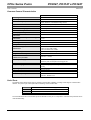
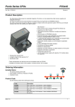
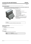
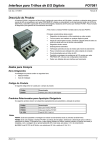
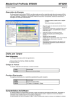
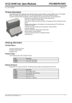
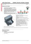
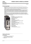
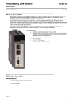
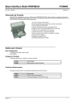
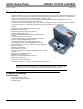
CPUs Series Ponto
PO3047, PO3147 e PO3247
Code: CT109108
Revision: B
Product Description
PO3x47 CLP CPU’s were designed for process control and supervision. Due to its hardware oriented architecture they can
deliver very low scan timing comparing to predecessors PO3x42 CPUs family. With these new CPU it can be obtained up
to 10 times more performance in CLP’s program Ladder instruction execution.
Additionally, these Ponto series CPU are characterized by a high integration of functions, programming on-line, high
capacity of memory and several integrated serial channels.
These CPU can be connected directly to the bus GBL, creating very compact systems of control and supervision. With the
use of field net interfaces, the CPUs become powerful controllers with capacity up to 4.096 I/O points.
•
•
•
•
•
•
•
•
•
•
•
•
•
•
•
•
•
•
•
Features:
Direct access to 30 modules through Series Point's bus.
Capacity up to 4.096 I/O points.
High-speed processing required by big systems.
Hardware arithmetic coprocessor
Connectivity to PROFIBUS bus through PROFIBUS-DP Master
interface
1 USB serial channel for programming
1 RS-232 serial channel, with configurable and programmable
protocols, including MODBUS master or slave.
1 RS-485 serial isolated channel, with configurable and
programmable protocols, including MODBUS master or slave.
Large Flash memory capacity up to 1 Mbyte for program application.
Ethernet connectivity.
WebServer characteristics.
CPU redundancy on local bus.
Diagnosis and status of local operation through alphanumeric display
in the panel.
Momentary key for diagnostic selection.
Diagnostics through operands.
Supporting to redundant PROFIBUS architecture.
Float point operands (% F).
Integer signed 32 bits operands (% I).
Internal power supply of + 24 Vdc with 700mA capacity of for I/O modules
Warning: The characteristics above refer to the PO3247 complete model. The other models
have subsets of these characteristics, as explained in the appropriate section of this CT.
Ordering Information
Included Items
The product packing contains:
• CPU PO3047 or PO3147 or PO3247.
• Installation Guide
Altus S. A.
1
CPUs Series Ponto
PO3047, PO3147 e PO3247
Code: CT109108
Revision: B
Product Code
The following codes are used when ordering the product:
Code
Description
PO3047
UCP 256K Flash, 16 Modules E/S, 1 USB, 1 RS-485, 1 RS-232,
MODBUS, Display, Ethernet
PO3147
UCP 512K Flash, 30 Modules E/S, 1 USB, 1 RS-485, 1 RS-232,
MODBUS, Display, PROFIBUS, Ethernet
PO3247
UCP 1M Flash, 30 Modules E/S, 1 USB, 1 RS-485, 1 RS-232, MODBUS,
Display, PROFIBUS, Ethernet, WebServer, Redundancy
Related Products
Depending on your system requirements, the following products may be ordered with the CPU:
Code
Description
PO6307
UCP PO3x47 Base
AL-1338
RS-485 Cable
AL-1715
RJ45-CFDB9 Cable
AL-1718
RJ45-CMDB9 RS232C Cable
AL-1719
RJ45-CMDB9 RS232 Cable
AL-1720
RJ45-CMDB9 RS232 / RS485 Cable
AL-1731
RJ45-CMDB9 RS485 Cable
AL-1746
USB CP/Microcomputer Cable
AL-2301
RS485 Network Cable (up to 1000 meters)
AL-2305
UCP/ Derivator Cable
AL-2306
RS485 Network Cable (up to 500 meters)
AL-2600
Derivator and Terminator
AL-2601
DB9 Connector to RS485 Network
AL-2700
Mathematical Functions
AL-2703
Communication Functions (F Module)
MT4100
MasterTool Programming MT4100
MT6000
MasterTool ProPonto w/ Manuals
MT8000
MasterTool Programming Extended Edition
PO4053
PROFIBUS DP Interface
PO7091
Industrial Ethernet Interface
PO8530
Battery ( spare part )
PO8524
Bus Terminator ( spare part )
PO8525
Derivator and Terminator to RS485 Network
PO6307: Base for PO3047, PO3147 and PO3247 CPUs.
AL-1715: Cable assembled with one RJ45 connector and one RS232 9-pin male sub-D connector IBM/PC standard. It is
used on COM1 and COM3 to connect the following equipment:
• HMI, which uses IBM/PC standard connector, for local supervision
• IBM/PC standard microcomputer with supervision software.
• IBM/PC standard microcomputer to UCP programming through MasterTool Software
AL-1718: Cable assembled with one RJ45 connector and one RS232 9-pin male sub-D connector Altus standard. It is used
on COM1 and COM3 to connect the following equipment:
• AL-1413 module, RS232 / RS485 Converter
Altus S. A.
2
CPUs Series Ponto
PO3047, PO3147 e PO3247
Code: CT109108
Revision: B
AL-1719: Cable assembled with one RJ45 connector and one RS232 9-pin male sub-D connector Altus standard. It is used
on COM1 and COM3 to connect the following equipment:
• Foton 5 or Foton 10 (MMI)
AL-1720: Cable assembled with one RJ45 connector and one RS232/RS485 9-pin male sub-D connector Altus standard. It
is used on COM1 and COM3 to connect the following equipment:
• Foton 1 or Foton 3 (MMI)
AL-1731: Cable assembled with one RJ45 connector and one RS485 9-pin male sub-D connector Altus standard. It is used
on COM2 to connect the PO8525 module.
AL-1746: standard USB cable for communication between microcomputer and serial channel COM1 of PO3x47 CPU.
AL-2301: Shielded cable with two pairs, no connectors. It is used on RS485 network:
• Connection between AL-2600 module or PO8525 module, maximum length of 1000 meters.
AL-2306: Shielded cable with two pairs, no connectors. It is used on RS485 network:
• Connection between AL-2600 module or PO8525 module, maximum length of 500 meters..
AL-2600: This module helps to connect a RS485 network (AL-2301 cable) to the AL-2305 cable.
PO8525: This module can be use to connect the CPU to a RS485 network. It has two terminals to network derivation,
termination resistors, and one RJ45 connector. The serial port COM2 is connected to this module through the AL-1731
cable.
Altus S. A.
3
CPUs Series Ponto
PO3047, PO3147 e PO3247
Code: CT109108
Revision: B
Characteristics
The 3 PONTO series CPUs are similar except for the following characteristics:
PO3047
Description
UCP 256K Flash, 16
Modules E/S, 1 USB, 1
RS-485, 1 RS-232,
MODBUS, Display,
Ethernet
PO3147
UCP 512K Flash, 30
Modules E/S, 1 USB, 1
RS-485, 1 RS-232,
MODBUS, Display,
PROFIBUS, Ethernet
PO3247
UCP 1M Flash, 30
Modules E/S, 1 USB, 1
RS-485, 1 RS-232,
MODBUS, Display,
PROFIBUS, Ethernet,
WebServer,
Redundancy
Application program memory –
Flash type
256K
512K
1M
Application program memory –
RAM type
256K
512K
1M
16
30
30
Maximum Modules
4
4
4
256 w/ 16 point modules
480 w/ 16 point modules
480 w/ 16 point modules
512 w/ 32 point modules
960 w/ 32 point modules
960 w/ 32 point modules
128 w/ 8 point modules
240 w/ 8 point modules
240 w/ 8 points modules
-
4096
4096
No
Yes
Yes
Ethernet TCP/IP interface support
(PO7091 or PO7092 module)
Yes
Yes
Yes
Ethernet TCP/IP interface with
WebServer support
(PO7091 or PO7092 module)
No
No
Yes
Maximum number of Segments
Maximum local I/O points
Maximum local analog I/O points
Maximum I/O points through
networks
Network interface support
(PO4053 module)
Serial interfaces
( see Serial Ports item )
1 x USB
1 x USB
1 x USB
1 x RS485
1 x RS485
1 x RS485
1 x RS232
1 x RS232
1 x RS232
COM 1 , COM2 e COM3
COM 1 , COM2 e COM3
COM 1 , COM2 e COM3
Yes
Yes
Yes
Serial port RS-485 (COM2)
Isolated
Isolated
Isolated
Serial port RS-232 (COM3)
Serial port USB (COM1)
RTS, CTS, DTR, DSR.
RTS, CTS, DTR, DSR.
RTS, CTS, DTR, DSR.
Floating point operand (%F)
Yes
Yes
Yes
Arithmetic coprocessor
Yes
Yes
Yes
MODBUS Protocol (master /
slave)
Yes
Yes
Yes
Embedded inside
module
Embedded inside
module
Embedded inside
module
(max. 700mA in first
bus)
(max. 700mA in first
bus)
(max. 700mA in first
bus)
No
No
Yes
Power supply
Redundancy
Serial Interfaces: The RS232 ports uses RJ45 connector with grounded shielding. The RS485 port uses DB 9 connector.
Base contains a bus terminator with switch.
Power supply: The CPUs PO3x47 include a internal power supply, which is feed with +24 Vdc. This power supply can
feed up to 700 mA to modules on first segment. If more I/O modules is necessary a PO8085 power supply must be
installed in the beginning of the next segment. MasterTool ProPonto – MT6000 helps for bus configuration, showing the
necessities of additional power supply (see specific manual). The power consumption of each module on bus can be seen
in its technical characteristics – CT.
Altus S. A.
4
CPUs Series Ponto
PO3047, PO3147 e PO3247
Code: CT109108
Revision: B
Common General Characteristics
PO3047, PO3147, PO3247
Module type
CPU
Hot Swap
Yes, for all I/O modules
Maximum analog I/O points
The limit is provide by the network bus. A system with 1000 analog
points, demands 11 PROFIBUS analog remotes
Typical bus scan time
0,5 ms with 480 digital I/O points
Local bus rate
12 Mbaud
Network connecting support
Yes, through network interfaces
Retentive memory
48 Kbytes
On-line programming
Yes
Middle time processing of 1025 boolean
instructions
0,6 ms
Middle time processing of 1025 floating point
instructions
4,1 ms
Real Time Clock
Yes
Watchdog
Yes
Battery for retentive operands
Inside the base, hot swap
Connector configuration
1 USB connector, COM 1
PO6302 Base
1 DB9 connector DB9, COM 2
Status and diagnostic indication
Alphanumeric display of 4 digits
Diagnostic selection key
Yes
1 RJ45 connector RJ45, COM 3
Isolation
RS485 Serial port RS485
1500 Vac / 1 minute
External power supply
19 a 30 Vdc including ripple;
Power dissipation
4,5 W
Bus power supply protection
The power supply is protected against over current or bus short
circuits.
Operating temperature
0 to 60 oC
Dimensions (W x H x D) mm
99 x 49 x 81 mm
Compatible bases
PO6307
Software Compatibility
MasterTool Extended Edition – MT8000 v5.10
maximum power consumption: 620 mA @ 24 Vdc
ProPonto - MT6000 v1.54
Serial Ports
The PO3x47 Ponto Series CPUs have an excellent communication capability, providing a wide range of communication
features. They have up to 3 serial ports with the following communication rates:
Communication Rate (bps)
COM1
115200
COM2
115200, 57600, 38400, 19200, 9600, 4800, 2400, 1200, 600, 300.
COM3
115200, 57600, 38400, 19200, 9600, 4800, 2400, 1200, 600, 300.
The next table shows the communication protocols allowed for each port. It is important to note that some protocols can be
used simultaneously.
Altus S. A.
5
CPUs Series Ponto
PO3047, PO3147 e PO3247
Code: CT109108
Revision: B
COM 1
COM 2
COM 3
RS232
RS485
RS232
Yes
Yes
Yes
MODBUS master
--
Yes
Yes
MODBUS slave
--
Yes
Yes
Alnet I slave
Included on all CPUs
complete
For further details see User’s Manual and Technical Characteristics (CTs) of the listed protocols.
The following table present some protocol combination examples:
COM1
Altus S. A.
COM 2
COM 3
MODBUS master
Example 01
Alnet I slave
MODBUS master
Example 02
Alnet I slave
MODBUS master
MODBUS slave
Example 03
Alnet I slave
MODBUS slave
MODBUS master
Example 04
Alnet I slave
MODBUS slave
Alnet I slave
Example 05
Alnet I slave
Alnet I slave
MODBUS slave
6
CPUs Series Ponto
PO3047, PO3147 e PO3247
Code: CT109108
Revision: B
Software Characteristics
PO3047 , PO3147, PO3247
Programming language
Relay diagram and logic blocks, structured in
modules with functions and sub-routines
On line programming
COM 1, COM 2, COM 3
Input (E) and output (S) operands
4096
Auxiliary operands (bits)
4096
Memory operands (M) (word 16bits)
Up to 9984
Decimal operands (D) (32 bits, BCD form + signal)
Up to 9984
Floating point operand (F) (32 bits, IEEE 754)
Up to 9984
Integer operands (I):
Up to 9984
32 bits value, 2 complement format 2
Memory table operand (TM) (word 16bits)
Up to 255 tables with 255 positions each
Floating point table operand (TF) (32 bits, IEEE
754)
Up to 255 tables with 255 positions each
Decimal table operand (TD) (32 bits, BCD format +
signal)
Up to 255 tables with 255 positions each
Integer table operands (TI):
Up to 255 tables with 255 positions each
Same as (I) operand
Memory constant (KM) (16 bits)
Stored in the application program
Decimal constant (KD) (32 bits, BCD form +
signal)
Stored in the application program
Floating point constant (32 bits, IEEE 754)
Stored in the application program
Integer constant (KI):
Stored in the application program
Same as (I) operand
Typical memory occupation by contact
instruction
7 bytes
Memory retention
Configurable for operands S, A, M, D, F
Always active for TM, TD e TF
File instruction
Permits the storage of great amounts of data
in blocks with up to 32 Kbytes
External interrupt for module E020
Permits related a input digital point to na
interrupt application module (E020)
Latency external interrupt E020
1,0 ms
Programmable time for module E018
2,5ms 3,125ms 5ms 10ms 25ms 50ms
• The total number of 4096 digital I/O points include inputs and outputs from local and remote buses. The sum of E with S
operands must be less or equal than the limit.
• All numeric operands (KM, KD, KF, , KI, M, D, F, I, TM, TD, TF and TI) allow arithmetic signal in the representation values.
The number of simple operands and tables (M, D, F, TM, TD, TF) is configured by each program, and is limited by the
available memory capacity of operands (48 Kbytes).
• The feature of memory retention can be attributed to the operands S, A, M, D, F e I through the programmer. The retentive
operands have their values preserved during power outage, whereas the non-retentive operands have their values zeroed.
The table operands are always retentive.
Altus S. A.
7
CPUs Series Ponto
PO3047, PO3147 e PO3247
Code: CT109108
Revision: B
Execution Times
The table below shows the execution time of main instructions in case of Ladder programming language, comparing to
PO3x42 series CPUs.
MOV M,M
PO3x47 (µ
µs) *
PO3x42 (µ
µs)
4,3
59,8
MOV I,I
5,8
83,6
MOV F,I
6,7
70,2
RNA
0,6
1,6
BOB
0,6
2,7
MOB 100 oper M
158,0
280,6
MOB 100 oper I
308,0
708,6
SOM M+M=M
6,5
35,4
SOM I+I=I
8,8
74,3
SUB F-F=F
9,1
114,4
MUL I=I*I
9,6
95,8
MUL F=F*F
9,8
135,9
DIV I=I*I
12,1
273,1
DIV F=F*F
10,6
285,4
WARNNIG:
* The times showed are concerned to PO3147 and PO3247. The PO3047 has different times.
For further details see User’s Manual.
Physical Dimensions
Dimensions in mm.
70702100
The Installation Manual should be consulted for general measurement of installation panel.
Altus S. A.
8
CPUs Series Ponto
PO3047, PO3147 e PO3247
Code: CT109108
Revision: B
Manuals
For correct application and utilization the User’s Manual – CPU Ponto Series must be consulted
For further technical details, configuration, installation and programming of Ponto series the table below should be
consulted.
Document Code
Description
CT109000
Technical Characteristics and configuration of Ponto series
MU209000
Utilization Manual of Ponto series IP20
MU209108
Utilization Manual PO3x47 – UCP of Ponto series
MU299604
Utilization Manual MasterTool XE
MU399003
Programming Manual ST
MU399102
Programming Manual Ladder
MU299040
Utilization Manual MT6000 - MasterTool ProPonto
CEs of Modules of Ponto series
Altus S. A.
9