1
EasyBuilder8000 User’s Manual Chapter 1 EasyBuilder Pro Installation and Startup Guide .............................................. 10
1.1 EasyBuilder Pro Installation.................................................................................... 10
1.2 Steps to Install EasyBuilder Pro ............................................................................. 11
Chapter 2 Project Manager Operations ........................................................................... 17
2.1 HMI IP, Password................................................................................................... 18
2.2 Utility....................................................................................................................... 20
2.2.1 Steps to Download Project via USB or CF Card .............................................. 21
2.3 Transfer .................................................................................................................. 22
2.3.1 Download......................................................................................................... 22
2.3.2 Upload ............................................................................................................. 23
2.4 Simulation............................................................................................................... 25
2.4.1 On-line Simulation/Off-line Simulation ............................................................. 25
2.5 Pass-Through......................................................................................................... 27
2.5.1 Ethernet ........................................................................................................... 27
2.5.2 COM port ......................................................................................................... 28
Chapter 3 Create an EasyBuilder8000 Project ................................................................ 30
3.1 Create a New Project ............................................................................................. 30
3.2 Save and Compile the Project ................................................................................ 34
3.3 Off-line and On-line Simulation............................................................................... 35
3.3.1 Off-line Simulation............................................................................................ 35
3.3.2 On-line Simulation............................................................................................ 36
3.4 Download the Project to HMI.................................................................................. 37
Chapter 4 Hardware Settings........................................................................................... 42
4.1 I/O Ports of HMI...................................................................................................... 42
4.1.1 USB Port.......................................................................................................... 42
4.1.2 Ethernet Port.................................................................................................... 42
4.1.3 CF Card or SD Card ........................................................................................ 42
4.1.4 Serial I/O Port .................................................................................................. 42
4.2 HMI System Settings .............................................................................................. 43
4.2.1 System Reset .................................................................................................. 43
4.2.2 System Toolbar................................................................................................ 45
4.2.2.1 Large Keyboard......................................................................................... 46
4.2.2.2 Small Keyboard ......................................................................................... 47
4.2.2.3 System Information ................................................................................... 47
4.2.2.4 System Setting .......................................................................................... 48
4.2.2.5 Touch Screen Calibration Mode ................................................................ 57
1 EasyBuilder8000 User’s Manual 4.3 HMI Download Settings .......................................................................................... 58
Chapter 5 System Parameter Settings............................................................................. 61
5.1 Device .................................................................................................................... 62
5.1.1 How to Control a Local PLC............................................................................. 63
5.1.2 How to Control a Remote PLC......................................................................... 68
11B5.1.3 How to Control a Remote HMI................................................................... 70
5.2 Model...................................................................................................................... 72
5.3 General................................................................................................................... 76
5.4 System Setting ....................................................................................................... 79
5.5 Security .................................................................................................................. 82
5.6 Font ........................................................................................................................ 85
5.7 Extended Memory .................................................................................................. 87
5.8 Printer/Backup Server ............................................................................................ 89
Chapter 6 Window Operations ......................................................................................... 91
6.1 Window Types........................................................................................................ 91
6.1.1 Base Window ................................................................................................... 91
6.1.2 Common Window............................................................................................. 92
6.1.3 Fast Selection Window .................................................................................... 93
6.1.4 System Message Window................................................................................ 94
6.2 Create, Set, and Delete a Window ......................................................................... 96
6.2.1 Create a Window ............................................................................................. 96
6.2.2 Window Settings ............................................................................................ 100
6.2.3 Open, Close and Delete a Window ................................................................ 101
Chapter 7 Event Log ...................................................................................................... 102
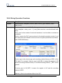
7.1 Event Log Management ....................................................................................... 104
7.1.1 Excel Editing .................................................................................................. 106
7.2 Create a New Event Log ...................................................................................... 110
Chapter 8 Data Sampling............................................................................................... 117
8.1 Data Sampling Management ................................................................................ 119
8.2 Create a New Data Sampling ............................................................................... 120
Chapter 9 Object General Properties............................................................................. 124
9.1 Selecting PLC....................................................................................................... 124
9.1.1 Setting the Reading and Writing Address ...................................................... 124
9.2 Using Shape Library and Picture Library .............................................................. 128
9.2.1 Settings of Shape Library............................................................................... 128
2 EasyBuilder8000 User’s Manual 9.2.2 Settings of Picture Library.............................................................................. 132
9.3 Setting Text Content............................................................................................. 135
9.4 Adjusting Profile Size............................................................................................ 140
9.5 Variables of Station Number................................................................................. 141
9.6 Broadcast Station Number ................................................................................... 143
Chapter 10 Security ....................................................................................................... 144
10.1 Settings of Password and Classes ..................................................................... 144
10.2 Security of Objects ............................................................................................. 146
10.3 Examples of Security.......................................................................................... 150
Chapter 11 Index Register ............................................................................................. 155
11.1 Introduction......................................................................................................... 155
11.2 Examples of Index Register................................................................................ 156
Chapter 12 Keyboard Design and Usage ...................................................................... 161
12.1 Steps to Design a Pop-up Keypad ..................................................................... 161
12.2 Steps to Design a Keyboard with Direct Window ............................................... 165
12.3 Steps to Design a Fixed Keyboard ..................................................................... 168
12.4 Creating UNICODE Keyboard ............................................................................ 169
Chapter 13 Objects ........................................................................................................ 171
13.1 Bit Lamp ............................................................................................................. 171
13.2 Word Lamp......................................................................................................... 174
13.3 Set Bit................................................................................................................. 179
13.4 Set Word ............................................................................................................ 183
13.5 Function Key ...................................................................................................... 191
13.6 Toggle Switch..................................................................................................... 198
13.7 Multi-State Switch............................................................................................... 201
13.8 Slider .................................................................................................................. 205
13.9 Numeric Input and Numeric Display ................................................................... 209
13.10 ASCII Input and ASCII Display ......................................................................... 221
13.11 Indirect Window ................................................................................................ 226
13.12 Direct Window .................................................................................................. 231
13.13 Moving Shape .................................................................................................. 235
13.14 Animation ......................................................................................................... 241
13.15 Bar Graph......................................................................................................... 246
13.16 Meter Display ................................................................................................... 254
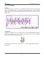
13.17 Trend Display ................................................................................................... 262
13.18 History Data Display ......................................................................................... 273
3 EasyBuilder8000 User’s Manual 13.19 Data Block Display ........................................................................................... 281
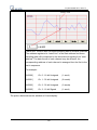
13.20 XY Plot ............................................................................................................. 294
13.21 Alarm Bar and Alarm Display ........................................................................... 308
13.22 Event Display ................................................................................................... 312
13.23 Data Transfer (Trigger-based).......................................................................... 321
13.24 Backup ............................................................................................................. 324
13.25 Media Player .................................................................................................... 331
13.26 Data Transfer (Time-based) ............................................................................. 343
13.27 PLC Control...................................................................................................... 346
13.28 Schedule .......................................................................................................... 353
13.29 Option List ........................................................................................................ 374
13.30 Timer ................................................................................................................ 381
13.31 Video In ............................................................................................................ 385
13.32 System Message .............................................................................................. 389
Chapter 14 Shape Library and Picture Library ............................................................... 391
14.1 Creating Shape Library....................................................................................... 391
14.2 Creating Picture Library...................................................................................... 398
Chapter 15 Label Library and Multi-Language Usage.................................................... 405
15.1 Introduction......................................................................................................... 405
15.2 Settings of Font of Label Library......................................................................... 407
15.3 How to Create a Label Library............................................................................ 408
15.4 Using Label Library ............................................................................................ 410
15.5 Settings of Multi-Language................................................................................. 411
Chapter 16 Address Tag Library .................................................................................... 414
16.1 Creating Address Tag Library............................................................................. 414
16.2 Using Address Tag Library ................................................................................. 417
Chapter 17 Transferring Recipe Data ............................................................................ 418
17.1 Updating Recipe Data with Ethernet or USB cable ............................................ 418
17.2 Updating Recipe Data with SD Card or USB Flash Drive................................... 420
17.3 Transferring Recipe Data ................................................................................... 421
17.4 Saving Recipe Data Automatically ..................................................................... 421
Chapter 18 Macro Reference......................................................................................... 422
18.1 Instructions to the Macro Editor.......................................................................... 422
18.2 Macro Construction ............................................................................................ 431
18.3 Syntax ................................................................................................................ 432
4 EasyBuilder8000 User’s Manual 18.3.1 Constants and Variables.............................................................................. 432
18.3.1.1Constants ............................................................................................... 432
18.3.1.2 Variables ............................................................................................... 432
18.3.2 Operators..................................................................................................... 435
18.4 Statement ........................................................................................................... 438
18.4.1 Definition Statement..................................................................................... 438
18.4.2 Assignment Statement................................................................................. 438
18.4.3 Logical Statements ...................................................................................... 439
18.4.4 Selective Statements ................................................................................... 440
18.4.5 Reiterative Statements................................................................................. 442
18.4.5.1 for-next Statements ............................................................................... 442
18.4.5.2 while-wend Statements ......................................................................... 444
18.4.5.3 Other Control Commands ..................................................................... 444
18.5 Function Blocks .................................................................................................. 446
18.6 Build-In Function Block....................................................................................... 449
18.6.1 Mathematical Functions ............................................................................... 449
18.6.2 Data Transformation .................................................................................... 455
18.6.3 Data Manipulation ........................................................................................ 460
18.6.4 Bit Transformation........................................................................................ 463
18.6.5 Communication ............................................................................................ 465
18.6.6 String Operation Functions .......................................................................... 481
18.6.7 Miscellaneous .............................................................................................. 508
18.7 How to Create and Execute a Macro.................................................................. 516
18.7.1 How to Create a Macro ................................................................................ 516
18.7.2 Execute a Macro .......................................................................................... 521
18.8 Some Notes about Using the Macro................................................................... 522
18.9 Use the Free Protocol to Control a Device ......................................................... 523
18.10 Compiler Error Message................................................................................... 529
18.11 Sample Macro Code......................................................................................... 535
18.12 Macro TRACE Function.................................................................................... 540
18.13 The Usage of String Operation Functions ........................................................ 549
18.14 Macro Password Protection.............................................................................. 560
Chapter 19 Set HMI as a MODBUS Server ................................................................... 562
19.1 Setting HMI as MODBUS Device ....................................................................... 562
19.1.1 Creating a MODBUS Server ........................................................................ 562
19.1.2 Read from / Write to MODBUS Server......................................................... 565
19.2 Changing the Station Number of a MODBUS Server in Runtime ....................... 568
19.3 About MODBUS Address Type .......................................................................... 569
5 EasyBuilder8000 User’s Manual Chapter 20 How to Connect a Barcode Device.............................................................. 570
20.1 How to Connect a Barcode Device..................................................................... 570
Chapter 21 Ethernet Communication and Multi-HMI Connection .................................. 574
21.1 HMI to HMI Communication ............................................................................... 575
21.2 PC to HMI Communication ................................................................................. 577
21.3 Operate the PLC Connected with other HMI. ..................................................... 579
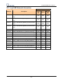
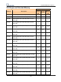
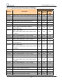
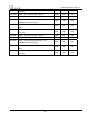
Chapter 22 System Reserved Words / Bits.................................................................... 581
22.1 The Address Ranges of Local HMI Memory....................................................... 582
22.1.1 Bits............................................................................................................... 582
22.1.2 Words .......................................................................................................... 583
22.2 HMI Time............................................................................................................ 584
22.3 User Name and Password.................................................................................. 585
22.4 Data Sampling.................................................................................................... 586
22.5 Event Log ........................................................................................................... 587
22.6 HMI Hardware Operation.................................................................................... 589
22.7 Local HMI Network Information .......................................................................... 590
22.8 Recipe and Extended Memory ........................................................................... 591
22.9 Storage Space Management.............................................................................. 593
22.10 Touch Position.................................................................................................. 594
22.11 Station Number Variables................................................................................. 595
22.12 Index Register .................................................................................................. 597
22.13 MTP File Information ........................................................................................ 598
22.14 MODBUS Server Communication .................................................................... 599
22.15 Communication Parameters Settings ............................................................... 601
22.16 Communication Status with PLC (COM) .......................................................... 604
22.17 Communication Status with PLC (Ethernet) ..................................................... 606
22.18 Communication Status with PLC (USB) ........................................................... 609
22.19 Communication Status with Remote HMI ......................................................... 610
22.20 Communication Status with Remote PLC......................................................... 613
22.21 Communication Error Messages & No. of Pending Cmd.................................. 616
22.22 Miscellaneous Functions .................................................................................. 617
22.23 Remote Print/Backup Server ............................................................................ 619
22.24 EasyAccess...................................................................................................... 620
22.25 Pass-Through Settings ..................................................................................... 621
22.26 Disable PLC No Response Dialog Box............................................................. 622
22.27 HMI and Project Key......................................................................................... 623
22.28 Fast Selection Window Control ........................................................................ 624
6 EasyBuilder8000 User’s Manual 22.29 Input Object Function ....................................................................................... 625
22.30 Local/Remote Operation Restrictions ............................................................... 626
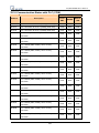
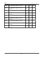
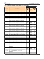
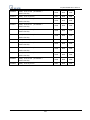
Chapter 23 HMI Supported Printers............................................................................... 627
Chapter 24 Recipe Editor............................................................................................... 630
24.1 Introduction......................................................................................................... 630
24.2 Settings of Recipe Editor .................................................................................... 632
Chapter 25 EasyConverter ............................................................................................ 634
25.1 Introduction......................................................................................................... 634
25.2 Settings of EasyConverter.................................................................................. 635
25.2.1 How to Export to Excel................................................................................. 635
25.2.2 How to Use Scaling Function....................................................................... 638
25.2.3 How to Use Multi-File Conversion................................................................ 641
25.3 Enable Setting File ............................................................................................. 643
25.3.1 For “Combination” and “Enable Setting File”................................................ 645
25.4 Command Line ................................................................................................... 647
Chapter 26 EasyPrinter.................................................................................................. 648
26.1 Using EasyPrinter as a Printer Server ................................................................ 649
26.1.1 Setup Procedure in EasyPrinter................................................................... 649
26.1.2 Setup Procedure in EasyBuilder8000 .......................................................... 651
26.2 Using EasyPrinter as a Backup Server............................................................... 653
26.2.1 Setup Procedure in EasyPrinter................................................................... 653
26.2.2 Setup Procedure in EasyBuilder8000 .......................................................... 654
26.3 EasyPrinter Operation Guide.............................................................................. 657
26.3.1 Appearance ................................................................................................. 657
26.3.2 Operation Guide........................................................................................... 658
26.4 Convert Batch File .............................................................................................. 664
26.4.1 The Default Convert Batch File .................................................................... 664
26.4.2 Specialized Criteria ...................................................................................... 665
26.4.3 The Format of a Convert Batch File ............................................................. 666
26.4.4 The Order of Examining Criteria .................................................................. 667
Chapter 27 EasySimulator ............................................................................................. 668
27.1 Prepare Files ...................................................................................................... 668
27.2 Modify the Content of xob_pos.def..................................................................... 669
Chapter 28 Multi-HMI Intercommunication (Master-Slave Mode) .................................. 671
28.1 How to Create a Project of Master HMI .............................................................. 672
7 EasyBuilder8000 User’s Manual 28.2 How to Create a Project of Slave HMI ................................................................ 673
28.3 How to Connect MT500 Project of Slave HMI .................................................... 676
Chapter 29 Pass-Through Function ............................................................................... 680
29.1 Ethernet Mode.................................................................................................... 681
29.1.1 How to Change the Virtual Serial Port ......................................................... 682
29.1.2 How to Use Ethernet Mode.......................................................................... 685
29.2 COM Port Mode ................................................................................................. 687
29.2.1 Settings of COM Port Mode ......................................................................... 687
29.2.2 HMI Work Mode ........................................................................................... 689
29.3 Using System Reserved Addresses to Enable Pass-Through Function ............. 693
Chapter 30 Project Protection ........................................................................................ 694
30.1 XOB password ................................................................................................... 694
30.2 Decompilation is prohibited ................................................................................ 695
30.3 Disable HMI upload function [LB9033] ............................................................... 696
30.4 Project protection [Project Key] .......................................................................... 697
30.5 Project password [MTP file]................................................................................ 698
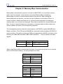
Chapter 31 Memory Map Communication ..................................................................... 700
Chapter 32 ASCII Protocol............................................................................................. 710
32.1 Command List .................................................................................................... 710
32.2 Optional Parameters........................................................................................... 711
32.3 Network Support................................................................................................. 712
32.3.1 Wiring........................................................................................................... 712
32.3.2 Addressing ................................................................................................... 712
32.3.3 Broadcast Messages ................................................................................... 712
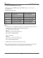
32.4 Command Usage ............................................................................................... 713
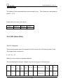
32.4.1 RD (Batch Read).......................................................................................... 713
32.4.1.1 Request ................................................................................................. 713
32.4.1.2 Reply ..................................................................................................... 714
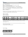
32.4.2 WD (Batch Write) ......................................................................................... 715
32.4.2.1 Request ................................................................................................. 715
32.4.2.2 Reply ..................................................................................................... 716
32.4.3 RR (Random Read) ..................................................................................... 717
32.4.3.1 Request ................................................................................................. 717
32.4.3.2 Reply ..................................................................................................... 718
32.4.4 RW (Random Write)..................................................................................... 719
32.4.4.1 Request ................................................................................................. 719
8 EasyBuilder8000 User’s Manual 32.4.4.2 Reply ..................................................................................................... 720
32.4.5 RC (Read Coils)........................................................................................... 720
32.4.5.1 Request ................................................................................................. 720
32.4.5.2 Reply ..................................................................................................... 721
32.4.6 WC (Write Coils) .......................................................................................... 722
32.4.6.1 Request ................................................................................................. 722
32.4.6.2 Reply ..................................................................................................... 724
32.4.7 Error Codes ................................................................................................. 725
Chapter 33 EasyDiagnoser ............................................................................................ 726
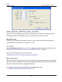
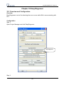
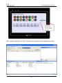
33.1 Overview and Configuration ............................................................................... 726
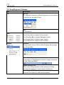
33.2 EasyDiagnoser Settings ..................................................................................... 729
33.3 Error Code.......................................................................................................... 736
33.4 Save As .............................................................................................................. 737
33.5 Window Adjustment............................................................................................ 738
Chapter 34 AB EtherNet/IP Free Tag Names ................................................................ 739
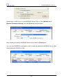
34.1 Import User-Defined AB Tag to EB8000............................................................. 740
34.2 Adding New Data Type....................................................................................... 742
34.3 Paste .................................................................................................................. 745
34.4 Miscellaneous..................................................................................................... 748
34.5 Module-Defined .................................................................................................. 749
Chapter 35 FTP Server Application ............................................................................... 753
35.1 Login FTP Server ............................................................................................... 753
35.2 Backup History Data and Update Recipe Data................................................... 753
9 EasyBuilder8000 User’s Manual Chapter 1 EasyBuilder Pro Installation and Startup Guide
1.1 EasyBuilder Pro Installation
Software:
Download EasyBuilder Pro configuration software from EasyBuilder Pro CD or visiting
Weintek Labs, Inc.’s website at http://www.weintek.com to obtain all software versions
available (including Simplified Chinese, Traditional Chinese, English, Italian, Korean,
Spanish, and French version) and latest upgraded files.
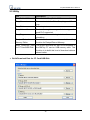
Hardware Requirements (Recommended):
CPU: INTEL Pentium II or higher
Memory: 64MB or higher
Hard Disk: 2.5GB or higher (Disc space available at least 10MB)
CD-ROM: 4X or higher
Display: 256 color SVGA with 800 x 600 resolution or greater
Keyboard and Mouse
Ethernet: for project downloading/uploading
RS-232 COM: At least one available RS-232 serial port required for on-line simulation
Printer
Operating System:
Windows 2000 / Windows NT / Windows XP / Windows Vista / Windows 7.
10
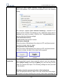
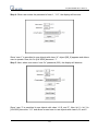
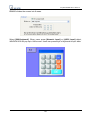
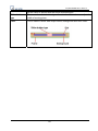
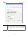
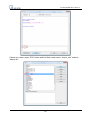
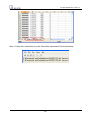
EasyBuilder8000 User’s Manual 1.2 Steps to Install EasyBuilder Pro
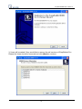
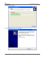
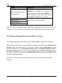
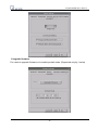
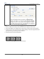
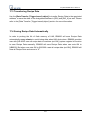
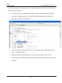
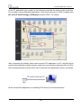
1. Installing EasyBuilder Pro:
Put the EasyBuilder Pro Installation CD into the CD drive. The computer will run the
program automatically and bring up a screen showing an area to click to begin the
EasyBuilder Pro installation. If the auto-run sequence does not start, browse the CD, and
find the root directory of [Autorun.exe] manually. The installation screen is shown
below.
`
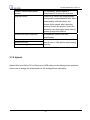
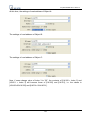
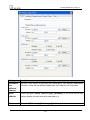
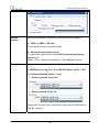
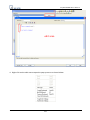
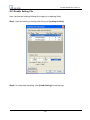
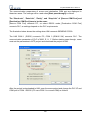
2. Click [Install], users will see the window below, select the language and click [Next]
following the installation instructions.
11
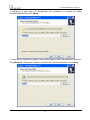
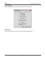
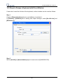
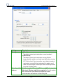
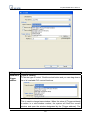
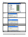
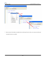
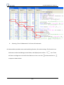
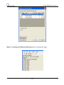
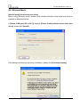
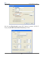
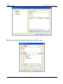
EasyBuilder8000 User’s Manual 3. Users will be asked if they would like to remove the old versions of EasyBuilder Pro.
Please tick those should be removed and click [Next] to continue.
12
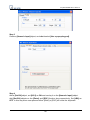
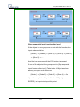
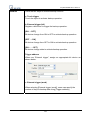
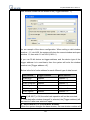
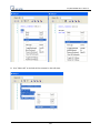
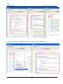
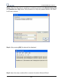
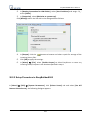
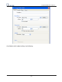
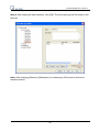
EasyBuilder8000 User’s Manual 4. Designate a new folder for EasyBuilder Pro installation or choose the folder
recommended and then click [Next].
5. Users will be enquired to select a start menu folder to save the program’s shortcuts.
Click [Browse] to designate a folder or use the folder recommended then click [Next].
13
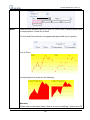
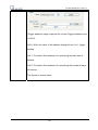
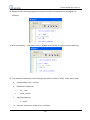
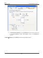
EasyBuilder8000 User’s Manual 6. Users will be enquired if there are any additional tasks to be done. For example: [Create
a desktop icon]. Tick it if needed then click [Next] to continue.
7. At this moment all the settings are done. Please check if they are all correct. If any
changes need to be made, click [Back] or click [Install] to start installing.
14
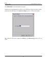
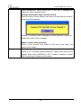
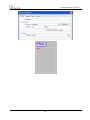
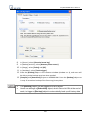
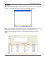
EasyBuilder8000 User’s Manual 8. Installation processing.
9. Click [Finish] to complete the installation.
15
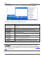
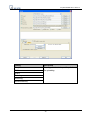
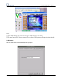
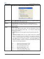
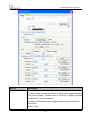
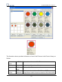
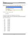
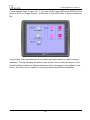
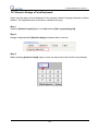
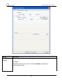
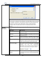
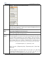
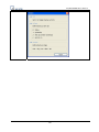
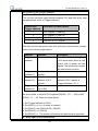
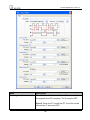
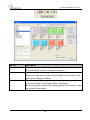
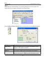
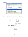
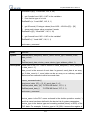
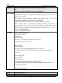
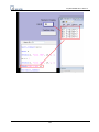
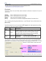
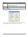
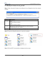
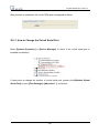
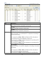
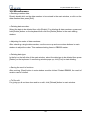
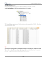
EasyBuilder8000 User’s Manual 10. Start EasyBuilder Pro project from menu [Start] / [All Programs] / [EB8000].
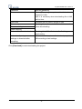
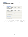
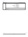
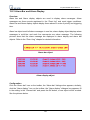
The description of each item in EasyBuilder Pro menu:
Item
Description
When using AB Tags, this tool can be applied to edit Tags
structure
EasyBuilder Pro editing software
Conversion tool for Data Sampling and Event Log
Communication monitoring tool via online simulation
Remote printer server
Tool for executing simulation without installing EasyBuilder
Pro
EasyBuilder Pro project management
Tool for setting format of Recipe data. Users can open Recipe
data or data in External Memory here.
Notes for EasyBuilder Pro version and latest information
To uninstall EasyBuilder Pro
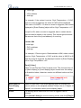
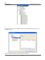
HMI i Series support downloading/uploading project via USB cable.
After installing EasyBuilder Pro, Please go to [Computer Management] /
[Device Manager] to check if USB driver is also installed, if not, please refer to installation
steps to manually install.
16
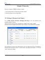
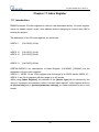
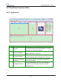
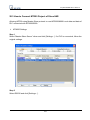
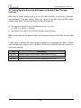
EasyBuilder8000 User’s Manual Chapter 2 Project Manager Operations
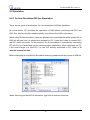
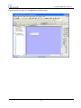
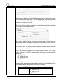
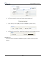
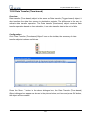
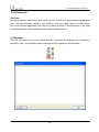
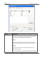
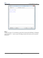
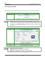
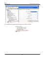
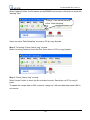
After installing EB8000 software, users will see a [Project Manager] shortcut, double click
it, users will see a window as shown below.
The Project Manager is a software shell for launching several utilities. Some functions are
duplicated in the EasyBuilder8000 screen-editing program. Project Manager can operate
as a stand-alone program.
In this chapter, each function will be introduced respectively.
17
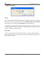
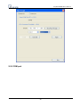
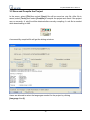
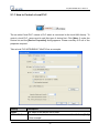
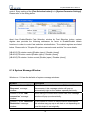
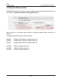
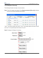
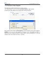
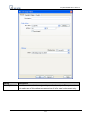
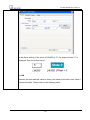
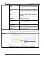
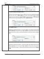
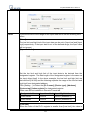
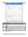
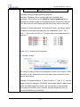
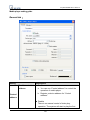
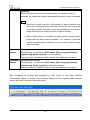
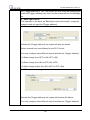
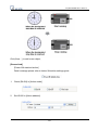
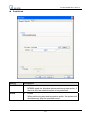
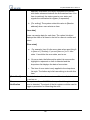
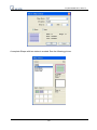
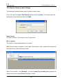
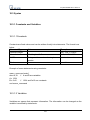
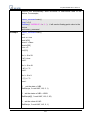
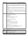
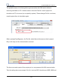
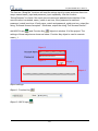
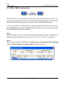
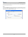
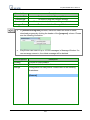
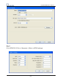
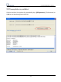
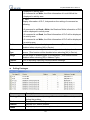
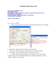
EasyBuilder8000 User’s Manual 2.1 HMI IP, Password
Settings
When operating MT8000/MT6000 HMI by Ethernet or USB cable, users need to designate
the correct IP address and password in HMI. Press [Settings], [Reset and Download]
functions share a set of password while [Upload] function uses another set.
The password provides protection against unauthorized access to the HMI. Be sure to
record any password change, otherwise, while resetting password to default, the project
and data in HMI will be completely erased.
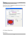
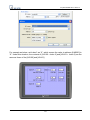
Reboot HMI
There are certain situations that the HMI should reboot, for example, when updating the
files in it. Users don’t need to cut power while rebooting. After rebooting, everything returns
to the conditions of startup.
18
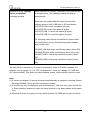
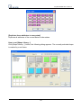
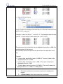
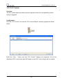
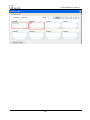
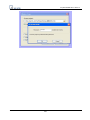
EasyBuilder8000 User’s Manual Set the correct IP address when operating HMI via Ethernet.
19
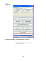
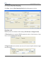
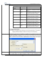
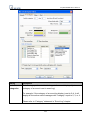
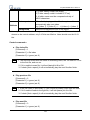
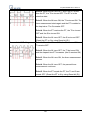
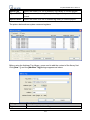
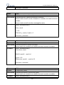
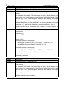
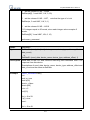
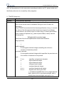
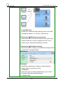
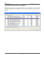
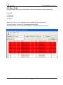
EasyBuilder8000 User’s Manual 2.2 Utility
Item
Description
EasyBuilder8000
To launch the EasyBuilder8000 screen editor.
Easy Converter
Conversion tool for Data Sampling and Event
Log.
Easy Printer
Remote printer server.
EasyAddressViewer
Review the register range of device types for
each PLC supported.
EasyDiagnoser
Communication monitoring tool via online
simulation.
Recipe / Extend
Memory Editor
Provide file format conversion and data editing
function for Recipe/Extend Memory.
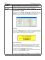
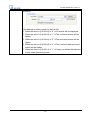
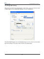
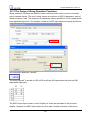
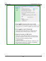
Build Download Data The project and data can also be downloaded to
for CF Card/USB Disk the HMI by CF card or USB memory stick. This
function is to build this kind of download data as
shown below.
* Build Download Data for CF Card/USB Disk
20
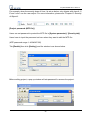
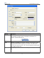
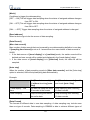
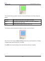
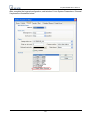
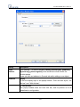
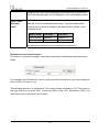
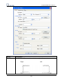
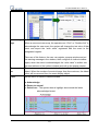
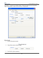
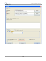
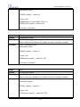
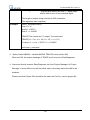
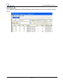
EasyBuilder8000 User’s Manual Setting
Description
Insert CF card or USB stick to PC and press
Select the folder to save
download data
Project
Recipe (RW)
[Browse…] to assign the file path (or
directory name) and then press [Build]. The
whole contents of the source files will be
downloaded to USB stick or CF card
Press [Browse…] to assign the desired
specific files for download data.
Recipe A (RW_A)
Data log
Note: The path of download data should avoid designating root directory of PC. For
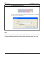
example, “c:\”, also, directory name such as “f:\\” is illegal and should be written as “f:\”.
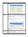
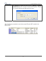
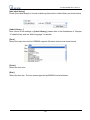
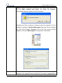
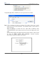
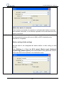
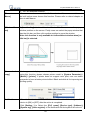
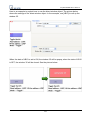
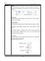
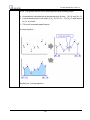
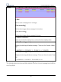
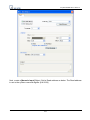
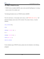
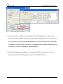
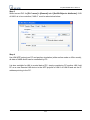
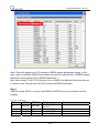
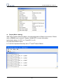
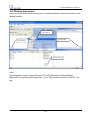
2.2.1 Steps to Download Project via USB or CF Card
Take downloading data to the folder named “123” (K:\123) in USB stick for example.
When USB stick (project or recipe included) is inserted to the HMI, a pop-up [Download /
Upload] dialog will appear after few seconds. Please select [Download] and input
Download Password. Check [Download project files] and [Download history files] in
[Download Settings] dialog, and then press [OK]. After that, [Pick a Directory] dialog
will appear. Please select directory: usbdisk/device-0/123 and then press [OK]. Project
will be automatically updated.
Note: Even if users only download historical files, it is still necessary to reboot HMI
manually.
21
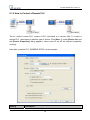
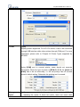
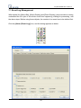
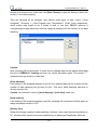
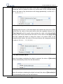
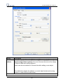
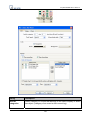
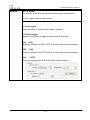
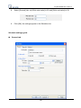
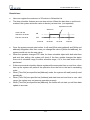
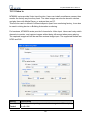
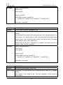
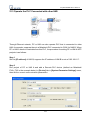
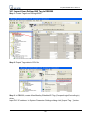
EasyBuilder8000 User’s Manual 2.3 Transfer
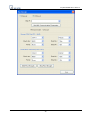
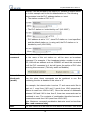
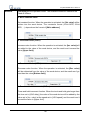
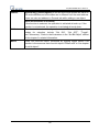
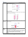
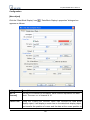
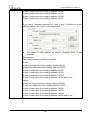
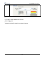
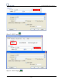
2.3.1 Download
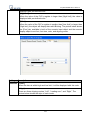
Download source files to HMI through Ethernet or USB cable. Press [Download] and the
dialog displays as below:
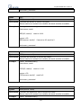
Setting
Firmware
Project
RW
Description
Check this to update all of the kernel
programs of HMI. It is necessary when
the latest EB8000 version is
downloaded the first time.
To assign the desired specific path for
file downloading.
RW_A
Data log
22
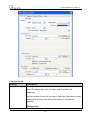
EasyBuilder8000 User’s Manual Install X-series media-player
drivers
It is necessary when EB8000 is
downloaded to X series the first time.
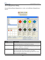
Startup Screen
If this box is ticked, the assigned BMP
picture will be downloaded to HMI. After
downloading, HMI will reboot, this
picture will be shown after rebooting,
and then load in the project. Users are
allowed to use their logos as the start up
screen through this method.
Reboot HMI after download
Automatically reboot HMI after
downloading.
Reset recipe
Check the box to erase the selected
specific files in HMI before downloading
process.
Reset event log
Reset data log
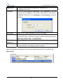
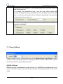
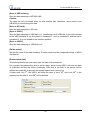
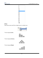
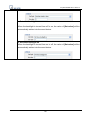
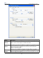
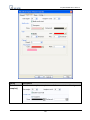
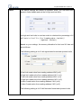
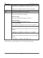
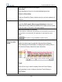
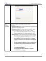
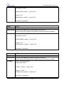
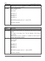
2.3.2 Upload
Upload files from HMI to PC by Ethernet or USB cable and the dialog shows as below:
Users have to assign the desired path for file storage before uploading.
23
EasyBuilder8000 User’s Manual Setting
Project
RW
Description
To assign the desired specific path for
file uploading.
RW A
Data log
Event log
Extend Memory
24
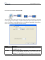
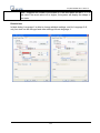
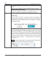
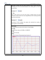
EasyBuilder8000 User’s Manual 2.4 Simulation
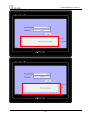
2.4.1 On-line Simulation/Off-line Simulation
There are two types of simulations: On -line simulation & Off-line simulation.
By virtual device, PC simulates the operations of HMI without connecting with PLC and
HMI. This shortens the time needed greatly even without the HMI in your hand.
While using Off-line simulation, users are allowed not to download the written project file to
HMI, but still see how it is shown and operated on PC. Users don’t need to connect PLC
with PC under this mode. On the contrary, On-line simulation is executed by connecting
PC with PLC and accurately set the communication parameters. When simulating on PC,
if the control target is a local PLC (i.e. the PLC directly connected to PC), there is 10
minutes simulation limit.
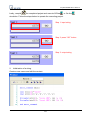
Before executing On-line/Off-line Simulation features, please select the source of XOB file.
When executing on-line/off-line simulation, right click to use two functions:
25
EasyBuilder8000 User’s Manual a. “Run EasyDiagnoser”
Execute EasyDiagnoser to monitor current communication status.
b. “Screenshot”
Capture and save current screen image as picture file in the screenshot folder
under installation directory.
26
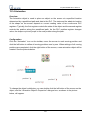
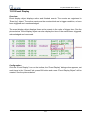
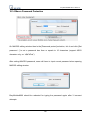
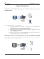
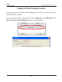
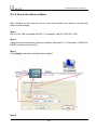
EasyBuilder8000 User’s Manual 2.5 Pass-Through
The pass-through function allows the PC application to connect PLC via HMI. In this
function, the HMI acts as a converter.
Pass-through provides two types of modes: Ethernet and COM port. Click [Pass-through]
button on Project Manager to start the settings.
For more information, please refer to related chapter.
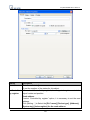
2.5.1 Ethernet
27
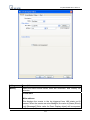
EasyBuilder8000 User’s Manual 2.5.2 COM port
28
EasyBuilder8000 User’s Manual 29
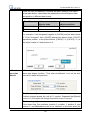
EasyBuilder8000 User’s Manual Chapter 3 Create an EasyBuilder8000 Project
In this Chapter, we will take Mitsubishi PLC as an example to illustrate how to create and
compile a new EB8000 project, to simulate it on PC and to download the project to HMI.
3.1 Create a New Project
First of all, click [New] icon on the toolbar to create a new project.
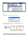
Select HMI Model, check [Use template] and click [OK].
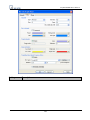
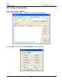
Under [Device] Tab, click [New…] button to correctly set up the [Device Properties] for
communicating with the PLC.
30
EasyBuilder8000 User’s Manual Click [OK], device “MISUBISHI FX0n/FX2” is added to the [Device List].
31
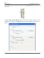
EasyBuilder8000 User’s Manual Now, if users would like to add a new object, such as [Toggle Switch], click the icon on
the tool bar.
A [New Toggle Switch Object] dialog will be shown as below. Correctly set the
parameters of the object, click [OK] and place the object wherever users like in the
window.
32
EasyBuilder8000 User’s Manual A project with an object is completed as shown below.
33
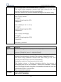
EasyBuilder8000 User’s Manual 3.2 Save and Compile the Project
In the menu, select [File] then select [Save], file will be saved as .mtp file. After file is
saved, select [Tools] then select [Compile] to compile the project and check if the project
can run correctly. A .xob file will be obtained after correctly compiling. A .xob file is needed
while downloading to HMI.
A successfully compiled file will get the dialog as below:
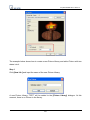
Users are allowed to select the languages needed for the project by clicking
[Language 1 to 8].
34
EasyBuilder8000 User’s Manual 3.3 Off-line and On-line Simulation
There are two types of simulations: On -line simulation & Off-line simulation.
While using Off-line simulation, users don’t need to connect PLC with PC but still see how
PLC is operated via a virtual device. On the contrary, On-line simulation is executed by
connecting PC with PLC and accurately set the communication parameters.
Note: When doing On-line simulation on PC, if the target is a local PLC (i.e. the PLC
directly connected to PC), there is a 10-minutes simulation limit.
3.3.1 Off-line Simulation
To execute, click [Off-line Simulation].
After clicking, users will see their project shown as below.
35
EasyBuilder8000 User’s Manual 3.3.2 On-line Simulation
To execute, click [On-line Simulation] after correctly connecting the device.
36
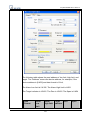
EasyBuilder8000 User’s Manual 3.4 Download the Project to HMI
In the menu, select [Tool] then select [download] to download the project file to HMI.
Before downloading, be sure to check if all the settings are correct.
Setting
Description
HMI IP
Assign the IP address of HMI
Password
Input the password
Firmware
Check [Firmware] to update all of the kernel
programs of HMI.
37
EasyBuilder8000 User’s Manual Note: It is necessary when downloading file to
HMI the first time.
Font Files
Download the font used in project to HMI.
Reset recipe
Checking these, the selected files will be
erased before downloading.
Reset event log
Reset data log
Reboot HMI after download
Checking this, HMI will reboot after finishing
downloading.
Automatically using current If this is checked, system will download project
settings to download after to HMI according to last settings.
compiling
* Automatically Using Current Settings to Download after Compiling
1. Firstly, please go to [Option] / [Function Properties] then tick [Automatic save and
compile when download and simulate].
2. Secondly, in [Download] dialogue box, tick [Automatically using current settings to
download after compiling] to enable this function.
38
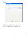
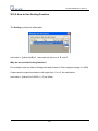
EasyBuilder8000 User’s Manual Click [Download] to start downloading the project.
Another way to download project to HMI is to set a HMI name. Before using this function,
please input the HMI Name in the [System settings] window in HMI as shown below.
After setting the HMI Name, please click [Name] in the [Download] window on PC as
below,
39
EasyBuilder8000 User’s Manual Setting
Description
HMI Name
Input the HMI name for downloading project
Search
Input the HMI name to search the designated HMI
Search all
Click to search the HMI shares the same network
40
EasyBuilder8000 User’s Manual Password
Input the password
Firmware
Check [Firmware] to update all of the kernel
programs of HMI.
Note: It is necessary when downloading file to HMI
the first time.
Font Files
Download the font used in project to HMI.
Reset recipe
Checking these, the selected files will be erased
before downloading.
Reset event log
Reset data log
Reboot HMI after download
Checking this, HMI will reboot after finishing
downloading.
Automatically using current
settings to download after
compiling
If this is checked, system will download project to
HMI according to last settings.
Click [Download] to start downloading the project.
41
EasyBuilder8000 User’s Manual Chapter 4 Hardware Settings
4.1 I/O Ports of HMI
4.1.1 USB Port
Support devices with USB interface, such as mouse, keyboard, USB stick, printer…etc.
4.1.2 Ethernet Port
Connect devices with Ethernet communication interface, such as PLC, laptop…etc;
support exchanging data via Network.
4.1.3 CF Card or SD Card
Download/ Upload project via CF Card or SD Card, including Recipe transfer, Event Log,
Data Log…etc.
4.1.4 Serial I/O Port
COM ports, RS-232, RS485-2W/4W, can be connected to PLC or other peripheral devices.
Here we view RS-422 the same as RS-485 (4 wire). Please refer to the “PLC connection
42
EasyBuilder8000 User’s Manual guide” to make sure that PLC and HMI are correctly connected. Meanwhile, please make
sure all DIP switches at the back of HMI are pulled down (means off, the default value).
In addition, Weintek provides [MT8-COM1 Multi-Connector cable] and [MT8-COM3
Multi-Connector cable] to expand one COM port to multiple independent COM ports so
that the convenience and efficiency of the operation can be improved.
4.2 HMI System Settings
Before operating HMI, users have to complete the HMI system settings. After this, users
can develop their own operation interface through EB8000 editing software.
The following illustrates each system setting respectively.
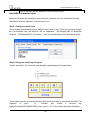
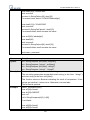
4.2.1 System Reset
Each HMI is equipped with a set of reset button and DIP switch. When users use DIP
switch to change modes, corresponding functions will be triggered.
If system password is lost or forgotten, users can set DIP Switch 1 to “ON” and the rest
remain “OFF”, then reboot HMI.
43
EasyBuilder8000 User’s Manual HMI will switch to touch screen calibration mode. After calibration, the pop-up window
appears as shown below. Users will be inquired if they would like to restore the system
password to the default.
When [YES] is chosen, another pop-up dialog appears as below. The system will ask
users to type [yes] to confirm to restore system password to default. Then click [OK].
(The default password is 111111. However, other passwords, including download and
upload password, have to be reset.)
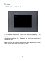
The illustration above shows the steps to restore factory settings of T and i Series HMI. For
X Series, users will need a connected USB keyboard, and press any key (or space key)
right when the first image displayed as HMI power ON to enter the menu. Select "Factory
Mode", the window mentioned will pop up when system displays project. In case users
may miss the very first image shown, to press space key continuously since HMI power
ON will ensure entering the system setting window.
Note: The project and data in the HMI will all be removed once it is reset.
44
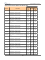
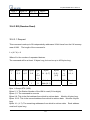
EasyBuilder8000 User’s Manual SW1 SW2 SW3SW4
Mode
ON OFF OFF OFF Touch screen calibration mode (T, i series)
OFF ON OFF OFF Hide System Toolbar (i , X V2 series)
OFF OFF ON OFF Boot loader mode
OFF OFF OFF ON Enable front panel power switch (X series)
OFF OFF OFF OFF Normal
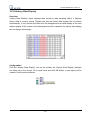
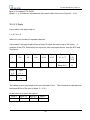
4.2.2 System Toolbar
After rebooting HMI, users can set the system with System Toolbar at the bottom of the
screen. Normally, this bar is hidden automatically. Only by touching the target at the
right-bottom corner of screen will the System Toolbar pops up.
45
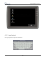
EasyBuilder8000 User’s Manual 4.2.2.1 Large Keyboard
Use large keyboard to input text information.
46
EasyBuilder8000 User’s Manual 4.2.2.2 Small Keyboard
Use small keyboard to input numerical information.
4.2.2.3 System Information
Network: Display Network information, including HMI IP address and related information.
Version: Display information of the HMI system version.
47
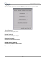
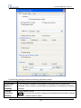
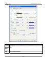
EasyBuilder8000 User’s Manual 4.2.2.4 System Setting
Set or modify system parameters. Password has to be confirmed for security.
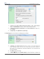
a. Network
A project can be downloaded to HMI via Ethernet. The IP address of target (HMI) must be
correctly set. If [Auto Get IP Address] is selected, IP address will be automatically
assigned from local DHCP network. If [IP address get from below] is selected, IP
address and other network information have to be inputted by the user.
48
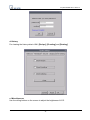
EasyBuilder8000 User’s Manual b. Time/Date
This page is for setting HMI local time and date.
49
EasyBuilder8000 User’s Manual c. Security
The default of the password is 111111. EB8000 provides strict security for the HMI.
[Local Password]
Password for entering the system
[Upload Password]
Password for uploading the project
[Download Password]
Password for downloading the project
[Upload (History) Password]
Password for uploading the historical data.
Password confirmation:
50
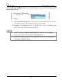
EasyBuilder8000 User’s Manual d. History
For clearing the history data in HMI: [Recipe], [Eventlog] and [Datalog].
e. Miscellaneous
Use the rolling bottom on the screen to adjust the brightness of LCD.
51
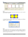
EasyBuilder8000 User’s Manual f. Upgrade firmware
For users to upgrade firmware or to enable portrait mode. (Supported only by I series)
52
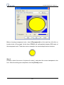
EasyBuilder8000 User’s Manual g. CF card Status
When new external device is detected, this function will be enabled.
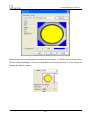
h. VNC server
Allows users to monitor and control the remote HMI through Ethernet.
53
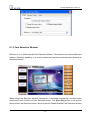
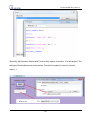
EasyBuilder8000 User’s Manual Step 1. Enable VNC server and set the password in HMI.
Step 2. Install Java IE or VNC viewer in PC.
After installing Java IE, enter HMI IP: (The following takes http://192.168.1.28 as an
example)
54
EasyBuilder8000 User’s Manual For VNC viewer, enter HMI IP address and password.
55
EasyBuilder8000 User’s Manual Note:
(1) One HMI allows only one user to log in VNC server at one time.
(2) If users leave VNC server unused for one hour, HMI system will log out automatically.
i. HMI name
Set the HMI name to download/upload a project.
56
EasyBuilder8000 User’s Manual 4.2.2.5 Touch Screen Calibration Mode
In this mode when users power on MT8000 series, the screen will display a “+” sign
upper-left of the screen. Use a stylus or finger to touch the center of the “+” until it moves.
The “+” moves to upper-left, upper-right, lower -left, lower-right and center of screen.
When all five “+” are touched, the “+” will disappear. The Touch Screen parameter will be
stored at Flash Rom.
Note: Only X series HMI are with this shortcut of touch screen calibration mode in system
toolbar. For other series, please use DIP switch 1 to adjust.
57
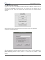
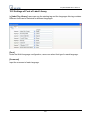
EasyBuilder8000 User’s Manual 4.3 HMI Download Settings
A project or data can be downloaded to HMI via SD card or USB disk. Insert SD card or
USB disk and designate the directory path. All contents under this directory will be
downloaded to HMI. When HMI detects new external devices, the following screen
appears:
Several functions can be selected at this time and some of them need password
confirmation as illustrated below:
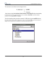
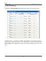
After the password is confirmed, directory names of the SD card…etc will be displayed in
[Pick a Directory] window as below (pccard -> CF card (SD card); usbdisk -> USB
device)
58
EasyBuilder8000 User’s Manual Select the download path for project and click [OK] for downloading.
Note: Users have to create download data from [Build Download Data for CF/USB Disk]
in Project Manager.
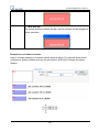
Generally, Project Manager divides downloaded files into two directories:
MT8000
Project storage
History
When users download the history data, this directory will be created.
An example which shows the directory of target file is shown below.
59
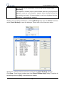
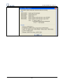
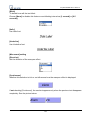
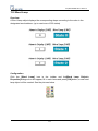
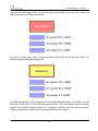
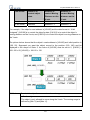
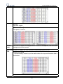
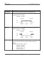
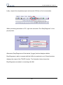
EasyBuilder8000 User’s Manual The structure of saved data is as the diagram below:
Users have to select the top layer of the directory of the target file when downloading.
In other words, take the structure above as an example; download must be selected
instead of choosing mt8000 or history.
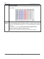
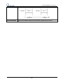
Take the illustration below as another example: If USB disk only stores mt8000 directory
but don’t include history data. In this case, users must choose disk_a_1 (the top layer of
target file that contains file of mt8000) to correctly download the file.
60
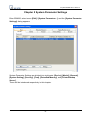
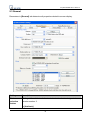
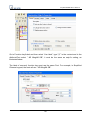
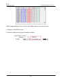
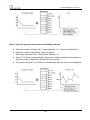
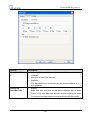
EasyBuilder8000 User’s Manual Chapter 5 System Parameter Settings
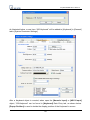
Enter EB8000, select menu [Edit] / [System Parameters…] and the [System Parameter
Settings] dialog appears:
System Parameter Settings are divided into eight parts: [Device], [Model], [General],
[System Setting], [Security], [Font], [Extended Memory], and [Printer/Backup
Server].
These will be introduced respectively in this chapter.
61
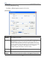
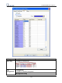
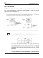
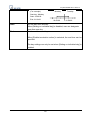
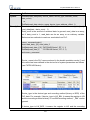
EasyBuilder8000 User’s Manual 5.1 Device
Parameters in [Device] tab determine all of the attributes of each device controlled by the
HMI they are connected with. The device can be a PLC, a remote HMI, or a PC.
After opening a new *.mtp file in EB8000, a default device: “Local HMI” is shown in the
[Device List]. This “Local HMI” is used to identify current HMI, which means, every *.mtp
file must at least contains one “Local HMI” in [Device List].
Select [Settings] under the device list, A dialogue [Device Properties] will be shown as
below. From this we know that the attribute of “Local HMI” is a “HMI” and the location is
“Local”.
Steps to add a new device:
62
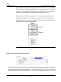
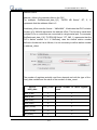
EasyBuilder8000 User’s Manual 5.1.1 How to Control a Local PLC
The so-called “local PLC” means a PLC which is connected to the local HMI directly. To
control a local PLC, users need to add this type of device first. Click [New…] under the
Device list and the [Device Properties] dialog appears. Please correctly fill in all of the
properties required.
Take a local PLC MITSUBISHI FX0n/FX2 as an example:
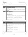
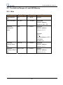
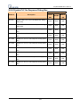
Setting
Description
Name
The name of the device set by user.
HMI or PLC
To confirm whether this connected device is a HMI or PLC. It’s [PLC]
in this example.
63
EasyBuilder8000 User’s Manual Location
[Local] or [Remote]. Showing whether this device is connected to
Local HMI or being remote controlled. Select [Local] in this case.
PLC type
Type of PLC. Select MITSUBISHI FX0n/FX2 in this case.
PLC I/F
Five PLC interfaces are available: [RS-232], [RS-485 2W], [RS-485
4W], [Ethernet], and [USB].
If the interface is [RS-232], [RS-485 2W], or [RS-485 4W], click
[Settings…] and then [Com Port Settings] dialog appears. Users
need to correctly set the COM port communication parameters.
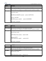
[Timeout]
If the communication between PLC and HMI is disconnected over the
set time limit in [Timeout] parameter, a pop out window No. 5 will be
shown in HMI as an alert saying “PLC No Response”.
[Turn around delay]
While sending the next command to PLC, HMI will delay it obeying
the set time interval in [Turn around delay] parameter. This may
influence the efficiency of the communication between HMI and PLC.
If no specific request to be made, “0” is to be set.
If the PLC used is in SIEMENS S7-200 Series, this parameter needs
to be set to “5” and [Parameter 1] “30”.
If the interface is [Ethernet], click [Settings…] and then [IP Address
64
EasyBuilder8000 User’s Manual Settings] dialogue appears. Users need to correctly set IP address
and Port no. of the PLC.
If the interface is [USB], no further settings need to be done. Please
check if all the settings in [Device Properties] are correct.
PLC default
station no.
PLC should be set with a read address alone with a station no. for
HMI to locate and communicate with it. If this address does not
include a station no. EB8000 will use this [PLC default station no.]
as the station no. of PLC.
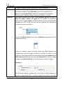
In addition, station no. can be set in the read address of PLC directly.
Take address 1#20 as an example.
“1” means PLC station no, and has to be named from 0 to 255.
“20” means PLC address, the “#” sign is used to separate station no.
and address.
Default station
no. use station
no. variable
When setting PLC properties, station no. variables can be selected
and used as [PLC default station no.]. LW10000~LW10015 can be
used to set station no. variables.
When using this function, if the station no. is not specified for PLC
65
EasyBuilder8000 User’s Manual address, it will be decided by the station no. variable of default station
no. In this example var3 is set for default station no. The following
demonstrates how the PLC address station no. is set.
a. The station number of PLC is “5”.
b. The PLC station no. is decided by var7 (LW-10007)
c. PLC address is set to “111”, since PLC station no. is not specified,
and the default station no. is using var3, the PLC station no. is
decided by var3 (LW-10003).
Use broadcast
command
This is for setting the station no. of broadcast command. Command
for the users of this set station no. will be seen as broadcast
command. For example, if the broadcast station number is set as
255, HMI with an address such as 255#200, will send this command
to all the PLC connected to it, but will ignore the replies of PLC after
receiving this command. (This only works on Modbus).
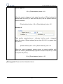
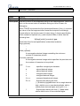
Interval of
block pack
(words)
If the interval between read addresses of different commands is less
than this value, these commands can be combined to one. But
combining function is disabled if this value is “0”.
For example, the interval value is set as “5” and users would like to
read out 1 word from LW3 and 2 words from LW6 respectively.
(Means to read from LW6 to LW7). Since the interval of addresses
between LW3 and LW6 is less than 5, these two commands can be
combined to one. The contents of combination therefore become 5
consecutive words from LW3 (read from LW3~LW7).
Note: Maximum command combination data size must be less than
[Max. read-command size].
Max.
The Max. data size to be read out from device at one time. Unit: word
66
EasyBuilder8000 User’s Manual read-command
size (words)
The Max. data size to be written to device at one time. Unit: word.
Max.
write-command
size (words)
After all settings are completed, a new device named “Local PLC 1” is added to the
[Device list].
67
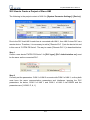
EasyBuilder8000 User’s Manual 5.1.2 How to Control a Remote PLC
The so -called “remote PLC” means a PLC connected to a remote HMI. To control a
remote PLC, users need to add this type of device. Click [New…] under [Device list] and
the [Device Properties] dialog appears. Users need to set all the required properties
correctly.
Here take a remote PLC, SIEMENS S7/200, as an example:
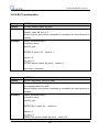
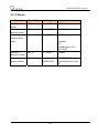
Setting
Description
68
EasyBuilder8000 User’s Manual HMI or PLC
This is to confirm whether this device is a HMI or PLC.
It is [PLC] in this case.
Location
Users can select [Local] or [Remote]. Select [Remote] in this case
and set the IP address of the remote HMI which is connected to
SIEMENS S7/200 PLC. Click [Settings…] of [Location] to set this IP
address.
PLC Type
Type of PLC. Select SIEMENS S7/200 in this case.
PLC I/F
This setting defines which interface the remote PLC uses. If the
remote PLC uses a COM port, interface used should be selected from
[RS-232], [RS-485 2W], and [RS485 4W].
PLC default
station no.
This setting defines which default station no. is used by remote PLC.
COM
This setting defines which COM port the remote PLC uses to connect
with remote HMI. The settings should be correct.
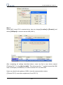
After all settings are completed, a new device named “Remote PLC” is added to the
[Device list].
69
EasyBuilder8000 User’s Manual 5.1.3 How to Control a Remote HMI
The so-called “remote HMI” means through network, this HMI is controlled by a local HMI
or a PC running on-line simulation. To control a remote HMI, users need to add this type of
device. Click [New…] under [Device list] and the [Device Properties] dialog appears.
Users need to set all the required properties correctly.
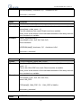
Setting
HMI or PLC
Description
This is to confirm whether this device is a HMI or PLC.
It is [HMI] in this case.
Location
Users can select [Local] or [Remote]. Select [Remote] in this case
and set the [IP address] and [Port no.] of the remote HMI. Click
[Settings…] of [Location] to set these, the dialogue is shown below.
70
EasyBuilder8000 User’s Manual The [Port no.] of remote HMI can be seen in [Model] in [System
parameters] once the* .mtp file of remote HMI is opened. The port
no. of remote HMI and local HMI must be the same.
After all settings are completed, a new device named “Remote HMI” is added to the
[Device list].
71
EasyBuilder8000 User’s Manual 5.2 Model
Parameters in [Model] tab determine the HMI model, [Timer] and [Printer] settings.
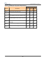
Setting
HMI model
Description
Select current HMI model as shown below.
When changing HMI model and press [OK], users will be inquired if
72
EasyBuilder8000 User’s Manual they would like to [Resize pop-up windows or objects].
HMI station
no.
Set the [HMI station no.] used by current HMI. If no specific request is
to be made, just use the default number.
Port no.
Set the [Port no.] used by current HMI. It is used as port no. of
MODBUS server. If no specific request is to be made, just use the
default number.
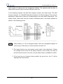
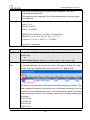
Timer
[Clock source]
To set up the signal for timer object. The time information of timer is
used by [Data Sampling], [Event Log] ….etc. which are objects that
need the time records.
a. [HMI RTC] means the time signal comes from internal clock of the
HMI.
b. [External device] means the time signal comes from external
device. To correctly set source address of time signal is necessary.
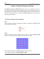
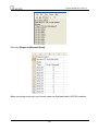
Take the illustration below as an example: It indicates the source of
time signal is from “TV” of the “Local PLC”. The source address “TV”
starts from address 0 contains 6 consecutive words and each of them
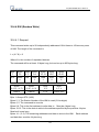
contains the following information:
TV
TV
TV
TV
TV
TV
0
1
2
3
4
5
→
→
→
→
→
→
Second (the limited range: 0~59)
Minute (the limited range: 0~59)
Hour (the limited range: 0~23)
Day (the limited range: 1~31)
Month (the limited range: 1~12)
Year (the limit range: 1970~2037)
73
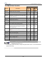
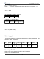
EasyBuilder8000 User’s Manual Printer
[Type]
Display printers supported. For HP PCL Series, it has to be connected
through USB interface while other printers through COM port. For more
information, please refer to “Chapter 23 Printer Types supported by
MT8000”.
Using [COM] port to connect printer, users should set accurate
parameters. When the type of printer is [SP-M, D, E, F], the [pixels of
width] has to be set accurately, i.e. the set pixel(s) can not exceed
printer’s default setting. Otherwise this printing won’t succeed.
Storage
space
1. Storage space available for the project and history data is 12MB. By
adjusting the space of these two parts, users can reach their
74
EasyBuilder8000 User’s Manual management
( For T series
only)
memory requirements, for example, using smaller sized project to
get bigger memory space for historical data. It works contrariwise.
2. Minimum Project size is 6MB; Maximum Project size is 10 MB
(default is 8MB). Minimum Historical data size is 2MB; Maximum
Historical data size is 6 MB (default is 4MB).
3. For adjusting storage space, users should erase history data saved
in HMI before downloading project file.
75
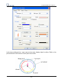
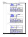
EasyBuilder8000 User’s Manual 5.3 General
Parameters in [General] tab determine all properties related to screen display.
Setting
Fast
selection
button
Description
Setting all the attributes for fast selection button that is designated as
window number 3.
a. [Attribute]
76
EasyBuilder8000 User’s Manual Enable or disable fast selection window. Select [Enable] and click
[Settings…] to set the attributes, including color and text.
b. [Position]
Select the position on the screen of HMI where this button appears. If
[Left] is chosen, the button will show up on screen bottom-left; if [Right]
is chosen, the button will show up on screen bottom-right.
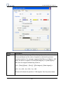
Screen
saver
a. [Back light saver]
If the screen is left untouched and reaches the time limit set here, back
light will be off. The setting unit is minute. Back light will be on again once
the screen is touched. If [none] is set, the back light will always be on
while using.
b. [Screen saver]
If the screen is left untouched and reaches the time limit set here. The
current screen will automatically switch to a window assigned in [Saver
window no.].The setting unit is minute. If [none] is set, this function is
disabled.
c. [Saver window no.]
To assign a window for screen saver.
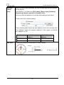
Option
a. [Startup window no.]
Designate the window shown when start up HMI.
b. [Common window]
The objects in the common window (window 4) will be shown in each
base window. This selection determines the layers these objects are
placed above or below the objects in the base window.
c. [Keyboard caret color]
77
EasyBuilder8000 User’s Manual Set the color of caret that appears when inputting in [Numeric Input] and
[Word Input] objects.
d. [Object layout]
If [Control] mode is selected, when operating HMI, [Animation] and
[Moving Shape] objects will be displayed above other kinds of objects
neglecting the sequence that the objects are created. If [Nature] mode is
selected, the display will follow the sequence that the objects are
created, first created be displayed first.
e. [RW_A enabled]
Enable or disable recipe data RW_A. Enable this, the objects can then
control the content of RW_A .The size of RW_A is 64K.
Event
[Extra no. of events]
The default number of the event in the system is 1000. If users would like
to add more records, the setting value can be modified up to 10000.
Keyboard
Users can select to use different types of keyboards for [Numeric Input]
and [Word Input]. Up to 32 keyboards can be added. If users want to
design their own keyboard, a window should be designated for creating
it. Press [add] after creating, and add the window to the list. For more
information, please see “Chapter 12 Key Pad Design and Usage” where
also shows how to fix this keyboard in screen instead of adding it to the
list.
User’s project can be restrained and executed on specific HMI (only for i
Project
protection (i series HMI). Please refer to “Chapter 30 Project protection” for more
series only) information.
78
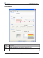
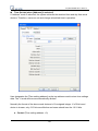
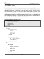
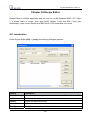
EasyBuilder8000 User’s Manual 5.4 System Setting
Parameters in [System Setting] tab are for setting up some miscellaneous functions of
EasyBuilder.
Some functions are duplicated from system tag, such as [Disable buzzer (LB-9019)], [Hide
system setting bar (LB-9020)], [Hide mouse cursor (LB-9018)], [Disable upload function
(LB-9033)], and [Prohibit remote HMI connecting this machine (LB-9044)]. It means that
79
EasyBuilder8000 User’s Manual user can also operate these functions via system tag. To select a system tag, users can
tick [system tag] of the [address] while adding new object. To check all the system tags,
users can visit [Library] in EB8000, select [Tag] then [System].
[Startup language after redownloading the project]
Set the language to use when start up HMI after redownloading the project.
[Execute init. Macro when power on]
Designate the macro to be executed when HMI power on.
[Auto logout]
If HMI is left unused for longer than the time set here, HMI will logout automatically.
[Use a disconnection icon on relative objects when PLC communication fails]
When using this function and fail to communicate with PLC, this icon will be shown in the
lower right corner of the object as shown:
The disconnection icon:
When using this function and fail to communicate with PLC, this icon will be shown in the
lower right corner of the object as shown:
[VNC Server]
Set the login password for VNC server.
[LW protection], [RW protection]
80
EasyBuilder8000 User’s Manual If users check [Disable LW/RW remote-write] and set the protect range in [LW/RW
range], values of this protected range can’t be adjusted via remote HMI.
[Easy Access server]
Through this technology, users can easily access to any MT8000i/X connected to the
internet and operate them on PC just like holding touch screen in hand.
Unlike most server used in HMI, Easy Access don’t need to transmit updated graphic
image but real time data only. This makes transmission really quick and efficient.
For further information, please refer to “EasyAccess”.
81
EasyBuilder8000 User’s Manual 5.5 Security
Parameters in [Security] tab determine the classes accessible for each user to adjust the
objects, and users’ password. The security classes of objects are classified from [A~F],
and [none] for not ticking any class. Up to twelve passwords can be set. Only numeral
setting is acceptable for password and the range is 0~999999999.
According to the security setting, EB8000 will control the classes accessible for each user
to adjust the objects once they input their passwords.
In EB8000, while constructing a project, the security classes of objects are classified from
[A~F], and [None] and can be set as shown below.
If [None] is set, every user can access to adjust this object.
82
EasyBuilder8000 User’s Manual For example, when the security class of User1 is set as below, only objects with class A, C,
E and “none” can the user adjust. For more information, please see “Chapter 10 Security
of Objects”.
[Project password (MTP file)]
Users can set password to protect the MTP file in [System parameter] / [Security tab].
Users have to input the password set here when they want to edit the MTP file.
(MTP password range: 1~4294967295)
Tick [Enable] then click [Setting], and the window is as shown below.
Before editing project, a pop-up window will ask password for access the project.
83
EasyBuilder8000 User’s Manual MTP files are protected by additional encryption, please follow the steps below:
a. EB8000 V440 or later can open old version EB8000 projects using the password
originally set in old version EB8000.
b. The old version EB8000 can’t open the projects that are built in EB8000 V440 or later
which are protected by password, if necessary, please disable (don’t tick [Enable]) the
password first.
84
EasyBuilder8000 User’s Manual 5.6 Font
Parameters in [Font] tab determine the font of non-ASCII which is used in EB8000.
[Fonts for non- strings]
Fonts for non-ASCII strings are listed above. When users use non-ASCII character set or
double byte character set ( including simplified or traditional Chinese character, Japanese,
or Korean) which is not listed in [Fonts for non-ASCII strings] table, EB8000 will select a
font from the list to substitute for it automatically.
Users can also test which non-ASCII strings of Windows can be used in EB8000 and add
them to [Fonts for non-ASCII strings] table.
[Line spacing]
Decide the interval between lines in the text.
85
EasyBuilder8000 User’s Manual 86
EasyBuilder8000 User’s Manual 5.7 Extended Memory
Parameters in [Extended Memory] tab determine the path of the extended memory.
Extended Memory is numbered from EM0 to EM9. Method to use extended memory is
similar to that of other device type (i.e. LW or RW address). Users can simply select from
[Device type] list while adding a new object. Size of each extended memory is up to 2G
word.
87
EasyBuilder8000 User’s Manual Data in extended memory is stored in [SD card], [USB1], or [USB2] in a form of a file. The
files in extended memory [EM0] ~ [EM9] are entitled as em0.emi~em9.emi. Users can use
RecipeEditor.exe to open the file and edit the data in the extended memory.
Data in extended memory will not be erased when power is cut, which means next time
when user start HMI again, data in extended memory remains just the same before power
off. This is similar to Recipe data (EW, RW_A). What is different is that users can select
where they want to save the data (SD card, USB1 or USB2)
To read data in extended memory from a removed device, the content of data will be
viewed as “0”; if users would like to write data to a removed device, the "PLC no response"
message will appear in HMI.
EB8000 supports "hot swapping" function for SD card and USB devices. Users can insert
or remove the device for extended memory without cutting the power. With this function,
users can update or take data in extended memory.
88
EasyBuilder8000 User’s Manual 5.8 Printer/Backup Server
Parameters in [Printer/Backup Server] tab are for setting up MT remote printer.
Setting
Output settings
Description
[Orientation]
Set how will words or pictures be printed out, [horizontal] or
[vertical].
[Printer size]
Set to print out in original size or to fit the set printer margins.
[Margin]
Set the top, bottom, right and left margin width.
Communication
settings
[IP address]
Assign the IP address of a remote printer via network.
89
EasyBuilder8000 User’s Manual [Port], [User name], [Password]
Assign the access information.
Port can be set from 1 to 65535.
Maximum length of user name or password is 12 characters.
※ Please refer “Chapter 26 Easy Printer” for more information.
90
EasyBuilder8000 User’s Manual Chapter 6 Window Operations
The basic component of a HMI screen is a Window, This shows its importance. With a
window, all kinds of information like objects, pictures, and words can be shown in HMI
screen. Generally, there’s more than one window in a project, many windows will be
constructed in one project. Users are able to configure 1997 windows or screens
numbered from 3~1999 in EB8000. For how many windows can be used in one project, it
depends on the storage size for windows of HMI. For example, the storage size of MT8000
i series for windows is 16MB, then the size of windows or screens constructed cannot
exceed 16MB. Under this limit users can make most use of it to create as many windows
as possible.
6.1 Window Types
There are 4 types of windows in EB8000 each with different functions and usages.
a. Base Window
b. Common Window
c. Fast Selection Window
d. System Message Window
6.1.1 Base Window
Base window is the most frequently-used type of window.
Apart from being used as main screen, it is also used as:
a. Foundation base: used as the background for other windows
b. Keyboard window
c. Pop-up window for [function key] object
d. Pop-up window for [direct window] and [indirect window] object
e. Screen saver
91
EasyBuilder8000 User’s Manual Base window should be in the same size as the HMI screen. That is to say, the resolution
of base window and that of HMI should be identical.
The start up screen is a base window and is shown below:
6.1.2 Common Window
Window no. 4 is the default common window. Objects in this window will be displayed in
other base windows, but it does not include popup window. Therefore, objects in different
windows, whether shared or same, will be placed in common window, for example, the
logo of the product, or a common button. When system is in operation, Clicking [Function
Key] and selecting [Change common window] allow users to change the source of
common window. For example, users can change the common window from window 4 to
window 20.
92
EasyBuilder8000 User’s Manual 6.1.3 Fast Selection Window
Window no. 3 is defined as the Fast Selection Window. This window can coexist with base
window. Generally speaking, it is used to place the frequently-used operation buttons as
the picture below:
When using Fast Selection Window, window no. 3 should be created first, and then users
need to set each function of Fast Selection button. The [Fast Sel] button in the picture
above is the Fast Selection button, which is used to Enable/Disable Fast Selection window
93
EasyBuilder8000 User’s Manual control. Every setting of the [Fast Selection button] is in [System Parameter Settings].
Please refer to the dialog below.
Apart from Enable/Disable Fast Selection window by Fast Selection button, system
register also provides the following addresses for users to Enable/Disable certain
functions in order to control fast selection window/button. The related registers are listed
below. Please refer to “Chapter 22 system reserved words and bits” for more details.
[LB-9013] FS window control [Enable (open) / Disable (close)]
[LB-9014] FS button control [Enable (open) / Disable (close)]
[LB-9015] FS window / button control [Enable (open) / Disable (close)]
6.1.4 System Message Window
Window no. 5~8 are the defaults of system message windows.
Window
Description
Window no. 5 is the “PLC
Response” message
window
When the communication between PLC and HMI is
disconnected, this message window will pop up
automatically right on the window opened previously.
Window 6 is the “HMI
connection” message
window
When failing to connect with remote HMI, this message
window will pop up automatically.
Window 7 is the “Password
Restriction” message
window
If user wants to control an object without authorization,
this window may pop up as an alert or not depending on
how this object is set originally.
94
EasyBuilder8000 User’s Manual Window 8 is the “Storage
Space Insufficient”
message window
When HMI built-in memory, USB disk or SD card run out
of storage space, this message window will pop up
automatically.
Users can use system address tag to view the free
memory space in HMI, USB disk, or SD card device.
[LW-9072] HMI current free space (K bytes)
[LW-9074] SD current free space (K bytes)
[LW-9076] USB 1 current free space (K bytes)
[LW-9078] USB 2 current free space (K bytes)
For checking which device is insufficient in space while
this insufficiency occurs, the following system address
tags can be used.
[LB-9035] HMI free space insufficiency alarm (when ON)
[LB-9036] SD free space insufficiency alarm (when ON)
[LB-9037] USB 1 free space insufficiency alarm (when
ON)
[LB-9038] USB 2 free space insufficiency alarm (when
ON)
The text shown in window no. 5~8 can be adjusted by users to fit what is needed. For
example, text in window no. 5 is “PLC No Response”, users can change it to “HMI and
PLC disconnected!” This works for other windows as well, which makes it easier to read.
Note:
(1) A screen can display 16 pop-up windows simultaneously in maximum including System
Message Window, Direct window and Indirect window.
(2) A window can only be displayed once simultaneously. That is to say, users cannot use
2 Direct (Indirect) windows to open the same window in one base window at the same
time.
(3) Windows 0~9 are for system use only while windows 10~1999 are for users to define.
95
EasyBuilder8000 User’s Manual 6.2 Create, Set, and Delete a Window
The picture below shows the windows information (window tree) in EB8000. This window
is always shown on left side of the editing zone. There are 2 ways to check all types of
windows in EB 8000. If users change [Object List] to [Window Preview], every window
will be shown in pictures. The following section introduces how to create and set these
windows.
6.2.1 Create a Window
There are two ways to create a window:
One is to select a window number in window tree and right click, then select [New].
Complete all the settings in the pop-up dialogue and click [OK] as shown below:
96
EasyBuilder8000 User’s Manual Setting
Description
Name
The name shown after window is numbered.
The principle is to make it easy to read and be remembered. For
example: “Operate Manually” etc.
Window no.
Number of window. Numbered from 3~1999.
Size
[Width] and [Height] of the window. Generally, the resolution of base
window and that of HMI is identical. For example, if the HMI used is
MT6100i, the resolution is 800 * 480. Then the newly built window width
will be 800 and height 480.
Frame
The [Width] of the frame of the window. Range from 0~16, the default is
“4”.
97
EasyBuilder8000 User’s Manual The [Color] of the frame of the window. Users can select a color they like
from the list, or simply click [Custom…] to adjust a self-defined color. If
the Width of the frame is set “0”, then this setting will be ignored.
Background [Color]
The color of the background of the window.
[Pattern]
The pattern of the background of the window. If needed, users can
choose a pattern they like from [pattern style] that pops up after clicking
button of the pattern.
[Pattern color]
The color of the pattern.
[Filled]
Tick to determine if a window is filled with the color and pattern set for the
background
Underlay
window
[Bottom], [Middle], [Top]
Up to three base windows can be specified as underlay windows for
each base window, from [Bottom] to [Top]. The objects (but not the
backgrounds) in underlay windows are displayed in this order in base
window.
Popup
window
[X], [Y]
Base window can also be used as pop-up window. Use [X] and [Y] to set
the coordinates indicate where in the screen will this base window pop
98
EasyBuilder8000 User’s Manual up. The origin of the coordinates is the left-top corner of the screen.
[Monopoly]
If the option is checked, when a base window used as a pop-up window
appears, users are not allowed to operate other windows before this
base window is closed. If a base window is used as a keyboard window,
“Monopoly" is automatically enabled.
Another way to create a window is to select [Window] from menu in EB8000 and then
select [Open Window] to open the dialogue. Please refer to the illustration below.
Window No., Window Name and Size are listed in the [Open Window] dialogue.
Click [New…] and choose window type from [Select Window Style] dialog. Complete all
the settings and click [OK], a new window is created.
99
EasyBuilder8000 User’s Manual Once the base window is built, its window number sticks with it and can’t be changed. But
the size, color, and name of the window can still be modified.
6.2.2 Window Settings
EB8000 provides three methods to modify window attributes:
a. Right click on the designated window from window tree and select [Settings] to open
the [Window Settings] dialogue to change the window properties.
b. Right click directly in the window without selecting any object and then select [Attribute].
Or, click
in EB8000 menu without selecting any object can also open the [Window
Settings] dialogue.
100
EasyBuilder8000 User’s Manual c. Select [Window] from menu in EB8000 and select [Open Window], a dialogue appears.
Designate a window to modify then choose [Settings] to open the [Window Settings]
dialogue.
6.2.3 Open, Close and Delete a Window
To open an existing window, not only double click the window No. from the window tree,
users can also right click the assigned window from the window tree and choose [Open] to
open it.
Similarly, to close or to delete an existing window is same as the procedure above .Please
note that the window to be deleted has to be closed. That is to say, only a closed window
can be deleted.
101
EasyBuilder8000 User’s Manual Chapter 7 Event Log
“Event log” is used to define the content of an event and the conditions triggering it. In
EB8000, this triggered event, also called “alarm”, and its processing procedure can be
saved to designated places such as HMI memory storage or external memory device. The
saved file is with a name in a format as EL yyyymmdd.evt. In this name, yyyymmdd
records the time that this file is built, and will be set automatically by the system. Take file
name EL_20100524.evt as an example, this shows that this created file records the event
occurred on 24th of May, 2010.
EB8000 also provides the following system address tags to manage the event log:
Address
Description
LB-9021
reset current event log (set ON)
LB-9022
delete the earliest event log file on HMI memory (set ON)
LB-9023
delete all event log files on HMI memory (set ON)
LB-9024
refresh event log information on HMI memory (set ON)
LB-9034
save event/data sampling to HMI, USB disk, SD card (set ON)
LB-9042
acknowledge all alarm events (set ON)
LB-9043
unacknowledged events exist (when ON)
LB-11940
delete the earliest event log file on SD card (set ON)
LB-11941
delete all event log files on SD card (set ON)
LB-11942
refresh event log information on SD card (set ON)
LB-11943
delete the earliest event log file on USB 1 (set ON)
LB-11944
delete all event log files on USB 1 (set ON)
LB-11945
refresh event log information on USB 1 (set ON)
LB-11946
delete the earliest event log file on USB 2 (set ON)
LB-11947
delete all event log files on USB 2 (set ON)ON)
LB-11948
refresh event log information on USB 2 (set ON)
LW-9060
(16bit) : no. of event log files on HMI memory
LW-9061
(32bit) : size of event log files on HMI memory
LW-9450
(16bit) : time tag of event log - second
LW-9451
(16bit) : time tag of event log - minute
LW-9452
(16bit) : time tag of event log - hour
LW-9453
(16bit) : time tag of event log - day
102
EasyBuilder8000 User’s Manual LW-9454
(16bit) : time tag of event log - month
LW-9455
(16bit) : time tag of event log - year
LW-10480
(16bit) : no. of event log files on SD card
LW-10481
(32bit) : size of event log files on SD card
LW-10483
(16bit) : no. of event log files on USB 1
LW-10484
(32bit) : size of event log files on USB 1
LW-10486
(16bit) : no. of event log files on USB 2
LW-10487
(32bit) : size of event log files on USB 2
103
EasyBuilder8000 User’s Manual 7.1 Event Log Management
With objects like [Alarm Bar], [Alarm Display] and [Event Display], users are able to clearly
understand the life cycle of the whole event from happening, waiting for processing, until
the alarm stops. Before using these objects, the content of an event has to be defined first.
Click the [Alarm (Event Log)] icon, and the dialog appears as below:
104
EasyBuilder8000 User’s Manual Setting
Description
Category
EB8000 classifies events. All events are divided into categories 0~255.
[Alarm Bar], [Alarm Display], and [Event Display] can be used to restrain
which category to display.
[Category] is for selecting which category of the events to be displayed.
The [2] of 0[2] in this illustration demonstrates there are two defined events in
category 0.
History
files
Determine the storage device of an event log. However, when users simulate
the project in PC, the files will be saved under the same event log
subdirectory as EasyBuilder8000.exe.
[Save to HMI memory]
Save the event log data in MT8000 memory.
[Save to SD card]
Save the event log data in SD card.
[Save to USB 1]
Save the event log data in USB disk 1. Numbering rule of USB disk is: the
disk inserted to the USB interface in the first place is numbered 1, next is
numbered 2 and the last is numbered 3. It is not related to the interface
position.
[Save to USB 2]
Save the event log data in USB disk 2.
[Preservation limit]
After choosing the device to save the Event log, users can see the
105
EasyBuilder8000 User’s Manual [Preservation limit] selection. This setting determines how many days the
data to be preserved.
For example, the preservation time is set two days, which means HMI
memory will keep the data of yesterday and the day before yesterday. Data
that is not built in this period will be deleted automatically to prevent the
storage space from running out.
Print
To enable this setting, users have to finish the settings of printer in [system
parameter settings].
7.1.1 Excel Editing
There is an Excel icon in the top-right corner of the [Alarm (Event Log) dialog] for users
to edit an Event log through Excel. An editing procedure includes: Edit in Excel, Import
from Excel to Event Log and Export to Excel.
A. Edit in Excel
EB8000 provides a standardized sample of Excel in C:\EB8000\EventLogExample.xls for
users to edit alarm (event) log. The sample includes some dropdown lists for an easier
usage
106
EasyBuilder8000 User’s Manual Caution:
1. [System tag] and [User-defined tag] can not be set true simultaneously. If both of
them are set true, the system will view System tag to be true and User-defined tag to
be false. If Device type is set as User-defined tag, please set System tag to be false.
2.
The format of Color is R: G: B. the values of R, G, and B should be integer from 0 to
255.
3.
Click Excel icon to open EventLogExample.xls
B. Import from Excel to Event log
Click [Import excel button] to import Excel file to Event log.
107
EasyBuilder8000 User’s Manual Caution:
1. When user-defined tag is set true in Excel, the system will compare this device type with
the user-defined tag in system. If no suitable tag can be found, the system will set the
user defined tag in event log to be false.
2. Before importing library (label library and sound library), please make sure library
names exist in the system, otherwise the system will simply use the file name of the
imported excel file.
C. Export to Excel
Click [Export excel button] to export data in Event log to excel.
108
EasyBuilder8000 User’s Manual 109
EasyBuilder8000 User’s Manual 7.2 Create a New Event Log
Click [New…]; [Event Log] dialog appears with two tabs.
[General] tab:
Setting
Description
Category
The category of an event.
Priority level The priority of an event: Users can define [Low], [Middle], [High], or
[Emergency] according to the importance of the event. When the
number of event log equals to the max number available in the system,
the less important events (lower priority) will be deleted and new events
will be added in. (the default is 1000, please refer to “General” in
“Chapter 5 System Parameters” to set this number)
Address
type
The type of address—[Bit] or [Word] mode.
Read
address
By reading the address set here, system obtains a value and will use it to
check if an event reaches the condition to be triggered. Please refer to
110
EasyBuilder8000 User’s Manual “Chapter 9 Object General Properties” for more information.
Notification
When an event is triggered, the specific message is sent out from
Notification address. Select [Set ON] to send ON message to this
address or select [Set OFF] to send OFF message to this address.
Please refer to “Chapter 9 Object General Properties” for detail.
Condition
The trigger condition of an event. When [Address type] of an event is
[Bit], then [ON] or [OFF] in [Trigger] can be selected. The illustration
below shows if Trigger [ON] is selected, and the status of [Read address]
changes from OFF to ON, an event will be triggered and generate an
event log record (or an alarm).
When the [Address type] of an event is [Word], several selections are
available as follows:
Under the condition, system will read values from [Read address] and
compare them with the trigger conditions to decide if an event is to be
triggered. If the trigger condition is set as [==] or [<>], [In tolerance] and
[Out tolerance] need be set while [In tolerance] is used as trigger
condition and [Out tolerance] is used as system’s normal condition.
Example 1:
The illustration above indicates that if the value of [Read address] is
greater or equal to 29(=30-1), or less or equal to 31(=30+1), the event
111
EasyBuilder8000 User’s Manual will be triggered.
29 <= [Read address] value <=31
After the event is triggered, only when the value of [Read address] is
greater than 32(=30+2) or less than 28(=30-2) will the system return to
normal condition.
[Read address] value < 28 or [Read address] value >32
Example 2:
Take another example above, it indicates that the event is triggered
when the value of [Read address] is less than 29(=30-1) or greater than
31(=30+1).
[Read address] value <29 or [Read address] value >31
When the event is triggered, system returns to normal condition only
when the value of [Read address] is greater or equal to 28(=30-2), or less
or equal to 32(=30+2).
28 <= [Read address] value <= 32
[Message] tab: Please see the illustration below
112
EasyBuilder8000 User’s Manual Setting
Description
Text
[Content]
The text content of event log shown in [Alarm Bar], [Alarm Display]
and [Event Display]. Please refer to “Chapter 9 Object General
Properties” for more information.
The data of LW address of the triggered event can be included in
the content.
Format: %#d
113
EasyBuilder8000 User’s Manual %: initial sign
# : LW’s address
d : end sign
For example, if the content is set as “High Temperature = %20d”,
when an event is triggered, the value of LW20 will be displayed.
If the value of LW20 is 13 when an event is triggered, the content
displayed in [Event Display] object will be “High Temperature = 13”.
Except for LW, when an event is triggered, data in certain device
type can also be shown in the content. This device type should be
the same as that of the [read address] of event log.
Format: $#d
$: initial sign
# : PLC’s address
d : end sign
For example, if Device type in Read address is MW, when content
is set as “High Temperature = $15d” and the value in MW15 is 42
while the event is triggered, the displayed content in [Event Display]
will be “High Temperature = 42”.
[Font], [Color]
Users can set Font and Color for each event. The font and color of
an [alarm display] or [event display] object comes from this setting.
As illustration below, these two events use different colors and font
styles.
Write value for
Event Display
object
When an event item in an [event display] object is touched, the
value is written to the assigned address. Please refer to “Chapter 13
Objects” for information about [event display] object.
Sound
The warning alarm used when an event is triggered can be
selected.
Click [Sound Library] to choose warning sound, and click [Play] to
114
EasyBuilder8000 User’s Manual check the sound.
[Enable continuous beep until acknowledged or recovered]
Continuous beep can be set which will only stop when the event is
acknowledged or recovered. (System register [LB-9042] can be set
to acknowledge all alarm events at one time.) The system default
[Beep] sound is used as this continuous beep.
When using continuous beep for Event Log, a delay period can be
set between triggering the alarm and the start of beeping.
An illustration of how the beep is related to the event:
When exporting Event Log as EXCEL file, next to the content of
[Watch Address], the related settings of the continuous beep can be
found. Address of Watch
User can use the [Syntax] to embed PLC data in the content of an
event log.
About the syntax usage, please refer to below dialog.
115
EasyBuilder8000 User’s Manual 116
EasyBuilder8000 User’s Manual Chapter 8 Data Sampling
“Data Sampling” defines how the data is sampled, including sampling time and sampling
address. EB8000 saves the sampled data to the user assigned location.
The directory of saved data: [Storage location]\[filename]\yyyymmdd.dtl
[Storage location] can be HMI, SD (CF) card, USB1 or USB2 which is designated by
users.
[Filename] is usually a name defined by user. This name can’t be used repeatedly by
other sampled data files.
yyyymmdd shows when the file is built and is set by the system automatically.
EB8000 provides the following system registers for data sampling management:
Address
Description
LB-9025
delete the earliest data sampling file on HMI memory (set ON)
LB-9026
delete all data sampling files on HMI memory (set ON)
LB-9027
refresh data sampling information on HMI memory (set ON)
LB-9034
save event/data sampling to HMI, USB disk, SD card (set ON)
LB-11949
delete the earliest data sampling file on SD card (set ON)
LB-11950
delete all data sampling files on SD card (set ON)
LB-11951
refresh data sampling information on SD card (set ON)
LB-11952
delete the earliest data sampling file on USB 1 (set ON)
LB-11953
delete all data sampling files on USB 1 (set ON)
LB-11954
refresh data sampling information on USB 1 (set ON)
LB-11955
delete the earliest data sampling file on USB 2 (set ON)
LB-11956
delete all data sampling files on USB 2 (set ON)
LB-11957
refresh data sampling information on USB 2 (set ON)
LW-9063
(16bit) : no. of data sampling files on HMI memory
LW-9064
(32bit) : size of data sampling files on HMI memory
LW-10489
(16bit) : no. of data sampling files on SD card
LW-10490
(32bit) : size of data sampling files on SD card
LW-10492
(16bit) : no. of data sampling files on USB 1
LW-10493
(32bit) : size of data sampling files on USB 1
LW-10495
(16bit) : no. of data sampling files on USB 2
LW-10496
(32bit) : size of data sampling files on USB 2
117
EasyBuilder8000 User’s Manual 118
EasyBuilder8000 User’s Manual 8.1 Data Sampling Management
Before using [Trend display] or [History data display] objects to review the content of data
sampling, the method of how the data is sampled has to be defined. Click [Data Sampling]
on the toolbar and then [Data Sampling Object] dialog appears as below.
Setting
Description
New
Add a new “data sampling” definition.
Delete
Delete a specific “data sampling” definition.
Settings
Modify a “data sampling” definition.
119
EasyBuilder8000 User’s Manual 8.2 Create a New Data Sampling
Click [New…] and the [Data Sampling Object] setting dialog appears as below:
[Sampling mode]
EB8000 provides two methods of data sampling: [Time-based] and [Trigger-based].
If [Time-based] mode is selected, EB8000 samples the data in a fixed frequency. Users
have to set the [sampling time interval].
If [Trigger-based] mode is selected, users can use the status of specific address to trigger
the data sampling.
120
EasyBuilder8000 User’s Manual [Mode]
Conditions to trigger the data sampling:
[OFF → ON] This will trigger data sampling when the status of assigned address changes
from OFF to ON.
[ON → OFF] This will trigger data sampling when the status of assigned address changes
from ON to OFF.
[ON←→ OFF] Trigger data sampling when the status of assigned address is changed.
[Read address]
Select a device type to be the source of data sampling.
[Data Record]
[Max. data records]
Max. number of data records that can be saved by one data sampling definition in one day.
If [sampling time interval] is set as 0.1 second then the max number of data records is
86400.
1. If the data source of [trend display] is in [real-time] mode, the earlier record will be
deleted and new record will be added and displayed in the [trend display] object.
2. If the data source of [trend display] is in [historical] mode, the data will still be
sampled.
[Auto stop]
When the number of data sampling equals to [Max. data records], and the [Auto stop]
option is selected, HMI will stop sampling data automatically.
Example:
Condition
Set [Max. data records] as
10 without checking [auto.
Set [Max. data records] as 10
and check [auto. Stop]
Stop]
Trend display – real
time
The data will keep the latest
10 records in the screen
Stop displaying after reaching
10 data records.
Data sampling
Keep recording and delete
the earlier data
Stop recording after reaching
10 data records.
[Data Format]
The formats of different data in one data sampling: A data sampling may include more
than one type of records. Data sampling in EB8000 is able to retrieve different types of
121
EasyBuilder8000 User’s Manual records at the same time. Users can click [Data Format] to open the dialog to define the
content in one data sampling.
Take the following as an example, user defines three types of data: “Index” (16-bit
Unsigned), “Pressure 1” (16-bit Signed) and “Temperature” (32-bit Float) respectively,
which makes data length to be 4 words in total. In this way, EB8000 retrieves a
4-words-lengthed data each time from the assigned address to be the content in one data
sampling.
Caution:
After executing off-line simulation, if users need to change data format, please delete data
log file in C:\EB8000\***\datalog and then run off-line simulation again. The symbol “***”
means the storage location of data files.
[Clear address]
If the status of the assigned address is set ON, the obtained data will be cleared and the
number of data sampling will go back to zero. This won’t affect sampled data that is
already saved in file.
Caution: this function is used for [trend display] in [real-time] mode only.
[Hold address]
If the status of the assigned address is set ON, sampling will be paused until the status of
assigned address returns to OFF.
[History files]
Assign the storage location for data sampling. However, when users execute simulation on
PC, all data will be saved to the same subdirectory of datalog as EasyBuilder 8000.exe.
122
EasyBuilder8000 User’s Manual [Save to HMI memory]
Save the data sampling in MT8000 HMI.
Caution:
The data can only be saved when its size reaches 4kb; otherwise, users need to use
[LB-9034] to force storing this data.
[Save to SD card]
Save the data sampling in SD card.
[Save to USB 1]
Save the data sampling in USB disk no.1. Numbering rule of USB disk is: the disk inserted
to the USB interface in the first place is numbered 1, next is numbered 2 and the last is
numbered 3. It is not related to the interface position.
[Save to USB 2]
Save the data sampling to USB disk no.2.
[Folder name]
Set the file name of the data sampling. A folder name must be composed entirely of ASCII
characters!!
[Preservation limit]
This setting determines how many days the data to be preserved.
For example, the preservation time is set two days, which means USB 1 will keep the data
of yesterday and the day before yesterday. Data that is not built in this period will be
deleted automatically to prevent the storage space from running out.
If today were July 1st, the USB 1 will keep the data of June 30th and June 29th in the
memory but the data of June 28th will be deleted.
123
EasyBuilder8000 User’s Manual Chapter 9 Object General Properties
The contents of [general] properties settings of an object include:
1. Selecting the connected PLC.
2. Setting reading and writing address
3. Using shape library and picture library
4. Setting text content
5. Adjusting profile size
9.1 Selecting PLC
It is required to designate which PLC to operate while using some objects as shown below.
[PLC name] represents the controlled PLC. In this example there are 2 PLC: “Local HMI”
and “Allen-Brandley DF1.” These listed available PLC devices are sourced from [Device
List] in [System Parameters Settings].
9.1.1 Setting the Reading and Writing Address
124
EasyBuilder8000 User’s Manual The picture above shows a reading address or writing address contains:
[PLC name]
This is for selecting device type. Different PLC are with different selections of [device
type].
[Address]
Set the reading and writing address.
[System tag]
Address tag includes “system tag” and “user-defined tag.” Click [Setting…] beside [PLC
name] and tick [system tag]. This allows users to use the preserved addresses by system
for particular purpose.
These address tags are divided into bit or word (LB or LW).
After selecting [System tag] not only will the [Device type] displays the content of the
chosen tag, [Address] will also display the register chosen as shown below.
125
EasyBuilder8000 User’s Manual The illustration below shows a part of system tags. For further information, please refer
“Chapter 16 Address Tag Library” and “Chapter 22 System Reserved Words and Bits”.
[Index register]
Deciding to use Index register or not, please refer to “Chapter 11 Index Register” for more
information.
Selecting Data Type
EB 8000 supports data types that are listed below. Selecting correct data type is
necessary especially while using address tag.
126
EasyBuilder8000 User’s Manual 127
EasyBuilder8000 User’s Manual 9.2 Using Shape Library and Picture Library
[Shape Library] and [Picture Library] are used for enhancing the visual effect of an object.
For setting these, please go to [Shape] tab in the dialog for adding new object to set up
[Shape Library] and [Picture Library].
9.2.1 Settings of Shape Library
[Shape Library…]
128
EasyBuilder8000 User’s Manual Users can tick [Use shape] to enable this setting and select the shape from the library.
[Inner]
Tick [Inner] to enable this setting and select a color for inner part of the shape. Click drop
down button to open the [Color] dialogue to choose a color from the list or [customize]
their own color and click [Add to Custom Colors] for system to remember this color.
[Frame]
Tick [Frame] to enable this setting and select a [color] for the frame of the shape. The way
of setting is same as above.
[Interior Pattern]
Click to select the style of the interior pattern of the shape. The color of this pattern can
also be set.
[Pattern Style]
Click [Pattern Style] button to open the dialogue.
129
EasyBuilder8000 User’s Manual [Duplicate these attributes to every state]
Duplicate all attributes of the current state to other states.
How to set [Shape Library…]
Click [Shape Library…] button, the following dialog appears. The currently selected shape
is marked by a red frame.
130
EasyBuilder8000 User’s Manual The illustration above provides information of one of the Shapes in the Shape Library as
follows:
2: Green
The number and the name of the shape in the library.
States: 3
The number of the states of the shape. In this case, it shows the
Shape possesses three states.
Frame
Indicates that the Shape is set with “frame” only.
The illustration below shows that the Shape is set with “inner” and “frame.”
Note: About all the settings in [Shape Library], please refer to the illustrations in “Chapter
14 Shape Library and Picture Library” for details.
Click [OK] and preview the design of the shape after the setting is completed.
131
EasyBuilder8000 User’s Manual 9.2.2 Settings of Picture Library
[Picture Library]
Users can click [Use picture] to enable selecting a picture from the library.
How to set [Picture Library…]
Click [Picture Library…] button and [Picture library] dialog appears. The currently
selected picture is marked by a red frame.
132
EasyBuilder8000 User’s Manual The illustration above provides information of one of the Pictures in the Picture Library as
follows:
Picture
name
0 : PB Red The number and name of the Picture
Total states 2
The number of the states of the picture
Image size
30054
bytes
The size of the Picture
Image
format
BMP
The format and resolution of the Picture; BMP means
(100x100) bitmap Picture and its format can also be JPG, PNG, DPD,
133
EasyBuilder8000 User’s Manual or GIF. Picture Length: 100 pixels and height: 100 pixels in
this case.
Note: About all the settings in [Picture Library], please refer to the illustrations in “Chapter
14 Shape Library and Picture Library” for details.
Click [OK] and preview the design of the picture after the setting is completed.
134
EasyBuilder8000 User’s Manual 9.3 Setting Text Content
Go to [Label] tab while adding new object to set the text content as shown below.
[Use label]
Check [Use label] and click [Label Library] button to add and edit the text. EB8000
supports Windows true-font.
135
EasyBuilder8000 User’s Manual [Use label library]
Check [Use label library] to choose a label tag that exists in Label Library as shown below.
[Label Library…]
Note: About all the settings in [Label Library], please refer to the illustrations in “Chapter
15 Label Library and use Multi-Language” for details.
[Font]
Select font style from font list. EB8000 supports Windows true-font as shown below.
[Color]
Select the text color.
[Size]
Select the text size. The text sizes supported by EB8000 are listed below.
136
EasyBuilder8000 User’s Manual [Align]
Select how users would like to align the text in multiple lines
.
The text aligned [Left].
The text aligned [Center].
The text aligned [Right].
137
EasyBuilder8000 User’s Manual [Blink]
To decide how will the text blink:
Choose [None] to disable this feature or set blinking interval as [1 second] or [0.5
seconds].
[Italic]
Use Italic font.
[Underline]
Use Underline font.
[Movement] setting
[Direction]
Set the direction of the marquee effect.
[Continuous]
Whether this selection is tick or not influences how the marquee effect is displayed:
If not checking [Continuous], the next text appears only when the previous text disappears
completely. See the picture below.
138
EasyBuilder8000 User’s Manual If checking [Continuous], the text will be displayed continuously.
[Speed]
Adjust the speed of the text movement.
[Content]
Set the content of the text. If using [Label Library], the content will be sourced from Label
Library.
[Tracking]
When [Tracking] is selected, moving the text of one state will also move the text of other
states.
[Duplicate this label to other states]
This function is used to duplicate the current text content to the other states.
139
EasyBuilder8000 User’s Manual 9.4 Adjusting Profile Size
When an object is created, double click it and go to the [Profile] tab to adjust the position
and size of the object.
a. Position
Set if the position and size of the object is [Pinned]. When it is checked, the position and
size of the object cannot be changed. X and Y mean the [X] and [Y] coordinate of the
left-top corner of the object.
b. Size
Adjust the [width] and [height] of the object.
140
EasyBuilder8000 User’s Manual 9.5 Variables of Station Number
EB8000 version 1.31 or higher allows users to set variables of station number in PLC
address. As shown below, “var2” is one of 16 station number variables.
The syntax of variable of station number:
varN#address
The range of N is integer from 0~15; address means PLC address.
16 variables are availble:var0 ~ var15. These variables of station number read values
from address LW-10000~LW-10015. The list below shows variables and its corresponding
system reserved address LW:
var0
var1
var2
var3
var4
var5
var6
var7
var8
var9
var10
var11
var12
var13
var14
var15
LW-10000
LW-10001
LW-10002
LW-10003
LW-10004
LW-10005
LW-10006
LW-10007
LW-10008
LW-10009
LW-10010
LW-10011
LW-10012
LW-10013
LW-10014
LW-10015
141
EasyBuilder8000 User’s Manual For example, “var0” reads value from LW-10000, when value in LW-10000 is “32”,
var0#234 = 32#234 (the station number is 32); similarly, “var13” reads value from
LW-10013, when value in LW10013 is” 5”, var13#234 = 5#234.
142
EasyBuilder8000 User’s Manual 9.6 Broadcast Station Number
MT6000/8000 provides two ways for users to enable using broadcast command. First is to
set it directly in [system parameter settings] [Device] tab:
Second way is to use system tag to enable or disable broadcast station number or to
change it.
Corresponding system tags are listed as below:
LB-9065
LB-9066
LB-9067
disable/enable COM 1 broadcast station no.
disable/enable COM 2 broadcast station no.
disable/enable COM 3 broadcast station no.
LW-9565
LW-9566
LW-9567
COM 1 broadcast station no.
COM 2 broadcast station no.
COM 3 broadcast station no.
143
EasyBuilder8000 User’s Manual Chapter 10 Security
Security of objects in EB8000 includes two parts:
1. User password and corresponding operable classes
2. Security settings of every single object
10.1 Settings of Password and Classes
Go to [Edit]/ [System Parameter Settings]/ [Security] to set user password and
operable classes of objects.
There are seven security levels, classified from “A to F” and includes “none”.
Password should be digits from 0 to 9 and up to 12 sets of user password are available.
Once password is entered, the objects that the user can adjust are set here. For example,
when the security class of “User 1” is set as above, only objects with class “A, C, E” and
“none” can the user adjust.
144
EasyBuilder8000 User’s Manual The correct process of inputting password:
1. Input the passwords to the system reserved register [LW-9220: password] (2 Words,
32 bits).
2. Use [LW-9219: User no. (1~12)] (1 Word, 16bit) to designate current user.
Note: value in [LW-9219] must be 1~12, which represents “User 1”~”User 12” respectively.
If the input password is wrong, state of [LB-9060: password error] will be set ON;
If the input password is correct, state of [LB-9060] returns to OFF automatically.
The passwords of user 1 to user 12 can be obtained from system reserved registers
[LW-9500: user 1’s password] to [LW-9522: user 12’s password], 24 words in total.
Users can change passwords even when the HMI is in operation:
When state of system reserved register [LB-9061: update password (set ON)] switches
from OFF to ON, EB8000 will use the data saved in [LW-9500] to [LW-9522] to update the
password and use the new password in future.
Note: The user operable classes of objects won’t be changed due to the change of
password.
When the state of [LB-9050: user logout] switches from OFF to ON, current user will be
forced to logout the system. At this time, only the object defined as “None” can be
operated.
[LW-9222: classes can be operated for current user] records the operable classes
for current user:
bit0 = 1 means the operable object for current user is class “A”;
bit1=1 means the operable object for current user is class “B “and so on.
145
EasyBuilder8000 User’s Manual 10.2 Security of Objects
Setting
Description
Safety control [Safety control] is mainly used to prevent operator from
miss-operating an object accidentally. There are two methods for
protection:
[Min. press time (sec)]
Only when pressing the object continuously longer than the time set
here can an object to be activated successfully.
[Display confirmation request]
After pressing the object, a confirm dialog appears. Users need to click
146
EasyBuilder8000 User’s Manual [Yes] to confirm executing. If response to this dialog comes later than
the set [Max. waiting time (sec)], the dialog will disappear
automatically and the operation will be canceled.
Message text (The one above is “Please confirm the operation”) in the
dialogue is defined in [System Message] object and can be changed
by user. Click [System Message] icon in tool bar and the dialog
appears. Content in [Message0] is for operation confirmation.
Interlock
When this feature is applied to an object, whether or not an object is
allowed to be operated will be decided by the state of appointed bit
147
EasyBuilder8000 User’s Manual address (or called “Enable” address). ”Enable” address must be in the
form of Bit address. The content of the address is set in the following
dialog.
Fox example, suppose [Use interlock function] is checked for an
object and the “Enable” bit address is set to [LB0].The object can be
operated only when the state of [LB0] is ON. The [Interlock] feature
also provides the following settings.
[Use interlock function]
Enable/disable the interlock function.
[Hide when disabled]
When the state of Bit address of the object is OFF and [Use interlock
function] is ticked, hide the object.
[Grayed label when disabled]
When the state of Bit address of the object is OFF and [Use interlock
function] is ticked, the label of the object will be grayed.
grayed
User
restriction
normal
This function is used to set the security class of an object. Only when
user’s permitted security class meets the object’s can it be operated.
When [Object class] is selected as [None], any user with any security
class can operate this object. The following settings are also provided
in the function:
[Disable protection permanently after initial activation]
Once the permitted security class of the user meets that of the object,
the system will stop checking the security class when operating this
148
EasyBuilder8000 User’s Manual object permanently. Which means even if the user is changed this
object can still be operated freely.
[Display warning message if access denied]
When the user’s current security level does not meet that of the object,
a warning dialog appears.
Window 7 is set as an alert message for authority security. Users can
design the content of the message.
[Make invisible while protected]
When a user’s security level does not meet that of the object, the
object will be hidden.
Sound
Each object can be set whether to use the beeper to make a specific
sound or not. A system register [LB9019] is used as the switch of the
beeper. When state of [LB9019] is OFF, beeper is enabled. If restart
HMI, the settings of beeper stay the same.
149
EasyBuilder8000 User’s Manual 10.3 Examples of Security
The following illustrates the steps of security feature:
Step1: First of all, create a new project. Go to [System parameter]/ [Security], add three
users and set different passwords and classes.
“User 1” can operate objects with class A, “user 2” can operate objects with class A and B,
and “user 3” can operate objects with class A, B, and C.
Step2: Set objects in Window_10 as below:
150
EasyBuilder8000 User’s Manual [NE_0] and [NE_1] are [numeric input] objects with addresses [LW-9219] and [LW-9220]
that are for inputting user ID and password. [LW-9219] is for entering user ID (1~12), with
the length of 1 word, in a data format of 16-bit Unsigned as below.
[LW-9220] is for entering user password with a length of 2 words, in a data format of 32-bit
Unsigned as below.
[ND_0] is [numeric display] object with address [LW-9222] to indicate user’s state. The
data is in the format of 16-bit Binary.
[SB_0]~ [SB_2] are [Set Bit] objects which are set with different classes but all selected
[Make invisible while protected]. i.e. [SB_0] is class A, [SB_1] is class B, and [SB_2] is
class C. The settings of [SB_0] object:
151
EasyBuilder8000 User’s Manual The [Set Bit] object (SB_3, LB-9050) is for user logout and is set as below:
Step 3: After completing the design and settings of the objects, please save, compile
project and do the off-line simulation. The illustration below is initial screen of
off-line simulation.
Since no password is entered this time, object [ND_0] [LW9222] shows
“0000000000000000” which means current user can only use objects with “none”
class.
Moreover, [SB_0]~[SB_2] are objects with security levels of class A~ class C and at
the same time [Make invisible while protected] is selected, therefore,
[SB_0]~[SB_2] objects are hidden by the system.
152
EasyBuilder8000 User’s Manual Step 4: When user enters the password of user 1, “111”, the display will become:
Since “user 1” is permitted to use objects with class “A”, object [SB_0] appears and allows
user to operate. Now, bit 0 in [LW-9222] becomes “1”.
Step 5: Next, when user enters “user 3’s” password (333), the display will become:
Since “user 3” is permitted to use objects with class “A, B, and C”. Now, bit 0 ~ bit 3 in
[LW-9222] becomes “111” and allows current user to use objects with class A, B, and C.
153
EasyBuilder8000 User’s Manual Step 6: At this time, if [SB_3] [LB-9050] is pressed to force current user to logout, the
system will return to initial state. In other words, current user can only use objects
with “none” class.
154
EasyBuilder8000 User’s Manual Chapter 11 Index Register
11.1 Introduction
EB8000 provides 32 index registers for users to use addresses flexibly. Via index register,
users can update object’s read / write address without changing its content while HMI is
running the project.
The addresses of the 32 index registers are as follows:
INDEX 0
……
……
INDEX 15
INDEX 16
……
……
INDEX 31
[LW-9200] (16-bit)
[LW-9215] (16-bit)
[LW-9230] (32-bit)
[LW-9260] (32-bit)
INDEX0~INDEX31 are descriptions of Index Register. [LW-9200]~ [LW9260] are the
addresses of these index registers.
INDEX 0 ~ INDEX 15 are 16-bit registers with the range up to 65536 words; INDEX 16 ~
INDEX 31 are 32-bit registers with the range up to 4G words.
While using [Index Register], the address of the [device type] will be decided by the
value of “constant in set address+ value in chosen index register”. Index register works in
all [device lists] built in [system parameter settings], no matter addresses in bit or word
format.
155
EasyBuilder8000 User’s Manual 11.2 Examples of Index Register
The following examples show how to use index registers.
The “Read address” is set to [LW100] and [Index register] is not checked.
In this way the read address won’t change while running the project.
Press Setting… But in another case as below, [Index register] is checked and the chosen index register is
[INDEX3]. In this way the read address will change to [LW (100+INDEX3)]. INDEX 3
represents value in address [LW9203]. In other words, if value in [LW9023] is “5”, the read
address in this case will be LW (100+5) = [LW105].
156
EasyBuilder8000 User’s Manual For example as below, set Index 3 as “0”, which means the value in address [LW9203] is
“0”. Under this situation, the contents of [LW100 + Index 3] and [LW101 + Index 3] are the
same as those of the [LW100] and [LW101].
157
EasyBuilder8000 User’s Manual At this time, the settings of read address of Object A:
The settings of read address of Object B:
The settings of read address of Object C:
Now, if users change value of Index 3 to “20”, the contents of [LW100 + Index 3] and
[LW101 + Index 3] will become those of [LW120] and [LW121], i.e. the values in
[LW100+20=LW120] and [LW101+20=LW121].
158
EasyBuilder8000 User’s Manual Similarly, the index register can also work with bit address.
1 word = 16 bits, in other words, 1 value change of index register means the change of 16
bits.
See the example below. When INDEX 5 is set as “0”, the state of [Bit Lamp] [LB0] and
[LB6] are the same as those of [Toggle Switch] ~ [LB0+Index 5] and [LB6+Index 5] and are
displayed ON.
159
EasyBuilder8000 User’s Manual If users change value of index 5 to “1”, the state of [Bit Lamp] [LB16] and [LB22] are the
same as those of [Toggle Switch] ~ [LB0+Index 5] and [LB6+Index 5] and are displayed
ON.
In conclusion: From illustration above, we realize that Index register is used to change
addresses. Through changing the data in index register, we can make an object to read
and write different data from different addresses without changing its own address of the
device. Therefore, we can transmit or exchange data among different addresses.
160
EasyBuilder8000 User’s Manual Chapter 12 Keyboard Design and Usage
Both [Numeric Input] and [ASCII Input] objects need to use keyboard as input tool.
Except for calling up a popup keyboard, users can design a keyboard without title bar or a
fixed keyboard in the window. Even UNICODE keyboard can be created. Both numeric
keyboard and ASCII keyboard are created with [Function Key] object. The process and
usage are illustrated below.
12.1 Steps to Design a Pop-up Keypad
Step 1
Create and open a window for a keyboard to be added. For example, set [WINDOW 200]
as the window for a keyboard.
Step 2
Adjust the height and width of WINDOW 200 and create a variety of [Function Key]
objects in it. Input signals will be triggered by pressing [Function Keys].
The [Function Key] objects in [WINDOW 200] are arranged as above.
These objects should be set in [ASCII/UNICODE mode].
161
EasyBuilder8000 User’s Manual Here FK_11 is used as the [Escape (Esc)] key and its settings:
FK_14 is used as the [ENTER] key and its settings:
[Function Key] s other than FK_11 and FK_14 are mostly used to input number or text. For
example, FK_0 is used for inputting number [1] and its settings:
Select a suitable Picture for each [Function Key] object. GP_0 is a [picture] object which
is placed in the bottom layer as the background.
Step 3
Go to [General] tab in [System Parameter Settings] and click [Add…] in [Keyboard].
[Add a keyboard] dialog appears. Select [WINDOW 200] and press [OK].
162
EasyBuilder8000 User’s Manual As illustrated below, a new item: “200.Keyboard” will be added to [Keyboard] in [General]
tab in [System Parameter Settings.]
After a Keyboard object is created, when open the [Numeric Input] or [ASCII Input]
object, “200.Keyboard” can be found in [Keyboard] Data Entry tab, as shown below.
[Popup Position] is used to decide the display position of the Keyboard in screen.
163
EasyBuilder8000 User’s Manual EB8000 divides the screen into 9 areas.
Select [200.Keyboard]. When users press [Numeric Input] or [ASCII Input] object,
WINDOW 200 will pop up in HMI screen. Users can press keys in keyboard to input data.
164
EasyBuilder8000 User’s Manual 12.2 Steps to Design a Keyboard with Direct Window
If users don’t need the title bar of the keyboard, a direct window can be used as follows.
Step 1
Create a [Direct window] and set a read address to activate it.
In [General] / [Attribute] tab of adding new object dialogue, select [No title bar] and
[Window no].
Step 2
Set the [Profile] of [direct window] object to same size as [WINDOW 200].
165
EasyBuilder8000 User’s Manual Step 3
Create a [Numeric Input] object, and don’t select [Use a popup keypad].
Step 4
Add a [Set Bit] object, set [LB 0] as ON and overlay it on the [Numeric Input] object.
Add [Set Bit] objects on the [Enter] and [ESC] function keys respectively. Set [LB0] as
OFF. In this way when user presses either [Enter] or [ESC] will close the keyboard.
166
EasyBuilder8000 User’s Manual 167
EasyBuilder8000 User’s Manual 12.3 Steps to Design a Fixed Keyboard
Users can also place a fixed keyboard in the window instead of popup keyboard or direct
window. The keyboard can’t be moved or canceled this way.
Step 1
Create a [Numeric Input] object, and don’t select [Use a popup keypad].
Step 2
Design a keyboard with [function keys] and place them in screen.
Step 3
When pressing [numeric input] object, users can input value with function keys directly.
168
EasyBuilder8000 User’s Manual 12.4 Creating UNICODE Keyboard
To create UNICODE keyboard is in the same way as numeric keyboard, all with function
keys. The settings are as below:
After the settings are completed, function keys [α] [β] [γ] [δ] are created.
Create an [Enter] key. A simple UNICODE keyboard is built. Place a [ASCII Input] object
in window, set [No. of Words] as [8] (1 word =2 bytes) and tick [Use UNICODE] as below.
169
EasyBuilder8000 User’s Manual In conclusion: Numeric keyboard and ASCII keyboard are all made by combining function
keys. Users can group up the self made keyboard and add to library for future use. If not
using the default keyboard, self defined keyboard can also be used. Add newly made
keyboard to [System parameter settings]/ [General]/ [Keyboard].
170
EasyBuilder8000 User’s Manual Chapter 13 Objects
This chapter is to illustrate the ways of using and setting all kinds of objects. For those
settings general for all the objects, such as index register, label, shape, and so on, please
refer to “Chapter 9 Object’s General Properties”.
13.1 Bit Lamp
Overview
Bit Lamp object displays the ON and OFF state of a bit address. If the bit state is OFF, the
State 0 shape will be displayed. If the bit state is ON, the State 1 shape will be displayed.
Configuration
Click the [Bit Lamp] icon in the toolbar and the [Bit Lamp Object’s Properties] dialogue
box will appear, fill in the content of and press [OK], a new bit lamp object will be created.
See the pictures below.
171
EasyBuilder8000 User’s Manual Setting
Description
Description
A reference name that’s assigned by user for the object. The system does
not make use of this reference name since it is for user’s document only.
172
EasyBuilder8000 User’s Manual Read address
Click [Setting…] to select the [PLC name], [Address], [Device type],
[System tag], [Index register] of the bit device that controls the bit lamp
object. Users can also set address in [General] tab while adding a new
object.
[Invert signal]
Display shape with inverse state; for example, the present state is “OFF”,
but it displays the shape of “ON” state.
Blinking
Set blinking attribute of bit lamp.
[Blinking mode]
a. None
No blinking.
b. Alternating image on state 0
Alternatively display the shape of state 0 and state 1 when the bit value is
OFF (state 0).
c. Alternating image on state 1
Alternatively display the shape of state 0 and state 1 when the bit value is
ON (state 1).
d. Blinking on state 0
Display the shape of state 0 in blinking when the bit value is OFF (state 0).
e. Blinking on state 1
Display the shape of state 1 in blinking when the bit value is ON (state 1).
173
EasyBuilder8000 User’s Manual 13.2 Word Lamp
Overview
A Word Lamp object displays the corresponding shape according to the value in the
designated word address. (up to maximum of 256 states)
Configuration
Click the [Word Lamp] icon in the toolbar and the[Word Lamp Object’s
Properties]dialogue box will appear, fill in each items and press [OK] button, a new word
lamp object will be created. See the pictures below.
174
EasyBuilder8000 User’s Manual Setting
Description
[Mode] /
[Offset]
Word lamp object offers the following three modes for selection:
a. Value
Calculate result of word value to subtract [Offset] and display its
corresponding shape.
175
EasyBuilder8000 User’s Manual In the above setting, if the value of [LW200] is “5”, the shape of state “2” is
displayed. See the picture below.
b. LSB Transfer the read address value to binary, the lowest 8 bits other than value 0
decides the state. Please refer to the following table. 176
EasyBuilder8000 User’s Manual Read address
value
Binary value Displayed state
0
0000
All bits are 0, display the shape of
state 0
1
0001
The lowest bit other than 0 is bit
0, display the shape of state 1
2
0010
The lowest bit other than 0 is bit
1, display the shape of state 2
3
0011
The lowest bit other than 0 is bit
0, display the shape of state 1
4
0100
The lowest bit other than 0 is bit
2, display the shape of state 3
7
0111
The lowest bit other than 0 is bit
0, display the shape of state 1
8
1000
The lowest bit other than 0 is bit
3, display the shape of state 4
c. Change state by time
The states of the object have nothing to do with the word value. The system
displays different shape of states according to time frequency.
Read address
Click [Setting…] to Select the [PLC name], [Device type], [Address],
[System tag], [Index register] of the word device that controls the word lamp
object. Users can also set address in [General] tab while adding a new object.
Attribute
[No. of states]
The number states one object possesses. State 0 is also counted as one
177
EasyBuilder8000 User’s Manual state.. Suppose the number of the states is 8, the valid states will be 0, 1~7. In
this case if the word value is 8 or higher, the system will display the shape of
last state.
Restrictions
In label dialog, Language 1 is able to change attribute settings, and for Language 2~8,
only font size can be changed and other settings follows language 1.
178
EasyBuilder8000 User’s Manual 13.3 Set Bit
Overview
The [Set Bit] object provides two operation modes: the “manual operation” mode defines
a touch area, users can activate the touch area to set the state of the bit device to be ON
or OFF. When users select the “automatic operation” mode, the operation will be
automatically activated in pre-configured conditions, the touch area has no action in any
circumstance.
Configuration
Click the [Set Bit] icon in the toolbar and the [New Set Bit Object] dialogue box will
appear, fill in each items and press [OK] button, a new Set Bit object will be created. See
the pictures below.
179
EasyBuilder8000 User’s Manual Setting
Description
Write address
Click [Setting…] to select the [PLC name], [Device type], [Address],
[System tag], [Index register] of the bit device that system set value to.
Users can also set address in [General] tab while adding a new object.
180
EasyBuilder8000 User’s Manual [Write after button is released]
If this function is selected, the operation is activated after button is touched
and released, otherwise, if not selected, operation will be activated once
the button is touched. If the “Momentary” switch is selected as the
operation mode, the [Write after button is released] function will be
ignored.
Attribute
[Set Style]
Please refer to the following description for different types of operation
mode.
Set style
Description
Set ON
When the operation is activated, the bit device
will be set to ON.
Set OFF
When the operation is activated, the bit device
will be set to OFF.
Toggle
When the operation is activated, the bit device
will be set from ON to OFF or from OFF to ON.
Momentary
When touch and hold the area, the bit device
will be set to ON, and the bit device will be set
to OFF once the finger removes from area.
Periodical toggle
The state of the bit device will be switched
between
ON
and
OFF
periodically.
Operation’s time interval can be selected in
the combo box showed in the picture below:
Set ON when window
opens
When the window containing the Set Bit object
is opened, the bit device will be automatically
set to ON.
181
EasyBuilder8000 User’s Manual Set OFF when window When the window containing the Set Bit object
opens
is opened, the bit device will be automatically
set to OFF.
Set ON when window
closes
When the window containing the Set Bit object
is closed, the bit device will be automatically
set to ON.
Set OFF when window When the window containing the Set Bit object
closes
is closed, the bit device will be automatically
set to OFF.
Set ON when
backlight on
When the backlight is turned on, the bit device
is automatically set ON.
Set OFF when
backlight on
When the backlight is turned on, the bit device
is automatically set OFF.
Set ON when
backlight off
When the backlight is turned off, the bit device
is automatically set ON.
Set OFF when
backlight off
When the backlight is turned off, the bit device
is automatically set OFF.
Users can use [set bit] object to activate macro commands. Macro
commands have to be built before configure this function. Please refer to
related chapter on how to edit Macros.
Macro
Set style
When [Set style] is selected as [Toggle], there are three different modes
to trigger macro command, i.e. OFF->ON, ON->OFF, or ON<->OFF.
182
EasyBuilder8000 User’s Manual 13.4 Set Word
Overview
The [Set Word] object provides two operation modes: the “manual operation” mode and
the “automatic operation” mode. The “manual operation” mode defines a touch area, and
users can activate the area to set the value of the word device. When users select the
“automatic operation” mode, the operation will be automatically activated in pre-configured
conditions, the touch area has no action in any circumstance.
Configuration
Click the [Set Word] icon in the toolbar and the [New Set Word Object] dialogue box will
appear, fill in each items and press [OK] button, a new Set Word object will be created.
See the pictures below.
183
EasyBuilder8000 User’s Manual Setting
Write
address
Description
Click [Setting…] to Select the [PLC name], [Device type], [Address],
[System tag], [Index register] of the word device that system set value to.
Users can also set address in [General] tab while adding a new object.
184
EasyBuilder8000 User’s Manual [Write after button is released]
If this function is selected, the operation is activated after button is touched
and released, otherwise, if not selected, operation will be activated once the
button is touched.
Notification
When this function is selected, in the “manual operation” mode, the state of
the designated bit device will be set to [ON] or [OFF] after/before the
operation is completed.
[Before writing] / [After writing]
Set the state of the designated bit device before or after writing to word
device.
Click [Setting…] to Select the [PLC name], [Device type], [Address],
[System tag], [Index register] of the Notification bit that system set value to.
Users can also set the address in the Notification area.
.
185
EasyBuilder8000 User’s Manual Attribute
[Set style] Set the operation mode. The available modes for selection are
listed as follows:
a. Write constant value
Set constant function. When the operation is activated, the [Set value] will be
written into the word device. The constant’s format (16-bit BCD, 32-bit
BCD, …) depends on the format of [Write address].
b. Increment value (JOG+)
Increase value function. When the operation is activated, the [Inc. value] will
be added to the value of the word device, and the result won’t exceed the
value [Upper limit].
c. Decrement Value (JOG-)
Decrease value function. When the operation is activated, the [Dec. value]
will be subtracted from the value of the word device, and the result won’t go
less than the value [Bottom limit].
d. Press and hold increment (JOG++)
Press and hold increment function. When the touch and hold gets longer than
the time set in [JOG delay], the value of the word device will be added by the
value set in [Inc. value] at the speed set in [JOG speed], and the result won’t
exceed the value in [Upper limit].
186
EasyBuilder8000 User’s Manual e. Press and hold increment (JOG--)
Press and hold decrement function. When the touch and hold gets longer
than the time set in [JOG delay], the value of the word device will be
subtracted by the value set in [Dec. value] at the speed set in [JOG speed],
and the result won’t go less than the value in [Bottom limit].
f. Periodical JOG++
Periodically increment function. A set word object can use the interval set in
[Time interval] and the value set in [Inc. value] to automatically increase the
value of the word device, and the result won’t exceed the value in [Upper
limit].
g. Automatic JOG++
Periodically decrement function. A set word object can use the interval set in
[Time interval] and the value set in [Inc. value] to automatically increase the
value of the word device, and the result won’t exceed the value in [Upper
limit].
187
EasyBuilder8000 User’s Manual h. Automatic JOG-Periodically decrement function. A set word object can use the interval set in
[Time interval] and the value set in [Dec. value] to automatically decrease
the value of the word device, and the result won’t go less than the value in
[Bottom limit].
i. Periodical bounce
Periodically bouncing function. A Set word object will add the value set in
[Inc. value] to the value of the word device with the regulated interval set in
[Time interval] until the result value reaches the value in [Upper limit], and
then subtract the value set in [Inc. value] from the value of the word device
with the regulated interval set until the result value reaches the value in the
[Bottom limit]. For example, the value in the word device will change
periodically from 0~10 then from 10~0.
j. Periodical step up
Stepping up function. A Set word object will add the value set in [Inc. value]
to the value of the word device with the regulated interval set in [Time
interval] until the result value reaches the value in the [High limit], and the
188
EasyBuilder8000 User’s Manual value of the word device will return to the value of the [Low limit] and then
repeat the action to keep the value in an active state. In the example shown
below, the value of the word device will change periodically in order of 0, 1,
2,…, 9, 10, 0, 1, 2, ……
k. Periodical step down
Stepping down function. A Set word object will subtract the value set in [Dec.
value] from the value of the word device with the regulated interval set in
[Time interval] until the result value reaches the value of the [Low limit],
and the value of the word device will return to the value of the [High limit]
and then repeat the action to keep the value in an active state. In the
example shown below, the value of the word device will change periodically
in order of 10, 9, 8,…, 1, 0, 10, 9, 8, ……
l. Set when window opens
When the window containing the object is opened, the value of [Set value]
will be automatically written into the word device.
m. Set when window closes
When the window containing the object is closed, the value of [Set value] will
be automatically written into the word device.
189
EasyBuilder8000 User’s Manual n. Set when backlight on
When the backlight is turned from off to on, the value of [Set value] will be
automatically written into the word device.
o. Set when backlight off
When the backlight is turned from on to off, the value of [Set value] will be
automatically written into the word device.
190
EasyBuilder8000 User’s Manual 13.5 Function Key
Overview
Function key object is used to change base window, pop-up window and close window. It
can also be used to design the keypad buttons.
Configuration
Click the [Function Key] icon in the toolbar and the [Function Key Object’s Properties]
dialogue box will appear, fill in each items and press the [OK] button, a new function key
object will be created. See the pictures below.
191
EasyBuilder8000 User’s Manual Function Key object provides the following operation modes:
Setting
Description
[Active after
button is
released]
If this function is selected, the operation is activated when touched and
released. If the function is not selected, the operation is activated once being
touched.
[Change
full-screen
window]
Change base window.
NOTE: Do not use this function to pop up the window which has been opened
by direct / indirect window object.
192
EasyBuilder8000 User’s Manual [Change
common
window]
Change common window; refer to the “windows” chapter for related
information.
[Display popup
window]
Pop up window. The pop up window must be on the top of the base window.
There is a [Close this popup window when parent window is closed]
option with this function, see the picture below; when the function is selected,
the pop up window will be closed when executing change base window.
Otherwise, users have to set a “Close” button on the pop-up window to close
the window.
[Window no.]
This is used to select the window no. when performing [change base window],
[change common window], and [pop up the window]
[Return to
previous
window]
This is used to return to the previous base window. Fox example, when
changing window 10 to window 20, users can use this function to return to
window 10. This function is only available for base window change.
[Close window]
Close the pop-up windows on the top of the base window.
[ASCII/UNICODE mode] is used as elements to configure a keypad, the
Items in
ASCII/UNICODE keypad is used where numbers or texts are needed to be input to the
[numeric input] object or [ ASCII input] object. Refer to the “Designing and
mode
Using Keypad” chapter for detailed information.
[Enter]
Same as the keyboard’s “enter” function.
[Backspace]
Same as the keyboard’s “backspace” function.
[Clear]
To clear the temperate input alphanumeric strings stored in the buffer.
[Esc]
Same as the [Close window] function, it is used to close the keyboard
window.
[ASCII/UNICODE]
To set the characters that are input in the numeric input object and the ASCII
input object. Digital characters such as 0, 1, 2… or ASCII characters like a, b,
193
EasyBuilder8000 User’s Manual c,…etc. are available selection.
[Execute
Macro]
Macro commands are executed with this selection. Macro commands have to
be built before users choose this function. Please refer to related chapter on
how to edit Macros.
[Window title
bar]
A [function Key] which is defined as Window Title Bar can move the popup
window position on the screen. Firstly users can select the popup window that
has the title bar, and then click another position to move the window.
Note: this function is only available on indirect/direct window when [no
title bar] is selected.
[Screen hard
copy]
Hardcopy current display screen to the printer connected with MT8000. Before
Notification
When the function is selected, MT8000 will set the state of the designated bit
device to [ON] or [OFF] after the action is completed.
using this function, please choose printer model in [System Parameter] /
[Model] / [printer]. If printer does not support color print, user can select
grayscale to have a better printout effect. Black and white is for improving text
printing quality.
Click [Setting…] to Select the [PLC name], [Device type], [Address],
[System tag], [Index register] of the Notification bit that system set value to.
194
EasyBuilder8000 User’s Manual Users can also set the address in the Notification area.
Non-ASCII character input
Below we illustrate the method to input non-ascii character such as Traditional Chinese,
Simplified Chinese, Japanese, Greece and so on.
Step1: Setting non-ascii fonts
Go to System parameter/Font and add non-ascii fonts in the “Fonts for non-ascii strings”
list. For example, use “AR MinchoL JIS” for Japanese, ” AR MingtiM GB” for Simplified
Chinese, ” AR MingtiM KSC” for Korean, ” Arial” for Greek, please refer illustration below.
Step2: Design non-ascii input keypad
Create “window11” for non-ascii input keypad, keypad design is shown below.
Those objects on the window are function keys with input code in accord with the label. For
example,
to
input
” 简 ”
function
key,
create
a
function
key
object/General/[ASCII]/[UNICODE] mode, type in ”简” in the column as below illustration.
195
EasyBuilder8000 User’s Manual Go to Function key/Label and then select “Use label”, type ”简” in the content and in the
Attribute/Font select ” AR MingtiM GB”, it must be the same as setp1’s setting, as
illustrated below.
The label of non-ascii function key must use the same Font. For example, in Simplified
Chinese keypad, the fonts all use ” AR MingtiM GB”.
196
EasyBuilder8000 User’s Manual After complete the keypad configuration, add window11 into System Parameters / General
/ keyboard as illustration below.
197
EasyBuilder8000 User’s Manual 13.6 Toggle Switch
Overview
Toggle Switch object is a combination of bit lamp object and set bit object. The object can
be used not only to display the state of a bit device but also to define a touch area, when
activated, the state of the bit device will be set to “ON” or “OFF”.
Configuration
Click the “Toggle Switch” icon on the toolbar and the “New Toggle Switch Object” dialogue
box will appear, fill in each item and press OK button, a new toggle switch object will be
created. See the pictures below.
198
EasyBuilder8000 User’s Manual Setting
Read
address
Description
Click [Setting…] to Select the [PLC name], [Device type], [Address],
[System tag], [Index register] of the bit device that control the display
of toggle switch state. Users can also set address in General tab while
adding a new object.
[Invert signal] Display shape with inverse state; for example, the present state is “OFF”,
but it displays the shape of “ON” state.
Write
Click [Setting…] to Select the [PLC name], [Device type], [Address],
199
EasyBuilder8000 User’s Manual address
[System tag], [Index register] of the bit device that system set value to.
The write address can be the same as or different from the read address.
Users can also set address in General tab while adding a new object.
[Write when button is released]
If this function is selected, the operation is activated at touch up. If the
function is not selected, the operation is activated at touch down.
Attribute
This is used to select the operation mode. The available operation
modes for selection include “Set ON”, “Set OFF”, ”Toggle”,
and ”Momentary”. Refer to the illustrations in the “Set Bit Object” section
of this chapter for related information.
Macro
Users can execute macro command by trigging toggle switch This
function is the same as that of set bit object. Please refer to “the chapter
of set bit object”.
200
EasyBuilder8000 User’s Manual 13.7 Multi-State Switch
Overview
Multi-State Switch object is a combination of word lamp object and set word object. The
object can be used not only to display the state of a word device but also to define a touch
area, when activated, the value of the word device can be set.
Configuration
Click the “Multi-State Switch” icon on the toolbar and the “New Multi-State Switch Object”
dialogue box will appear, fill in each items, and click OK button, a new Multi-State Switch
object will be created. See the pictures below.
201
EasyBuilder8000 User’s Manual Setting
Description
[Mode]/
[Offset]
There are “Value” and “LSB” display mode. Refer to the “Word Lamp
Object” section of this chapter for related information.
Read
address
Click [Setting…] to Select the [PLC name], [Device type], [Address],
[System tag], [Index register] of the word device that controls the
display of multi-state switch.
Users can also set address in General tab while adding a new object.
Write
address
Click [Setting…] to Select the [PLC name], [Device type], [Address],
[System tag], [Index register] of the word device that system set value
202
EasyBuilder8000 User’s Manual to. The write address can be the same as or different from the read
address.
Users can also set address in General tab while adding a new object.
[Write when button is released]
If this function is selected, the operation is activated at touch up. If the
function is not selected, the operation is activated at touch down.
Attribute
Select the object’s operation mode.
[Switch style]
There are “JOG+” and “JOG-” for selection. When the read address is
the same as the write address, the minimum value of the word value is
[Offset] (state 0), and the maximum value is “[no. of state] -1 + [Offset]”.
See the picture below.
a. “JOG+”
When the Multi-State Switch object is activated, the value of the write
address will be added by 1. In the “Value” display mode, if the resulting
value is equal to or larger than the value of [No. of States] + [Offset] and
“Enable” in [Cyclic] is selected, the value of the write address will return
to [Offset] and show the state 0; otherwise the value of the write address
will maintain as ([No. of states] – 1) + [Offset] and shows the state ([No.
of states no.] – 1).
NOTE: Like the word lamp object, the state shown by Multi-State Switch
object is the value of the word device subtracts [Offset].
203
EasyBuilder8000 User’s Manual b. “JOG-”
When the Multi-State Switch object is activated, the value of the write
address will be subtracted by 1. In the “Value” display mode, if the
resulting value is smaller than the value of [Offset] and “Enable” in
[Cyclic] is selected, the value of the register will change to ([No. of
states] – 1) + [Offset] and shows the state ([No. of states] – 1); otherwise
the value of the word device will remain in [Offset] and shows the state 0.
[User-defined mapping] Users can modify the value of state, illegal input and error notification.
Remain current state: if input an illegal value, multi-state switch will
remain current state. Jump to error state: if input an illegal value, multi-state switch will jump to
error state.
204
EasyBuilder8000 User’s Manual 13.8 Slider
Overview
The slide object can be used to create a slot area that changes the word's value by
dragging the pointer.
Configuration
Click the “Slide object” icon on the toolbar and the dialogue box will appear, fill in each
items and click OK button, a new slide object will be created. See the pictures below.
Setting
Write
address
Description
Click [Setting…] to Select the [PLC name], [Device type], [Address],
[System tag], [Index register] of the word device that system set value to.
205
EasyBuilder8000 User’s Manual Users can also set address in General tab while adding a new object.
Notification Click [Setting…] to Select the [PLC name], [Device type], [Address],
[System tag], [Index register] of the Notification bit that system set value to.
Users can also set the address in the Notification area. When this function is selected, the state of the designated bit device can be
set before/after the operation is completed. There are [ON] and
[OFF] selection to set the state.
[Before writing] / [After writing]
Set the state of the designated register before or after write to the word
device.
Watch
address
When sliding, the current value can be displayed in real-time fashion.
206
EasyBuilder8000 User’s Manual Setting
Description
Attribute
[Direction]
The bar on the slide direction, i.e. left, right, up and down.
[Resolution]
To specify the scale value of the slider, if N is the specified minimum
scale value, when
N=10, the numerical display shows only multiples of 10.
N=5, the numerical display shows only multiples of 5.
N=1, the numerical display shows only multiples of 1.
[Low limit &
High limit]
a. Constant
The low limit and high limit of the word device is set as constant value.
i.e. [Input low] and [Input high].
b. Address
The low / high limit of the word device is controlled by a designated
address.
Click [Setting…] to Select the [PLC name], [Device type], [Address],
[System tag], [Index register] of designated address or users can
also set address in Attribute.
Control address
Low Limit
High Limit
16-bit format
Address+0
Address+1
32-bit format
Address+0
Address+2
[Coarse increment:]
If this option is selected, the word value will increase/decrease one
[increment] value for every touch activation. If not, the word value will be
207
EasyBuilder8000 User’s Manual set the value in accord with the touch activated point.
Slider button
type
There are four slider button types for selection. You also can adjust the
width of moving piece.
Color
This is used to select slide object frame, background and slot’s color.
208
EasyBuilder8000 User’s Manual 13.9 Numeric Input and Numeric Display
Overview
Both of the Numeric Input object and the Numeric Display object can be used to display
the value of the word devices. The difference is the numeric input object can be used to
input data from the keypad, the input value is written to the designated word devices.
Configuration
Click the “Numeric Input” or “Numeric Display” icon on the toolbar and the “New Numeric
Input Object” or “New Numeric Display Object” dialogue box will appear, fill in each item,
click OK button and a new “Numeric Input Object” or “Numeric Display Object” will be
created. See the pictures below.
The difference between the “New Numeric Display Object” and “New Numeric Input
Object” dialogue boxes is that the latter has the settings for ”Notification” and keypad input
while the former doesn’t have. The picture below shows the [General] tab in “New Numeric
Input Object”.
209
EasyBuilder8000 User’s Manual Setting
Description
Read/Write
use
different
address
Numeric Input object is provided with [Read/Write use different addresses]
selection, users can set different addresses for Read and for Write data.
Read
address
Select the [PLC name], [Device type], [Address] of the word device that
system display its value and write new data to it.
Write
Select the [PLC name], [Device type], [Address] of the word device that
210
EasyBuilder8000 User’s Manual address
system writes to.
Notification When this function is selected, the state of the designated bit device will be
set to [ON] or [OFF] after/before the value of the register is changed
successfully.
Click [Setting…] to Select the [PLC name], [Device type], [Address],
[System tag], [Index register] of the Notification bit that system set value to.
Users can also set the address in the Notification area.
[Before writing] / [After writing] Set the state of the designated bit device before or after update the word
device.
Notification When inputting invalid values, it can now automatically set the status of
designated address.
on valid
input
211
EasyBuilder8000 User’s Manual Setting
Description
[Mode]
z
[Touch]
The object enters input state when a user touches it.
z
[Bit control]
The object enters input state when turning ON the
designated bit register, and ends input state when turning
OFF. Notice that if there is another input object already in
input state, turning ON the designated bit register won’t
make this input object enters input state until the previous
one ends inputting data.
Allow input bit
address
Click [Setting…] to Select the [PLC name], [Device type],
[Address], [System tag], [Index register] of the bit register
that controls the object enters and ends input state.
Users can also set address in Data Entry tab.
212
EasyBuilder8000 User’s Manual Input order
By setting Input Order and Input Order Group, users can
continuously input data between multiple input objects. The
system will automatically transfer input state to the next input
object after users complete inputting data, i.e. press ENT.
z
Enable
Select [Enable] and set Input Order to enable this feature.
Furthermore, users can also select [Group] to set Input
Order Group.
a. The range of Input Order: 1 ~ 511.
b. The range of Input Order Group: 1 ~ 15.
c. The Input Order Group of an input object with [Group]
unselected is 0.
z
Criterion of searching the next input object
a. The system only searches it among the input objects
with the same Input Order Group.
b. The system picks the input object with smaller Input
Order to enter input state before another one with
bigger Input Order.
c. If two input objects have the same Input Order Group
and Input Order, the system picks the one at bottom
layer to enter input state first.
z
When selecting [Touch] as Mode
Refer to the following illustration, when users complete
inputting data on “AE_2”, the system transfers input state
to “AE_0”. The reason why not transferring to “NE_0” is
because the Input Order Group of “NE_0” is different from
that of “AE2”.
213
EasyBuilder8000 User’s Manual [Stop sequential input function after input]
If the objects in one group are not set with this function, the
input order would be:
[Order 1] -> [Order 2] -> [Order 3] -> [Order 4] -> [Order 1]
-> [Order 2] ->….
And the loop goes on until the ESC button is pressed.
If one of the objects in the group is set to [Stop sequential
input function after input] (Take Order 4 Object as shown
below), the input order would be:
[Order 1] -> [Order 2] -> [Order 3] -> [Order 4] -> fin
Upon the completion of input of Order 4 Object (press
ENTER), the input will stop at this point.
214
EasyBuilder8000 User’s Manual Keyboard
z
When selecting [Bit control] as Mode
a. Users have to specify an Input Order for the object.
b. No need to set Input Order Group because all the input
objects with [Bit control] as Mode have the same Input
Order Group that is different from any input object with
[Touch] as Mode.
z
Select [Use a popup keypad]
Specify the pop-up position for the keyboard window. The
system displays the keyboard window on inputting data
and closes it on end.
z
Unselect [Use a popup keypad]
The system does not automatically display keyboard
window. Users have to complete the input process via
following methods:
a. Design a custom keypad and place it in the same
window with the input object.
b. Use an external keyboard.
z
Hide title bar
Keypads without title bar can be selected for Numeric
Input / ASCII Input object.
z
Restart the keypad if input value is out of range
For Input Value object, re-input can be automatically
requested when input error occurs.
215
EasyBuilder8000 User’s Manual z
When selecting [Bit control] as Mode, the system will automatically unselect
[Use a popup keypad] in [Keyboard].
The picture below shows the [Numeric Format] tab, included in both of the numeric input
object and the numeric display object, which is to set the data display format.
Setting
Display
Description
[Data format]
To select the data format of the word device designated by the “Read
216
EasyBuilder8000 User’s Manual address”. The selection list is shown as follows:
Format
16-bit BCD
32-bit BCD
16-bit Hex
32-bit Hex
16-bit Binary
32-bit Binary
16-bit Unsigned
16-bit Signed
32-bit Unsigned
32-bit Signed
32-bit Float
[Mask]
When the data is displayed, “*” will be used to replace all digitals and the color
warning function will be cancelled.
Number of
digits
[Left of decimal Pt.]
The number of digits before the decimal point.
[Right of decimal Pt.]
The number of digits after the decimal point.
Scaling
option
[Do conversion]
The data displayed on the screen is the result of processing the raw data from
the word address designated by the “Read address.” When the function is
selected, it is required to set [Engineering low], [Engineering high], and [Input
low] and [Input high] in the “Limitation”. Supposed that “A” represents the raw
data and “B” represents the result data, the converting formula is as follows:
B = [Engineering low] + (A - [Input low]) × ratio
where, the ratio = ([Engineering high] - [Engineering low]) / ([Input high] [Input low])
See the example in the picture below, the raw data is 15, after being
converted by the above formula as 10 + (15 – 0) × (50 – 10) / (20 - 0) = 40,
and the result “40” will be displayed on the numeric input object.
217
EasyBuilder8000 User’s Manual Limits
To set the source of the range for the input data and to set the warning color
effect.
[Direct]
The low limit and high limit of the input data can be set in [Input low] and [Input
high] respectively. If the input data is out of the defined range, the input value
will be ignored.
[Dynamic limits]
Set the low limit and high limit of the input data to be derived from the
designated register. The data length of the designated register is the same as
the input object itself. In the above example, the low limit and high limit are
derived from [LW100] and the following explains the usage of the low limit and
high limit from designated address.
Click [Setting…] to Select the [PLC name], [Device type], [Address],
[System tag], [Index register] for designated register.
Users can also set address in Numeric Format tab.
Designated address
Input Low Limit Input High Limit
16-bit format
LW100
LW101 (Address+1)
32-bit format
LW100
LW102 (Address+2)
[Low limit]
When the value of the PLC’s register is smaller than [Low limit], the value is
218
EasyBuilder8000 User’s Manual displayed with pre-defined color.
[High limit]
When the value of the PLC’s register is larger than [High limit], the value is
displayed with pre-defined color..
[Blink]
When the value of the PLC’s register is smaller than [Low limit] or larger than
[High limit], the object will display data with Blinking. The picture below shows
the [Font] tab, available in both of the numeric input object and the numeric
display object to set font, font size, color, and aligning mode.
Setting
Description
Attribute [Color]
When the data is within high and low limit, it will be displayed with this color.
[Align]
There are three aligning modes: “Left”, “Leading zero”, and “Right”. The
picture below shows the style of each mode.
219
EasyBuilder8000 User’s Manual [Size]
Set font size.
220
EasyBuilder8000 User’s Manual 13.10 ASCII Input and ASCII Display
Overview
Both of the ASCII Input object and the ASCII Display object can display the value of the
designated word devices in ASCII format. The ASCII input object can also accept the data
input from the keypad and change the value of the word devices.
Configuration
Click the “ASCII Input” or “ASCII Display” icon on the toolbar and the “New ASCII Input
Object” or “New ASCII Display Object” dialogue box will appear, fill in each item, press OK
button, a new “ASCII Input Object” or “ASCII Display Object” will be created. See the
pictures below.
The difference between the “New ASCII Display Object” and “New ASCII Input Object”
dialogue boxes is that the latter has the settings for “Notification” and keypad input while
the former doesn’t have. The picture below shows the [General] tab of the “New ASCII
Input Object”.
221
EasyBuilder8000 User’s Manual Setting
Description
[Mask]
When the data is displayed, “*” will be used to replace all texts.
[Use
UNICODE]
Click “Use UNICODE” to display data in UNICODE format. Otherwise the
system displays the character in ASCII format. This feature can be used with
function key [UNICODE]. Not every Unicode has corresponding font stored
in the system. The font of UNICODE is only available for those Unicode
character that registered function key.
[Reverse
high/low byte]
In normal condition, the ASCII code is displayed in “low byte”, “high byte”
order. The reverse selection makes the system display ASCII characters in
“high byte”, “low byte” order.
222
EasyBuilder8000 User’s Manual Read address
Click [Setting…] to Select the [PLC name], [Device type], [Address],
[System tag], [Index register] of the word device that system display its
value and write new data to it.
Users can also set address in General tab while adding a new object.
[No. of words]
To set the length of ASCII data in the unit of words. Each ASCII character
take one byte, each word contains two ASCII characters.
In the example shown below, the object will display 3 * 2 = 6 characters.
Notification
When this function is selected, the state of the designated bit device will be
set to [ON] or [OFF] after/before the value of the register is changed
successfully.
Click [Setting…] to Select the [PLC name], [Device type], [Address],
[System tag], [Index register] of the Notification bit that system set value
to.
Users can also set the address in the Notification area.
[Before writing] / [After writing]
Set the state of the designated bit device before or after update the word
device.
About the Data Entry tab, please refer to “Numeric Input and Numeric Display” section.
223
EasyBuilder8000 User’s Manual Setting
Attribute
Description
The picture shows the [Font] tab of the ASCII Input object and the
ASCII display object. Users can set the font, font size, font color, and
aligning mode.
224
EasyBuilder8000 User’s Manual [Align]
There are two aligning modes: “Left” and “Right”. The picture below
shows how each mode performs.
[Size]
Set font size.
225
EasyBuilder8000 User’s Manual 13.11 Indirect Window
Overview
“Indirect Window” object is to define a popup window location (position / size) and a word
device. When the content of the word device is written a valid window number, the window
will be popup in the predefined location. The popup window will be closed when the value
of the word device is reset (0). The system will only take action when the content of word
device is changed. (0 → valid window number, nonzero → 0, A → B valid window
number).
Configuration
Click the “Indirect Window” icon on the toolbar and the “New Indirect Window Object”
dialogue box will appear, fill in each items, click OK button, a new “Indirect Window Object”
will be created. See the pictures below.
226
EasyBuilder8000 User’s Manual Setting
Description
Read
address
Click [Setting…] to Select the [PLC name], [Device type], [Address],
[System tag], [Index register] of the word device that control the
window popup.
Users can also set address in General tab while adding a new object.
Attribute
[Style]
To set the display style of the popup window. There are two styles, “No
title bar” and “With title bar”.
a. “No title bar”
The popup window does not have title bar, and its position is fix as
predefined in configuration.
227
EasyBuilder8000 User’s Manual b. “With title bar”
The popup window contains title bar, and its position can be dragged at
online operation.
Example to use indirect window
Here is a simple example to illustrate indirect window object. The pictures show how to
configure an indirect window and use the word device [LW100] to change the popup
window.
228
EasyBuilder8000 User’s Manual Use the set word object SW_0 to set the value of [LW100] as 35, and the location of
indirect window will display window 35.
Use the set word object SW_1 to set the value of [LW100] as 36, and the location of
indirect window will display window 36.
.
No matter window 35 or 36 is displayed on the indirect window location, press SW_2 to set
the value of [LW100] to 0 will close the popup window. The other way to close the popup
window from indirect window object is to configure a function key with [close window].
Once you press the function key, the popup window will be closed.
229
EasyBuilder8000 User’s Manual NOTE:
Only 16 windows maximum can be displayed simultaneously at run time, and do
not use this function to open the window when the same window has been
opened by function key or direct window.
230
EasyBuilder8000 User’s Manual 13.12 Direct Window
Overview
“Direct window” object is to define a popup window location (position / size), a bit device
and a predefined valid window number. When the content of the bit device is set ON/OFF,
the window will be popup in the predefined location. The popup window will be closed
when the content of the bit device is reset. The system will only take action when the
content of bit device is changed (OFF → ON, ON → OFF).
The difference between the “Direct window” and the “Indirect window” is that the direct
window object sets the popup window in configuration. When system is in operation, users
can use the state of the designated register to control popup or close the window.
Configuration
Click the “Direct Window” icon on the toolbar and the “New Direct Window Object”
dialogue box will appear, fill in each items, press OK button, and a new “Direct Window
Object” will be created. See the pictures below.
231
EasyBuilder8000 User’s Manual Setting
Description
Read
address
Click [Setting…] to Select the [PLC name], [Device type], [Address],
[System tag], [Index register] of the bit device that control the window
popup.
Users can also set address in General tab while adding a new object.
Attribute
[Style]
Refer to the “Indirect Window Object” for related information.
[Window no.]
Set the popup window number.
Example to use direct window
232
EasyBuilder8000 User’s Manual Here is an example to explain how to use the direct window object. The picture below
shows the settings of the direct window object. In the example, use [LB10] to call up the
window 35.
When the state of LB10 is set to ON, the window 35 will be popup; when the state of LB10
is OFF, the window 35 will be closed. See the picture below.
233
EasyBuilder8000 User’s Manual NOTE: Only 16 windows maximum can be displayed simultaneously at run time, and do
not use this function to open the window when the same window has been opened
by function key or direct window.
234
EasyBuilder8000 User’s Manual 13.13 Moving Shape
Overview
Moving Shape object is used to define the object’s state and moving distance. The Moving
Shape object is used to place an object in a window at a location specified by the PLC.
The state and the absolute location of the shape in the window depend on the current
values of three continuous PLC registers. Typically, the first register controls the state of
the object, the second register controls the horizontal position (X), and the third register
controls the vertical position (Y).
Configuration
Click the “Moving Shape” icon on the toolbar and “New Moving Shape Object” dialogue
box will appear, fill in each items, press OK button, and a new “Moving Shape Object” will
be created. See the pictures below.
235
EasyBuilder8000 User’s Manual Setting
Read
address
Description
Click [Setting…] to Select the [PLC name], [Device type], [Address],
[System tag], [Index register] of the word devices that control the display
of object’s state and moving distance.
Users can also set address in General tab while adding a new object.
The table below shows the address to control object’s state and moving
distance in each different data format.
236
EasyBuilder8000 User’s Manual Data format
Address to
control object
state
Address to
control Moving
Distance on the
X-axis
Address to
control Moving
distance on the
Y-axis
16-bit format
Address
Address + 1
Address + 2
32-bit format
Address
Address + 2
Address + 4
For example, if the object’s read address is [LW100] and the data format is “16-bit
Unsigned”, [LW100] is to control the object’s state, [LW101] is to control the object’s
moving distance on the X-axis, and [LW102] is to control the object’s moving distance on
the Y-axis.
The picture below shows that the object’s read address is [LW100] and initial position is
(100, 50). Supposed you want the object moved to the position (160, 180) and be
displayed in the shape of State 2, the value of [LW100] must be set to 2, [LW101] =
160–100 = 60, [LW102] = 180–50 = 130.
Attribute
To select the object’s movement mode and range.
a. X axis only
The object is only allowed to move along the X-axis. The moving range is
defined by [Min. X] and [Max. X].
237
EasyBuilder8000 User’s Manual Data format
Address to
control object
state
Address to
control Moving
Distance on the
X-axis
16-bit format
Address
Address + 1
32-bit format
Address
Address + 2
b. Y axis only
The object is only allowed to move along the Y-axis. The moving range is
defined by [Min. Y] and [Max. Y].
Data format
Address to
control object
state
Address to
control Moving
Distance on the
Y-axis
16-bit format
Address
Address + 1
32-bit format
Address
Address + 2
c. X & Y axis
The object is allowed to move along the X-axis and Y-axis. The moving
range in XY direction is defined by [Min. X], [Max. X] and [Min. Y], [Max. Y]
respectively.
Data format
Address to
Address to
Address to
238
EasyBuilder8000 User’s Manual control object
state
control Moving control
Distance on
Moving
the X-axis
distance on
the Y-axis
16-bit format
Address
Address + 1
Address + 2
32-bit format
Address
Address + 2
Address + 4
d. X axis w/ scaling
The object is for X axis movement with scale. Supposed that the value of
the designated register is DATA, the system uses the following formula to
calculate the moving distance on the X-axis.
X axis move distance =
(DATA – [Input low]) * ([Scaling high – Scaling low]) / ([Input high] – [input
low])
For example, the object is only allowed to move within 0~600, but the range
of the register’s value is 300~1000, set [Input low] to 300 and [Input high] to
1000, and set [Scaling low] to 0 and [Scaling high] to 600, and the object will
move within the range.
Data format
Address to
control object
state
Address to
control Moving
Distance on the
X-axis
16-bit format
Address
Address + 1
32-bit format
Address
Address + 2
e. Y axis w/ scaling
The object is for Y axis movement with scale, and the formula to calculate
the moving distance on the Y-axis is the same as the one in “X axis w/
scaling.”
Data format
Address to
control object
Address to
control Moving
239
EasyBuilder8000 User’s Manual state
Distance on the
Y-axis
16-bit format
Address
Address + 1
32-bit format
Address
Address + 2
f. X axis w/ reverse scaling
This function is the same as “X axis w/ scaling”, but the moving direction is
in reverse.
g. Y axis w/ reverse scaling
This function is the same as “Y axis w/ scaling”, but the moving direction is
in reverse.
Display
ratio
The size of shape in different states can be set individually as shown in the
picture below.
Limit
address
The object’s moving range can be set not only by [Min. X], [Max. X] and
[Min. Y] [Max. Y], but also by the designated registers. Supposed that the
object’s moving range is set by the value of the designated register
“Address”, then the address of [Min. X], [Max. X] and [Min. Y] [Max. Y] are
listed in the following table.
Data format
[Min. X]
address
[Max. X]
address
[Min. Y]
address
[Max. Y]
address
16-bit format
Address
Address + 1
Address + 2
Address + 3
32-bit format
Address
Address + 2
Address + 4
Address + 6
240
EasyBuilder8000 User’s Manual 13.14 Animation
Overview
The Animation object is used to place an object on the screen at a specified location
determined by a predefined path and data in the PLC. The state and the absolute location
of the shape on the screen depend on current reading value of two continuous PLC
registers. Typically, the first register controls the state of the object and the second register
controls the position along the predefined path. As the PLC position register changes
value, the shape or picture jumps to the next position along the path.
Configuration
Click the “Animation” icon on the toolbar, move the mouse to each moving position and
click the left button to define all moving positions one by one. When settings of all moving
positions are completed, click the right button of the mouse, a new animation object will be
created. See the pictures below.
To change the object’s attributes, you can double click the left button of the mouse on the
object, and the “Animation Object’s Properties” dialogue box, as shown in the picture
below, will appear.
241
EasyBuilder8000 User’s Manual Setting
Description
Attribute
[Total no. of states]
To set the number of the states for this object.
a. Controlled
by register
When select “Controlled by register”, the designated register controls the
object’s state and position.
Read address
If select “Controlled by register” option, it is necessary to set the read
address.
Click [Setting…] to Select the [PLC name], [Device type], [Address],
[System tag], [Index register] for the read address.
242
EasyBuilder8000 User’s Manual Users can also set address in General tab while adding a new object.
In the table below, it describes the address that control shape’s state
and position in different data format.
Data Format
Address to control
object’s state
Address to control
object’s position
16-bit format
Address
Address + 1
32-bit format
Address
Address + 2
For example, if the designated register is [LW100] and the data format
is ”16-bit Unsigned”, then [LW100] represents object’s state, [LW101]
represents position. In the picture below, [LW100] = 2, [LW101] = 3, so
the object’s state is 2 and position is 3.
b. Based
upon time
interval
If “Based upon time interval” is chosen, the object automatically changes
status and display location. “Time interval attributes” is to set the time
interval for states and positions.
[Position speed]
Position changes speed, the unit is 0.1 second. Supposed that [Speed]
is set to 10, the object will change its position every 1 second.
[Backward cycle]
If the object has four positions: position 0, position 1, position 2, and
position 3, and [Backward cycle] is not selected. In this case when the
243
EasyBuilder8000 User’s Manual object moves to the last position (position 3), next position will be back to
the initial position 0, and repeat the action over again. The moving path
is shown as follows:
position 0 → position 1 → position 2 → position 3 → position 0 →
position 1 → position 2…
If [Backward cycle] is selected, when the object moves to the last
position (position 3), it will move backwards to the initial position 0, and
repeat the moving mode over again. The moving path is shown as
follows.
position 0 → position 1 → position 2 → position 3 → position 2 →
position 1 → position 0…
[Image state change]
State change mode. There are “Position dependant” and “Time-based”
options. When “Position dependant” is selected, it means that following
the change of position, the state will change too. When “Time-based” is
selected, it means that the position will change based on “Position
speed” and shape state will change based on “Image update time”
The following dialog shows size setup of animation object. Call up the animation object
dialogue box by double clicking.
244
EasyBuilder8000 User’s Manual Setting
Description
Shape
rectangle size
To set the size of the shape.
Trajectory
To set the position of each point on the moving path.
245
EasyBuilder8000 User’s Manual 13.15 Bar Graph
Overview
Bar graph object displays PLC register data as a bar graph in proportion to its value.
Configuration
Click the “Bar Graph” icon on the toolbar, the “Bar Graph” dialogue box will be shown up,
fill in each items of settings, click OK button, a new “Bar Graph Object” will be created. See
the picture below.
The following picture shows the “General” tab of the bar graph object.
246
EasyBuilder8000 User’s Manual Read address
Click [Setting…] to Select the [PLC name], [Device type], [Address], [System tag],
[Index register] of the word devices that controls the bar graph display.
Users can also set address in General tab while adding a new object.
The following picture shows the “Outline” tab of the bar graph object.
247
EasyBuilder8000 User’s Manual Setting
Description
248
EasyBuilder8000 User’s Manual Attribute
[Type]
There are “Normal” and “Offset” for selection. When select “Offset”,
there must be a original value for reference. Please refer the illustration
below.
[Direction]
To select the bar graph direction, and there are ”Up”, “Down”, “Right”,
and “Left” for selection.
[Zero]、[Span]
The filled bar percentage can be calculated with the following formula:
The filled bar percentage = (Register value – Zero) / [Span] – [Zero]) *
100%
When select “Offset”, if (Register value – Zero) > 0, the bar will fill up
from origin setting; if (Register value – Zero) < 0, the bar will fill up but
down side from origin setting.
For example,
Origin =5, Span=10, Zero=0 and use different value in read address, it
will display as illustration below.
When read address value is 4,
249
EasyBuilder8000 User’s Manual When read address value is 8,
[Bar width ratio(%)]
To display the ratio between bar and object width. Below illustration
displays two ratio, 50% and 100%.
Bar
color/style
To set the bar’s Frame, Background color, Bar style, and Bar color. See
the picture below.
Target
Indicator
When the register value meets the following condition, the color of filled
area will change to the “Target color”
Click [Setting…] to Select the [PLC name], [Device type], [Address],
[System tag], [Index register] of dynamic address.
Users can also set address in Outline tab while adding a dynamic
address.
250
EasyBuilder8000 User’s Manual [Target Value] - [Tolerance]<=Register value<=[Target Value] +
[Tolerance]
See the picture below, in here [Target Value] = 5, [Tolerance] = 1, if the
register value is equal to or larger than 5-1=4 and equal to or less than
5+1=6, the filled area’s color of the bar will change to the “Target color”
Alarm
Indicator
When register’s value is larger than [High limit], the color of filled area
will change to [High color], when register’s value is smaller than [Low
limit], the color of filled area will change to [Low color].
Target/Alarm
Dynamic
Address
When select [Enable], the [Low limit] and [High limit] of “Alarm indicator”
and the [Target Value] of “Target indicator” all come from designated
register. See the picture below.
251
EasyBuilder8000 User’s Manual The following table shows the read address of low limit, high limit, and
target. The “Address” means the device address, for example, if the
device address is [LW20] and data format is 16-bit, The Alarm Low limit is LW 20 / The Alarm High limit is LW21 The Target indicator is LW22 / The Zero is LW23 / The Span is LW24 Data
Format
Alarm
Low
limit
Alarm
Target
Zero
High limit indicator
Span
252
EasyBuilder8000 User’s Manual 16-bit
format
Address
Address + Address
1
+2
Address Address
+3
+4
32-bit
format
Address
Address + Address
2
+4
Address Address
+6
+8
253
EasyBuilder8000 User’s Manual 13.16 Meter Display
Overview
The meter display object can display the value of word device with meter.
Configuration
Click the “Meter Display” icon on the toolbar and the “Meter Display Object’s Properties”
dialogue box will appear, fill in each items, press OK button, and a new “Meter Display
Object” will be created. See the picture below.
The picture below shows the “General” tab in the “Meter Display Object’s Properties”
dialogue box.
254
EasyBuilder8000 User’s Manual Read address
Click [Setting…] to Select the [PLC name], [Device type], [Address], [System tag],
[Index register of the word devices that controls the display of meter.
Users can also set address in General tab while adding a new object.
255
EasyBuilder8000 User’s Manual In the above dialogue box, users can set the meter display object’s outline. Refer to the
picture below for the names of each part of the meter.
256
EasyBuilder8000 User’s Manual Setting
Degree
Description
Set the object’s “start degree” and “end degree”, the angle range is
0-360 degrees. The following pictures show several results of different
settings.
[Start degree] = 290, [End degree] = 70
[Start degree] = 120, [End degree] = 240
[Start degree] = 40, [End degree] = 140
[Start degree] = 225, [End degree] = 315
Background
Set the object’s background color and profile color.
[Full circle]
When the “Full circle” is selected, the object will display the whole circle,
257
EasyBuilder8000 User’s Manual otherwise the object will display the defined degree range. See the
picture below.
[Transparent]
When the “Transparent” is selected, the object will not display the
background and profile color. See the picture below.
Tick marks
To set the tick mark’s number and color.
Pointer
To set Pointer’s style, length, width, and color.
Pin point
To set pin point’s style, radius, and color
The following pictures show the “Limit” tab and the sign of low and high limit set in the
“Limit” tab.
258
EasyBuilder8000 User’s Manual Setting
Value
Description
To set object’s display range. Meter display object will use the value of
[Zero] and [Span] and the value of register to calculate the pointer’s
indication position. For example, supposed that [Zero] = 0, [Span] = 100,
when the value of register is 30 and [Start degree] = 0, [End degree] =
360, then the degree indicated by pointer is:
{(30 – [Zero])/([Span] – [Zero])} * ([[End degree] - [Start degree]] =
{(30 – 0) / (100 - 0)} * (360 – 0) = 108
Pointer will indicate the position of 108 degrees. See the picture below.
259
EasyBuilder8000 User’s Manual Range limit
To set the value of low and high limit, the display color, width of the sign of
low, high limit.
Below illustration use above setting to display the range mark.
[user-defined radius]
[Dynamic
Limits] /
uncheck
When “Dynamic limits” is not selected, the low limit and high limit are fixed
value, which directly comes from the settings. See the example below, the
low limit is 30 and high limit is 60.
260
EasyBuilder8000 User’s Manual [Dynamic
Limits] /
When Dynamic limits is selected, the low limit and high limit are decided
by the register.
check
Click [Setting…] to Select the [PLC name], [Device type], [Address],
[System tag], [Index register] for Dynamic limits.
Users can also set address in Limits tab while adding a new object.
Please refer to the following dialog.
There following table shows the read address of low limit and high limit.
The “Address” means the register’s address. If the register is [LW100],
the “Address” is 100.
Scale label
Data format
Low limit’s read
address
High limit’s read
address
16-bit format
Address
Address + 1
32-bit format
Address
Address + 2
To select the attribute of scale label on meter display.
261
EasyBuilder8000 User’s Manual 13.17 Trend Display
Overview
Trend display object can use the curve to represent the data recorded by data sampling
object. The sampling operation is conducted by data sampling objects. The trend display
object display the result of sampling. The following picture shows an example of trend
display object.
Configuration
Click the “Trend Display” icon on the toolbar and the “Trend Display Object’s Properties”
dialogue box will appear, fill in each items, press the OK button and a new “Trend Display
Object” will be created. See the picture below.
The following picture shows the “General” tab in the “Trend Display Object’s Properties”
dialogue box.
262
EasyBuilder8000 User’s Manual Setting
Description
[Data
Sampling
Object index]
To select data sampling object as the source of data. Refer to the “data
sampling” section for related information.
[Trend mode]
To select the mode of data source. There are “Real-time” and “History”
for selection.
a. Real-time
In this mode, it can display the sampling data from the beginning of the
MT8000 operation to the present time. If previous data are required, you
must select the “History” mode to read the data from historical record.
You can use the “Hold control” object to pause the update of trend
263
EasyBuilder8000 User’s Manual display, but it is only pause the update of the trend display, and it will not
stop the operation of data sampling object. The picture below shows the
“Hold control” setting page. Set the state of the designated register to
ON, it will pause the updating of the trend display.
b. History
In this mode, the data come from the historical record of the designated
data sampling object in [Data sampling object index]. Data sampling
object will use the sampling data which was sorted in according to dates.
The system use “History control” to select the historical records that are
created by the same data sampling object. The picture below shows the
“History control” setting page.
The system sorts the historical records of sampling data by date; the
latest file is record 0 (In normal condition it is sampling data today), the
second latest file is record 1, and so on.
If the value of designated register in “History control” is n, the trend
display object will display data record n.
Here is an example to explain usage of “History control.” In the above
picture, the designated register is [LW200], if the sampling data
available in the files are pressure_20061120.dtl,
pressure_20061123.dtl, pressure_20061127.dtl, and
pressure_20061203.dtl and it is 2006/12/3 today. Based on the value of
[LW200], the sampling data files selected by the trend display object is
shown as follows:
264
EasyBuilder8000 User’s Manual Value of [LW200] The files of the sampling data from
the historical record
[Distance
between data
samples] /
0
pressure_20061203.dtl
1
pressure_20061127.dtl
2
pressure_20061123.dtl
3
pressure_20061120.dtl
[Pixel]
Pixel
Select [Pixel], the [Distance] can be used to set the distance between
two sampling points. See the picture below.
[X axis time
range] / Time
[Time]
Select [Time], the [Distance] is used to set the X-axis in unit of time
elapsed. See the picture below.
265
EasyBuilder8000 User’s Manual Otherwise, select Time for X axis time range and go to Trend/Grid for
enable “Time scale” function. Please refer “Time scale” on the following.
Watch line
Using the “Watch line” function, when user touches the trend display
object, it will display a “watch line”, and export the sampling data at the
position of watch line to the designated word device. You may register a
numeric display object to display the result. Please refer to the following
picture
266
EasyBuilder8000 User’s Manual “Watch line” function also can export sampling data of multiple channels,
The address registered in “watch line” is the start address and those
sampling data will be exported to the word devices starting from “start
address” The data format of each channel may be different, the
corresponding address of each channel is arranged from the first to the
last in sequence.
For example:
[LW300]
Ch. 0 : 16-bit Unsigned
(1 word)
[LW301]
Ch. 1 : 32-bit Unsigned
(2 words)
[LW303]
Ch. 2 : 32-bit Unsigned
(2 words)
[LW305]
Ch. 3 : 16-bit Signed
(1 word)
The picture below shows the attribute of “trend display”.
267
EasyBuilder8000 User’s Manual Setting
[Frame]
Description
The color of frame.
[Background] The color of background.
[Show scroll
controls]
To enable / disable scroll control on the bottom of trend display object.
Grid
Set the distance and the color of grid.
[Horiz.]
Set the number of horizontal line.
[Verti. interval]
a. Pixel
When select [pixel] to set the display interval (see note on the above
268
EasyBuilder8000 User’s Manual graph and “General” tab), the [Verti. interval] is used to select how many
sampling point will be included between two vertical grid line. See the
picture below.
b. Time
When select [Time] to set the time range of display data, the [Verti.
interval] is used to select the time range between two vertical grid lines.
See the picture below.
According to these settings, the system will calculate the number of
vertical grid line automatically.
Time Scale
To enable the time scale on the bottom of trend display
[Format]
To select time scale as HH:MM or HH:MM:SS
[Font]
To select font style
[Size]
To select font size. Recommend use font size: 8.
269
EasyBuilder8000 User’s Manual Time / Date
The time of latest sampling data will be marked on the top left corner of
the object. It is used to set the time display format and color.
The picture below shows the attribute of “channel tab”.
Setting
Description
[Channel]
Set each sampling line’s format and color, and the display data’s low
limit and high limit.
Limit / uncheck
“Dynamic
limits”
The max. channel can up to 20 channels.
[Zero]、[Span]
[Zero] and [Span] are used to set the low limit and high limit of
sampling data, So if the low limit is 50 and high limit is 100 for one
270
EasyBuilder8000 User’s Manual sampling line, then [Zero] and [Span] must be set as [50] and [100],
so all the sampling data can be displayed in the trend display object.
Limit / check
“Dynamic
limits”
When Dynamic Limits is selected, the low limit and high limit are
derived from the designated word device. The data length of the
word device for limits is related to the data format of object. In the
example below,
Data Format
Low limit
High limit
16-bit format
Address
Address + 1
32-bit format
Address
Address + 2
An extended function is zoom in and zoom out function.
Example of zoom in/out function
For zoom in / out the trend graph, user has to check the Limit/Dynamic limits as picture
below.
For example, the LW0 and LW1 are to control low limit and high limit, you may change the
value of LW1 to zoom in / out.
This following picture is in original size. The range of trend is between 0~30. The arrow on
the right side are set word (LW1, increment (JOG+) and LW1, decrement (JOG-)) for
control the zoom in and zoom out function.
271
EasyBuilder8000 User’s Manual Decrease LW1’s value to exhibit zoom in function as shown below:
The value of LW1 decreased to 11.
Increase LW1’s value to exhibit zoom out function as shown below:
The value of LW1 increased to 41.
272
EasyBuilder8000 User’s Manual 13.18 History Data Display
Overview
“History Data Display” object displays data stored by data sampling object. It displays
history data in numeric format. Please note that the history data display will not refresh
automatically, it only retrieve the data from the designated record and display at the time
window popup. If the content of the designated record is updated, the history data display
will not change accordingly.
Configuration
Click the “History Data Display” icon on the toolbar, the “History Data Display” dialogue
box show up on the screen. Fill in each items and click OK button, a new object will be
created. See the pictures below.
273
EasyBuilder8000 User’s Manual Setting
Description
Select the corresponding “Data sampling object” where the history data comes
[Data
Sampling from.
object
index]
Grid
Set grid enable or disable.
274
EasyBuilder8000 User’s Manual [Color]
Set color of grid.
[Column interval]
Set space of column.
Profile
color
Set color of frame and background. If it is set as transparent, the frame and
background will be ignored.
Time and
Date
Enable or disable the time and date of data sampling and format.
[Time ascending]
“Time ascending” means to put the earlier data in the top and the latest data in
the bottom.
275
EasyBuilder8000 User’s Manual [Time descending]
“Time descending” means to put the latest data in the top and the earlier data
in the bottom.
History
Control
The history files are named with date code. The history control is used to
select the designated history data files for display. In case the value of history
control is 0, the latest file is selected. If it is 1, the second latest file is selected,
and so on.
Click [Setting…] to Select the [PLC name], [Device type], [Address],
[System tag], [Index register] of History control.
Users can also set address in General tab while adding a new object.
276
EasyBuilder8000 User’s Manual Each history data display object can display up to 20 channels. You can select the
channels which you want to watch on the screen.
In the example below, there are four channels in the data sampling object, Ch.0 and Ch.3
are selected for display only. The data format of each channel is decided by the related
data sampling objects.
277
EasyBuilder8000 User’s Manual When display [String] format in history data display object, users may choose:
a. Display in [UNICODE] mode
b. Reverse high byte and low byte data then display.
278
EasyBuilder8000 User’s Manual Setting
Description
[Use title]
To enable or disable title.
Title
background
[Transparent]
To enable or disable transparent.
[Background color]
279
EasyBuilder8000 User’s Manual Set the background color of title.
[Setting]
This dialogue window defines the title.
You can use label tag library for title with multi-language. Go to [setting]
and select one from label library.
Note:
If you have run the off-line simulation and the sampling data is saved in the record, then
you want to change the format of sampling data, be sure to delete previous data record in
C:\EB8000\HMI_memory\datalog to avoid the system misinterpret the old data record.
280
EasyBuilder8000 User’s Manual 13.19 Data Block Display
Overview
Data Block is a combination of several word devices with continuous address, for example
LW12, LW13, LW14, LW15 and so on. Use Data Block Display object to display multiple
data blocks in trend curve, for example, it can display two data blocks LW12~LW15 and
RW12~RW15 in trend curve simultaneously. It is very useful to observe and compare the
difference of trend curves.
Snapshot of Data Block Display
281
EasyBuilder8000 User’s Manual Configuration
[New object]
Click the “Data Block Display” icon
, “Data Block Display’s properties” dialogue box
appears as follows:
Setting
Description
[No. of
channel]
Set the no of channel for this object. Each channel represents one data
block. The max. no. of channel is 12.
Cursor Line
Using the “Cursor line” function, when user touches the Data Block
display object, it will display a cursor line on the data block display object,
and transfer the position of cursor and the data at the cursor position to
282
EasyBuilder8000 User’s Manual the designated registers.
Please refer 19.3 On line operation for further information.
[Channel]
Select each channel and set the attributes.
Control
address
[PLC name]
Select the PLC where the target data block located.
Click [Setting…] to Select the [PLC name], [Device type], [Address],
[System tag], [Index register] of Control address.
Users can also set address in General tab while adding a new object.
[Device type]
Select the device type where the target data block located.
[Control word address] “Control word” is used to control and clear trend curve display. 0 = No action (default) 1 = Plot trend curve 2 = Clear trend curve 3 = Redraw trend curve After executing the operation above, the system will reset the control word
to zero. [No. of data address] “No. of data address” is default as “Control word address +1”. “No. of data” is to store the number of word device in each data block, i.e.
the number of data to plot in trend curve. The maximum value is 1024. [Data storage start address] Click [Setting…] to Select the [PLC name], [Device type], [Address],
[System tag], [Index register] of Data storage start address.
Users can also set address in General tab while adding a new object.
283
EasyBuilder8000 User’s Manual .[Offset value storage address] If “offset to start address” is enabled, the “Offset value storage address” is
default as “Control word address” + 2. [Format] If you select 16-bit data format, the address of each data will be start
address, start address + 1, start address + 2 and so on. If you select 32-bit data format, the address of each data will be start
address, start address + 2, start address + 4 and so on.
Limit
Set the minimum and maximum limit of trend curve, the trend curve is
limited by the minimum and maximum limit.
284
EasyBuilder8000 User’s Manual Setting
[Data
samples]
Description
Set the data samples, samples to scroll, frame and color of background.
285
EasyBuilder8000 User’s Manual 286
EasyBuilder8000 User’s Manual Grid
Channel
Set the color and width of each trend curve.
287
EasyBuilder8000 User’s Manual On line operation
How to show a trend curve
a. Write the number of data to [No. of data address], i.e. “control word address+1”
b. Have the content of data block ready for display.
NOTE: data block start from “control word address + 2”.
c. Write “1” to [Control word address], the previous trend curve remains and the new
content in data block will be plot on the screen.
d. The system will write “0” to [Control word address] after the trend curve displayed.
____________________________________________________________________
____
NOTE : During the period between c and d, do not change the content of [Control], [No.
of Data] and [Data], it might cause error for trend curve plot.
How to clear a trend curve
a. Write “2” to [Control word address], all the trend curves will be cleared.
b. The system will write “0” to [Control word address] after the trend curve is cleared.
288
EasyBuilder8000 User’s Manual How to clear the previous trend curve and display new one
a. Write the number of data to [No. of data address], i.e. “control word address+1”
b. Have the content of data block ready for display.
Note: data block start from “control word address + 2”.
c. Write “3” to [Control word address], the previous trend curves will be cleared and
the new content in data block will be plot on the screen.
d. The system will write “0” to [Control word address] after the trend curve displayed.
289
EasyBuilder8000 User’s Manual How to use offset mode
If “offset to start address” is selected, the “Data storage start address” will be calculated
from “control word address + [Offset value storage address]”. “Offset value storage
address” is “control word address +2”.
In the following example, the content of “Offset value storage address” is “m”, therefore
the data block is started from the address “control word address + m”.
____________________________________________________________________
____
NOTE
If the control register is 32 bits device, only bit 0-15 will be used as control
purpose, bit 16-31 will be ignored. (as illustration below)
If you do not use “offset to start address”, the system will continuously
read [Control] and [No. of Data]. At the time [Control] is changed to
non-zero, the system will then read the data block. If you use “offset to
start address”, the system will continuously read [Control], [No. of Data]
and [Offset].
It is recommended to use “offset to start address” for data block display
290
EasyBuilder8000 User’s Manual with multiple channels and the same device type. You can register
[Control], [No. of Data] and [Offset] in continuous address for each
channel. The system will read the control words of all the channels in
one read command and it shall speed up the response time.
Please refer to the following picture. The control words of channel 1 is
located from address 0, the control words of channel 2 is located from
address 3, there are continuous address and the system will read all the
control words in one read command.
How to use watch (Cursor Line) feature
You may use the “Watch” function to check the value of any point in trend curve. When
operator touches the data block object, it will display a “Cursor line”, the system will
write the index and value of that data in cursor line to the designated address. The user
291
EasyBuilder8000 User’s Manual shall register NI objects with the designated address. The operator shall be able to
observe the numeric value in across with the cursor line.
In the following example, the data block display contains two data blocks. The data
format of channel 1 is 16 bit BCD and that of channel 2 is 32 bit unsigned. The cursor is
positioned in data index 3 which is corresponding to the fourth data in data block. The
system writes “data index” and the content of watched data to the watch address as
shown in the following picture.
____________________________________________________________________
____
NOTE 1. [Data Index] is a 16 bit unsigned integer; when the designated register of
cursor line is 32 bit device, it will be stored in the bit 0-15.
2. The watch function can only inspect current value in the data block. If there
are multiple trend curves of the same channel on the screen, the data of
previous trend curves is not exist, only the latest value is available for watch.
3. If the trend curve is cleared, when position the cursor line, the “0” will be
displayed as shown below.
292
EasyBuilder8000 User’s Manual 4. If there are only three data in Channel 1, when position the cursor in Data 4,
the “0” will be displayed as shown below.
Limitation:
1. The maximum number of channels is 12.
2. The system can draw up to 32 trend curves.
3. The system can draw up to 1024 points for each channel.
293
EasyBuilder8000 User’s Manual 13.20 XY Plot
Overview
XY Plot object displays two dimension data. Each data contains X and Y values and each
curve is composed of a stream of XY data. The maximum number of trend curves in a XY
plot is 16 channels.
Configuration
[New object]
Click the “XY plot” icon
, and “XY Plot Object” dialog box appears.
294
EasyBuilder8000 User’s Manual Setting
General
Description
a. Direction: There are four selections, right, left, up or down.
Right:
Left:
295
EasyBuilder8000 User’s Manual Up:
Down:
b. No. of channel.
Set the no. of channels of the XY plot. Each channel may conduct the
draw operation alone.
Control
address
[PLC name]
Select the PLC where the control address coming from
Click [Setting…] to Select the [PLC name], [Device type], [Address],
[System tag], [Index register] of Control address.
Users can also set address in General tab while adding a new object.
[Device type]
Select the device type where the control address coming from.
[Control address]
“Control address” is used to control the display of XY curve for each
channel.
1= Plot XY curve
Write ”1” to control address, the system will plot the XY curve, the
previous XY curve if exists would not be clear. The system will reset the
control address after operation complete.
2= Clear XY trend curve
Write ”2” to control address, the system will clear all the previous XY
curves and reset the control address after operation complete.
3= Refresh XY trend curve
Write ”3” to control address, the system will clear the previous XY curve
and plot the new XY curve and reset the control address after operation
complete.
296
EasyBuilder8000 User’s Manual [No. of data address]
This address store the number of XY data. Each channel can have up to
1023 XY data.
Channel
Setting the channels detail for graph display.
Read
Address
[PLC name]
Select the PLC where the control address coming from.
Click [Setting…] to Select the [PLC name], [Device type], [Address],
[System tag], [Index register] of Read address.
Users can also set address in General tab while adding a new object.
[PLC address]
Click [Setting…] to Select the [PLC name], [Device type], [Address], ,
[Index register], for read address.
z The usage of each address as follows, (Dynamic limits is not
enabled.)
For example:
The Read address is LW100.
X data 0 reads value from reading address LW100.
X data 1 reads value from reading address LW101.
X data 2 reads value from reading address LW102.
X data 3 reads value from reading address LW103.
X data 4 reads value from reading address LW104.
X data 5 reads value from reading address LW105 and so on…
z The usage of each address as follows, (Dynamic limits is enabled.)
For example:
The Read address is LW100.
X low limit reads value from reading address LW100.
X high limit reads value from reading address LW101.
Y low limit reads value from reading address LW102.
Y high limit reads value from reading address LW103.
297
EasyBuilder8000 User’s Manual X data 0 reads value from reading address LW104.
Y data 0 reads value from reading address LW105.
X data 1 reads value from reading address LW106.
Y data 1 reads value from reading address LW107.
If you check “Separated address for X and Y data”, it allows you to set
different address for X and Y axis respectively.
The usage of each address as follows, (Dynamic limits is not
enabled.)
For example:
The Read address is LW100 and LW200.
X data
X low limit reads value from reading address LW100.
X high limit reads value from reading address LW101.
X data 0 reads value from reading address LW102.
X data 1 reads value from reading address LW103.
X data 2 reads value from reading address LW104.
X data 3 reads value from reading address LW105 and so on…
Ydata
Y low limit reads value from reading address LW200.
Y high limit reads value from reading address LW201.
z
Y data 0 reads value from reading address LW202.
Y data 1 reads value from reading address LW203.
Y data 2 reads value from reading address LW204.
Y data 3 reads value from reading address LW205 and so on…
298
EasyBuilder8000 User’s Manual Limits
The above settings are based on dynamic limits, you can also have
dynamic limits disable and set the fix high and low limits.
The high and low limits is used as scale to calculate the percentage of X
and Y axis. i.e. X or Y % = ( X or Y reading value – low limit ) /
( high limit – low limit )
Based on your settings, the memory allocation for limit and XY data will
be as follows.
The following setting is for 16-bit signed data format and dynamic limits.
X low limit reads value from reading address LW0.(n+0)
X high limit reads value from reading address LW1. (n+1)
Y low limit reads value from reading address LW2. (n+2)
Y high limit reads value from reading address LW3. (n+3)
X data 0 reads value from reading address LW4. (n+4)
Y data 0 reads value from reading address LW5. (n+5)
The following setting is for 32-bit float data format and dynamic limits.
299
EasyBuilder8000 User’s Manual X low limit reads value from reading address LW100.(n+0)
X high limit reads value from reading address LW102. (n+2)
Y low limit reads value from reading address LW104. (n+4)
Y high limit reads value from reading address LW106. (n+6)
X data 0 reads value from reading address LW108. (n+8)
Y data 0 reads value from reading address LW110. (n+10)
NOTE
There are four different type of selection to designate memory location for
high/low limits and XY data. Please refer to the following settings.
300
EasyBuilder8000 User’s Manual If dynamic limit is checked, you may change the high and low limits to
realize zoom in and zoom out function. (Please refer trend display
object’s dynamic limit.)
In the following example, the dynamic limit is selected, where XL=X low
limit, XH=X high limit, YL=Y low limit, YH=Y high limit, and XY, XY1, XY2
are three XY data. Now we change the high limit of X and Y respectively
and you may observe the effect of zoom in and zoom out.
301
EasyBuilder8000 User’s Manual 1. Change Y high limit to 25 for zoom in effect.
2. Change Y high limit to 100 for zoom out effect.
302
EasyBuilder8000 User’s Manual [Display Area tab]
Setting
Description
Profile
color
Enable Transparent: It will not display the background color.
Disable Transparent: It will display the background color
Curve
Set the attribute of XY curve (color and width) for each channel.
303
EasyBuilder8000 User’s Manual Maker
There are four different type of XY plot, i.e. Line, Point, X-axis projection and
Y-axis projection, check one of them.
For Line and Point selection, set appropriate point width (unit in pixels).
Line & Point:
X-axis projection is shown as the following:
Remarks:
Please refer to the figure below, there is a curve containing 7 points from P0
304
EasyBuilder8000 User’s Manual to P6. The system carries out X-axis projection with following steps:
a. Automatically calculate two projected points in X-axis – (X0, 0) and (X6, 0).
b. Link all these points in the order of (X0, 0), P0, P1… P6, (X6, 0) and returns
to (X0, 0) at last.
c. Fill out all enclosed areas formed.
X-axis projection :
Similarly for Y-axis projection:
305
EasyBuilder8000 User’s Manual Reference In order to make the XY plot more readable, you can configure up to 4
horizontal reference lines on the graph. Fill in high, low limit and Y axis
line
coordinate for each reference line.
You may also use PLC address to define high and low limit.
306
EasyBuilder8000 User’s Manual Note:
XY Plot can be drawn repeatedly up to 32 times:
1 channelÎ32 times
2 channelsÎ16 times
The way to calculate: 32 divided by the number of channels
307
EasyBuilder8000 User’s Manual 13.21 Alarm Bar and Alarm Display
Overview
Alarm bar and Alarm display objects are used to display alarm messages. Alarm
messages are those events registered in the “Event log” and meet trigger conditions.
Alarm bar and Alarm display objects display these alarms in order of priority and triggering
time.
Alarm bar object scroll all alarm messages in one line, alarm display object displays alarm
messages in multi-line and each line represents one alarm message. The following
pictures show that the alarm message are displayed in alarm display and alarm bar
objects. Refer to the “Event Log” chapter for related information.
Alarm bar object
Alarm display object
Configuration
Click the “Alarm bar” icon on the toolbar, the “Alarm bar” dialogue box appears; similarly,
click the “Alarm display” icon on the toolbar, the “Alarm display” dialogue box appears, fill
in the setting in the “General tab” and press the OK button, a new object will be created.
See the pictures below.
308
EasyBuilder8000 User’s Manual Setting
Include
categories
Description
Select category of events that belongs to the alarm display or alarm
bar object. (category of an event is set in event log)
309
EasyBuilder8000 User’s Manual For example, if the category of an alarm bar is set to 2~4, it will
display all the alarm messages with “category” equal to 2, 3, or 4.
Please refer to “Category” statement in “Event Log” chapter.
Scroll Speed
Set the scroll speed of alarm bar.
Color
Set frame and background color of alarm bar.
Format
a. Sort
Set the order to display alarm message.
[Time ascending]
Put the latest trigger alarm message in the bottom.
[Time descending]
Put the latest trigger alarm message in the top.
b. Order & Characters Users can decide the display item, and how the item display order. c. Date (Event trigger date) Display the date tag with alarm message. There are four formats of
date tag. 1. MM/DD/YY / 2. DD/MM/YY / 3. DD.MM.YY / 4. YY/MM/DD
d. Time (Event trigger time) Display the time tag with alarm message. There are three formats of
time tag. 1. HH:MM:SS / 2. HH:MM / 3. DD:HH:MM / 4. HH
Set font and color of alarm message in the “Font” tab. See the picture below.
310
EasyBuilder8000 User’s Manual 311
EasyBuilder8000 User’s Manual 13.22 Event Display
Overview
Event display object displays active and finished events. The events are registered in
“Event log” object. The active events are the events which are in trigger condition, or have
been triggered and unacknowledged.
The event display object displays those active events in the order of trigger time. See the
picture below. Event display object can also display the time of the events been triggered,
acknowledged and recovered.
Configuration
Click the “Event Display” icon on the toolbar, the “Event Display” dialogue box appears, set
each items in the “General” tab, press OK button and a new “Event Display Object” will be
created. See the pictures below.
312
EasyBuilder8000 User’s Manual Setting
[Mode]
Description
Select the event source format, there are “Real-time” and “History” for
selection.
a. Real-time
Write address
This displays the events in the log triggered from HMI starts up till
present. When the events are acknowledged, the value in [Alarm (Event)
Log]/ [Message]/ [Write value for Event Display object] will be exported
313
EasyBuilder8000 User’s Manual to the [write address] of [event display] object.
b. History Control
[Enable reading multiple histories] not selected.
In this mode it displays event log from history record. The system save
the event history in daily basis. The event history of each date is saved
in separated files with date tags attached. The “History control” is used
to select one history record file.
The picture below shows the “History control” setting, which designates
a word device for “History control”.
The system selects history record by an index. Index 0 refers to the
latest history record (normally it is history record today). Index 1 refers to
the history record one day before the latest, and so on.
The current value in “History control” register is used as the index to
select corresponding history record.
Here is an example to explain how to use “History control”. The “history
control” register is [LW100], supposed that the history records saved in
system are
EL_20061120.evt,
EL_20061123.evt,
EL_20061127.evt
EL_20061203.evt,
Where 2006xxxx is the date of system saved history record. The
following table shows the corresponding historical record displayed be
event display object according to the value of [LW100].
Value of [LW100] Corresponding Historical Record
0
EL_20061203.evt
1
EL_20061127.evt
2
EL_20061123.evt
314
EasyBuilder8000 User’s Manual 3
EL_20061120.evt
[Enable reading multiple histories] selected.
Definition: Displays a list of events triggered in multiple days.
Illustration: Take LW0 to be the [History Control] [Address] as an
example, the range of data to be displayed will be formed by LW0 and
LW1 while value in LW0 represents the first history data to start with.
Example: As illustrated below, for showing it clearer, the history data is
numbered according to the date they are established, (No.0、No.1、
No.2…). If the value in LW0 is “3”, the first data to be displayed will be
data No. 3.
As for LW1, 2 modes can be selected.
a. Number of days
The range of History Data to be displayed will start from number in LW0.
The value in LW1 represents how many days to be included from the
start to days before.
Example: As illustrated below, if value of LW0 is “1”, LW1 is “3”, then the
range of data will start form 20100609, and include data of 2 days before
(while 20100609 itself is counted). We can see that in this example,
since data of 20100607 does not exist, the data displayed will only
include 20100609 and 20100608.
315
EasyBuilder8000 User’s Manual b. Index of the last history
Range of data to be displayed will take value in LW0 as a start point and
value in LW1 as an end.
Example: if value in LW0 is “1”, and LW1 “3”, the displayed data will start
from No. 1, and include 3 history data (No.1, No.2, No.3).
The maximum size of data that can be displayed by system is 4MB; the
exceeding part will be ignored.
The following shows how data will be stored while the data size is too
big.
Example:
a. 5 history data, each with a size of 0.5MB Æ The size of data to be
displayed will be 5 x 0.5MB
b. 5 history data, each with a size of 1MB Æ The size of data to be
displayed will be 4 x 1MB
c. 5 history data, each with a size of 1.5MB Æ The size of data to be
displayed will be 2 x 1.5MB+1 x 1MB (partial)
Definition:
1. To select confirmed or recovered events to be displayed or
hidden.
2.
In [Real- time] mode, select events to be deleted.
316
EasyBuilder8000 User’s Manual Illustration:
If the address of History control is set LW100:
1. When the value in [LW100+0] is “0” Æ All events will be displayed.
2. When the value in [LW100+0] is “1” ÆThe confirmed events will be
hidden.
3. When the value in [LW100+0] is “2” ÆThe recovered events will be
hidden.
4. When the value in [LW100+0] is “3” ÆThe confirmed and recovered
events will be hidden.
5. When the value in [LW100+1] is “1” Æ Users can delete the selected
events under [real-time] mode.
317
EasyBuilder8000 User’s Manual Setting
Include
categories
Description
Select category of events that belongs to the event display object.
(category of an event is set in event log)
For example, if the category of an event log display is set to 2~4, it will
display all the active event messages with “category” equal to 2, 3, or 4.
Please refer to “Category” statement in “Event Log” chapter.
318
EasyBuilder8000 User’s Manual Acknowledge
style
You may select “Click” or “Double click” to acknowledge a new event.
When a new event comes up, the operator can “Click” or “Double click” to
acknowledge the new event, the system will change the text color of that
event and export the “write value” registered with the event to the
designated register.
Take use of this feature, the user can register a popup window and put
the warning message in the window, then configure an indirect window
object, when the event is acknowledged, the “write value” is written into
the read address of the indirect window and call up the popup window.
Max. event
no.
The maximum number of events to be displayed in the event display
object. When the number of events is larger than the maximum, the oldest
event will be removed from the event display object.
Color
Set the color of events in different states.
a. Acknowledge
b. Return to normal
c. Select box – The system draw a highlight box around the latest
acknowledged event.
319
EasyBuilder8000 User’s Manual Format
a. Sort Set the order to display alarm message. [Time ascending] Put the latest trigger alarm message in the bottom. [Time descending] Put the latest trigger alarm message in the top.
b. Order & Characters Users can decide the display item, and how the item display order.
c. Date [Event trigger date] Display the date tag with alarm message. There are four formats of date
tag. 1. MM/DD/YY / 2. DD/MM/YY / 3. DD.MM.YY / 4. YY/MM/DD
d. Time [Event trigger time] Display the time tag with alarm message. There are three formats of time
tag. 1. HH:MM:SS / 2. HH:MM / 3. DD:HH:MM / 4. HH
The font tab sets the font size and italic attribute. The font of event message is set with the
event log object.
320
EasyBuilder8000 User’s Manual 13.23 Data Transfer (Trigger-based)
Overview
Data Transfer (Trigger-based) object can transfer values from the source registers to the
destination registers. The data transfer operation can be activated by pressing the object
or setting a trigger bit.
Configuration
Click “Data Transfer (Trigger-based) object” icon on the toolbar, “Data Transfer
(Trigger-based) object” dialogue box will show up, set each item in the “General” tab,
press OK button, a new Trigger Data Transfer object will be created. See the picturea
below.
321
EasyBuilder8000 User’s Manual Setting
Description
Source
address
Set source address of data transfer.
Destination
address
Set the destination address of data transfer.
Click [Setting…] to Select the [PLC name], [Device type], [Address],
[System tag], [Index register] of Source address.
Users can also set address in General tab while adding a new object
Click [Setting…] to Select the [PLC name], [Device type], [Address],
[System tag], [Index register] of Destination address.
Users can also set address in General tab while adding a new object
322
EasyBuilder8000 User’s Manual Attribute
[No. of words]
The number of words to be transferred from source to destination.
Set the trigger mode of data transfer.
[Mode]
a. Touch trigger
Press the object to activate data transfer operation.
b. External trigger
Register a bit device to trigger the data transfer operation.
[ON → OFF]
Bit device change from ON to OFF to activate data transfer operation.
[OFF → ON]
Bit device change from OFF to ON to activate data transfer operation.
[ON ←→ OFF]
Bit device change state to activate data transfer operation.
323
EasyBuilder8000 User’s Manual 13.24 Backup
Overview
The backup function can store the recipe data (RW, RW_A), event log and sampling data
to USB device or Remote backup server. The [LB-9039] represents the backup status,
when backup operation is in progress, the status of [LB-9039] is ON.
Configuration
Click “Backup Object” icon on the toolbar, the “Backup Object” dialogue box will show up.
See the pictures below.
324
EasyBuilder8000 User’s Manual Setting
Source
Description
[RW], [RW_A], [Historical event log], [Historical data sampling]
Select one from the above for the source. There may be several data
sampling objects registered in the project. If you select [Historical
data log], use “Data Sampling object index:” to select the right one
as shown below.
325
EasyBuilder8000 User’s Manual Backup
Position
Select the destination where the source files will be copied to.
a. USB1 or USB2 or SD card
The external device connected to HMI.
b. Remote printer/backup server
To select this, users have to enable MT remote printer/backup
server from:
Menu Ö Edit Ö System Parameters Ö Printer/Backup Server
Save format
User can select the desired format to back up the file.
a. MT8000 Event Log File (*.evt) / MT8000 Data Log File (*.dtl)
b. Comma Separated Values (*.csv)
¾ Event Log saved as csv file
¾
Data Log saved as csv file
When back up event log in csv format, users can find data fields in
EXCEL as below.
326
EasyBuilder8000 User’s Manual 0 -> event is triggered
1 -> event is acknowledged
2 -> event returns to normal
Range
[Start] from [Today] or [Yesterday]
[Within]
Select the range of time period, for example, Select [Yesterday] in
[Start], and select “2 day(s)”. It means to save the files yesterday and
the day before yesterday. Select “All” to save all the files available in
the system.
327
EasyBuilder8000 User’s Manual Attribute
There are two ways to activate Backup function.
a. Touch trigger
Touch the object to activate backup operation.
b. External trigger (bit)
Register a bit device to trigger the backup operation.
[ON → OFF]
Bit device change from ON to OFF to activate backup operation.
[OFF → ON]
Bit device change from OFF to ON to activate backup operation.
[ON ←→ OFF]
Bit device change state to activate backup operation.
Trigger address
When use “External trigger”, assign an appropriate bit device as
shown below.
c. External trigger (word)
When selecting [External trigger (word)], users can specify the
number of days to backup data using [Trigger address].
328
EasyBuilder8000 User’s Manual [Trigger address] usage (suppose the current Trigger Address is set
to LW-0):
LW-0: When the value of this address changes from 0 to 1, trigger
backup.
LW-1: The data in this address is for specifying the start date of
backup.
LW-2: The data in this address is for specifying the number of days
for backup.
The Syntax is shown below:
329
EasyBuilder8000 User’s Manual 330
EasyBuilder8000 User’s Manual 13.25 Media Player
For the first time using Media Player object, it’s necessary to download the project to the
HMI via Ethernet. EasyBuilder8000 will install Media Player drivers during the download.
Overview
The Media Player function is not only used to play video files but also to provide uses of
additional controls such as seeking, zooming, volume adjusting and so on. With the Media
Player, users can provide operation and maintenance instructions or standard procedures
on video, which can help to create an environment that enables any on-site operators to
perform tasks efficiently from clear, comprehensible instructions. (Note: The Media Player
function is only available on the MT8000X Series models.)
Configuration
Click “Media Player object” icon on the toolbar, “Media Player object” dialogue box show
up, set each item in the “General” tab, press OK button, a new Media Player object will be
created. See the pictures below. (Note: The instruction of this section is an example to
play a video file located in the “/example” directory.)
331
EasyBuilder8000 User’s Manual General tab:
Click [Setting…] to Select the [PLC name], [Device type], [Address],
[System tag], [Index register] of Control address.
Users can also set address in General tab while adding a new object.
a. In [Control address], select [Enable] and register a word device to control the
operation of media player object (example:LW0)
332
EasyBuilder8000 User’s Manual b. In [Control address], unselect the [Update video playing time]
c. In [Ext. device], select [USB1] and input “example” as [Folder name].
d. In [Attribute], unselect [Auto. repeat] and choose black as the background color.
Preview tab:
Users can examine whether the MT8000 supports the video format via preview
function.
333
EasyBuilder8000 User’s Manual a. Click [Load…] and select the file to be examined. (Users should put the file in the
/example directory of an USB disk)
b. If the media player starts playing the video, it means the MT8000 supports this
video format. Use [<<] and [>>] to navigate video by 1 minute each time.
c. To play another video, click [Stop] to close the video file and repeat from step a.
Prepare the video file:
a. Remove all external devices (SD/USB disk) connected to the MT8000.
b. Plug the USB disk, which has the video file in it, into the MT8000.
___________________________________________________________________
Note
The first step is there for ensuring the USB disk (in step b) will be recognized as USB1.
____________________________________________________________________
Start/Stop playing video
1. Start playing video
a. Set [Parameter 1] to 0.
b. Set [Command] to 1, the system will open the video file and start playing.
c. After the system start operation, it will reset the [Command] to ”0”.
____________________________________________________________________
334
EasyBuilder8000 User’s Manual Note
During the period between step b and c, don’t change the content of [Command],
[Parameter 1], and [Parameter 2], it may cause unpredictable result.
____________________________________________________________________
2. Stop playing video
a. Set [Command] to 5, the system will stop playing and close the video file.
b. After the system complete step a, it will reset the [Command] to ”0”.
____________________________________________________________________
Note
During the period between step a and b, don’t change the content of [Command],
[Parameter 1], and [Parameter 2], it may cause unpredictable result.
____________________________________________________________________
335
EasyBuilder8000 User’s Manual Media player setting guide
General tab:
Setting
Description
Enable control
address
Control
address
z Enable
a. You can use “Control address” to control the
operation of media player
b. Register a device address for “Control
address”.
z Disable
There is no manual control of video play
operation. The system will start to play the first
336
EasyBuilder8000 User’s Manual video at designated folder when the window is
popup.
Command
Users set this address to control the operation of
media player.
¾ Command (control address + 0)
Parameter 1
Parameter 1 for control operation.
¾ Parameter 1 (control address + 1)
Parameter 2
Parameter 2 for control operation
¾ Parameter 2 (control address + 2)
Status
The system will turn bits ON when state changes or
malfunctions.
¾ Status (control address + 3)
File index
The system will write file index when starting to play
a video.
¾ File index (control address + 4)
Start time
The system will write video start time when starting
to play a video. (unit = sec) (Always 0)
¾ Start time (control address + 5)
End time
The system will write video end time when starting to
play a video. (unit = sec)
¾ End time (control address + 6)
Update
video
playing
time
Video
playing Update
time
period
Playing
time
z Enable
The system will write video elapsed time into
[playing time] register in every [update period]
seconds.
Update period of [playing time], range between 1 to
60 sec.
Update the video elapsed time periodically. (unit =
sec)
¾ Playing time (control address + 7)
SD
Play video files in SD card.
USB1
Play video files in USB1.
USB2
Video
Folder name
file store
location
Play video files in USB2.
The name of the folder storing video files. Users
must put video files in a folder (e.g. “/example”)
instead of root directory.
Note
337
EasyBuilder8000 User’s Manual 1. [Folder name] couldn’t be empty.
2. [Folder name] couldn’t include /\:*?”<>|.
3. A folder name must be composed entirely of
ASCII characters.
Auto. repeat
When finish playing a video file, the system will
automatically play next video.
e.g. [video 1] Ö [video 2] Ö …Ö [video n] Ö [video 1]
Background
Select the background color of the object.
Attribute
Normally the format of the above registers is 16-unsigned integer. If a 32-bit word device is
chosen as the control address, only 0-15 bits are effective. Users should zero the 16-31
bits.
Control command:
a. Play index file
[Command] = 1
[Parameter 1] = file index
[Parameter 2] = ignore (set 0)
Note
1. The files are sorted with file name in ascending order, the “file index=0” is for
to the first file, and son on.
2. If it is unable to scan file, it will set [status] bit 8 to ON.
3. If check [Auto. repeat], it will automatically play the next file after finish.
b. Play previous file
[Command] = 2
[Parameter 1] = ignore (set 0)
[Parameter 2] = ignore (set 0)
Note
1. If the [file index] is previously 0, it will re-play the same video from the start.
2. If it is unable to search the right file, it will set [status] bit 8 to ON.
3. If check [Auto. repeat], it will automatically play the next file after finish.
c. Play next file
[Command] = 3
[Parameter 1] = ignore (set 0)
338
EasyBuilder8000 User’s Manual [parameter 2] = ignore (set 0)
Note
1. If there is no next video file, it will play the first (index 0) file.
2. If it is unable to search the right file, it will set [status] bit 8 to ON.
3. If check [Auto. repeat], it will automatically play the next file after finish.
d. Pause / Play Switch
[Command] = 4
[Parameter 1] = ignore (set 0)
[Parameter 2] = ignore (set 0)
e. Stop playing and close file
[Command] = 5
[Parameter 1] = ignore (set 0)
[Parameter 2] = ignore (set 0)
f. Start playing at designated target location
[Command] = 6
[Parameter 1] = target location (sec)
[Parameter 2] = ignore (set 0)
Note
Parameter 1 (target location) should less than end time. If it is over end time,
the system play video from last second.
g. Forward
[Command] = 7
[Parameter 1] = target location (sec)
[Parameter 2] = ignore (set 0)
Note
1. Increase playing time by [Parameter 1] seconds. If the system is previously
playing video, it continues to play after the operation. If previously paused, it
keeps paused.
2. If the playing time is over end time, the system play video from last second.
h. Backward
[Command] = 8
339
EasyBuilder8000 User’s Manual [Parameter 1] = target location (sec)
[Parameter 2] = ignore (set 0)
Note
1. Decrease playing time by [Parameter 1] seconds. If the system is previously
playing video, it continues to play after the operation. If previously paused, it
keeps paused.
2. If the playing time is less than start time, the system play video from the
beginning.
i. Adjust volume
[Command] = 9
[Parameter 1] = volume (0 ~ 128)
[Parameter 2] = ignore (set 0)
Note
Default volume is 128.
j. Set video display size
[Command] = 10
[Parameter 1] = display size (0 ~ 16)
[Parameter 2] = ignore (set 0)
Note
1. [0]:Fit video image to object size.
2. [1 ~ 16]:Magnification from 25% ~ 400%. Set 1 for 25%, 2 for 50%, 3 for
75% and so on.
k. Status (control address + 3)
340
EasyBuilder8000 User’s Manual 15
09 08
Reserved (all 0)
0
02 01 00
0
0
bit
0
Bit 00: open file bit (0: file closed;1: file opened)
Bit 01: play file bit (0: not playing video;1: playing video)
Bit 08: command error bit (0: command accepted;
1: incorrect command or parameters)
Bit 09: file error bit (0: file format accepted;
1: unknown file format or reading file error)
When playing a video, the system will turn ON [open file bit] and [play file bit]. If the
file is unable to be scanned or the command is incorrect, the [command error bit]
will be set ON (0Æ1).
Note
1. If file format is unsupported or disk I/O error happens during playing (e.g.
user unplugs the USB disk), the [file error bit] will be set ON (0Æ1).
2. Refer to the following figure, the value of [status] at each state would be:
“Stop”
[status] = 0
“Pause” [status] = 1 ([open file bit])
“Playing”
[status] = 3 ([open file bit] + [play file bit])
Playing
play command
(1, 2, 3)
stop command
switch pause command
(5)
(4)
Finish playing
Stop
stop command (5)
Pause
Users should only set values to [Command], [Parameter 1] and [Parameter 2], and regard
the other registers as read-only.
Restrictions
341
EasyBuilder8000 User’s Manual
The system can only play one video file each time.
If [Auto. repeat] is unselected, the system will stop playing video and close the file
after complete a video play operation.
If [control address] is unselected, the system will find the first file in the designated
directory and start playing it.
342
EasyBuilder8000 User’s Manual 13.26 Data Transfer (Time-based)
Overview
Data transfer (Time-based) object is the same as Data transfer (Trigger-based) object, it
also transfers the data from source to destination register. The difference is the way to
activate data transfer operation. The Data transfer (time-based) object conducts data
transfer operation based on time schedule, it can also transfer data in the unit of bits.
Configuration
Click “Data Transfer (Time-based) Object” icon on the toolbar, the summary of data
transfer objects is shown as follows:
Press the “New…” button in the above dialogue box, the Data Transfer (Time-based)
Object dialogue box appear as shown in the picture below, set item and press OK button,
the object will be created.
343
EasyBuilder8000 User’s Manual Setting
Attribute
Description
[Address type]
Select the bit or word device.
[No. of words] or [No. of bits]
When select “Word type”, the unit of data transfer is word, set the number
of data to transfer. See the picture below.
When select “Bit type”, the unit of data transfer is bit, set the number of
data to transfer. See the picture below.
344
EasyBuilder8000 User’s Manual [Interval]
Select the wait interval for each data transfer, for example, select 3
seconds, the system will conduct data transfer operation every 3 seconds.
Note
1. Specifying a small interval or a big number of data to transfer may
cause an overall performance decrease due to the time consuming
in transferring data. Therefore, users should always try to choose a
longer interval and a smaller amount of data to transfer.
2. When a short interval is inevitable, be aware of the interval must be
longer than the data transfer operation. For example, if the data
transfer operation take 2 seconds, you must set the interval longer
than 2 seconds.
Source
address
Destination
address
Set source address.
Click [Setting…] to Select the [PLC name], [Device type], [Address],
[System tag], [Index register] of source address.
Users can also set address in General tab while adding a new object.
Set destination address.
Click [Setting…] to Select the [PLC name], [Device type], [Address],
[System tag], [Index register] of destination address.
Users can also set address in General tab while adding a new object.
After completing all settings and pressing the “OK” button, a new Data Transfer
(Time-based) Object is created. The summary displays all the registered data transfer
objects with brief information as shown below.
345
EasyBuilder8000 User’s Manual 13.27 PLC Control
Overview
The PLC control object activates a specific operation when the corresponding control
device is triggered.
Configuration
Click the “PLC Control” icon and the “PLC Control Object” summary appears as shown
below.
Press the “New…” button and the “PLC Control” dialogue box appears. Set all the
attributes of PLC control and press OK button, a new PLC control object will be created.
346
EasyBuilder8000 User’s Manual Setting
Attribute &
Trigger
address
Description
[Type of control]
To set the type of control. Click the select button and you can drag down a
list of all available PLC control functions
a. “Change window”
This is used to change base window. When the value of [Trigger address]
is written in a valid window number, the system will close the current
window and open the window designated by the [Trigger address]. The
347
EasyBuilder8000 User’s Manual new window number will be written to the [Trigger address + 1].
As an example of the above configuration. When writing a valid window
number – 11 into LW0, the system will close the current window and open
window 11, then write 11 into LW1 (LW0+1)
If you use 32-bit device as trigger address, and the device type of the
trigger address is in word basis, then the system will write the window
number into [Trigger address +2].
Below is the list of write address for each different type of data format.
Data Format
Trigger address
Write address
16-bit BCD
Address
Address + 1
32-bit BCD
Address
Address + 2
16-bit Unsigned
Address
Address + 1
16-bit Signed
Address
Address + 1
32-bit Unsigned
Address
Address + 2
32-bit Signed
Address
Address + 2
Note: If [LB-9017] = ON, the write back operation will not be executed.
If “Clear data after window changed” is selected, the [Trigger address] will
be reset to 0 after new window is open.
b. “Write data to PLC (current base window)”
When the system changes the base window, the new window number will
348
EasyBuilder8000 User’s Manual be written into the [Trigger address].
c. “General PLC Control”
This function performs data transfer between PLC and HMI when users
set appropriate value in [Trigger address].
Control code
[Trigger address]
Operation for data transfer
1
PLC register Æ HMI RW
2
PLC register Æ HMI LW
3
HMI RW Æ PLC register
4
HMI LW Æ PLC register
With this function the system uses four continuous word devices, please
refer to the following explanation.
Address
Purpose
Description
[Trigger
address]
Control code
The valid control code is listed
in the above table. When a new
control code is written into the
register, the system will conduct
the data transfer function.
[Trigger
address+1]
Number of words to
transfer
[Trigger
address+2]
Offset to the start
address of PLC
register
[Trigger
address+3]
The start address of
LW or RW
If the value is “n”, the start
address of PLC register is
“Trigger address + 4 + n”.
As an example, to transfer PLC registers [DM100, 101 … 105] to HMI
[RW10, 11 … 15], follow the steps below:
1. Set Trigger address to DM10.
2. Set [DM11] = 6 (no. of words to transfer)
3. Set [DM12] = 86 (DM10+4+86= DM100)
4. Set [DM13] = 10 (RW10)
5. Set [DM10] = 1, The system will execute the data transfer operation.
d. “Back light control (write back)”
349
EasyBuilder8000 User’s Manual Set [Trigger address] to “ON”, the system will turn on/off the backlight and
reset the [Trigger address]. Any touch on the screen will turn the backlight
on.
e. “Back light control”
This operation is the same as “Back light control (write back)” except the
system would not reset the [Trigger address].
e. “Sound control”
Activate the [Trigger address], the system will play the sound. Select a sound from sound library for the PLC Control. You may configure three different ways to activate the [Trigger address ]: (1) State change from OFF to ON (OFF->ON) (2) State change from ON to OFF (ON->OFF) (3) State change (either from ON->OFF or OFF->ON)
f. “Execute macro program”
Activate the [Trigger address], the system will execute the Macro.
You may configure three different ways to activate the [Trigger address ]: 350
EasyBuilder8000 User’s Manual (1) State change from OFF to ON (OFF->ON) (2) State change from ON to OFF (ON->OFF) (3) State change (either from ON->OFF or OFF->ON) (4) Always active when ON
h. “Screen hardcopy”
Activate the [Trigger address], the system will have designated window
printed out. You may configure three different ways to activate the [Trigger address ]: (1) State change from OFF to ON (OFF->ON) (2) State change from ON to OFF (ON->OFF) (3) State change (either from ON->OFF or OFF->ON) The designated window can be one of following three different types: [Current base window]
Print the current base window when the operation is activated.
[Window no. from register]
Print the window designated by a PLC device when the operation is
activated, if [LW0] = 14, the window no.14 will be printed out.
[Designate window no.]
Select a base window to be printed out when the operation is activated.
351
EasyBuilder8000 User’s Manual Note
1. The system performs a background printing process when the
printed window is not the current base window.
2. For a window designed to be printed at background, users should
put neither direct window nor indirect window in it.
352
EasyBuilder8000 User’s Manual 13.28 Schedule
Overview
Schedule object is used to turn on/off a bit or write a value to a word device at designated
time. The time schedule setting is very flexible, it can be on daily basis or weekly basis.
For more advance application you can use a table (a block of word devices) to set start
and terminate time, then update the table at any scheduled time.
Configuration
Click the “Schedule” icon on the toolbar and the “Scheduler list” dialogue box will appear,
press the “New”, the schedule object dialogue box will appear as shown below:
353
EasyBuilder8000 User’s Manual Example 1:
The motor is scheduled to be power ON at 8:00 and power off at 17:00, Monday to Friday.
Here we use LB100 to control the motor. Follow the steps to set up the schedule object.
354
EasyBuilder8000 User’s Manual Click [New…], to add a new object,
[General tab]
[Power-ON start/end action]
Detail message please refer to below Scheduler settings guide.
1.
Check [Bit ON] in [Action mode],
2.
Set LB100 in [Action address]
355
EasyBuilder8000 User’s Manual [Time Set tab]
3. Select [Time Set] tab, check [Constant]
4.
Unselect [Setting on individual day]. In [Start], adjust time as 8:00:00 and select
Monday to Friday.
5.
In [End], select [Enable termination action] and adjust time as 17:00:00.
6.
Click [OK], a new schedule object is created and display on the schedule list.
356
EasyBuilder8000 User’s Manual Example 2:
Set temperature at 90F at 8:00 and set it back to 30F (standby mode) at 17:00, Monday to
Friday.
357
EasyBuilder8000 User’s Manual Click [New…], to add a new schedule object. Follow the steps to set up the schedule
object. The [LW100] is used to store set value of temperature.
[General tab]
1. [Power-ON start/end action]
2.
Check [Word write] in [Action mode],
3.
Set LW100 in [Action address]
358
EasyBuilder8000 User’s Manual 4.
Check [Constant] and set [Write start value] to 90 in [Word write value settings],
[Time Set tab]
5. Select [Time Set] tab, check [Constant]
6.
Unselect [Setting on individual day]. In [Start], adjust time as 8:00:00 and select
Monday to Friday.
7.
In [End], select [Enable termination action] and adjust time as 17:00:00.
359
EasyBuilder8000 User’s Manual 8.
Select [General] tab, set [Write start value] to 90 and [Write end value] to 30.
9.
Click [OK], the settings appear in the Scheduler list.
Schedule settings guide
General tab
360
EasyBuilder8000 User’s Manual Setting
Description
Action Mode
Select the type of operation performed at designated time.
[Bit ON]
At start time, turn ON the specific bit. At end time, turn OFF the bit.
Example: Start time = 09:00:00
End time = 17:00:00
Start time
End time
ON
OFF
09:00:00
[Bit OFF]
12:00:00
17:00:00
At start time, turn OFF the specific bit. At end time, turn ON the bit.
Example: Start time = 09:00:00
End time = 17:00:00
Start time
End time
ON
OFF
09:00:00
[Word write]
12:00:00
17:00:00
At start time, the specific [Write start value] is written to the action
address. At end time, [Write end value] is written to the action
address.
Example: Device address = LW100
Start time = 09:00:00
End time = 12:00:00
Write start value = 10
Write end value = 0
361
EasyBuilder8000 User’s Manual LW100
10
09:00:00
Action address
LW100
0
12:00:00
Specify the address where the scheduler performs actions on.
362
EasyBuilder8000 User’s Manual Setting
Description
Power-ON
start/end
action
Select the action to perform when power is turned on.
z
Enable
If the MT8000 power is turned ON within the scheduler range, the
start action is performed. If the MT8000 power is turned ON
outside of the scheduled range, the termination action is
performed.
Inside the scheduled range:
Start time
Power ON
End time
Start action
Termination action
Outside the scheduled range:
Power ON
Termination action
z
Word write
value Settings
Start time
Start action
End time
Termination action
Disable
If power is turned ON but the time is later than the Start Time, the
action is not automatically performed. However, the termination
action is automatically performed.
Also, if the termination action is not set, the schedule range is
unable to recognize and the action is not performed.
These settings are active only when Action Mode is set to [Word
Write].
363
EasyBuilder8000 User’s Manual When performing start action, the system will write this value into
action address.
[Write start value]
z
For [Constant]
Designates the value to be written at start time.
z
For [Address]
Designates the address used to store the start time value.
[Write end value]
When performing end action, the system will write this value into
action address.
z
For [Constant]
Designates the value to be written at end time.
z
For [Address]
Designates the address used to store the end time value.
Note
z
You can use this option if the [Enable termination action] in [Time
Set] tab is selected.
Time Set tab (when [Constant] is selected)
364
EasyBuilder8000 User’s Manual Setting
Description
Constant/Addres
s
Select the method to set the start time and end time.
z
z
Setting on
individual day
z
Constant
Specifies a fixed time and day.
Address
The start/end time is retrieved from the device address at on
line operation.
Enable
Start time and end time can be set in different day of week.
There is only one start time and one end time during the week.
You have to set both start time and end time with this mode.
365
EasyBuilder8000 User’s Manual Start action
09:00
Termination action
17:00
Monday
Tuesday
NOTE
1. You must enter settings for the Start Time and End Time.
2. You cannot set the Start Time and End Time to the exact
same day and time.
z
Disable
A schedule that is 1 day (Start and End times are within 24
hours) can be entered. Multiple Start and End days can be
selected. You can perform actions at the same time on multiple
days.
To specify an End Time, you must select [Enable termination
action]
Start action
09:00
Termination action
17:00
Monday
Tuesday
NOTE
z
You cannot set the Start Time and End Time to the exact same
day and time.
z
The time scheduler is for one day only, so if the End Time is
earlier than the Start Time, the operation of End Time will be
performed on the next day.
366
EasyBuilder8000 User’s Manual (For example)
Monday
Tuesday
Start day: Monday
Start: 22:00:00
End: 01:00:00
22:00:00
01:00:00
Start
Set the start time and day.
When [Setting on individual day] is disabled, user can designate
more than one day.
End
Set the end time and day.
When [Enable termination action] is selected, the end time can be
specified.
The day settings can only be set when [Setting on individual day] is
enabled.
367
EasyBuilder8000 User’s Manual Time Set tab (when [Address] is selected)
If “address” mode is selected, the system retrieves the start/end time and day from word
devices. Therefore, users can set and change scheduled time in operation.
User designates the [Time setting address] as the top address used to store time settings
data. The 11 word devices are automatically allotted.
Normally the format of the above word devices is 16-unsigned integer. If a 32-bit word
device is chosen, only 0-15 bits are effective and users should zero the 16-31 bits.
a. Control (Time setting address + 0)
368
EasyBuilder8000 User’s Manual The layout of the Control word is shown below. Users set the [time acquisition
request bit] ON (0Æ1) to make the system reads the [Action mode], [Start time], and
[End time] and uses them as the new scheduled time.
15
0
Reserved (0 fixed)
Bit
0
Bit 00: time acquisition request bit (0: no action, 1: perform time read)
NOTE
The system would not read start and end time data unless the [time
acquisition request bit] is set ON.
b. Status (Time setting address + 1)
The layout of the Status word is shown below.
When the system competes the read operation, it will turn the [time acquisition
complete bit] ON (0Æ1). Also, if the read time data is incorrect, the [error
notification bit] will be turned ON (0Æ1).
.
15
02 01 00
Reserved (0 fixed)
0
Bit
0
Bit 00: time acquisition complete bit (0: null, 1: read operation complete)
Bit 01: error notification bit (0: no error, 1: start or end time format is incorrect)
NOTE
After system reads the time data and turns the [time acquisition complete bit]
ON, be sure to turn [Control] [time acquisition request bit] OFF. Once this bit is
turned OFF, the system will set both the [Status] [time acquisition complete bit]
and [error notification bit] to OFF.
369
EasyBuilder8000 User’s Manual Time acquisition request bit {PLCI trig} (1) ON (1) (6)
OFF (2) (7)
HMI confirm [time acquisition request bit] is ON (2) HMI confirm [time acquisition request bit] is OFF (3)Data read Data read {HMI read} (3)Data read (4)
ON Time acquisition completion bit {HMI set} HMI turn ON [time acquisition (5)
completion bit] (8)
OFF ON Error notification bit {HMI set} OFF =communication time lag (4)
When an error occurs, HMI turn ON [error notification bit] (5)
=HMI turn OFF the bit
(8)
=user turn OFF the bit c. Action mode (Time setting address + 2)
Enable and disable the [Termination time action] and [Setting on individual
day].
15
02 01 00
Reserved (0 fixed)
0
Bit
0
Bit 00: Termination time setting (0: disable, 1: enable)
Bit 01: Setting on individual day (0: disable, 1: enable)
NOTE
1. If [setting on individual day] is OFF, the system still reads all 11 word devices
but ignores the end time data.
2. If [setting on individual day] is ON, be sure to enter all start and end time
information. If 2 or more of the start/end day bits are turned ON simultaneously,
370
EasyBuilder8000 User’s Manual an error occurs.
d. Start/End Day (Start Day: Time setting address + 3, End Day: Time setting
address + 7)
Designates the day used as a trigger for the start/termination action.
15
07
Reserved (0 fixed)
06
05
04
03
02
01
00
Sat
Fri
Thu Wed Tue Mon Sun
Bit
Bit 00: Sunday (0: none, 1: select)
Bit 01: Monday (0: none, 1: select)
Bit 02: Tuesday (0: none, 1: select)
Bit 03: Wednesday (0: none, 1: select)
Bit 04: Thursday (0: none, 1: select)
Bit 05: Friday (0: none, 1: select)
Bit 06: Saturday (0: none, 1: select)
e. Start/End Time (Start Time: Time setting address + 4 to + 6, End Time: Time
setting address + 8 to + 10)
Set the time values used for the start/termination actions in the following ranges.
Hour: 0 - 23
Minute: 0 - 59
Second: 0 - 59
If you specify a value outside the range, an error will occur.
NOTE
format.
The time data format shall be 16-bit unsigned, system doesn’t accept BCD
371
EasyBuilder8000 User’s Manual
Prohibit tab
Setting
Description
Prohibit
z
Enable
MT8000 reads the bit status before performing start action. If
the bit is ON, the schedule action is not performed.
Sound
z
Enable
When performing start and termination action, the system will
simultaneously play the specified sound.
372
EasyBuilder8000 User’s Manual Restrictions:
z
z
User can register the maximum of 32 entries in Scheduler list.
The time scheduler features are one time actions. When the start time or end time is
reached, the system writes the value to device just one time. (not repeated)
Operator turns OFF
Start time
Action: Bit Set
Start time: 08:00:00
End time: 08:20:00
ON
OFF
07:50:00
z
z
z
z
z
z
End time
08:00:00
18:10:00
18:20:00
Once the system execute start action, it will read [Write start address] and [Write end
address] altogether, after then, even you change the value of [Write end address], the
system would not use the new value.
When the operator changes RTC data, for those schedule object with both start time
and end time setting, the system will check if the time update changes the status
from out of schedule range to within schedule range, if it is, the start action will be
performed.
If there are several schedule objects registered the same start time or end time, when
time up the system will perform the operation from the first to the last in ascending
order.
When [Time Set] are specified as [Address] mode, the system will read [control] word
periodically.
When [Time Set] are specified as [Address] and start time and end time is over valid
range, the system may not execute operation properly.
When [Time Set] are specified as [Address], the action will not start up until time data
update is success.
373
EasyBuilder8000 User’s Manual 13.29 Option List
Overview
An Option List displays a list of items that the user can view and select. Once the user
selects an item, the value corresponding to the item will be written to a word register.
There are two forms for this object – Listbox and Drop-down list. The listbox lists all items
and highlights the selected one. However, the drop-down list normally displays only the
selected item. Once the user touches it, the system will display a listbox (which is similar to
the one with Listbox style) beneath the object.
Configuration
Click the “Option List” icon
, “Option List object properties” dialogue box appears as
follows:
374
EasyBuilder8000 User’s Manual
Option list tab
Setting
Description
Attribute
[Mode]
Select the object style; one of Listbox and Drop-down list.
[Item no.]
Set the number of items for the object. Each item represents a state
displayed in the list and a value to be written to the [Monitor
address].
[Background]
375
EasyBuilder8000 User’s Manual Select background color for the object.
[Selection]
Select background color for the selected/highlighted item.
[Source of item data]
There are Predefine, Dates of historical data, and Item address for
selection.
Predefine mode
Monitor address
Select the [PLC name], [Device type], [Address] of the word
register device that controls the display of the object and the system
writes the value of the item to the word register.
[Write when button is released]
If this function is selected, the operation is activated at touch up. If
the function is not selected, the operation is activated at touch
down.
: This option is only available in listbox style.
Dates of
historical data
mode
Item data from dates of historical data (History index mode)
Option List object can be used with Historical Event-Display,
Trend-Display and Data-Display for displaying the History File on
the Historical Display objects as below illustration.
[Type]
Alarm (Event) log is used to display Historical Event-Display.
Data sampling is used to display Historical Trend-Display or
Data-Display.
376
EasyBuilder8000 User’s Manual [Date]
Set the date format.
[Data Sampling object]
Users have to select which Data sampling object is triggered when
selecting “Data sampling” as [Type].
Users should select the same data sampling object with the one
selected in Historical Trend-Display or Data-Display.
Note:
1. The system will automatically disable Mapping table when
History Index mode is selected.
2. When users select ”Drop-Down List” in [Attribute] and enable
History Index mode, the Option List displays “?” in Error State.
Item address
mode
When selecting [Item address], users have to correctly set the
content of [Control address] and [Item address].
Control address
[Address]
Set “1” to the data of the designated register of this address for
updating items displayed in Option List using the content of
designated register of [Item address]. After updating, the data in this
register will restore to “0”.
[Address] + 1
The next address of the designated [Control address], data in this
address is for setting the number of items.
377
EasyBuilder8000 User’s Manual Item address
This address is for storing the contents of the items.
[ASCII]
Use ASCII as item contents.
[UNICODE]
Use UNICODE as item contents, such as Chinese characters.
The UNICODE to be used must also be used in other objects.
EasyBuilder8000 will then compile these font files in advance, and
save to HMI when downloading, only in this way the UNICODE can
be displayed correctly.
[The length of each item]
As for item length, it’s now restricted to less than 1024 when
[number of items] times [The length of each item].
Note: The system will automatically disable Mapping table when
Item address mode is selected.
Mapping tab
378
EasyBuilder8000 User’s Manual Setting
Description
Mapping table
This table displays all available states/items, their item data
and values. To change the number of available items, please
refer to [Option list tab] Î [Attribute] Î [Item no.].
[Item]
The system lists all available items. Each item represents a
state that will be displayed in the list. This field is read-only.
[Value]
Here user can assign value for each item, basing on the
following two criteria:
a.
[For reading]: If any change of the content from [Monitor
379
EasyBuilder8000 User’s Manual address] is detected, the object compares the content
with these values and selects the first matched item. If no
item is matched, the status goes to error state and
signals the notification bit register (if requested).
b. [For writing]: The system writes this value to [Monitor
address] when user selects an item.
[Item data]
Users can assign data for each item. The option list object
displays the data of all items in the list for users to review and
select.
[Error state]
a.
For example, item 8 is the error state when specifying 8
in [Item no.]. Similarly, if you set [Item no.] to 11 then
state 11 would be the error state, and so on.
b. On error state, the listbox-style option list removes the
highlight to represent no item is selected and the
drop-down list displays the data of error state.
c. The item of error state is only applied to the drop-down
list style. The listbox-style list has nothing to do with this
item.
[Set default]
Set default values for all states, i.e. set 0 for item 0, 1 for item
1, and so on.
Error
Notification
The system will set ON/OFF to the specified bit register when
error is detected. The signal of the bit register could be used to
trigger a procedure for correcting the error.
380
EasyBuilder8000 User’s Manual 13.30 Timer
Overview
Use timer variables to enable timer instructions. Timer variables consist of the following six
special variables.
Timer Variable
Variables Type
Description
Input bit (IN)
Bit type
The master switch of timer.
Measurement bit
(TI)
Bit type
Turn ON when the timer begin
counting.
Output bit (Q)
Bit type
Activate when the timer finish
counting.
Preset time (PT)
Word type
Set the timer value.
Elapsed time (ET)
Word type
Display current elapsed value of
timer.
Reset bit (R)
Bit type
Reset the elapsed time (ET) to 0.
Configuration Click the “Timer” icon
, “Timer object properties” dialogue box appears as follows:
381
EasyBuilder8000 User’s Manual Mode
Description
On delay
Point 1: When the IN turns ON, the TI be turned ON and
the elapsed time ET increases. The Q remains OFF.
Point 2: When the ET equals the PT, the Q be turned
ON and the TI be turned OFF.
382
EasyBuilder8000 User’s Manual Point 3: When the IN turns OFF, the Q be turned OFF
and the ET reset to 0.
Point 4: When the IN turns ON, the TI be turned ON and
the elapsed time ET increases.
Point 5: Turn the IN to OFF before the ET reaches the
PT, the TI be turned OFF, and the ET reset to 0. (the Q
remains OFF)
Off delay
Point 1: When the IN turns ON, the TI remains OFF and
the Q be turned ON.
Point 2: When the IN turns OFF, the TI be turned ON
and the elapsed time ET increases. (the Q remains ON)
Point 3: When the ET equals the PT, the Q and TI are
turned OFF.
Point 4: When the IN turns ON, the Q be turned ON and
the ET reset to 0.
Point 5: When the IN turns OFF, the TI be turned ON
and the elapsed time ET increases. (the Q remains ON) Point 6: Turn the IN to ON before the ET reaches the
PT, the TI be turned OFF, and the ET reset to 0. (the Q
remains ON)
Pulse
Point 1: When the IN turns ON, the TI and Q are turned
ON, and the elapsed time ET increases.
Point 2: When the ET equals PT, the TI and Q are
turned OFF.
Point 3: When the IN turns ON, the TI and Q are turned
ON, and the elapsed time ET increases.
Point 4: When the ET equals the PT, the TI and Q are
turned OFF.
Accumulated On delay
Point 1: When the IN turns ON, the TI be turned ON and
the elapsed time ET increases. (the Q remains OFF)
383
EasyBuilder8000 User’s Manual Point 2: When the IN turns OFF, and if the ET is less
than the PT, the TI be turned OFF. The ET is in the
retentive state.
Point 3: When the IN turns ON, the TI be turned ON. The
timer measurement starts again and the ET is added to
the kept value. The Q remains OFF.
Point 4: When the ET reaches the PT, the TI be turned
OFF and the Q be turned ON.
Point 5: When the IN turns OFF, the Q be turned OFF.
(Reset the ET to 0 by using Reset bit (R).)
Accumulated Off delay
Point 1: When the IN turns ON, the Q be turned ON and
TI remains OFF.
Point 2: When the IN turns OFF, the TI be turned ON
and the elapsed time ET increases. (the Q remains ON)
Point 3: When the IN turns ON, the timer measurement
pauses.
Point 4: When the IN turns OFF, the paused timer
measurement continues.
Point 5: When the ET equals the PT, the TI and Q are
turned OFF. (Reset the ET to 0 by using Reset bit (R).)
384
EasyBuilder8000 User’s Manual 13.31 Video In
MT8000X series provide Video Input function. Users can install surveillance camera, then
monitor the factory any time they want. The video images can also be stored in devices
and play them with Media Player, or analyze them on PC.
This function can be utilized in different aspects. Apart from monitoring factory, it can also
be used in driving device or Building Automation monitoring.
For hardware, MT8000X series provide 2 channels for Video Input. Users can freely switch
channels to monitor, and capture images without being influenced when pause playing.
The captured images will still be real-time external image input. The supported formats are
NTSC and PAL.
Setting
Description
Use
Control
Definition: For inputting external video image into HMI and play
it with HMI.
385
EasyBuilder8000 User’s Manual Function
Illustration:
Suppose [Control Address] is designated as “LW100”:
A. Users can set [Control Address+ 0] to enable/stop Video
Input function.
[LW100] = 0 Æ Stop Playing.
[LW100] = 1 Æ Input video image in VIP 1 and display it in
screen.
[LW100] = 2 Æ Input video image in VIP 2 and display it in
screen.
[LW100] = 3 Æ Input video image in VIP 1 but don’t display it
in screen. In this way users can still execute Capture image.
[LW100] = 4 Æ Input video image in VIP 2 but don’t display it
in screen. In this way users can still execute Capture image.
B. Users can set [Control Address +1] to control the displaying
of video image:
[LW101] = 1 Æ Pause/Continue playing.
C. If users change value in [Control Address + 0], the system
will keep the new value.
D. If users change value in [Control Address + 1], system will
execute the corresponding command first then erase the
new value and set it back to “0”.
E. If not using [Control Function], system will play the channel
set in [Input channel] automatically.
386
EasyBuilder8000 User’s Manual Use
Capture
Function
Definition: Capture the image of the input video.
Illustration:
A. [Capture address] the Control Address that triggers system
to capture the image of video.
B. [Storage medium] To choose where to save the video
image. Available storage: SD card, USB1 or USB2.
-
VIP 1 video image will be saved in file VIP 1 in the
chosen storage and VIP 2 video image in file VIP2.
C. [Record time] To set a period of time for image capturing.
- The longest period can be set starts from 10 seconds
before triggering [Capture address] to 10 seconds
after triggering. In this case there will be 21 images
captured, including the one captured at the triggering
moment.
-
The time interval for capturing is once in each second.
The captured .jpg file will be named in the following
format:
Before or after [Capture address] is triggered:
YYYYMMDDhhmmss.jpg
The moment that[Capture address] is triggered:
[email protected]
387
EasyBuilder8000 User’s Manual Take the illustration above as sample, set [Record time]
“Before” and “After” to “5” seconds, when [Capture address]
changes from OFF to ON, system will be triggered to capture ,
one image each second, from 5 seconds before the triggering
time to 5 seconds after the triggering time.
Note:
1. Video In Object can only be used in MT8000X which supports VIP function.
2. Only video image in one channel can be input at any moment while running system.
3. Capture function won’t be influenced by “pause” playing. The video image that should
be played while not paused will still be captured.
4. Recommended Format and Resolution:
1:1
50%
NTSC
720 x 480
360 x 240
PAL
720 x 576
360 x 288
This function only supports NTSC and PAL format.
388
EasyBuilder8000 User’s Manual 13.32 System Message
Use this utility to edit messages that displays in popup message boxes.
Setting
Description
Confirmation
required
Display whenever security requires the user to confirm operation.
The [Message] shown on confirmation dialogue, and the text label of the 2
buttons [OK] and [Cancel], can all be set. Please use the same font for the
labels of [Message], [OK] and [Cancel]. Additionally, only when selecting
[Label Library] for [Message], the use of Label Library for [OK] and [Cancel]
389
EasyBuilder8000 User’s Manual buttons can be enabled.
Display when system tag LB-9196 (local HMI supports monitor function
Deny
write-command only) is turned ON.
Display when system tag LB-9196 (local HMI supports monitor function
Allow
write-command only) is turned OFF.
390
EasyBuilder8000 User’s Manual Chapter 14 Shape Library and Picture Library
EB8000 provides Shape Library and Picture Library features to add visual effects on
objects. Each Shape and Picture includes up to 256 states. This chapter expatiates on
how to create Shape Library and Picture Library.
For usage of shape and picture library, please refer to “Chapter 9 Object General
Properties”.
14.1 Creating Shape Library
A shape is a graph composed of lines, rectangles, and circles. A complete Shape can
possess more than one state, and each state can include two parts: frame and inner. See
the illustration below:
The frame and inner of a shape can be used separately or together by an object. Click
[Call up Shape Library], and the [Shape Library] dialogue appears as below:
391
EasyBuilder8000 User’s Manual Setting
Description
Library
Shape Libraries which have been added into the current project.
Select the library source of a Shape from the list.
State
Select the state to be displayed by current Shape. If the selected
Shape isn’t displayed, it means that the Shape does not exist or the
state of the Shape isn’t defined.
Select Lib.
Click [Select Lib.], and the following dialog appears for users to
select the file path of the Shape Library to be added.
By previewing the content of the library right side of the window, users
can select suitable library.
392
EasyBuilder8000 User’s Manual New Lib.
Click the button to add a new Shape Library.
Unattach Lib.
Click the button to delete the Shape Library in [Library] from current
project.
Delete All States
Delete all states of the selected Shape.
Delete Cur. State
Delete current state of the selected Shape.
Rename
Rename the selected Shape.
Place
Export the Shape to be placed to current window.
393
EasyBuilder8000 User’s Manual The following shows how to create a new Shape Library and add a Shape with two states
to it.
Step 1
Click [New Lib.] and input the name of the new Shape Library.
A new Shape Library “TEST” will be added to the [Shape Library] dialogue. At this
moment, no Shape is in the library.
394
EasyBuilder8000 User’s Manual Step 2
Add a state to the selected Shape. First, use the drawing tools to draw a graph in the
window and select the graph to be added to the Shape Library.
Chick the [Save to Shape Library] button in toolbar and the following dialogue appears.
Setting
Description
Shape library
Select the Shape Library for the graph to be added to. In this
example, “TEST” library is selected.
Description
The name of the Shape.
Shape no.
The number in Shape Library current graph will be added in.
State
Select the state of the Shape which this graph represents. In this
case the state is set “0”. EB8000 provides 256 states for each
395
EasyBuilder8000 User’s Manual Shape.
Frame
If [Frame] is selected, the graph will become a frame of the
Shape.
Inner
If [Inner] is selected, the graph will become an inner part of the
Shape.
This part shows the current status of the shape, at this moment shape [no. 0] in [state 0] in
library “Test” is with undefined frame and inner.
After clicking [OK], the graph will be added to Shape Library. Illustration below shows that
Shape [No.0] in library “Test” has only one state, [state0], and is defined as a frame.
Step 3
Likewise, create another Shape state by the same process as in Step 2, but this new
graph has to be defined as [state 1]:
396
EasyBuilder8000 User’s Manual A complete Shape with two states is created. See the following picture.
397
EasyBuilder8000 User’s Manual 14.2 Creating Picture Library
Click the [Call up Picture Library] button in toolbar, and the [Picture Library] dialogue
appears.
Setting
Description
Library
Picture Libraries which have been added into the current project.
Select the library source of a Picture from the list.
State
Select the state that current graph represents. If the selected
Picture isn’t displayed, it means that the Picture does not exist or
the state of the Picture isn’t defined.
Select Lib.
Click [Select Lib. ...] and the following dialog appears for users to
select the file path of the Picture Library to be added.
By previewing the content of the library right side of the window,
users can select suitable library.
398
EasyBuilder8000 User’s Manual New Lib.
Click the button to add a new Picture Library.
Unattach Lib.
Click the button to delete the Picture Library in [Library] from the
current project.
Delete All States
Delete all states of the selected Picture.
Delete Cur. State
Delete current state of the selected Picture.
Rename
Rename the selected Picture.
Insert Before
Add a new state before the current state.
Insert After
Add a new state after the current state.
Import Picture
Add a new picture to the Picture Library.
399
EasyBuilder8000 User’s Manual Modify Picture
Modify the selected picture.
Export
Export the selected picture to the appointed place. As shown
below, users can get the original picture.
Note: The compatible picture format are *.bmp, *.jpg, *.gif, *.dpd, and *.png. When adding
a GIF picture in Picture Library, if this picture file is animated, the number of times to play
this animation can be set by users as below.
400
EasyBuilder8000 User’s Manual The example below shows how to create a new Picture Library and add a Picture with two
states into it.
Step 1
Click [New Lib.] and input the name of the new Picture Library.
A new Picture Library “TEST” will be added to the [Picture Library] dialogue. At this
moment, there is no Picture in the library.
401
EasyBuilder8000 User’s Manual Step 2
Prepare the pictures to be added; suppose the two graphs below are used to represent
state 0 and state 1 respectively.
Click [Import Picture] and a dialogue appears as below. Set [Picture no.] and [Picture
name] for it, and then click [Next].
Step 3
When the dialogue below is shown, select the source of picture for state 0, and select the
correct transparent color. In the example below, the blue color RGB (0, 0, 255) is a
transparent color. After the settings of the state 0 are completed, click [Next] button to
continue the settings of the other state.
402
EasyBuilder8000 User’s Manual Before choosing transparent color, check [Transparent] box first and then left click on
location-to-be of the graph. At this time, EB8000 will automatically display RGB value of
the transparent color. Take above as an example, the actual shape shown as below:
Step 4
Likewise, select the source of a picture for state 1 and select the correct transparent color
for it. After the settings are completed, click the [Finish] button.
403
EasyBuilder8000 User’s Manual Below shows the complete picture created. A new picture “F Yellow” can be found in the
[Picture Library] dialogue. From the information we know the picture is in the format of
bitmap and with two states.
404
EasyBuilder8000 User’s Manual Chapter 15 Label Library and Multi-Language Usage
Label Library is used in the Multi-Language environment. Users can design the content of
Label Library to meet their demands. Select the suitable label from Label Library when text
is needed.
15.1 Introduction
The system in operation will display the corresponding text to the language in use
according to the settings. EB8000 supports 8 different languages simultaneously. Click
[Label Library Manager] and the dialogue appears as below:
Setting
Description
State no.
Indicates the current state; each Label has maximum of 256
states (state no. 0~255). The State no. is determined by
[Language no.] selected. If user use 8 languages, 256/8=32
405
EasyBuilder8000 User’s Manual (states), if user use 4 languages, 256/4=64 (states).
New
Add a new label tag.
Settings
Modify the content of Label.
Delete
Delete the selected Label.
Delete All
Delete all current label tags
Copy
Copy the content of the label.
Paste
Paste the copied label.
Save Label File
Save all current label tags as .lbl file
Load Label File
Load existing .lbl file to label library
Export EXCEL File
Export the current label tag library in csv or xls file format. It is
allowed to select one language or all to be exported. This
function does not support UNICODE.
Import EXCEL File
Import a label tag library (csv or xls file format) to the current
project (MTP). It is allowed to select one language or all to be
imported. This function does not support UNICODE.
406
EasyBuilder8000 User’s Manual 15.2 Settings of Font of Label Library
In [Label Tag Library] users can see the existing tag and the languages this tag contains.
Different fonts can be selected for different languages.
[Font]
Under the Multi-Language configuration, users can select font type for each language.
[Comment]
Input the comment of each language.
407
EasyBuilder8000 User’s Manual 15.3 How to Create a Label Library
The following illustrations show how to create a Label Library.
First of all, open the [Label Tab Library] dialogue and click [New…]. Correctly input the
settings as shown below and then click [OK].
[Label name]
The name of label. In this case it is set “Pump Alarm”.
[No. of states]
The number of states possessed by the Label.
When the process is complete, a new Label “Pump Alarm” with 2 states will be added to
the Label Library. See the picture below.
Select “Pump Alarm”, click [Settings …] and the [Label Tag Content] dialog appears for
users to set up the corresponding language content.
408
EasyBuilder8000 User’s Manual 409
EasyBuilder8000 User’s Manual 15.4 Using Label Library
When there are already some defined labels in Label Library, users can find those Labels
in [Label tag] by selecting [Use label library] in the object’s [Label] tab.
When [Use label library] is selected, [Content] dialog shows the content of selected label
tag and the settings of Font type are also included in the Label Library.
410
EasyBuilder8000 User’s Manual 15.5 Settings of Multi-Language
When users would like to have the object’s text to show multi-language, except for
using Label Library, it needs to use the system reserved register [LW-9134: language
mode]. The value of [LW-9134] can be set from 0 to 7. Different data of [LW-9134]
corresponds to different Languages. The way of using LW-9134 will differ if the languages
are not all chosen when compiling the downloaded file.
For example: If 5 languages are defined by user in Label Library as Language1
(Traditional Chinese), Language2 (Simplified Chinese), Language3 (English), Language4
(French), and Language5 (Japanese). If only Language 1, 3, 5 are downloaded by user,
the corresponding language of the value in LW-9134 will be 0-> Language1 (Traditional
Chinese), 1-> Language3 (English), 2-> Language5 (Japanese).
Another example below demonstrates how to use multi-language feature.
First of all, create a [Text Object]:
411
EasyBuilder8000 User’s Manual Next, create a [Numeric Input] Object. Set its Read address as below: The Read address
in use is the system reserved register [LW-9134].
412
EasyBuilder8000 User’s Manual The following illustrations are the results of simulation.
When the value of [LW-9134] is changed, the content of the Text Object will also be
changed automatically.
413
EasyBuilder8000 User’s Manual Chapter 16 Address Tag Library
16.1 Creating Address Tag Library
Users are generally recommended to define commonly-used addresses in the Address
Tag Library when start to build a project. It not only avoids inputting addresses repeatedly
but also expresses the function of an address more clearly. Click [Address Tag Library
Manager] in toolbar to call up the [Address Tag Library] dialogue as below.
Setting
Description
Customized
Display the Address Tags defined by users.
System
Display the Address Tags reserved by system.
New
Add a new Address Tag.
Delete
Delete a selected Address Tag.
Delete All
Delete all current Address Tags.
Settings
Modify the selected Tag.
Save Tag File
Save all current Address Tags as .tgl file.
Load Tag file
Load existing .tgl file to Address Tag Library.
Export CSV
Export current Address Tag Library to the appointed space in CSV
format.
414
EasyBuilder8000 User’s Manual Import CSV
Import the saved CSV file of Address Tag Library to current project.
Export EXCEL
Export current address tag library to the appointed space in XLS
format.
Import EXCEL
Import the saved XLS file of address tag library to current project.
The picture below shows system reserved registers.
Before using the Address Tag Library, users need to add the content of the library first.
Click [New…], and the [Address Tag] dialogue appears as below:
Setting
Description
Tag name
The name of the Address Tag.
415
EasyBuilder8000 User’s Manual PLC name
The name of the PLC which is selected from the [device list].
Address type
The type of Address; there are [bit] and [word] types available.
Device type
The type of the device; the types available are related to [PLC
name] and [Address type].
Address
The content of the address.
Click [OK] when the settings are done, and a new tag will be found in the [Customized]
library as below.
416
EasyBuilder8000 User’s Manual 16.2 Using Address Tag Library
After creating the Address Tag Library, select the related PLC in [General] tab while
adding a new object and click [Setting...]. Check [User-defined tag], the tags can now be
used as shown below.
There are some items in [Device type] for selecting.
When the settings are completed, the window tree will show the name of the Address Tag
used for the object as below.
417
EasyBuilder8000 User’s Manual Chapter 17 Transferring Recipe Data
Recipe Data are stored in flash memory. When system start-up, both RW and RW_A
memory will be restored from the recipe data in flash memory. The way of reading and
writing Recipe Data is the same as operating the normal Word Register.
The size of Recipe Data in RW is 512K words, and RW_A is 64K words. User can update
Recipe Data with SD Card, USB flash drive, USB cable or Ethernet and use this data to
update data in PLC. It is possible to upload Recipe Data to the designated directory of PC;
furthermore, it can save the PLC’s data in recipe memory. The following explains all of the
ways of operating recipe data.
17.1 Updating Recipe Data with Ethernet or USB cable
Click [Download] in Project Manager. Select [RW] and [RW_A] and designate the
directory of the source files. After downloading is completed, start up HMI again, and the
contents of RW and RW_A will be updated.
When [Reset recipe] is selected, before start downloading, EB8000 will set all the data of
[RW] and [RW_A] to “0” first.
418
EasyBuilder8000 User’s Manual 419
EasyBuilder8000 User’s Manual 17.2 Updating Recipe Data with SD Card or USB Flash Drive
Click [Build Download Data for CF/USB Disk] in Project Manager.
This function is for building the download data and the settings shows as below.
Insert SD card or USB flash drive to PC and click [Browse…] to assign the file path and
then click [Build] to set all contexts of the download data. EB8000 will then build the
sources into SD card or USB flash drive.
Note: The path of download data should avoid designating root directory of PC. For
example, “c:\”, also, directory name such as “f:\\” is illegal and should be written as “f:\”.
420
EasyBuilder8000 User’s Manual 17.3 Transferring Recipe Data
Use the [Data Transfer (Trigger-based) object] to transfer Recipe Data to the appointed
address, or save the data of the designated address in [RW] and [RW_A] as well. Please
refer to the [Data Transfer (Trigger-based) object] section for more information.
17.4 Saving Recipe Data Automatically
In order to prolong the life of flash memory of HMI, EB8000 will save Recipe Data
automatically every minute to avoid losing data when HMI shuts down. EB8000 provides
user with [LB-9029: save all recipe data to machine (set ON)] system register bit function
to save Recipe Data manually. EB8000 will save Recipe Data when user sets ON to
[LB9029]. But when user sets ON to [LB-9028: reset all recipe data (set ON)], EB8000 will
clear all Recipe Date and return to “0”.
421
EasyBuilder8000 User’s Manual Chapter 18 Macro Reference
Macros provide the additional functionality your application may need. Macros are
automated sequences of commands that are executed at run-time. Macros allow you to
perform tasks such as complex scaling operations, string handling, and user interactions
with your projects. This chapter describes syntax, usage, and programming methods of
macro commands.
18.1 Instructions to the Macro Editor
2. Macro editor provides the following new functions: a.
displaying line number b.
Undo / Redo c.
Cut / Copy / Paste d.
Select All e.
Toggle Bookmark / Previous Bookmark / Next Bookmark / Clear All Bookmarks f.
Toggle All Outlining The instructions below show you how to use these new functions. 3. Open the macro editor; you’ll see the line numbers displayed on the left‐hand side of the edit area. 422
EasyBuilder8000 User’s Manual edit area 4. Right click on the edit area to open the pop‐up menu as shown below: 423
EasyBuilder8000 User’s Manual The disabled items are colored grey, which indicates that it is not possible to use that function in the current status of the editor. For example, you should mark a selected area to enable the copy function, otherwise it will be disabled. Accelerators are supported as described in the menu. 5. Above the edit area locates the toolbar. It provides “Undo”, “Redo”, “Cut”, “Copy”, “Paste”, “Toggle Bookmark”, “Next Bookmark”, “Previous Bookmark” and “Clear All Bookmarks” buttons for instant use. 6. Modifications made to the editor will enable the undo function. Redo function will be enabled after the undo action is taken. To perform the undo/redo action, right click to select the item or use the accelerator (Undo: Ctrl+Z, Redo: Ctrl+Y). Undo Undo 424
EasyBuilder8000 User’s Manual Redo Redo 7. Select a word in the editor to enable the cut and copy function. After cut or copy is performed, the paste function is enabled. 425
EasyBuilder8000 User’s Manual 8. Use “Select All” to include all the content in the edit area. 426
EasyBuilder8000 User’s Manual 9. If the macro code goes very long, for easier reading, bookmarks are provided. The illustration below shows how it works. a.
Move your cursor to the position in the edit area where to insert a bookmark. Right click, select “Toggle Bookmark”. There will be a blue little square that represents a bookmark on the left side of edit area. b.
If there’s already a bookmark where the cursor is placed, select “Toggle Bookmark” to close it, otherwise to open it. c.
Right click and select “Next Bookmark”, the cursor will move to where the next bookmark locates. Selecting” Previous Bookmark” will move the cursor to the previous bookmark. 427
EasyBuilder8000 User’s Manual Next Bookmark Next Bookmark Next Bookmark d.
Selecting “Clear All Bookmarks” will close all bookmarks. 10. Macro editor provides macro code outlining function, for easier viewing. This function is to hide macro codes that belong to same block, and display them with an will be a tree diagram on the left side of edit area. Users can click icon. There to hide the block or to open as shown below: 428
EasyBuilder8000 User’s Manual Press to outline for next
Press to outline if then block
11. Right click to select “Toggle All Outlining” to open all macro code blocks. 429
EasyBuilder8000 User’s Manual 12. Sometimes the outlining might be incorrect since that the keywords are misjudged. For example: To solve this problem,right click to select “Update All Outlining” to retrieve correct outlining. 13. The statements enclosed in the following keywords are called a “block” of the macro code: a.
Function block: sub – end sub b.
Reiterative statements: c.
i.
for – next ii.
while – wend Logical statements: i.
if – end if d. Selective statements: select case – end select 430
EasyBuilder8000 User’s Manual 18.2 Macro Construction
A Macro is made up of statements. The statements contain constants, variables and
operations. The statements are put in a specific order to create the desired output.
A Macro is constructed in the following fashion:
Global Variable Declaration
-----------------------------------Optional
Sub Function Block Declarations
Local Variable Declarations
End Sub
-----------------------------------Optional
macro_command main()
------------------------------------Required
Local Variable Declarations
[Statements]
end macro_command
------------------------------------Required
Macro must have one and only one main function which is the execution start point of
macro. The format is:
macro_command Function_Name()
end macro_command
Local variables are used within the main macro function or in a defined function block. Its
value remains valid only within the specific block.
Global variables are declared before any function blocks and are valid for all functions in
the macro. When local variables and global variables have the same declaration of name,
only the local variables are valid.
The example below is a simple Macro which includes a variable declaration and a function
call.
macro_command main()
short pressure = 10
SetData(pressure, "Allen-Bradley DF1", N7, 0, 1)
end macro_command
//
local variable declaration
// function calling
431
EasyBuilder8000 User’s Manual 18.3 Syntax
18.3.1 Constants and Variables
18.3.1.1Constants
Constants are fixed values and can be written directly into statements. The format is as
below:
Constant Type
Note
Decimal integer
Example
345, -234, 0, 23456
Hexadecimal
Must begin with 0x
0x3b, 0xffff, 0x237
ASCII
String must be enclosed in single
quotes
‘a’, ‘data’, ‘name’
Boolean
true, false
Example of some statements using constants:
macro_command main()
short A, B
// A and B are variables
A = 1234
B = 0x12
// 1234 and 0x12 are constants
end macro_command
18.3.1.2 Variables
Variables are names that represent information. The information can be changed as the
variable is modified by statements.
432
EasyBuilder8000 User’s Manual Naming Rules for Variables
1. A variable name must start with an alphabet.
2. Variable names longer than 32 characters are not allowed.
3. Reserved words cannot be used as Variable names.
There are 8 different Variable types, 5 for signed data types and 3 for unsigned data types:
Variable Type
Description
Range
bool
1 bit (discrete)
0, 1
Char
8 bits (byte)
±127
short
16 bits (word)
±32767
Int
32 bits (double word)
±2147418112
float
32 bits (double word)
unsigned char
8 bits (byte)
0 to 255
unsigned short
16 bits (word)
0 to 65535
unsigned int
32 bits (double word)
0 to 4,294,967,295
Declaring Variables
Variables must be declared before being used. To declare a variable, specify the type
before the variable name.
Example:
int
a
short
b, switch
float
pressure
unsigned short c
Declaring Arrays
Macros support one-dimensional arrays (zero-based index). To declare an array of
variables, specify the type and the variable name followed by the number of variables in
the array enclosed in brackets “[]”. Arrays are 1 to 4096 variables in length. (Macros only
support up to 4096 variables per macro).
Example:
int
short
float
a[10]
b[20], switch[30]
pressure[15]
433
EasyBuilder8000 User’s Manual Minimum of array index is 0 and maximum of array index is (array size – 1).
Example:
char data 100]
// array size is 100
where: minimum of array index is 0 and maximum of array index is 99 ( 100 – 1)
434
EasyBuilder8000 User’s Manual Variable and Array Initialization
There are two ways variables can be initialized:
1. By statement using the assignment operator (=)
Example:
int a
float b[3]
a = 10
b[0] = 1
2. During declaration
char a = ‘5’, b = 9
The declaration of arrays is a special case. The entire array can be initialized during
declaration by enclosing comma separated values inside curly brackets “{}”.
Example:
float data[4] = {11, 22, 33, 44}
//
now data[0] is 11, data[1] is 22….
18.3.2 Operators
Operations are used to designate how data is to be manipulated. In each statement, the
operator on the left is set to the conditions on the right.
Operator
Description
Example
=
Assignment operator
pressure = 10
Arithmetic Operators
Description
Example
+
Addition
A=B+C
-
Subtraction
A=B–C
*
Multiplication
A=B*C
/
Division
A=B/C
%
Modulo division (return
remainder)
A=B%5
435
EasyBuilder8000 User’s Manual Comparison
Operators
Description
Example
<
Less than
if A < 10 then B = 5
<=
Less than or equal to
if A <= 10 then B = 5
>
Greater than
if A > 10 then B = 5
>=
Greater than or equal
to
if A >= 10 then B = 5
==
Equal to
if A == 10 then B = 5
<>
Not equal to
if A <> 10 then B = 5
Logic Operators
Description
Example
And
Logical AND
if A < 10 and B > 5 then C = 10
Or
Logical OR
if A >= 10 or B > 5 then C = 10
Xor
Logical Exclusive OR
if A xor 256 then B = 5
Not
Logical NOT
if not A then B = 5
Shift and bitwise operators are used to manipulate bits within char, short, and int variable
types with both signed and unsigned. The priority of these operators is from left to right
within the statement.
Shift Operators
Description
Example
<<
Shifts the bits in a bitset to the
left a specified number of
positions
A = B << 8
>>
Shifts the bits in a bitset to the
right a specified number of
positions
A = B >> 8
Bitwise Operators
Description
Example
&
Bitwise AND
A = B & 0xf
|
Bitwise OR
A=B|C
^
Bitwise XOR
A=B^C
~
One’s complement
A = ~B
436
EasyBuilder8000 User’s Manual Priority of All Operators
The overall priority of all operations from highest to lowest is as follows:
Operations within parenthesis are carried out first
Arithmetic operations
Shift and Bitwise operations
Comparison operations
Logic operations
Assignment
Reserved Keywords
The following keywords are reserved for Macro use. They cannot be used for variable,
array, or function names.
+, -, *, /, %, >=, >, <=, <, <>, ==, and, or, xor, not, <<, >>,=, &, |, ^, ~
exit, macro_command, for, to, down, step, next, return, bool, short, int, char, float, void, if,
then, else, break, continue, set, sub, end, while, wend, true, false
SQRT, CUBERT, LOG, LOG10, SIN, COS, TAN, COT, SEC, CSC, ASIN, ACOS, ATAN,
BIN2BCD, BCD2BIN, DEC2ASCII, FLOAT2ASCII, HEX2ASCII, ASCII2DEC,
ASCII2FLOAT, ASCII2HEX, FILL, RAND, DELAY, SWAPB, SWAPW, LOBYTE, HIBYTE,
LOWORD, HIWORD, GETBIT, SETBITON, SETBITOFF, INVBIT, ADDSUM, XORSUM,
CRC, INPORT, OUTPORT, POW, GetError, GetData, GetDataEx, SetData, SetDataEx,
SetRTS, GetCTS, Beep, SYNC_TRIG_MACRO, ASYNC_TRIG_MACRO, TRACE,
FindDataSamplingDate, FindDataSamplingIndex, FindEventLogDate, FindEventLogIndex
StringGet, StringGetEx, StringSet, StringSetEx, StringCopy, StringMid, StringDecAsc2Bin,
StringBin2DecAsc, StringDecAsc2Float, StringFloat2DecAsc, StringHexAsc2Bin,
StringBin2HexAsc, StringLength, StringCat, StringCompare, StringCompareNoCase,
StringFind, StringReverseFind, StringFindOneOf, StringIncluding, StringExcluding,
StringToUpper, StringToLower, StringToReverse, StringTrimLeft, StringTrimRight,
StringInsert
437
EasyBuilder8000 User’s Manual 18.4 Statement
18.4.1 Definition Statement
This covers the declaration of variables and arrays. The formal construction is as follows:
type
name
where define the type of name
Example:
int A
//define a variable A as an integer
type name[constant]
Example:
int B[10]
size 10
where define the type of array name
where define a variable B as a one-dimensional array of
18.4.2 Assignment Statement
Assignment statements use the assignment operator to move data from the expression on
the right side of the operator to the variable on the left side. An expression is the
combination of variables, constants and operators to yield a value.
Variable = Expression
Example
A=2
where a variable A is assigned to 2
438
EasyBuilder8000 User’s Manual 18.4.3 Logical Statements
Logical statements perform actions depending on the condition of a Boolean expression.
The syntax is as follows:
Single-Line Format
if <Condition> then
[Statements]
else
[Statements]
end if
Example:
if a == 2 then
b=1
else
b=2
end if
Block Format
If <Condition> then
[Statements]
else if <Condition – n> then
[Statements]
else
[Statements]
end if
Example:
if a == 2 then
b=1
else if a == 3 then
b=2
439
EasyBuilder8000 User’s Manual else
b=3
end if
Syntax description:
if
Must be used to begin the statement
<Condition>
Required. This is the controlling statement. It is FALSE when the
<Condition> evaluates to 0 and TRUE when it evaluates to non- zero.
then
Must precede the statements to execute if the <Condition> evaluates to
TRUE.
[Statements]
It is optional in block format but necessary in single-line format without
else. The statement will be executed when the <Condition> is TRUE.
else if
Optional. The else if statement will be executed when the relative
<Condition-n> is TRUE.
<Condition-n> Optional. see <Condition>
else
Optional. The else statement will be executed when <Condition> and
<Condition-n> are both FALSE.
end if
Must be used to end an if-then statement.
18.4.4 Selective Statements
The select-case construction can be used to perform selective group of actions depending
on the value of the given variable. The actions under the matched case are performed until
a break command is read. The syntax is as follows.
Default case free Format
Select Case [variable]
Case [value]
[Statements]
break
end Select
Example:
Select Case A
440
EasyBuilder8000 User’s Manual Case 1
b=1
break
end Select
Default case Format
Select Case [variable]
Case [value]
[Statements]
break
Case else
[Statements]
break
end Select
Example:
Select Case A
Case 1
b=1
break
Case else
b=0
break
end Select
Multiple cases in the same block
Select Case [variable]
Case [value1]
[Statements]
Case [value2]
[Statements]
break
end Select
Example:
Select Case A
441
EasyBuilder8000 User’s Manual Case 1
Case 2
b=2
Case 3
b=3
break
end Select
Syntax description:
Select Case
Must be used to begin the statement
[variable]
Required. The value of this variable will be compared to the value of
each case.
Case else
Optional. It represents the default case. If none of the cases above are
matched, the statements under default case will be executed. When a
default case is absent, it will skip directly to the end of the select-case
statements if there is no matched case.
break
Optional. The statements under the matched case will be executed until
the break command is reached. If a break command is absent, it simply
keeps on executing next statement until the end command is reached.
end Select
Indicates the end of the select-case statements
18.4.5 Reiterative Statements
Reiterative statements control loops and repetitive tasks depending on condition. There
are two types of reiterative statements.
18.4.5.1 for-next Statements
The for-next construction is for stepping through a fixed number of iterations. A variable is
used as a counter to track progress and test for ending conditions. Use this for fixed
execution counts. The syntax is as follows:
442
EasyBuilder8000 User’s Manual for [Counter] = <StartValue> to <EndValue> [step <StepValue>]
[Statements]
next [Counter]
or
for [Counter] = <StartValue> down <EndValue> [step <StepValue>]
[Statements]
next [Counter]
Example:
for a = 0 to 10 step 2
b=a
next a
Syntax description:
for
Must be used to begin the statement
[Counter]
Required. This is the controlling statement. The result of evaluating the
variable is used as a test of comparison.
<StartValue> Required. The initial value of [Counter]
to/down
Required. This determines if the <step> increments or decrements the
<Counter>.
“to” increments <Counter> by <StepValue>.
“down” decrements <Counter> by <StepValue>.
<EndValue>
Required. The test point. If the <Counter> is greater than this value, the
macro exits the loop.
step
Optional. Specifies that a <StepValue> other than one is to be used.
[StepValue]
Optional. The increment/decrement step of <Counter>. It can be omitted
when the value is 1 If [step <StepValue>] are omitted the step value
defaults to 1.
[Statements] Optional. Statements to execute when the evaluation is TRUE. “for-next”
loops may be nested.
next
Required.
[Counter]
Optional. This is used when nesting for-next loops.
443
EasyBuilder8000 User’s Manual 18.4.5.2 while-wend Statements
The while-wend construction is for stepping through an unknown number of iterations. A
variable is used to test for ending conditions. When the condition is TRUE, the statements
are executed repetitively until the condition becomes FALSE. The syntax is as follows.
while <Condition>
[Statements]
wend
Example:
while a < 10
a = a + 10
wend
Syntax description:
while
Must be used to begin the statement
continue
Required. This is the controlling statement. When it is TRUE, the loop
begins execution. When it is FALSE, the loop terminates.
return [value]
Statements to execute when the evaluation is TRUE.
wend
Indicates the end of the while-end statements
18.4.5.3 Other Control Commands
break
Used in for-next and while-wend. It skips immediately to the end of the
reiterative statement.
continue
Used in for-next and while-wend. It ends the current iteration of a loop
and starts the next one.
return
The return command inside the main block can force the macro to stop
anywhere. It skips immediately to the end of the main block.
444
EasyBuilder8000 User’s Manual 445
EasyBuilder8000 User’s Manual 18.5 Function Blocks
Function blocks are useful for reducing repetitive codes. It must be defined before use and
supports any variable and statement type. A function block is called by putting its name
followed by parameters, in parenthesis, in the Main Macro Function. After the function
block is executed, it returns the value to the Main Function where it is used as an
assignment or condition. A return type is not necessary in definition of function, which
means that a function block is not always necessary to return a value. The parameters can
also be absent in definition of function while the function has no need to take any
parameters from the Main Function. The syntax is as follows:
Definition of function with return type:
sub type <name> [(parameters)]
Local variable declarations
[Statements]
[return [value]]
end sub
Example:
sub int Add(int x, int y)
int result
result = x +y
return result
end sub
macro_command main()
int a = 10, b = 20, sum
sum = Add(a, b)
end macro_command
or:
sub int Add()
int result, x=10, y=20
result = x +y
return result
end sub
446
EasyBuilder8000 User’s Manual macro_command main()
int
sum
sum = Add()
end macro_command
Definition of function without return type:
sub <name> [(parameters)]
Local variable declarations
[Statements]
end sub
Example:
sub Add(int x, int y)
int result
result = x +y
end sub
macro_command main()
int a = 10, b = 20
Add(a, b)
end macro_command
or:
sub Add()
int result, x=10, y=20
result = x +y
end sub
447
EasyBuilder8000 User’s Manual macro_command main()
Add()
end macro_command
Syntax description:
sub
Must be used to begin the function block
type
Optional. This is the data type of value that the function returns. A
function block is not always necessary to return a value.
(parameters)
Optional. The parameters hold values that are passed to the function
by the Main Macro. The passed parameters must have their type
declared in the parameter field and assigned a variable name.
For example: sub int MyFunction(int x, int y). x and y would be
integers passed to the function by the Main Macro. This function is
called by a statement that looks similar to this: ret = MyFunction(456,
pressure) where “pressure” must be integer according to the definition
of function.
Notice that the calling statement can pass hard coded values or
variables to the function. After this function is executed, an integer
values is return to ‘ret’.
Local variable
declaration
Variables that are used in the function block must be declared first.
This is in addition to passed parameters. In the above example x and
y are variables that the function can used. Global variables are also
available for use in function block.
[Statements]
Statements to execute
[return [value]]
Optional. Used to return a value to the calling statement. The value
can be a constant or a variable. Return also ends function block
execution. A function block is not always necessary to return a value,
but, when the return type is defined in the beginning of the definition of
function, the return command is needed.
end sub
Must be used to end a function block.
448
EasyBuilder8000 User’s Manual 18.6 Build-In Function Block
EasyBuilder8000 has some build-in functions for retrieving and transferring data to the
PLC, data management and mathematical functions.
18.6.1 Mathematical Functions
Name
SQRT
Syntax
SQRT(source, result)
Description Calculate the square root of source into result.
Source can be a constant or a variable, but result must be a variable.
Source must be a nonnegative value.
Example
macro_command main()
float source, result
SQRT(15, result)
source = 9.0
SQRT(source, result)//
result is 3.0
end macro_command
Name
CUBERT
Syntax
CUBERT (source, result)
Description Calculate the cube root of source into result.
Source can be a constant or a variable, but result must be a variable.
Source must be a nonnegative value.
Example
macro_command main()
float source, result
CUBERT (27, result) // result is 3.0
source = 27.0
CUBERT(source, result)// result is 3.0
449
EasyBuilder8000 User’s Manual end macro_command
Name
POW
Syntax
POW (source1, source2, result)
Description Calculate source1 raised to the power of source2.
Source1 and source2 can be a constant or a variable, but result must be a
variable.
Source1 and source2 must be a nonnegative value.
Example
macro_command main()
float y, result
y = 0.5
POW (25, y, result) // result = 5
end macro_command
Name
SIN
Syntax
SIN(source, result)
Description Calculate the sine of source into result.
Source can be a constant or a variable, but result must be a variable.
Example
macro_command main()
float source, result
SIN(90, result)//
result is 1
source = 30
SIN(source, result)// result is 0.5
end macro_command
Name
COS
Syntax
COS(source, result)
Description Calculate the cosine of source into result.
Source can be a constant or a variable, but result must be a variable.
Example
macro_command main()
450
EasyBuilder8000 User’s Manual float source, result
COS(90, result)//
result is 0
source = 60
GetData(source, "Local HMI", LW, 0, 1)
COS(source, result)// result is 0.5
end macro_command
Name
TAN
Syntax
TAN(source, result)
Description Calculate the tangent of source into result.
Source can be a constant or a variable, but result must be a variable.
Example
macro_command main()
float source, result
TAN(45, result)//
result is 1
source = 60
TAN(source, result)// result is 1.732
end macro_command
Name
COT
Syntax
COT(source, result)
Description Calculate the cotangent of source into result.
Source can be a constant or a variable, but result must be a variable.
Example
macro_command main()
float source, result
COT(45, result)//
result is 1
source = 60
COT(source, result)// result is 0.5774
451
EasyBuilder8000 User’s Manual end macro_command
Name
SEC
Syntax
SEC(source, result)
Description Calculate the secant of source into result.
Source can be a constant or a variable, but result must be a variable.
Example
macro_command main()
float source, result
SEC(45, result)//
result is 1.414
source = 60
SEC(source, result)// if source is 60, result is 2
end macro_command
Name
CSC
Syntax
CSC(source, result)
Description Calculate the cosecant of source into result.
Source can be a constant or a variable, but result must be a variable.
Example
macro_command main()
float source, result
CSC(45, result)//
result is 1.414
source = 30
CSC(source, result)// result is 2
end macro_command
Name
ASIN
Syntax
ASIN(source, result)
Description Calculate the hyperbolic sine of source into result.
Source can be a constant or a variable, but result must be a variable.
Example
macro_command main()
452
EasyBuilder8000 User’s Manual float source, result
ASIN(0.8660, result)//
result is 60
source = 0.5
ASIN(source, result)// result is 30
end macro_command
Name
ACOS
Syntax
ACOS(source, result)
Description Calculate the hyperbolic cosine of source into result.
Source can be a constant or a variable, but result must be a variable.
Example
macro_command main()
float source, result
ACOS(0.8660, result)//
result is 30
source = 0.5
ACOS(source, result)//
result is 60
end macro_command
Name
ATAN
Syntax
ATAN(source, result)
Description Calculate the hyperbolic tangent of source into result.
Source can be a constant or a variable, but result must be a variable.
Example
macro_command main()
float source, result
ATAN(1, result)//
result is 45
source = 1.732
ATAN(source, result)//
result is 60
end macro_command
453
EasyBuilder8000 User’s Manual Name
LOG
Syntax
LOG (source, result)
Description Calculates the natural logarithm of a number.
Source can be either a variable or a constant.
Result must be a variable.
Example
macro_command main()
float source = 100, result
LOG (source, result)//
result is approximately 4.6052
end macro_command
Name
LOG10
Syntax
LOG10 (source, result)
Description Calculates the base-10 logarithm of a number.
Source can be either a variable or a constant.
Result must be a variable.
Example
macro_command main()
float source = 100, result
LOG10 (source, result)// result is 2
end macro_command
Name
RAND
Syntax
RAND(result)
Description Calculates a random integer saved into result.
Result must be a variable.
Example
macro_command main()
short result
RAND (result)//
time
result is not a fixed value when executes macro every
454
EasyBuilder8000 User’s Manual end macro_command
18.6.2 Data Transformation
Name
BIN2BCD
Syntax
BIN2BCD(source, result)
Description Transforms a binary-type value (source) into a BCD-type value (result).
Source can be a constant or a variable, but result must be a variable.
Example
macro_command main()
short source, result
BIN2BCD(1234, result)//
result is 0x1234
source = 5678
BIN2BCD(source, result)//
result is 0x5678
end macro_command
Name
BCD2BIN
Syntax
BCD2BIN (source, result)
Description Transforms a BCD-type value (source) into a binary-type value (result).
Source can be a constant or a variable, but result must be a variable.
Example
macro_command main()
short source, result
BCD2BIN(0x1234, result)//
result is 1234
source = 0x5678
BCD2BIN(source, result)//
result is 5678
end macro_command
455
EasyBuilder8000 User’s Manual Name
DEC2ASCII
Syntax
DEC2ASCII(source, result[start], len)
Description Transforms a decimal value (source) into ASCII string saved to an array
(result).
len represents the length of the string and the unit of length depends on
result’s type., i.e. if result’s type is “char” (the size is byte), the length of the
string is (byte * len). If result’s type is “short” (the size is word), the length
of the string is (word * len), and so on.
The first character is put into result[start], the second character is put into
result[start + 1], and the last character is put into result[start + (len -1)].
Source and len can be a constant or a variable, but result must be a
variable. Start must be a constant.
Example
macro_command main()
short source
char result1[4]
short result2[4]
source = 5678
DEC2ASCII(source, result1[0], 4)
// result1[0] is '5', result1[1] is '6', result1[2] is '7', result1[3] is '8'
// the length of the string (result1) is 4 bytes( = 1 * 4)
DEC2ASCII(source, result2[0], 4)
// result2[0] is '5', result2[1] is '6', result2[2] is '7', result2[3] is '8'
// the length of the string (result2) is 8 bytes( = 2 * 4)
end macro_command
Name
HEX2ASCII
Syntax
HEX2ASCII(source, result[start], len)
Description Transforms a hexadecimal value (source) into ASCII string saved to an
array (result).
len represents the length of the string and the unit of length depends on
result’s type., i.e. if result’s type is “char” (the size is byte), the length of the
string is (byte * len). If result’s type is “short” (the size is word), the length
of the string is (word * len), and so on.
source and len can be a constant or a variable, but result must be a
variable. start must be a constant.
456
EasyBuilder8000 User’s Manual Example
macro_command main()
short source
char result[4]
source = 0x5678
HEX2ASCII (source, result[0], 4)
// result[0] is '5', result[1] is '6', result[2] is '7', result[3] is '8'
end macro_command
Name
FLOAT2ASCII
Syntax
FLOAT2ASCII (source, result[start], len)
Description Transforms a floating value (source) into ASCII string saved to an array
(result).
len represents the length of the string and the unit of length depends on
result’s type., i.e. if result’s type is “char” (the size is byte), the length of the
string is (byte * len). If result’s type is “short” (the size is word), the length
of the string is (word * len), and so on.
Source and len can be a constant or a variable, but result must be a
variable. Start must be a constant.
Example
macro_command main()
float source
char result[4]
source = 56.8
FLOAT2ASCII (source, result[0], 4)
// result[0] is '5', result[1] is '6', result[2] is '.', result[3] is '8'
end macro_command
Name
ASCII2DEC
Syntax
ASCII2DEC(source[start], result, len)
Description Transforms a string (source) into a decimal value saved to a variable
(result).
The length of the string is len. The first character of the string is
source[start].
457
EasyBuilder8000 User’s Manual Source and len can be a constant or a variable, but result must be a
variable. Start must be a constant.
Example
macro_command main()
char source[4]
short result
source[0] = '5'
source[1] = '6'
source[2] = '7'
source[3] = '8'
ASCII2DEC(source[0], result, 4) // result is 5678
end macro_command
Name
ASCII2HEX
Syntax
ASCII2HEX (source[start], result, len)
Description Transforms a string (source) into a hexadecimal value saved to a variable
(result).
The length of the string is len. The first character of the string is
source[start].
Source and len can be a constant or a variable, but result must be a
variable. Start must be a constant.
Example
macro_command main()
char source[4]
short result
source[0] = '5'
source[1] = '6'
source[2] = '7'
source[3] = '8'
ASCII2HEX (source[0], result, 4) // result is 0x5678
end macro_command
458
EasyBuilder8000 User’s Manual Name
ASCII2FLOAT
Syntax
ASCII2FLOAT (source[start], result, len)
Description Transforms a string (source) into a float value saved to a variable (result).
The length of the string is len. The first character of the string is
source[start].
Source and len can be a constant or a variable, but result must be a
variable. Start must be a constant.
Example
macro_command main()
char source[4]
float result
source[0] = '5'
source[1] = '6'
source[2] = '.'
source[3] = '8'
ASCII2FLOAT (source[0], result, 4) // result is 56.8
end macro_command
459
EasyBuilder8000 User’s Manual 18.6.3 Data Manipulation
Name
FILL
Syntax
FILL(source[start], preset, count)
Description Sets the first count elements of an array (source) to a specified value
(preset).
source and start must be a variable, and preset can be a constant or
variable.
Example
macro_command main()
char result[4]
char preset
FILL(result[0], 0x30, 4)
// result[0] is 0x30, result[1] is 0x30, , result[2] is 0x30, , result[3] is 0x30
preset = 0x31
FILL(result[0], preset, 2) // result[0] is 0x31, result[1] is 0x31
end macro_command
Name
SWAPB
Syntax
SWAPB(source, result)
Description Exchanges the high-byte and low-byte data of a 16-bit source into result.
Source can be a constant or a variable, but result must be a variable.
Example
macro_command main()
short source, result
SWAPB(0x5678, result)//
result is 0x7856
source = 0x123
SWAPB(source, result)//
result is 0x2301
end macro_command
460
EasyBuilder8000 User’s Manual Name
SWAPW
Syntax
SWAPW(source, result)
Description Exchanges the high-word and low-word data of a 32-bit source into result.
Source can be a constant or a variable, but result must be a variable.
Example
macro_command main()
int source, result
SWAPW (0x12345678, result)// result is 0x56781234
source = 0x12345
SWAPW (source, result)//
result is 0x23450001
end macro_command
Name
LOBYTE
Syntax
LOBYTE(source, result)
Description Retrieves the low byte of a 16-bit source into result.
Source can be a constant or a variable, but result must be a variable.
Example
macro_command main()
short source, result
LOBYTE(0x1234, result)//
result is 0x34
source = 0x123
LOBYTE(source, result)//
result is 0x23
end macro_command
Name
HIBYTE
Syntax
HIBYTE(source, result)
Description Retrieves the high byte of a 16-bit source into result.
Source can be a constant or a variable, but result must be a variable.
Example
macro_command main()
short source, result
HIBYTE(0x1234, result)//
result is 0x12
461
EasyBuilder8000 User’s Manual source = 0x123
HIBYTE(source, result)//
result is 0x01
end macro_command
Name
LOWORD
Syntax
LOWORD(source, result)
Description Retrieves the low word of a 32-bit source into result.
Source can be a constant or a variable, but result must be a variable.
Example
macro_command main()
int source, result
LOWORD(0x12345678, result)// result is 0x5678
source = 0x12345
LOWORD(source, result)//
result is 0x2345
end macro_command
Name
HIWORD
Syntax
HIWORD(source, result)
Description Retrieves the high word of a 32-bit source into result.
Source can be a constant or a variable, but result must be a variable.
Example
macro_command main()
int source, result
HIWORD(0x12345678, result)// result is 0x1234
source = 0x12345
HIWORD(source, result)//
result is 0x0001
end macro_command
462
EasyBuilder8000 User’s Manual 18.6.4 Bit Transformation
Name
GETBIT
Syntax
GETBIT(source, result, bit_pos)
Description Gets the state of designated bit position of a data (source) into result.
Result’s value will be 0 or 1.
Source and bit_pos can be a constant or a variable, but result must be a
variable.
Example
macro_command main()
int source, result
short bit_pos
GETBIT(9, result, 3)// result is 1
source = 4
bit_pos = 2
GETBIT(source, result, bit_pos)//
result is 1
end macro_command
Name
SETBITON
Syntax
SETBITON(source, result, bit_pos)
Description Changes the state of designated bit position of a data (source) to 1, and
put changed data into result.
Source and bit_pos can be a constant or a variable, but result must be a
variable.
Example
macro_command main()
int source, result
short bit_pos
SETBITON(1, result, 3)// result is 9
source = 0
bit_pos = 2
SETBITON (source, result, bit_pos)// result is 4
463
EasyBuilder8000 User’s Manual end macro_command
Name
SETBITOFF
Syntax
SETBITOFF(source, result, bit_pos)
Description Changes the state of designated bit position of a data (source) to 0, and
put in changed data into result.
Source and bit_pos can be a constant or a variable, but result must be a
variable.
Example
macro_command main()
int source, result
short bit_pos
SETBITOFF(9, result, 3)// result is 1
source = 4
bit_pos = 2
SETBITOFF(source, result, bit_pos)//
result is 0
end macro_command
Name
INVBIT
Syntax
INVBIT(source, result, bit_pos)
Description Inverts the state of designated bit position of a data (source), and put
changed data into result.
Source and bit_pos can be a constant or a variable, but result must be a
variable.
Example
macro_command main()
int source, result
short bit_pos
INVBIT(4, result, 1)// result = 6
source = 6
bit_pos = 1
INVBIT(source, result, bit_pos)// result = 4
464
EasyBuilder8000 User’s Manual end macro_command
18.6.5 Communication
Name
DELAY
Syntax
DELAY(time)
Description Suspends the execution of the current macro for at least the specified
interval (time). The unit of time is millisecond.
Time can be a constant or a variable.
Example
macro_command main()
int time == 500
DELAY(100)// delay 100 ms
DELAY(time)// delay 500 ms
end macro_command
Name
ADDSUM
Syntax
ADDSUM(source[start], result, data_count)
Description Adds up the elements of an array (source) from source[start] to
source[start + data_count - 1] to generate a checksum.
Puts in the checksum into result. Result must be a variable.
Data_count is the amount of the accumulated elements and can be a
constant or a variable.
Example
macro_command main()
char data[5]
short checksum
data[0] = 0x1
data[1] = 0x2
data[2] = 0x3
data[3] = 0x4
data[4] = 0x5
465
EasyBuilder8000 User’s Manual ADDSUM(data[0], checksum, 5)//
checksum is 0xf
end macro_command
Name
XORSUM
Syntax
XORSUM(source[start], result, data_count)
Description Uses an exclusion method to calculate the checksum from source[start] to
source[start + data_count - 1].
Puts the checksum into result. Result must be a variable.
Data_count is the amount of the calculated elements of the array and can
be a constant or a variable.
Example
macro_command main()
char data[5] = {0x1, 0x2, 0x3, 0x4, 0x5}
short checksum
XORSUM(data[0], checksum, 5)//
checksum is 0x1
end macro_command
Name
CRC
Syntax
CRC(source[start], result, data_count)
Description Calculates 16-bit CRC of the variables from source[start] to source[start +
count - 1].
Puts in the 16-bit CRC into result. Result must be a variable.
Data_count is the amount of the calculated elements of the array and can
be a constant or a variable.
Example
macro_command main()
char data[5] = {0x1, 0x2, 0x3, 0x4, 0x5}
short 16bit_CRC
CRC(data[0], 16bit_CRC, 5)// 16bit_CRC is 0xbb2a
end macro_command
Name
OUTPORT
466
EasyBuilder8000 User’s Manual Syntax
OUTPORT(source[start], device_name, data_count)
Description Sends out the specified data from source[start] to source[start + count -1] to
PLC via a COM port or the ethernet.
Device_name is the name of a device defined in the device table and the
device must be a “Free Protocol”-type device.
Data_count is the amount of sent data and can be a constant or a variable.
Example
To use an OUTPORT function, a “Free Protocol” device must be created
first as follows:
The device is named ”MODBUS RTU Device”. The port attribute depends
on the setting of this device. (the current setting is “19200,E, 8, 1”)
Below is an example of executing an action of writing single coil (SET ON)
to a MODBUS device.
macro_command main()
char command[32]
short address, checksum
467
EasyBuilder8000 User’s Manual FILL(command[0], 0, 32)//
command initialization
command[0] = 0x1// station no
command[1] = 0x5// function code : Write Single Coil
address = 0
HIBYTE(address, command[2])
LOBYTE(address, command[3])
command[4] = 0xff// force bit on
command[5] = 0
CRC(command[0], checksum, 6)
LOBYTE(checksum, command[6])
HIBYTE(checksum, command[7])
//
send out a “Write Single Coil” command
OUTPORT(command[0], "MODBUS RTU Device", 8)
end macro_command
Name
INPORT
Syntax
INPORT(read_data[start], device_name, read_count, return_value)
Description Reads data from a COM port or the ethernet. These data is stored to
read_data[start]~ read_data[start + read_count - 1].
device_name is the name of a device defined in the device table and the
device must be a “Free Protocol”-type device.
read_count is the required amount of reading and can be a constant or a
variable.
If the function is used successfully to get sufficient data, return_value is 1,
otherwise is 0.
Example
Below is an example of executing an action of reading holding registers of
a MODBUS device.
// Read Holding Registers
macro_command main()
468
EasyBuilder8000 User’s Manual char command[32], response[32]
short address, checksum
short read_no, return_value, read_data[2]
FILL(command[0], 0, 32)//
FILL(response[0], 0, 32)
command initialization
command[0] = 0x1// station no
command[1] = 0x3// function code : Read Holding Registers
address = 0
HIBYTE(address, command[2])
LOBYTE(address, command[3])
read_no = 2// read 2 words (4x_1 and 4x_2)
HIBYTE(read_no, command[4])
LOBYTE(read_no, command[5])
CRC(command[0], checksum, 6)
LOBYTE(checksum, command[6])
HIBYTE(checksum, command[7])
// send out a ‘Read Holding Registers” command
OUTPORT(command[0], "MODBUS RTU Device", 8)
// read responses for a ‘Read Holding Registers” command
INPORT(response[0], "MODBUS RTU Device", 9, return_value)
if return_value > 0 then
read_data[0] = response[4] + (response[3] << 8)//
read_data[1] = response[6] + (response[5] << 8)//
data in 4x_1
data in 4x_2
SetData(read_data[0], "Local HMI", LW, 100, 2)
end if
end macro_command
469
EasyBuilder8000 User’s Manual Name
GetData
Syntax
GetData(read_data[start], device_name, device_type, address_offset,
data_count)
or
GetData(read_data, device_name, device_type, address_offset, 1)
Description Receives data from the PLC. Data is stored into read_data[start]~
read_data[start + data_count - 1].
Data_count is the amount of received data. In general, read_data is an array,
but if data_count is 1, read_data can be an array or an ordinary variable.
Below are two methods to read one word data from PLC.
macro_command main()
short read_data_1[2], read_data_2
GetData(read_data_1[0], “FATEK KB Series”, RT, 5, 1)
GetData(read_data_2,
“FATEK KB Series”, RT, 5, 1)
end macro_command
Device_name is the PLC name enclosed in the double quotation marks (“) and
this name has been defined in the device list of system parameters as follows
(see FATEK KB Series):
Device_type is the device type and encoding method (binary or BCD) of the
PLC data. For example, if device_type is LW_BIN, it means the register is LW
and the encoding method is binary. If use BIN encoding method, “_BIN” can be
ignored.
If device_type is LW_BCD, it means the register is LW and the encoding
470
EasyBuilder8000 User’s Manual method is BCD.
Address_offset is the address offset in the PLC.
For example, GetData(read_data_1[0], “FATEK KB Series”, RT, 5, 1)
represents that the address offset is 5.
If address_offset uses the format – “N#AAAAA”, N indicates that PLC’s station
number is N. AAAAA represents the address offset. This format is used while
multiple PLCs or controllers are connected to a single serial port. For example,
GetData(read_data_1[0], “FATEK KB Series”, RT, 2#5, 1) represents that the
PLC’s station number is 2. If GetData() uses the default station number
defined in the device list as follows, it is not necessary to define station number
in address_offset.
The number of registers actually read from depends on both the type of the
read_data variable and the value of the number of data_count.
type of
data_count
read_data
actual number of 16-bit register
read
char (8-bit)
1
1
char (8-bit)
2
1
bool (8-bit)
1
1
bool (8-bit)
2
1
short (16-bit)
1
1
short (16-bit)
2
2
int (32-bit)
1
2
471
EasyBuilder8000 User’s Manual int (32-bit)
2
4
float (32-bit)
1
2
float (32-bit)
2
4
When a GetData() is executed using a 32-bit data type (int or float), the
function will automatically convert the data. For example,
macro_command main()
float f
GetData(f, "MODBUS", 6x, 2, 1)
end macro_command
Example
// f will contain a floating point value
macro_command main()
bool a
bool b[30]
short c
short d[50]
int e
int f[10]
double g[10]
// get the state of LB2 to the variable a
GetData(a, “Local HMI”, LB, 2, 1)
// get 30 states of LB0 ~ LB29 to the variables b[0] ~ b[29]
GetData(b[0], “Local HMI”, LB, 0, 30)
// get one word from LW2 to the variable c
GetData(c, “Local HMI”, LW, 2, 1)
// get 50 words from LW0 ~ LW49 to the variables d[0] ~ d[49]
GetData(d[0], “Local HMI”, LW, 0, 50)
// get 2 words from LW6 ~ LW7 to the variable e
// note that the type of e is int
GetData(e, “Local HMI”, LW, 6, 1)
//
get 20 words (10 integer values) from LW0 ~ LW19 to variables f[0] ~ f[9]
472
EasyBuilder8000 User’s Manual // since each integer value occupies 2 words
GetData(f[0], “Local HMI”, LW, 0, 10)
// get 2 words from LW2 ~ LW3 to the variable f
GetData(f, “Local HMI”, LW, 2, 1)
end macro_command
Name
GetDataEx
Syntax
GetDataEx (read_data[start], device_name, device_type, address_offset,
data_count)
or
GetDataEx (read_data, device_name, device_type, address_offset, 1)
Description Receives data from the PLC and continue executing next command even if
no response from this device.
Descriptions of read_data, device_name, device_type, address_offset and
data_count are the same as GetData.
Example
macro_command main()
bool a
bool b[30]
short c
short d[50]
int e
int f[10]
double g[10]
// get the state of LB2 to the variable a
GetDataEx (a, “Local HMI”, LB, 2, 1)
// get 30 states of LB0 ~ LB29 to the variables b[0] ~ b[29]
GetDataEx (b[0], “Local HMI”, LB, 0, 30)
// get one word from LW2 to the variable c
GetDataEx (c, “Local HMI”, LW, 2, 1)
//
get 50 words from LW0 ~ LW49 to the variables d[0] ~ d[49]
473
EasyBuilder8000 User’s Manual GetDataEx (d[0], “Local HMI”, LW, 0, 50)
// get 2 words from LW6 ~ LW7 to the variable e
// note that he type of e is int
GetDataEx (e, “Local HMI”, LW, 6, 1)
// get 20 words (10 integer values) from LW0 ~ LW19 to f[0] ~ f[9]
// since each integer value occupies 2 words
GetDataEx (f[0], “Local HMI”, LW, 0, 10)
// get 2 words from LW2 ~ LW3 to the variable f
GetDataEx (f, “Local HMI”, LW, 2, 1)
end macro_command
Name
SetData
Syntax
SetData(send_data[start], device_name, device_type, address_offset,
data_count)
or
SetData(send_data, device_name, device_type, address_offset, 1)
Description Send data to the PLC. Data is defined in send_data[start]~ send_data[start
+ data_count - 1].
data_count is the amount of sent data. In general, send_data is an array,
but if data_count is 1, send_data can be an array or an ordinary variable.
Below are two methods to send one word data.
macro_command main()
short send_data_1[2] = { 5, 6}, send_data_2 = 5
SetData(send_data_1[0], “FATEK KB Series”, RT, 5, 1)
SetData(send_data_2,
“FATEK KB Series”, RT, 5, 1)
end macro_command
device_name is the PLC name enclosed in the double quotation marks (“)
and this name has been defined in the device list of system parameters.
device_type is the device type and encoding method (binary or BCD) of the
PLC data. For example, if device_type is LW_BIN, it means the register is
474
EasyBuilder8000 User’s Manual LW and the encoding method is binary. If use BIN encoding method, “_BIN”
can be ignored.
If device_type is LW_BCD, it means the register is LW and the encoding
method is BCD.
address_offset is the address offset in the PLC.
For example, SetData(read_data_1[0], “FATEK KB Series”, RT, 5, 1)
represents that the address offset is 5.
If address_offset uses the format – “N#AAAAA”, N indicates that PLC’s
station number is N. AAAAA represents the address offset. This format is
used while multiple PLCs or controllers are connected to a single serial port.
For example, SetData(read_data_1[0], “FATEK KB Series”, RT, 2#5, 1)
represents that the PLC’s station number is 2. If SetData () uses the default
station number defined in the device list, it is not necessary to define station
number in address_offset.
The number of registers actually sends to depends on both the type of the
send_data variable and the value of the number of data_count.
type of
data_count
read_data
actual number of 16-bit register
send
char (8-bit)
1
1
char (8-bit)
2
1
bool (8-bit)
1
1
bool (8-bit)
2
1
short (16-bit)
1
1
short (16-bit)
2
2
int (32-bit)
1
2
int (32-bit)
2
4
float (32-bit)
1
2
float (32-bit)
2
4
When a SetData() is executed using a 32-bit data type (int or float), the
475
EasyBuilder8000 User’s Manual function will automatically send int-format or float-format data to the
device. For example,
macro_command main()
float f = 2.6
SetData(f, "MODBUS", 6x, 2, 1)
device
end macro_command
Example
// will send a floating point value to the
macro_command main()
int i
bool a = true
bool b[30]
short c = false
short d[50]
int e = 5
int f[10]
for i = 0 to 29
b[i] = true
next i
for i = 0 to 49
d[i] = i * 2
next i
for i = 0 to 9
f [i] = i * 3
next i
//
set the state of LB2
SetData(a, “Local HMI”, LB, 2, 1)
// set the states of LB0 ~ LB29
SetData(b[0], “Local HMI”, LB, 0, 30)
// set the value of LW2
SetData(c, “Local HMI”, LW, 2, 1)
476
EasyBuilder8000 User’s Manual // set the values of LW0 ~ LW49
SetData(d[0], “Local HMI”, LW, 0, 50)
// set the values of LW6 ~ LW7, note that the type of e is int
SetData(e, “Local HMI”, LW, 6, 1)
// set the values of LW0 ~ LW19
// 10 integers equal to 20 words, since each integer value occupies 2
words.
SetData(f[0], “Local HMI”, LW, 0, 10)
end macro_command
Name
SetDataEx
Syntax
SetDataEx (send_data[start], device_name, device_type, address_offset,
data_count)
or
SetDataEx (send_data, device_name, device_type, address_offset, 1)
Description Send data to the PLC and continue executing next command even if no
response from this device.
Descriptions of send_data, device_name, device_type, address_offset and
data_count are the same as SetData.
Example
macro_command main()
int i
bool a = true
bool b[30]
short c = false
short d[50]
int e = 5
int f[10]
for i = 0 to 29
b[i] = true
next i
for i = 0 to 49
477
EasyBuilder8000 User’s Manual d[i] = i * 2
next i
for i = 0 to 9
f [i] = i * 3
next i
// set the state of LB2
SetDataEx (a, “Local HMI”, LB, 2, 1)
// set the states of LB0 ~ LB29
SetDataEx (b[0], “Local HMI”, LB, 0, 30)
// set the value of LW2
SetDataEx (c, “Local HMI”, LW, 2, 1)
// set the values of LW0 ~ LW49
SetDataEx (d[0], “Local HMI”, LW, 0, 50)
// set the values of LW6 ~ LW7, note that the type of e is int
SetDataEx (e, “Local HMI”, LW, 6, 1)
// set the values of LW0 ~ LW19
// 10 integers equal to 20 words, since each integer value occupies 2
words.
SetDataEx (f[0], “Local HMI”, LW, 0, 10)
end macro_command
Name
GetError
Syntax
GetError (err)
Description Get an error code.
Example
macro_command main()
short err
char byData[10]
478
EasyBuilder8000 User’s Manual GetDataEx(byData[0], “MODBUS RTU”, 4x, 1, 10)// read 10 bytes
// if err is equal to 0, it is successful to execute GetDataEx()
GetErr(err)// save an error code to err
end macro_command
Name
PURGE
Syntax
PURGE (com_port)
Description com_port refers to the COM port number which ranges from 1 to 3. It can
be either a variable or a constant.
This function is used to clear the input and output buffers associated with
the COM port.
Example
macro_command main()
int com_port=3
PURGE (com_port)
PURGE (1)
end macro_command
Name
SetRTS
Syntax
SetRTS(com_port, source)
Description Set RTS state for RS232.
com_port refers to the COM port number 1 . It can be either a variable or a
constant. Source also can be either a variable or a constant.
This command raise RTS signal while the value of source is greater than 0
and lower RTS signal while the value of source equals to 0.
Example
macro_command main()
char com_port=1
char value=1
SetRTS(com_port, value) // raise RTS signal of COM1 while value>0
479
EasyBuilder8000 User’s Manual SetRTS(1, 0) // lower RTS signal of COM1
end macro_command
Name
GetCTS
Syntax
GetCTS(com_port, result)
Description Get CTS state for RS232.
com_port refers to the COM port number 1. It can be either a variable or a
constant. Result is used for receiving the CTS signal. It must be a variable.
This command receives CTS signal and stores the received data in the
result variable. When the CTS signal is pulled high, it writes 1 to result,
otherwise, it writes 0.
Example
macro_command main()
char com_port=1
char result
GetCTS(com_port, result) // get CTS signal of COM1
GetCTS (1, result) // get CTS signal of COM1
end macro_command
Name
Beep
Syntax
Beep ()
Description Plays beep sound.
This command plays a beep sound with frequency of 800 hertz and
duration of 30 milliseconds.
Example
macro_command main()
Beep()
end macro_command
480
EasyBuilder8000 User’s Manual 18.6.6 String Operation Functions
Name
StringGet
Syntax
StringGet(read_data[start], device_name, device_type, address_offset,
data_count)
Description Receives data from the PLC. The String data is stored into read_data[start]~
read_data[start + data_count - 1]. read_data must be a one-dimensional char
array.
Data_count is the number of received characters, it can be either a constant or
a variable.
Device_name is the PLC name enclosed in the double quotation marks (“) and
this name has been defined in the device list of system parameters as follows
(see FATEK KB Series):
Device_type is the device type and encoding method (binary or BCD) of the
PLC data. For example, if device_type is LW_BIN, it means the register is LW
and the encoding method is binary. If use BIN encoding method, “_BIN” can be
ignored.
If device_type is LW_BCD, it means the register is LW and the encoding
method is BCD.
Address_offset is the address offset in the PLC.
481
EasyBuilder8000 User’s Manual For example, StringGet(read_data_1[0], “FATEK KB Series”, RT, 5, 1)
represents that the address offset is 5.
If address_offset uses the format – “N#AAAAA”, N indicates that PLC’s station
number is N. AAAAA represents the address offset. This format is used while
multiple PLCs or controllers are connected to a single serial port. For example,
StringGet(read_data_1[0], “FATEK KB Series”, RT, 2#5, 1) represents that the
PLC’s station number is 2. If StringGet() uses the default station number
defined in the device list as follows, it is not necessary to define station number
in address_offset.
The number of registers actually read from depends on the value of the
number of data_count since that the read_data is restricted to char array.
type of
data_count
read_data
actual number of 16-bit register
read
char (8-bit)
1
1
char (8-bit)
2
1
1 WORD register(16-bit) equals to the size of 2 ASCII characters. According
to the above table, reading 2 ASCII characters is actually reading the content
of one 16-bit register.
Example
macro_command main()
char str1[20]
//
//
read 10 words from LW0~LW9 to the variables str1[0] to str1[19]
since that 1 word can store 2 ASCII characters, reading 20 ASCII
482
EasyBuilder8000 User’s Manual // characters is actually reading 10 words of register
StringGet(str1[0], “Local HMI”, LW, 0, 20)
end macro_command
Name
StringGetEx
Syntax
StringGetEx (read_data[start], device_name, device_type, address_offset,
data_count)
Description Receives data from the PLC and continue executing next command even if
no response from this device.
Descriptions of read_data, device_name, device_type, address_offset and
data_count are the same as GetData.
Example
macro_command main()
char str1[20]
short test=0
// macro will continue executing test = 1 even if the MODBUS device is
// not responding
StringGetEx(str1[0], "MODBUS RTU", 4x, 0, 20)
test = 1
// macro will not continue executing test = 2 until MODBUS device responds
StringGet(str1[0], "MODBUS RTU", 4x, 0, 20)
test = 2
end macro_command
Name
StringSet
Syntax
StringSet(send_data[start], device_name, device_type, address_offset,
data_count)
Description Send data to the PLC. Data is defined in send_data[start]~ send_data[start
+ data_count - 1]. send_data must be a one-dimensional char array.
data_count is the number of sent characters, it can be either a constant or a
variable.
device_name is the PLC name enclosed in the double quotation marks (“)
and this name has been defined in the device list of system parameters.
483
EasyBuilder8000 User’s Manual device_type is the device type and encoding method (binary or BCD) of the
PLC data. For example, if device_type is LW_BIN, it means the register is
LW and the encoding method is binary. If use BIN encoding method, “_BIN”
can be ignored.
If device_type is LW_BCD, it means the register is LW and the encoding
method is BCD.
address_offset is the address offset in the PLC.
For example, StringSet(read_data_1[0], “FATEK KB Series”, RT, 5, 1)
represents that the address offset is 5.
If address_offset uses the format – “N#AAAAA”, N indicates that PLC’s
station number is N. AAAAA represents the address offset. This format is
used while multiple PLCs or controllers are connected to a single serial port.
For example, StringSet(read_data_1[0], “FATEK KB Series”, RT, 2#5, 1)
represents that the PLC’s station number is 2. If SetData () uses the default
station number defined in the device list, it is not necessary to define station
number in address_offset.
The number of registers actually sends to depends on the value of the
number of data_count, since that send_data is restricted to char array.
type of
data_count
read_data
actual number of 16-bit register
send
char (8-bit)
1
1
char (8-bit)
2
1
1 WORD register(16-bit) equals to the size of 2 ASCII characters.
According to the above table, sending 2 ASCII characters is actually
writing to one 16-bit register. The ASCII characters are stored into the
WORD register from low byte to high byte. While using the ASCII display
object to display the string data stored in the registers, data_count must be
a multiple of 2 in order to display full string content. For example:
macro_command main()
char src1[10]="abcde"
StringSet(src1[0], "Local HMI", LW, 0, 5)
484
EasyBuilder8000 User’s Manual end macro_command
The ASCII display object shows:
If data_count is an even number that is greater than or equal to the length of
the string, the content of string can be completely shown:
macro_command main()
char src1[10]="abcde"
StringSet(src1[0], "Local HMI", LW, 0, 6)
end macro_command
Example
macro_command main()
char str1[10]=”abcde”
// Send 3 words to LW0~LW2
// Data are being sent until the end of string is reached.
// Even though the value of data_count is larger than the length of string
// , the function will automatically stop.
StringSet(str1[0], "Local HMI", LW, 0, 10)
end macro_command
Name
StringSetEx
Syntax
StringSetEx (send_data[start], device_name, device_type, address_offset,
data_count)
Description Send data to the PLC and continue executing next command even if no
response from this device.
Descriptions of send_data, device_name, device_type, address_offset and
data_count are the same as StringSet.
Example
macro_command main()
char str1[20]=”abcde”
short test=0
// macro will continue executing test = 1 even if the MODBUS device is
// not responding
485
EasyBuilder8000 User’s Manual StringSetEx(str1[0], "MODBUS RTU", 4x, 0, 20)
test = 1
// macro will not continue executing test = 2 until MODBUS device responds
StringSet(str1[0], "MODBUS RTU", 4x, 0, 20)
test = 2
end macro_command
Name
StringCopy
Syntax
success = StringCopy (“source”, destination[start])
or
success = StringCopy (source[start], destination[start])
Description Copy one string to another. This function copies a static string (which is
enclosed in quotes) or a string that is stored in an array to the destination
buffer.
The source string parameter accepts both static string (in the form:
“source”) and char array (in the form: source[start]).
destination[start] must be an one-dimensional char array.
This function returns a Boolean indicating whether the process is
successfully done or not. If successful, it returns true, otherwise it returns
false. If the length of source string exceeds the max. size of destination
buffer, it returns false and the content of destination remains the same.
The success field is optional.
Example
macro_command main()
char src1[5]="abcde"
char dest1[5]
bool success1
success1 = StringCopy(src1[0], dest1[0])
// success1=true, dest1=”abcde”
char dest2[5]
bool success2
success2 = StringCopy("12345", dest2[0])
// success2=true, dest2=”12345”
char src3[10]="abcdefghij"
char dest3[5]
486
EasyBuilder8000 User’s Manual bool success3
success3 = StringCopy(src3[0], dest3[0])
// success3=false, dest3 remains the same.
char src4[10]="abcdefghij"
char dest4[5]
bool success4
success4 = StringCopy(src4[5], dest4[0])
// success4=true, dest4=”fghij”
end macro_command
Name
StringDecAsc2Bin
Syntax
success = StringDecAsc2Bin(source[start], destination)
or
success = StringDecAsc2Bin(“source”, destination)
Description This function converts a decimal string to an integer. It converts the decimal
string in source parameter into an integer, and stores it in the destination
variable.
The source string parameter accepts both static string (in the form:
“source”) and char array (in the form: source[start]).
Destination must be a variable, to store the result of conversion.
This function returns a Boolean indicating whether the process is
successfully done or not. If successful, it returns true, otherwise it returns
false. If the source string contains characters other than ‘0’ to ‘9’, it returns
false.
The success field is optional.
Example
macro_command main()
char src1[5]="12345"
int result1
bool success1
success1 = StringDecAsc2Bin(src1[0], result1)
// success1=true, result1 is 12345
char result2
bool success2
success2 = StringDecAsc2Bin("32768", result2)
// success2=true, but the result exceeds the data range of result2
487
EasyBuilder8000 User’s Manual char src3[2]="4b"
char result3
bool success3
success3 = StringDecAsc2Bin (src3[0], result3)
// success3=false, because src3 contains characters other than ‘0’ to ‘9’
end macro_command
Name
StringBin2DecAsc
Syntax
success = StringBin2DecAsc (source, destination[start])
Description This function converts an integer to a decimal string. It converts the integer
in source parameter into a decimal string, and stores it in the destination
buffer.
Source can be either a constant or a variable.
Destination must be an one-dimensional char array, to store the result of
conversion.
This function returns a Boolean indicating whether the process is
successfully done or not. If successful, it returns true, otherwise it returns
false. If the length of decimal string after conversion exceeds the size of
destination buffer, it returns false.
The success field is optional.
Example
macro_command main()
int src1 = 2147483647
char dest1[20]
bool success1
success1 = StringBin2DecAsc(src1, dest1[0])
// success1=true, dest1=”2147483647”
short src2 = 0x3c
char dest2[20]
bool success2
success2 = StringBin2DecAsc(src2, dest2[0])
// success2=true, dest2=”60”
int src3 = 2147483647
char dest3[5]
bool success3
488
EasyBuilder8000 User’s Manual success3 = StringBin2DecAsc(src3, dest3[0])
// success3=false, dest3 remains the same.
end macro_command
Name
StringDecAsc2Float
Syntax
success = StringDecAsc2Float (source[start], destination)
or
success = StringDecAsc2Float (“source”, destination)
Description This function converts a decimal string to floats. It converts the decimal
string in source parameter into float, and stores it in the destination variable.
The source string parameter accepts both static string (in the form:
“source”) and char array (in the form: source[start]).
Destination must be a variable, to store the result of conversion.
This function returns a Boolean indicating whether the process is
successfully done or not. If successful, it returns true, otherwise it returns
false. If the source string contains characters other than ‘0’ to ‘9’ or ‘.’, it
returns false.
The success field is optional.
Example
macro_command main()
char src1[10]="12.345"
float result1
bool success1
success1 = StringDecAsc2Float(src1[0], result1)
// success1=true, result1 is 12.345
float result2
bool success2
success2 = StringDecAsc2Float("1.234567890", result2)
// success2=true, but the result exceeds the data range of result2, which
// might result in loss of precision
char src3[2]="4b"
float result3
bool success3
success3 = StringDecAsc2Float(src3[0], result3)
// success3=false, because src3 contains characters other than ‘0’ to ‘9’ or
// ‘.’
489
EasyBuilder8000 User’s Manual end macro_command
Name
StringFloat2DecAsc
Syntax
success = StringFloat2DecAsc(source, destination[start])
Description This function converts a float to a decimal string. It converts the float in
source parameter into a decimal string, and stores it in the destination
buffer.
Source can be either a constant or a variable.
Destination must be an one-dimensional char array, to store the result of
conversion.
This function returns a Boolean indicating whether the process is
successfully done or not. If successful, it returns true, otherwise it returns
false. If the length of decimal string after conversion exceeds the size of
destination buffer, it returns false.
The success field is optional.
Example
macro_command main()
float src1 = 1.2345
char dest1[20]
bool success1
success1 = StringFloat2DecAsc(src1, dest1[0])
// success1=true, dest1=” 1.2345”
float src2 = 1.23456789
char dest2 [20]
bool success2
success2 = StringFloat2DecAsc(src2, dest2 [0])
// success2=true, but it might lose precision
float src3 = 1.2345
char dest3[5]
bool success3
success3 = StringFloat2DecAsc(src3, dest3 [0])
// success3=false, dest3 remains the same.
end macro_command
Name
StringHexAsc2Bin
490
EasyBuilder8000 User’s Manual Syntax
success = StringHexAsc2Bin (source[start], destination)
or
success = StringHexAsc2Bin (“source“, destination)
Description This function converts a hexadecimal string to binary data. It converts the
hexadecimal string in source parameter into binary data , and stores it in the
destination variable.
The source string parameter accepts both static string (in the form:
“source”) and char array (in the form: source[start]).
Destination must be a variable, to store the result of conversion.
This function returns a Boolean indicating whether the process is
successfully done or not. If successful, it returns true, otherwise it returns
false. If the source string contains characters other than ‘0’ to ‘9’, ‘a’ to ‘f’ or
‘A’ to ‘F’, it returns false.
The success field is optional.
Example
macro_command main()
char src1[5]="0x3c"
int result1
bool success1
success1 = StringHexAsc2Bin(src1[0], result1)
// success1=true, result1 is 3c
short result2
bool success2
success2 = StringDecAsc2Bin("1a2b3c4d", result2)
// success2=true, result2=3c4d.The result exceeds the data range of
// result2
char src3[2]="4g"
char result3
bool success3
success3 = StringDecAsc2Bin (src3[0], result3)
// success3=false, because src3 contains characters other than ‘0’ to ‘9’
// , ‘a’ to ‘f’ or ‘A’ to ‘F’
end macro_command
Name
StringBin2HexAsc
Syntax
success = StringBin2HexAsc (source, destination[start])
491
EasyBuilder8000 User’s Manual Description This function converts binary data to a hexadecimal string. It converts the
binary data in source parameter into a hexadecimal string, and stores it in
the destination buffer.
Source can be either a constant or a variable.
Destination must be an one-dimensional char array, to store the result of
conversion.
This function returns a Boolean indicating whether the process is
successfully done or not. If successful, it returns true, otherwise it returns
false. If the length of hexadecimal string after conversion exceeds the size
of destination buffer, it returns false.
The success field is optional.
Example
macro_command main()
int src1 = 20
char dest1[20]
bool success1
success1 = StringBin2HexAsc(src1, dest1[0])
// success1=true, dest1=”14”
short src2 = 0x3c
char dest2[20]
bool success2
success2 = StringBin2HexAsc(src2, dest2[0])
// success2=true, dest2=”3c”
int src3 = 0x1a2b3c4d
char dest3[6]
bool success3
success3 = StringBin2HexAsc(src3, dest3[0])
// success3=false, dest3 remains the same.
end macro_command
Name
StringMid
Syntax
success = StringMid (source[start], count, destination[start])
or
success = StringMid (“string“, start, count, destination[start])
Description Retrieve a character sequence from the specified offset of the source string
and store it in the destination buffer.
492
EasyBuilder8000 User’s Manual The source string parameter accepts both static string (in the form:
“source”) and char array (in the form: source[start]). For source[start], the
start offset of the substring is specified by the index value. For static source
string(“source”), the second parameter(start) specifies the start offset of the
substring.
The count parameter specifies the length of substring being retrieved.
Destination must be an one-dimensional char array, to store the retrieved
substring.
This function returns a Boolean indicating whether the process is
successfully done or not. If successful, it returns true, otherwise it returns
false. If the length of retrieved substring exceeds the size of destination
buffer, it returns false.
The success field is optional.
Example
macro_command main()
char src1[20]="abcdefghijklmnopqrst"
char dest1[20]
bool success1
success1 = StringMid(src1[5], 6, dest1[0])
// success1=true, dest1=”fghijk”
char src2[20]="abcdefghijklmnopqrst"
char dest2[5]
bool success2
success2 = StringMid(src2[5], 6, dest2[0])
// success2=false, dest2 remains the same.
char dest3[20]="12345678901234567890"
bool success3
success3 = StringMid("abcdefghijklmnopqrst", 5, 5, dest3[15])
// success3= true, dest3=” 123456789012345fghij”
end macro_command
Name
StringLength
Syntax
length = StringLength (source[start])
or
length = StringLength (“source“)
Description Obtain the length of a string. It returns the length of source string and stores
493
EasyBuilder8000 User’s Manual it in the length field on the left-hand side of ‘=’ operator.
The source string parameter accepts both static string (in the form:
“source”) and char array (in the form: source[start]).
The return value of this function indicates the length of the source string.
Example
macro_command main()
char src1[20]="abcde"
int length1
length1= StringLength(src1[0])
// length1=5
char src2[20]={'a', 'b', 'c', 'd', 'e'}
int length2
length2= StringLength(src2[0])
// length2=20
char src3[20]="abcdefghij"
int length3
length3= StringLength(src3 [2])
// length3=8
end macro_command
Name
StringCat
Syntax
success = StringCat (source[start], destination[start])
or
success = StringCat (“source”, destination[start])
Description This function appends source string to destination string. It adds the
contents of source string to the last of the contents of destination string.
The source string parameter accepts both static string (in the form:
“source”) and char array (in the form: source[start]).
Destination must be an one-dimensional char array.
This function returns a Boolean indicating whether the process is
successfully done or not. If successful, it returns true, otherwise it returns
false. If the length of result string after concatenation exceeds the max. size
of destination buffer, it returns false.
The success field is optional.
Example
macro_command main()
char src1[20]="abcdefghij"
494
EasyBuilder8000 User’s Manual char dest1[20]="1234567890"
bool success1
success1= StringCat(src1[0], dest1[0])
// success1=true, dest1=”123456790abcdefghij”
char dest2 [10]="1234567890"
bool success2
success2= StringCat("abcde", dest2 [0])
// success2=false, dest2 remains the same.
char src3[20]="abcdefghij"
char dest3[20]
bool success3
success3= StringCat(src3[0], dest3[15])
// success3=false, dest3 remains the same.
end macro_command
Name
StringCompare
Syntax
ret = StringCompare (str1[start], str2[start])
ret = StringCompare (“string1“, str2[start])
ret = StringCompare (str1[start], “string2”)
ret = StringCompare (“string1”, “string2”)
Description Do a case-sensitive comparison of two strings.
The two string parameters accept both static string (in the form: “string1”)
and char array (in the form: str1[start]).
This function returns a Boolean indicating the result of comparison. If two
strings are identical, it returns true. Otherwise it returns false.
The ret field is optional.
Example
macro_command main()
char a1[20]="abcde"
char b1[20]="ABCDE"
bool ret1
ret1= StringCompare(a1[0], b1[0])
// ret1=false
char a2[20]="abcde"
char b2[20]="abcde"
495
EasyBuilder8000 User’s Manual bool ret2
ret2= StringCompare(a2[0], b2[0])
// ret2=true
char a3 [20]="abcde"
char b3[20]="abcdefg"
bool ret3
ret3= StringCompare(a3[0], b3[0])
// ret3=false
end macro_command
Name
StringCompareNoCase
Syntax
ret = StringCompareNoCase(str1[start], str2[start])
ret = StringCompareNoCase(“string1“, str2[start])
ret = StringCompareNoCase(str1[start], “string2”)
ret = StringCompareNoCase(“string1”, “string2”)
Description Do a case-insensitive comparison of two strings.
The two string parameters accept both static string (in the form: “string1”)
and char array (in the form: str1[start]).
This function returns a Boolean indicating the result of comparison. If two
strings are identical, it returns true. Otherwise it returns false.
The ret field is optional.
Example
macro_command main()
char a1[20]="abcde"
char b1[20]="ABCDE"
bool ret1
ret1= StringCompareNoCase(a1[0], b1[0])
// ret1=true
char a2[20]="abcde"
char b2[20]="abcde"
bool ret2
ret2= StringCompareNoCase(a2[0], b2[0])
// ret2=true
char a3 [20]="abcde"
char b3[20]="abcdefg"
496
EasyBuilder8000 User’s Manual bool ret3
ret3= StringCompareNoCase(a3[0], b3[0])
// ret3=false
end macro_command
Name
StringFind
Syntax
position = StringFind (source[start], target[start])
position = StringFind (“source“, target[start])
position = StringFind (source[start], “target”)
position = StringFind (“source“, “target“)
Description Return the position of the first occurrence of target string in the source
string.
The two string parameters accept both static string (in the form: “source”)
and char array (in the form: source[start]).
This function returns the zero-based index of the first character of substring
in the source string that matches the target string. Notice that the entire
sequence of characters to find must be matched. If there is no matched
substring, it returns -1.
Example
macro_command main()
char src1[20]="abcde"
char target1[20]="cd"
bool pos1
pos1= StringFind(src1[0], target1[0])
// pos1=2
char target2[20]="ce"
bool pos2
pos2= StringFind("abcde", target2[0])
// pos2=-1
char src3[20]="abcde"
bool pos3
pos3= StringFind(src3[3], "cd")
// pos3=-1
end macro_command
497
EasyBuilder8000 User’s Manual Name
StringReverseFind
Syntax
position = StringReverseFind (source[start], target[start])
position = StringReverseFind (“source“, target[start])
position = StringReverseFind (source[start], “target”)
position = StringReverseFind (“source“, “target“)
Description Return the position of the last occurrence of target string in the source
string.
The two string parameters accept both static string (in the form: “source”)
and char array (in the form: source[start]).
This function returns the zero-based index of the first character of substring
in the source string that matches the target string. Notice that the entire
sequence of characters to find must be matched. If there exists multiple
substrings that matches the target string, function will return the position of
the last matched substring. If there is no matched substring, it returns -1.
Example
macro_command main()
char src1[20]="abcdeabcde"
char target1[20]="cd"
bool pos1
pos1= StringReverseFind(src1[0], target1[0])
// pos1=7
char target2[20]="ce"
bool pos2
pos2= StringReverseFind("abcdeabcde", target2[0])
// pos2=-1
char src3[20]="abcdeabcde"
bool pos3
pos3= StringReverseFind(src3[6], "ab")
// pos3=-1
end macro_command
Name
StringFindOneOf
Syntax
position = StringFindOneOf (source[start], target[start])
position = StringFindOneOf (“source“, target[start])
498
EasyBuilder8000 User’s Manual position = StringFindOneOf (source[start], “target”)
position = StringFindOneOf (“source“, “target“)
Description Return the position of the first character in the source string that matches
any character contained in the target string.
The two string parameters accept both static string (in the form: “source”)
and char array (in the form: source[start]).
This function returns the zero-based index of the first character in the
source string that is also in the target string. If there is no match, it returns
-1.
Example
macro_command main()
char src1[20]="abcdeabcde"
char target1[20]="sdf"
bool pos1
pos1= StringFindOneOf(src1[0], target1[0])
// pos1=3
char src2[20]="abcdeabcde"
bool pos2
pos2= StringFindOneOf(src2[1], "agi")
// pos2=4
char target3 [20]="bus"
bool pos3
pos3= StringFindOneOf("abcdeabcde", target3[1])
// pos3=-1
end macro_command
Name
StringIncluding
Syntax
success = StringIncluding (source[start], set[start], destination[start])
success = StringIncluding (“source“, set[start], destination[start])
success = StringIncluding (source[start], “set“, destination[start])
success = StringIncluding (“source“, “set“, destination[start])
Description Retrieve a substring of the source string that contains characters in the set
string, beginning with the first character in the source string and ending
when a character is found in the source string that is not in the target string.
The source string and set string parameters accept both static string (in the
form: “source”) and char array (in the form: source[start]).
499
EasyBuilder8000 User’s Manual This function returns a Boolean indicating whether the process is
successfully done or not. If successful, it returns true, otherwise it returns
false. If the length of retrieved substring exceeds the size of destination
buffer, it returns false.
Example
macro_command main()
char src1[20]="cabbageabc"
char set1[20]="abc"
char dest1[20]
bool success1
success1 = StringIncluding(src1[0], set1[0], dest1[0])
// success1=true, dest1="cabba"
char src2[20]="gecabba"
char dest2[20]
bool success2
success2 = StringIncluding(src2[0], "abc", dest2[0])
// success2=true, dest2=""
char set3[20]="abc"
char dest3[4]
bool success3
success3 = StringIncluding("cabbage", set3[0], dest3[0])
// success3=false, dest3 remains the same.
end macro_command
Name
StringExcluding
Syntax
success = StringExcluding (source[start], set[start], destination[start])
success = StringExcluding (“source“, set[start], destination[start])
success = StringExcluding (source[start], “set“, destination[start])
success = StringExcluding (“source“, “set“, destination[start])
Description Retrieve a substring of the source string that contains characters that are
not in the set string, beginning with the first character in the source string
and ending when a character is found in the source string that is also in the
target string.
The source string and set string parameters accept both static string (in the
form: “source”) and char array (in the form: source[start]).
This function returns a Boolean indicating whether the process is
500
EasyBuilder8000 User’s Manual successfully done or not. If successful, it returns true, otherwise it returns
false. If the length of retrieved substring exceeds the size of destination
buffer, it returns false.
Example
macro_command main()
char src1[20]="cabbageabc"
char set1[20]="ge"
char dest1[20]
bool success1
success1 = StringExcluding(src1[0], set1[0], dest1[0])
// success1=true, dest1="cabba"
char src2[20]="cabbage"
char dest2[20]
bool success2
success2 = StringExcluding(src2[0], "abc", dest2[0])
// success2=true, dest2=""
char set3[20]="ge"
char dest3[4]
bool success3
success3 = StringExcluding("cabbage", set3[0], dest3[0])
// success3=false, dest3 remains the same.
end macro_command
Name
StringToUpper
Syntax
success = StringToUpper (source[start], destination[start])
success = StringToUpper ("source", destination[start])
Description Convert all the characters in the source string to uppercase characters and
store the result in the destination buffer.
The source string parameter accepts both static string (in the form:
"source") and char array (in the form: source[start]).
This function returns a Boolean indicating whether the process is
successfully done or not. If successful, it returns true, otherwise it returns
false. If the length of result string after conversion exceeds the size of
destination buffer, it returns false.
Example
macro_command main()
char src1[20]="aBcDe"
501
EasyBuilder8000 User’s Manual char dest1[20]
bool success1
success1 = StringToUpper(src1[0], dest1[0])
// success1=true, dest1="ABCDE"
char dest2[4]
bool success2
success2 = StringToUpper("aBcDe", dest2[0])
// success2=false, dest2 remains the same.
end macro_command
Name
StringToLower
Syntax
success = StringToLower (source[start], destination[start])
success = StringToLower ("source", destination[start])
Description Convert all the characters in the source string to lowercase characters and
store the result in the destination buffer.
The source string parameter accepts both static string (in the form:
"source") and char array (in the form: source[start]).
This function returns a Boolean indicating whether the process is
successfully done or not. If successful, it returns true, otherwise it returns
false. If the length of result string after conversion exceeds the size of
destination buffer, it returns false.
Example
macro_command main()
char src1[20]="aBcDe"
char dest1[20]
bool success1
success1 = StringToUpper(src1[0], dest1[0])
// success1=true, dest1="abcde"
char dest2[4]
bool success2
success2 = StringToUpper("aBcDe", dest2[0])
// success2=false, dest2 remains the same.
end macro_command
502
EasyBuilder8000 User’s Manual Name
StringToReverse
Syntax
success = StringToReverse (source[start], destination[start])
success = StringToReverse ("source", destination[start])
Description Reverse the characters in the source string and store it in the destination
buffer.
The source string parameter accepts both static string (in the form:
"source") and char array (in the form: source[start]).
This function returns a Boolean indicating whether the process is
successfully done or not. If successful, it returns true, otherwise it returns
false. If the length of reversed string exceeds the size of destination buffer,
it returns false.
Example
macro_command main()
char src1[20]="abcde"
char dest1[20]
bool success1
success1 = StringToUpper(src1[0], dest1[0])
// success1=true, dest1="edcba"
char dest2[4]
bool success2
success2 = StringToUpper("abcde", dest2[0])
// success2=false, dest2 remains the same.
end macro_command
Name
StringTrimLeft
Syntax
success = StringTrimLeft (source[start], set[start], destination[start])
success = StringTrimLeft (“source“, set[start], destination[start])
success = StringTrimLeft (source[start], “set“, destination[start])
success = StringTrimLeft (“source“, “set“, destination[start])
Description Trim the leading specified characters in the set buffer from the source
string.
The source string and set string parameters accept both static string (in the
form: "source") and char array (in the form: source[start]).
This function returns a Boolean indicating whether the process is
successfully done or not. If successful, it returns true, otherwise it returns
false. If the length of trimmed string exceeds the size of destination buffer, it
returns false.
503
EasyBuilder8000 User’s Manual Example
macro_command main()
char src1[20]= "# *a*#bc"
char set1[20]="# *"
char dest1[20]
bool success1
success1 = StringTrimLeft (src1[0], set1[0], dest1[0])
// success1=true, dest1="a*#bc"
char set2[20]={'#', ' ', '*'}
char dest2[4]
success2 = StringTrimLeft ("# *a*#bc", set2[0], dest2[0])
// success2=false, dest2 remains the same.
char src3[20]="abc *#"
char dest3[20]
bool success3
success3 = StringTrimLeft (src3[0], "# *", dest3[0])
// success3=true, dest3="abc *#"
end macro_command
Name
StringTrimRight
Syntax
success = StringTrimRight (source[start], set[start], destination[start])
success = StringTrimRight (“source“, set[start], destination[start])
success = StringTrimRight (source[start], “set“, destination[start])
success = StringTrimRight (“source“, “set“, destination[start])
Description Trim the trailing specified characters in the set buffer from the source string.
The source string and set string parameters accept both static string (in the
form: "source") and char array (in the form: source[start]).
This function returns a Boolean indicating whether the process is
successfully done or not. If successful, it returns true, otherwise it returns
false. If the length of trimmed string exceeds the size of destination buffer, it
returns false.
Example
macro_command main()
char src1[20]= "# *a*#bc# * "
char set1[20]="# *"
char dest1[20]
bool success1
504
EasyBuilder8000 User’s Manual success1 = StringTrimRight(src1[0], set1[0], dest1[0])
// success1=true, dest1="# *a*#bc"
char set2[20]={'#', ' ', '*'}
char dest2[20]
success2 = StringTrimRight("# *a*#bc", set2[0], dest2[0])
// success2=true, dest2="# *a*#bc"
char src3[20]="ab**c *#"
char dest3[4]
bool success3
success3 = StringTrimRight(src3[0], "# *", dest3[0])
// success3=false, dest3 remains the same.
end macro_command
Name
StringInsert
Syntax
success = StringInsert (pos, insert[start], destination[start])
success = StringInsert (pos, “insert“, destination[start])
success = StringInsert (pos, insert[start], length, destination[start])
success = StringInsert (pos, “insert“, length, destination[start])
Description Insert a string in a specific location within the destination string content. The
insert location is specified by the pos parameter.
The insert string parameter accepts both static string (in the form: "source")
and char array (in the form: source[start]).
The number of characters to insert can be specified by the length
parameter.
This function returns a Boolean indicating whether the process is
successfully done or not. If successful, it returns true, otherwise it returns
false. If the length of string after insertion exceeds the size of destination
buffer, it returns false.
Example
macro_command main()
char str1[20]="but the question is"
char str2[10]=", that is"
char dest[40]="to be or not to be"
bool success
505
EasyBuilder8000 User’s Manual success = StringInsert(18, str1[3], 13, dest[0])
// success=true, dest="to be or not to be the question"
success = StringInsert(18, str2[0], dest[0])
// success=true, dest="to be or not to be, that is the question"
success = StringInsert(0, "Hamlet:", dest[0])
// success=false, dest remains the same.
end macro_command
506
EasyBuilder8000 User’s Manual 507
EasyBuilder8000 User’s Manual 18.6.7 Miscellaneous
Name
SYNC_TRIG_MACRO
Syntax
SYNC_TRIG_MACRO(macro_id)
Description Trigger the execution of a macro synchronously (use macro_id to
designate this macro) in a running macro.
The current macro will pause until the end of execution of this called
macro.
macro_id can be a constant or a variable.
Example
macro_command main()
char ON = 1, OFF = 0
SetData(ON, “Local HMI”, LB, 0, 1)
SYNC_TRIG_MACRO(5)//
call a macro (its ID is 5)
SetData(OFF, “Local HMI”, LB, 0, 1)
end macro_command
Name
ASYNC_TRIG_MACRO
Syntax
ASYNC_TRIG_MACRO (macro_id)
Description Trigger the execution of a macro asynchronously (use macro_id to
designate this macro) in a running macro.
The current macro will continue executing the following instructions after
triggering the designated macro; in other words, the two macros will be
active simultaneously.
macro_id can be a constant or a variable.
Example
macro_command main()
char ON = 1, OFF = 0
SetData(ON, “Local HMI”, LB, 0, 1)
ASYNC_TRIG_MACRO(5)//
call a macro (its ID is 5)
SetData(OFF, “Local HMI”, LB, 0, 1)
508
EasyBuilder8000 User’s Manual end macro_command
Name
TRACE
Syntax
TRACE(format, argument)
Description Use this function to send specified string to the EasyDiagnoser. Users can
print out the current value of variables during run-time of macro for
debugging.
When TRACE encounters the first format specification (if any), it converts
the value of the first argument after format and outputs it accordingly.
format refers to the format control of output string. A format specification,
which consists of optional (in [ ]) and required fields (in bold), has the
following form:
%[flags] [width] [.precision] type
Each field of the format specification is described as below:
flags (optional):
+
width (optional):
A nonnegative decimal integer controlling the minimum
number of characters printed.
precision (optional):
A nonnegative decimal integer which specifies the precision and
the number of characters to be printed.
type:
C or c
: specifies a single-byte character.
d
: signed decimal integer.
i
o
u
X or x
E or e
: signed decimal integer.
: unsigned octal integer.
: unsigned decimal integer.
: unsigned hexadecimal integer.
: Signed value having the form.
[ – ]d.dddd e [sign]ddd where d is a single decimal
digit, dddd is one or more decimal digits, ddd is
exactly three decimal digits, and sign is + or –.
f
: Signed value having the form [ – ]dddd.dddd,
where dddd is one or more decimal digits.
509
EasyBuilder8000 User’s Manual The length of output string is limited to 256 characters. The extra
characters will be ignored.
The argument part is optional. One format specification converts exactly
one argument.
macro_command main()
char c1 = ’a’
short s1 = 32767
float f1 = 1.234567
Example
TRACE(“The results are”) // output: The results are
TRACE(“c1 = %c, s1 = %d, f1 = %f”, c1, s1, f1)
// output: c1 = a, s1 = 32767, f1 = 1.234567
end macro_command
Name
FindDataSamplingDate
Syntax
return_value = FindDataSamplingDate (data_log_number, index, year,
month, day)
or
FindDataSamplingDate (data_log_number, index, year, month, day)
Descripti
on
A query function for finding the date of specified data sampling file according
to the data sampling no. and the file index. The date is stored into “year”,
“month” and “day” respectively in the format of YYYY, MM and DD.
data sampling no. The directory of saved data: [Storage location]\[filename]\yyyymmdd.dtl. The
data sampling files under the same directory are sorted according to the file
name and are indexed starting from 0. The most recently saved file has the
smallest file index number. For example, if there are four data sampling files
as follows:
20101210.dtl
20101230.dtl
20110110.dtl
20110111.dtl
510
EasyBuilder8000 User’s Manual The file index are:
20101210.dtl -> index is 3
20101230.dtl -> index is 2
20110110.dtl -> index is 1
20110111.dtl -> index is 0
“return_value” equals to 1 if referred data sampling file is successfully found,
otherwise it equals to 0.
“data_log_number” and “index” can be constant or variable. “year”, “month”,
“day” and “return_value” must be variable.
The “return_value” field is optional.
Example
macro_command main()
short data_log_number = 1, index = 2, year, month, day
short success
// if there exists a data sampling file named 20101230.dtl, with data sampling
// number 1 and file index 2.
// the result after execution: success == 1, year == 2010, month == 12 and
//day == 30
success = FindDataSamplingDate(data_log_number, index, year, month,
day)
end macro_command
Name
FindDataSamplingIndex
Syntax
return_value = FindDataSamplingIndex (data_log_number, year, month,
day, index)
or
FindDataSamplingIndex (data_log_number, year, month, day, index)
Descripti
on
A query function for finding the file index of specified data sampling file
according to the data sampling no. and the date. The file index is stored into
“index”. “year”, “month” and “day” are in the format of YYYY, MM and DD
respectively.
data sampling no. 511
EasyBuilder8000 User’s Manual The directory of saved data: [Storage location]\[filename]\yyyymmdd.dtl. The
data sampling files under the same directory are sorted according to the file
name and are indexed starting from 0. The most recently saved file has the
smallest file index number. For example, if there are four data sampling files
as follows:
20101210.dtl
20101230.dtl
20110110.dtl
20110111.dtl
The file index are:
20101210.dtl -> index is 3
20101230.dtl -> index is 2
20110110.dtl -> index is 1
20110111.dtl -> index is 0
“return_value” equals to 1 if referred data sampling file is successfully found,
otherwise it equals to 0.
“data_log_number”, “year”, “month” and “day” can be constant or variable.
“index” and “return_value” must be variable.
The “return_value” field is optional.
Example
macro_command main()
short data_log_number = 1, year = 2010, month = 12, day = 10, index
short success
// if there exists a data sampling file named 20101210.dtl, with data sampling
// number 1 and file index 2.
// the result after execution: success == 1 and index == 2
success = FindDataSamplingIndex (data_log_number, year, month, day,
index)
end macro_command
Name
FindEventLogDate
Syntax
return_value = FindEventLogDate (index, year, month, day)
or
FindEventLogDate (index, year, month, day)
Description A query function for finding the date of specified event log file according to
file index. The date is stored into “year”, “month” and “day” respectively in
the format of YYYY, MM and DD.
512
EasyBuilder8000 User’s Manual The event log files stored in the designated position (such as HMI memory
storage or external memory device) are sorted according to the file name
and are indexed starting from 0. The most recently saved file has the
smallest file index number. For example, if there are four event log files as
follows:
EL_20101210.evt
EL_20101230.evt
EL_20110110.evt
EL_20110111.evt
The file index are:
EL_20101210.evt -> index is 3
EL_20101230.evt -> index is 2
EL_20110110.evt -> index is 1
EL_20110111.evt -> index is 0
“return_value” equals to 1 if referred data sampling file is successfully
found, otherwise it equals to 0.
“index” can be constant or variable. “year”, “month”, “day” and
“return_value” must be variable.
The “return_value” field is optional.
Example
macro_command main()
short index = 1, year, month, day
short success
// if there exists an event log file named EL_20101230.evt,with index 1
// the result after execution: success == 1, year == 2010, month == 12, day
//== 30
success = FindEventLogDate (index, year, month, day)
end macro_command
Name
FindEventLogIndex
Syntax
return_value = FindEventLogIndex (year, month, day, index)
or
FindEventLogIndex (year, month, day, index)
Description A query function for finding the file index of specified event log file
according to date. The file index is stored into “index”. “year”, “month” and
“day” are in the format of YYYY, MM and DD respectively.
The event log files stored in the designated position (such as HMI memory
513
EasyBuilder8000 User’s Manual storage or external memory device) are sorted according to the file name
and are indexed starting from 0. The most recently saved file has the
smallest file index number. For example, if there are four event log files as
follows:
EL_20101210.evt
EL_20101230.evt
EL_20110110.evt
EL_20110111.evt
The file index are:
EL_20101210.evt -> index is 3
EL_20101230.evt -> index is 2
EL_20110110.evt -> index is 1
EL_20110111.evt -> index is 0
“return_value” equals to 1 if referred data sampling file is successfully
found, otherwise it equals to 0.
“year”, “month” and “day” can be constant or variable. “index” and
“return_value” must be variable.
The “return_value” field is optional.
Example
macro_command main()
short year = 2010, month = 12, day = 10, index
short success
// if there exists an event log file named EL_20101210.evt, with index 2
// the result after execution: success == 1, index == 2
success = FindEventLogIndex (year, month, day, index)
end macro_command
514
EasyBuilder8000 User’s Manual 515
EasyBuilder8000 User’s Manual 18.7 How to Create and Execute a Macro
18.7.1 How to Create a Macro
Macro programming can be divided into some steps as follows,
Step 1:
Click on “Macro Manager” icon on the tool bar of EasyBuilder 8000 to open Macro
Manager dialogue box as follows.
516
EasyBuilder8000 User’s Manual On Macro Manager, all macros compiled successfully are displayed in “Macro list”, and all
macros in developing are displayed in ‘Macro under development”. The following is a
description of the various buttons.
[New]
Opens a blank “WorkSpace” editor for creating a new macro.
[Delete]
Deletes the selected macro.
[Edit]
Opens the “WorkSpace” editor, and loads the selected macro.
[Copy]
Copies the selected macro into the clipboard.
[Paste]
Pastes the macro in the clipboard into the list, and creates a new name for the macro.
Step 2:
Press the “New” button to open a blank “WorkSpace” editor. Every macro has a unique
number defined in “Macro ID” edit box, and macro name must exist, otherwise an error will
appear while compiling.
517
EasyBuilder8000 User’s Manual Step 3:
Design your macro. If it is necessary to use build-in functions (like SetData() or Getdata()),
press ‘Get/Set FN…” button to open API dialog and select the function and set essential
parameters.
518
EasyBuilder8000 User’s Manual Step 4:
After the completion of a new macro, press ‘Compile” button to compile the macro.
519
EasyBuilder8000 User’s Manual If there is no error, press “Exit” button and find that a new macro “macro_test” exists in
“Macro list”.
520
EasyBuilder8000 User’s Manual 18.7.2 Execute a Macro
There are several ways to execute a macro.
a. With a PLC Control object
1. Open the PLC Control object and set the attribute to “Execute macro program”.
2. Select the macro by name. Choose a bit and select a trigger condition to trigger
the macro. The macro will continue to be re-triggered as long as the condition is
met. In order to guarantee that the macro will run only once, consider latching the
trigger bit, and then resetting the trigger condition within the macro.
3. Use a Set Bit or Toggle Switch object to activate the bit.
b. With a Set Bit or Toggle Switch object
1. On the General tab of the Set Bit or Toggle Switch dialog, select the “Execute
Macro” option.
2. Select the macro to execute. The macro will execute one time when the button is
activated.
c. With a Function Key object
1. On the General tab of the Set Bit or Toggle Switch dialog, select the Execute
Macro option.
2. Select the macro to execute. The macro will execute one time when the button is
activated.
521
EasyBuilder8000 User’s Manual 18.8 Some Notes about Using the Macro
1. The maximum storage space of local variables in a macro is 4K bytes. So the
maximum array size of different variable types are as follows:
char a[4096]
bool b[4096]
short c[2048]
int d[1024]
float e[1024]
2. A maximum of 256 macros are allowed in an EasyBuilder 8000 project.
3. A macro may cause the HMI to lock up. Possible causes are:
.A macro contains an infinite loop with no PLC communication.
.The size of an array exceeds the storage space in a macro.
4. PLC communication time may cause the macro to execute slower than expected. Also,
too many macro instructions may slow down the PLC communication.
522
EasyBuilder8000 User’s Manual 18.9 Use the Free Protocol to Control a Device
When EasyBuilder 8000 does not provide an essential driver for communication with a
device, Users also can make use of OUTPORT and INPORT to control the device. The
data sent with OUTPORT and INPORT must follow the device’s communication protocol.
The following example explains how to use these two functions to control a MODBUS RTU
device.
First, create a new device in the device table. The device type of the new device is set to
“Free Protocol” and named with “MODBUS RTU device” as follows:
The interface of the device (PLC I/F) uses “RS-232” now. If connecting a MODBUS
TCP/IP device, the interface must select ‘Ethernet”. In addition, it is necessary to set
correct IP and port number as follows:
523
EasyBuilder8000 User’s Manual Suppose that HMI will read the data of 4x_1 and 4x_2 on the device. First, utilize
OUTPORT to send out a read request to the device. The prototype of OUTPORT is:
OUTPORT(command[start], device_name, cmd_count)
Since “MODBUS RTU device” is a MODBUS RTU device, the read request must follow
MODBUS RTU protocol. The request uses”Reading Holding Registers (0x03)” command
to read data. The following picture displays the content of the command. (The items of the
station number (byte 0) and the last two bytes (CRC) are ignored).
Depending on the protocol, the content of a read command as follows (The total is 8
bytes):
command[0] : station number
(BYTE 0)
command[1] : function code
(BYTE 1)
command[2] : high byte of starting address
(BYTE 2)
command[3] : low byte of starting address
(BYTE 3)
command[4] : high byte of quantity of registers
(BYTE 4)
command[5] : low byte of quantity of registers
(BYTE 5)
command[6] : low byte of 16-bit CRC
(BYTE 6)
command[7] : high byte of 16-bit CRC
(BYTE 7)
So a read request is designed as follows :
char command[32]
short address, checksum
FILL(command[0], 0, 32)
//
initialize command[0]~command[31] to 0
524
EasyBuilder8000 User’s Manual command[0] = 0x1 // station number
command[1] = 0x3 // read holding registers (function code is 0x3)
address = 0// starting address (4x_1) is 0
HIBYTE(address, command[2])
LOBYTE(address, command[3])
read_no = 2// the total words of reading is 2 words
HIBYTE(read_no, command[4])
LOBYTE(read_no, command[5])
CRC(command[0], checksum, 6)//
calculate 16-bit CRC
LOBYTE(checksum, command[6])
HIBYTE(checksum, command[7])
Lastly, use OUPORT to send out this read request to PLC
OUTPORT(command[0], "MODBUS RTU Device", 8)//
send read request
After sending out the request, use INPORT to get the response from PLC. Depending on
the protocol, the content of the response is as follows (the total byte is 9):
command[0] : station number
(BYTE 0)
command[1] : function code
(BYTE 1)
command[2] : byte count
(BYTE 2)
command[3] : high byte of 4x_1
(BYTE 3)
command[4] : low byte of 4x_1
(BYTE 4)
command[5] : high byte of 4x_2
(BYTE 5)
command[6] : high byte of 4x_2
(BYTE 6)
command[7] : low byte of 16-bit CRC
(BYTE 7)
command[8] : high byte of 16-bit CRC
(BYTE 8)
The usage of INPORT is described below:
INPORT(response[0], "MODBUS RTU Device", 9, return_value)// read response
Where the real read count is restored to the variable return_value (unit is byte). If
return_value is 0, it means reading fails in executing INPORT.
525
EasyBuilder8000 User’s Manual Depending on the protocol, response[1] must be equal to 0x3, if the response is correct.
After getting correct response, calculate the data of 4x_1 and 4x_2 and put in the data into
LW100 and LW101 of HMI.
if (return_value >0 and response[1] == 0x3) then
read_data[0] = response[4] + (response[3] << 8)// 4x_1
read_data[1] = response[6] + (response[5] << 8)// 4x_2
SetData(read_data[0], "Local HMI", LW, 100, 2)
end if
The complete macro is as follows:
// Read Holding Registers
macro_command main()
char command[32], response[32]
short address, checksum
short read_no, return_value, read_data[2], i
FILL(command[0], 0, 32)//
FILL(response[0], 0, 32)
initialize command[0]~command[31] to 0
command[0] = 0x1// station number
command[1] = 0x3// read holding registers (function code is 0x3)
address = 0
address = 0//
starting address (4x_1) is 0
HIBYTE(address, command[2])
LOBYTE(address, command[3])
read_no = 2/ the total words of reading is 2 words
HIBYTE(read_no, command[4])
LOBYTE(read_no, command[5])
CRC(command[0], checksum, 6)//
calculate 16-bit CRC
LOBYTE(checksum, command[6])
526
EasyBuilder8000 User’s Manual HIBYTE(checksum, command[7])
OUTPORT(command[0], "MODBUS RTU Device", 8 )// send request
INPORT(response[0], "MODBUS RTU Device", 9, return_value)// read response
if (return_value > 0 and response[1] == 0x3) then
read_data[0] = response[4] + (response[3] << 8)// 4x_1
read_data[1] = response[6] + (response[5] << 8)// 4x_2
SetData(read_data[0], "Local HMI", LW, 100, 2)
end if
end macro_command
The following example explains how to design a request to set the status of 0x_1. The
request uses ”Write Single Coil(0x5)” command.
The complete macro is as follows:
// Write Single Coil (ON)
macro_command main()
char command[32], response[32]
short address, checksum
short i, return_value
FILL(command[0], 0, 32)//
FILL(response[0], 0, 32)
initialize command[0]~ command[31] to 0
527
EasyBuilder8000 User’s Manual command[0] = 0x1// station number
command[1] = 0x5// function code : write single coil
address = 0
HIBYTE(address, command[2])
LOBYTE(address, command[3])
command[4] = 0xff// force 0x_1 on
command[5] = 0
CRC(command[0], checksum, 6)
LOBYTE(checksum, command[6])
HIBYTE(checksum, command[7])
OUTPORT(command[0], "MODBUS RTU Device", 8)// send request
INPORT(response[0], "MODBUS RTU Device", 8, return_value)// read response
end macro_command
528
EasyBuilder8000 User’s Manual 18.10 Compiler Error Message
1. Error Message Format:
error c# : error description
(# is the error message number)
Example: error C37 : undeclared identifier : i
When there are compile errors, the error description can be referenced by the compiler
error message number.
2. Error Description
(C1) syntax error:’identifier’
There are many possibilities to cause compiler error.
For example:
macro_command main()
char i, 123xyz // this is an unsupported variable name
end macro_command
(C2) ‘identifier’ used without having been initialized
Macro must define the size of an array during declaration.
For example:
macro_command main()
char i
int g[i] // i must be a numeric constant
end macro_command
(C3) redefinition error : ‘identifier’
The name of variable and function within its scope must be unique.
For example:
macro_command main()
int g[10],g // error
end macro_command
529
EasyBuilder8000 User’s Manual (C4) function name error : ‘identifier’
Reserved keywords and constant can not be the name of a function
For example:
sub int if() // error
(C5) parentheses have not come in pairs
Statement missing “(“ or “)”
For example:
macro_command main
) // missing “(“
(C6) illegal expression without matching ‘if’
Missing expression in “if” statement
(C7) illegal expression (no ‘then’) without matching ‘if’
Missing “then” in “if” statement
(C8) illegal expression (no ‘end if’)
Missing “end if”
(C9) illegal ‘end if’ without matching ‘if’
Unfinished “If’ statement before “End If”
(C10) illegal ‘else’
The format of “if” statement is :
if [logic expression] then
[ else [if [logic expression] then ] ]
end if
Any format other than this format will cause a compile error.
(C17) illegal expression (no 'for') without matching ‘next’
“for” statement error : missing “for” before “next”
(C18) illegal variable type (not integer or char)
Should be integer or char variable
530
EasyBuilder8000 User’s Manual (C19) variable type error
Missing assign statement
(C20) must be keyword ‘to’ or ‘down’
Missing keyword “to” or “down”
(C21) illegal expression (no 'next')
The format of “for” statement is:
for [variable] = [initial value] to [end value] [step]
next [variable]
Any format other than this format will cause a compile error.
(C22) ‘wend’ statement contains no ‘while’
“While” statement error : missing “while” before “Wend”
(C23) illegal expression without matching ‘wend’
The format of “While” statement is :
while [logic expression]
wend
Any format other than this format will cause a compile error.
(C24) syntax error : ‘break’
“break” statement can only be used in “for”, “while” statement.
(C25) syntax error : ‘continue’
“continue” statement can only be used in “for” statement, or “while” statement.
(C26) syntax error
Error in expression.
(C27) syntax error
The mismatch of an operation object in expression can cause a compile error.
531
EasyBuilder8000 User’s Manual For example :
macro_command main( )
int a, b
for a = 0 to 2
b = 4 + xyz // illegal : xyz is undefined
next a
end macro_command
(C28) must be ‘macro_command’
There must be ’macro_command’
(C29) must be key word ‘sub’
The format of function declaration is:
sub [data type] function_name(…)
………..
end sub
For example::
sub int pow(int exp)
…….
end sub
Any format other than this format will cause a compile error.
(C30) number of parameters is incorrect
Mismatch of the number of parameters
(C31) parameter type is incorrect
Mismatch of data type of parameter. When a function is called, the data type and the
number of parameters should match the declaration of function, otherwise it will cause a
compile error.
(C32) variable is incorrect
The parameters of a function must be equivalent to the arguments passing to a
function to avoid compile error.
532
EasyBuilder8000 User’s Manual (C33) function name : undeclared function
(C34) expected constant expression
Illegal array index format.
(C35) invalid array declaration
(C36) array index error
(C37) undeclared identifier : i ‘identifier’
Any variable or function should be declared before use.
(C38) un-supported PLC data address
The parameter of GetData( … ) , SetData( … ) should be legal PLC address. If the
address is illegal, this error message will be shown.
(C39) ‘idenifier’ must be integer, char or constant
The format of array is:
Declaration: array_name[constant] (constant is the size of the array)
Usage: array_name[integer, character or constant]
Any format other than this format will cause a compile error.
(C40) execution syntax should not exist before variable declaration or constant
definition
For example :
macro_command main( )
int a, b
for a = 0 To 2
b=4+a
int h , k // illegal – definitions must occur before any statements or expressions
// for example, b = 4 + a
next a
end macro_command
(C41) float variables cannot be contained in shift calculation
(C42) function must return a value
533
EasyBuilder8000 User’s Manual (C43) function should not return a value
(C44) float variables cannot be contained in calculation
(C45) PLC address error
(C46) array size overflow (max. 4k)
(C47) macro command entry function is not only one
(C48) macro command entry function must be only one
The only one main entrance of macro is :
macro_command function_name( )
end macro_command
(C49) an extended addressee’s station number must be between 0 and 255
For example :
SetData(bits[0] , “PLC 1”, LB , 300#123, 100)
// illegal : 300#123 means the station number is 300, but the maximum is 255
(C50) an invalid PLC name
PLC name is not defined in the device list of system parameters.
(C51) macro command do not control a remote device
A macro can only control a local machine.
For example :
SetData(bits[0] , “PLC 1”, LB , 300#123, 100)
“PLC 1“ is connected with the remote HMI ,so it can not work.
534
EasyBuilder8000 User’s Manual 18.11 Sample Macro Code
1. ”for” statement and other expressions (arithmetic, bitwise shift, logic and
comparison)
macro_command main()
int a[10], b[10], i
b[0]= (400 + 400 << 2) / 401
b[1]= 22 *2 - 30 % 7
b[2]= 111 >> 2
b[3]= 403 > 9 + 3 >= 9 + 3 < 4 + 3 <= 8 + 8 == 8
b[4]= not 8 + 1 and 2 + 1 or 0 + 1 xor 2
b[5]= 405 and 3 and not 0
b[6]= 8 & 4 + 4 & 4 + 8 | 4 + 8 ^ 4
b[7]= 6 – (~4)
b[8]= 0x11
b[9]= 409
for i = 0 to 4 step 1
if (a[0] == 400) then
GetData(a[0],”Device 1”, 4x, 0,9)
GetData(b[0],”Device 1”, 4x, 11,10)
end If
next i
end macro_command
2. “while”, “if” and “break” statements
macro_command main()
int b[10], i
i=5
while i == 5 - 20 % 3
GetData(b[1], ”Device 1”, 4x, 11, 1)
if b[1] == 100 then
break
end if
535
EasyBuilder8000 User’s Manual wend
end macro_command
3. Global variables and function call
char g
sub int fun(int j, int k)
int y
SetData(j, “Local HMI”, LB, 14, 1)
GetData(y, “Local HMI”, LB, 15, 1)
g=y
return y
end Sub
macro_command main()
int a, b, i
a=2
b=3
i = fun(a, b)
SetData(i, “Local HMI”, LB, 16, 1)
end macro_command
4. ”if” statement
macro_command main()
int k[10], j
for j = 0 to 10
k[j] = j
next j
if k[0] == 0 then
SetData(k[1], “Device 1”, 4x, 0, 1)
end if
536
EasyBuilder8000 User’s Manual if k[0] == 0 then
SetData(k[1], “Device 1”, 4x, 0, 1)
else
SetData(k[2], “Device 1”, 4x, 0, 1)
end if
if k[0] == 0 then
SetData(k[1], “Device 1”, 4x, 1, 1)
else if k[2] == 1 then
SetData(k[3], “Device 1”, 4x, 2, 1)
end If
if k[0] == 0 then
SetData(k[1], “Device 1”, 4x, 3, 1)
else if k[2] == 2 then
SetData(k[3], “Device 1”, 4x, 4, 1)
else
SetData(k[4], “Device 1”, 4x, 5, 1)
end If
end macro_command
5. “while” and wend” statements
macro_command main()
char i = 0
int a[13], b[14], c = 4848
b[0] = 13
while b[0]
a[i] = 20 + i * 10
if a[i] == 120 then
c =200
break
end if
i=i+1
537
EasyBuilder8000 User’s Manual wend
SetData(c, “Device 1”, 4x, 2, 1)
end macro_command
6. “break” and “continue” statements
macro_command main()
char i = 0
int a[13], b[14], c = 4848
b[0] = 13
while b[0]
a[i] = 20 + i * 10
if a[i] == 120 then
c =200
i=i+1
continue
end if
i=i+1
if c == 200 then
SetData(c, “Device 1”, 4x, 2, 1)
break
end if
wend
end macro_command
7. Array
macro_command main()
int a[25], b[25], i
b[0] = 13
538
EasyBuilder8000 User’s Manual for i = 0 to b[0] step 1
a[i] = 20 + i * 10
next i
SetData(a[0], “Device 1”, 4x, 0, 13)
end macro_command
539
EasyBuilder8000 User’s Manual 18.12 Macro TRACE Function
1. TRACE function is added to MACRO, and can be used with EasyDiagnoser, for viewing
current content of the variable used.
The following illustrates how to use TRACE function in MACRO.
First of all, add macro_1 in the project, and in macro_1 add TRACE (“LW = %d”, a). “%d”
indicates to display current value of LW in decimal. The content of macro_1 is as the
following:
macro_command main()
short a
GetData(a, "Local HMI", LW, 0, 1)
a= a + 1
SetData(a, "Local HMI", LW, 0, 1)
TRACE ("LW0 = %d", a)
end macro_command
For the detailed usage of TRACE function, please refer to the illustration in the following
paragraph.
540
EasyBuilder8000 User’s Manual Secondly, add Numeric Display and Function Key objects in window 10 of the project. The
settings of these objects are shown below. Function Key object is used to execute
macro_1.
541
EasyBuilder8000 User’s Manual Lastly, compile the completed project and execute Off-line or On-line simulation.
When processing simulation on PC, right click and select “Run EasyDiagnoser” in the
pop-up menu.
Afterwards, EasyDiagnoser will be started. [Logger] window displays whether
EasyDiagnoser is able to connect with the HMI to be watched or not. [Output] window
displays the output of the TRACE function. The illustration below shows that
EasyDiagnoser succeeds in connecting with HMI.
542
EasyBuilder8000 User’s Manual When EasyDiagnoser is not able to connect with HMI, [Logger] window displays content
as shown below:
543
EasyBuilder8000 User’s Manual The possible reason of not being able to get connection with HMI can be failure in
executing simulation on PC. Another reason is that the Port No. used in project for
simulation on PC is incorrect (or occupied by system). Please change Port No. as shown,
compile project then do simulation again.
When opening EasyDiagnoser, the Port No. should be set the same as that in project.
Only in this way can the communication succeed.
The three successive ports of the project port no. are preserved for HMI communication.
Take the setting above as example, Port No. is set as 8005, therefore port 8005, 8006 and
544
EasyBuilder8000 User’s Manual 8007 will be preserved. In this case when executing simulation on PC, please make sure
that these ports are not occupied by other programs.
2. TRACE Syntax List:
Name
TRACE
Syntax
TRACE(format, argument)
Description Use this function to send specified string to the EasyDiagnoser. Users can
print out the current value of variables during run-time of macro for
debugging.
When TRACE encounters the first format specification (if any), it converts
the value of the first argument after format and outputs it accordingly.
format refers to the format control of output string. A format specification,
which consists of optional (in [ ]) and required fields (in bold), has the
following form:
%[flags] [width] [.precision] type
Each field of the format specification is described as below:
flags (optional):
+
width (optional):
A nonnegative decimal integer controlling the minimum
number of characters printed.
precision (optional):
A nonnegative decimal integer which specifies the precision and
the number of characters to be printed.
type:
C or c
: specifies a single-byte character.
d
: signed decimal integer.
i
o
u
X or x
E or e
: signed decimal integer.
: unsigned octal integer.
: unsigned decimal integer.
: unsigned hexadecimal integer.
: Signed value having the form.
[ – ]d.dddd e [sign]ddd where d is a single decimal
digit, dddd is one or more decimal digits, ddd is
exactly three decimal digits, and sign is + or –.
545
EasyBuilder8000 User’s Manual f
: Signed value having the form [ – ]dddd.dddd,
where dddd is one or more decimal digits.
The length of output string is limited to 256 characters.
The argument part is optional.
Example
macro_command main()
char c1 = ’a’
short s1 = 32767
float f1 = 1.234567
TRACE(“The results are”) // output: The results are
TRACE(“c1 = %c, s1 = %d, f1 = %f”, c1, s1, f1)
// output: c1 = a, s1 = 32767, f1 = 1.234567
end macro_command
3. Newly Added LB9059 – disable MACRO TRACE function (when ON)
When set ON, the output message of TRACE won't be sent to EasyDiagnoser.
4. Users can directly execute EasyDiagnoser.exe from Project Manager. In Project
Manager, current HMI on line will be listed; users can simply select the HMI to be
watched.
Please note that Project Port should be the same as Port No. used in project file.
546
EasyBuilder8000 User’s Manual 5. Download project to HMI to start operating. When EasyDiagnoser is unable to get
connection with the HMI to be watched, it is possible that HMI power is not ON, or Port
No. is incorrect. This may cause EasyDiagnoser to connect then disconnect with HMI
continuously. Please check if the Port No. in EasyDiagnoser settings is same as that of
the project. The way to change it is described before.
6. When EasyDiagnoser succeeds in connecting with HMI, simply execute macro_1,
[Output] window will then display the output of the TRACE function.
547
EasyBuilder8000 User’s Manual 548
EasyBuilder8000 User’s Manual 18.13 The Usage of String Operation Functions
String operation functions are added to macro which provides users a more convenient
way to operate strings. The term “string” means a sequence of ASCII characters, each of
which occupies 1 byte. The sequence of characters can be stored into 16-bit registers with
least significant byte first. For example, create an ASCII input object and setup as follows:
Run simulation and input “abcdef”:
The string “abcdef” is stored in LW0~LW2 as follows (LB represents low byte and HB
represents high byte):
The ASCII input object reads 1 word (2 bytes) at a time as described in the previous
chapter. Suppose an ASCII input object is set to read 3 words as shown in the above
549
EasyBuilder8000 User’s Manual example, it can actually read at most 6 ASCII characters since that one ASCII character
occupies 1 byte.
The functionality of each string operation function is described in the following table:
Function name
Description
StringGet Read string data from a device.
StringGetEx Read string data from a device and continue
executing next command even if no response from
that device.
StringSet Write string data to a device.
StringSetEx Write string data to a device and continue executing
next command even if no response from that device.
StringCopy Copy one string to another.
StringMid Retrieve a substring.
StringDecAsc2Bin Convert a decimal string to an integer.
StringBin2DecAsc Convert an integer to a decimal string.
StringDecAsc2Float Convert a decimal string to floats.
StringFloat2DecAsc Convert a float to a decimal string.
StringHexAsc2Bin Convert a hexadecimal string to binary data.
StringBin2HexAsc Convert binary data into a hexadecimal string.
StringLength Obtain the length of a string.
StringCat Append source string to destination string.
StringCompare Do a case-sensitive comparison of two strings.
StringCompareNoCase Do a case-insensitive comparison of two strings.
StringFind Find a substring inside a larger string.
StringReverseFind Find a substring inside a larger string; starts from the
end.
StringFindOneOf Find the first matching character from a set.
StringIncluding Extracts a substring that contains only the characters
in a set.
StringExcluding Extracts a substring that contains only the characters
not in a set.
StringToUpper Convert the characters of a string to uppercase.
StringToLower Convert the characters of a string to lowercase.
StringToReverse Reverse the characters of a string.
StringTrimLeft Trim the leading specified characters in a set from
the source string.
StringTrimRight Trim the trailing specified characters in a set from the
550
EasyBuilder8000 User’s Manual source string.
StringInsert Insert a string in a specific location within another
string.
For more detailed information of the above string operation functions, please check out the
“Build-In Function Block” section. In order to demonstrate the powerful usage of string
operation functions, the following examples will show you step by step how to create
executable project files using the new functions; starts from creating a macro, ends in
executing simulation.
1. How to read (or write) a string from a device.
Create a new macro:
Edit the content:
The first function “StringGet” is used to read a string from LW0~LW19, and store it into the
str array. The second function “StringSet” is used to output the content of str array.
Add ASCII Input
and Function Key
objects in window 10 of the project. The
settings of these objects are shown as below. Function Key object is used to execute
macro_1.
551
EasyBuilder8000 User’s Manual 552
EasyBuilder8000 User’s Manual Lastly, compile
the completed project and execute Off-line
or On-line
simulation. Follow the steps below to operate the executing project:
Step 1: input string
Step 2: press “GO” button
Step 3: output string
2. Initialization of a string.
Create a new macro and edit the content:
553
EasyBuilder8000 User’s Manual The data enclosed in double quotation mark (“”) is viewed as a string. str1 is initialized as a
string while str2 is initialized as a char array. The following snapshot of simulation shows
the difference between str1 and str2 using two ASCII input objects.
str1 str2 Macro compiler will add a terminating null character (‘\0’) at the end of a string. The
function “StringSet” will send each character of str1 to registers until a null character is
reached. The extra characters following the null character will be ignored even if the data
count is set to a larger value than the length of string.
On the contrary, macro compiler will not add a terminating null character (‘\0’) at the end of
a char array. The actual number of characters of str2 being sent to registers depends on
the value of data count that is passed to the “StringSet” function.
3. A simple login page.
Create a new macro and edit the content:
554
EasyBuilder8000 User’s Manual The first two “StringGet” functions will read the strings input by users and store them into
arrays named name_input and password_input separately. Use the function
“StringCompare” to check if the input account name and password are matched. If the
account name is matched, name_match is set true; if the password is matched,
password_match is set true. If both name_match and password_match are true, output the
string “Success! Access Accepted.”. Otherwise, output the string “Fail! Access Denied.”.
Add ASCII Input
and Function Key
objects in window 10 of the project. The
settings of these objects are shown as below. Function Key object is used to execute
macro_1.
Object 2
Object 3 Object 1 Object 4 Object settings:
Object 1: Function Key
Object 2: ASCII Input
555
EasyBuilder8000 User’s Manual Object 3: ASCII Input
Object 4: ASCII Display
556
EasyBuilder8000 User’s Manual Lastly, compile
the completed project and execute Off-line
or On-line
simulation. Follow the steps below to operate the executing project:
Step 1: input
account name
557
EasyBuilder8000 User’s Manual Step 2: input
password
Step 3: press
“Login” button
558
EasyBuilder8000 User’s Manual Login
success
Login
fail
559
EasyBuilder8000 User’s Manual 18.14 Macro Password Protection
On MACRO editing window there’s the [Password protect] selection, tick it and click [Set
password…] to set a password less than or equals to 10 characters (support ASCII
character only, ex. “a$#*hFds”).
After setting MACRO password, users will have to input correct password when opening
MACRO editing window.
EasyBuilder8000 should be rebooted for typing the password again after 3 incorrect
attempts.
560
EasyBuilder8000 User’s Manual [Caution] When MACRO is password protected, decompilation of XOB file will not be able
to restore MACRO contents.
561
EasyBuilder8000 User’s Manual Chapter 19 Set HMI as a MODBUS Server
19.1 Setting HMI as MODBUS Device
Once HMI is set as MODBUS Server, the data of HMI can be read or written via MODBUS
protocol.
Refer to the illustration above, it shows HMI is set as MODBUS Server. The HMI, PC or
other devices can use MODBUS protocol to read or write the data from HMI via Ethernet
or RS232/485 interface. Please follow the steps as below.
19.1.1 Creating a MODBUS Server
First of all, add a new device “MODBUS Server” in the [Device] tab of [System
Parameter Settings]. The [PLC I/F] can be set to RS232, RS485 2W, RS485 4W,
Ethernet.
562
EasyBuilder8000 User’s Manual If [PLC I/F] is set as [RS232] or [RS485], please fill in [COM Port Settings] also.
If [PLC I/F] is set as [Ethernet], the [IP address] is the same as HMI.
For communication, MODBUS Server [Port no.] should be set the same as HMI Port no.
563
EasyBuilder8000 User’s Manual Please refer to HMI Port no. to set MODBUS Server Port no. Go to [Model] tab of
[System Parameter Settings], the HMI [Port no]. is shown there.
After finishing the setting, MODBUS Server will be listed in [Device] tab.
You can send MODBUS command to read or write the data from MODBUS Server after
downloading the XOB file to HMI.
564
EasyBuilder8000 User’s Manual 19.1.2 Read from / Write to MODBUS Server
HMI (the client) can read from / write to another HMI (the server) via MODBUS protocol.
Add a new device in the project of client. If client’s [PLC I/F] is set as [Ethernet], please
select”MODBUS TCP/IP” as [PLC type] and fill in the correct [IP] (the IP of server HMI)
and [Port no.].
If the client use [RS232/485] interface, the [PLC type] must be set as”MODBUS RTU”.
Please make sure the communication parameter setting is correct.
565
EasyBuilder8000 User’s Manual Set and click [OK], a new device”MODBUS RTU” will be listed in the [Device] tab.
In the setting page of each object, there is a “MODBUS RTU” in the [PLC name] selection
list; you can then select appropriate device type and address.
566
EasyBuilder8000 User’s Manual Since the server is HMI, the corresponding read and write address are as follows:
reading / writing
0x/1x(1~9999)
to reading / writing LB(0~9998)
reading / writing 3x/4x/5x(1~9999)
to reading / writing LW(0~9998)
reading / writing 3x/4x/5x(10000~75533)
to reading / writing RW(0~65533)
567
EasyBuilder8000 User’s Manual 19.2 Changing the Station Number of a MODBUS Server in Runtime
Change the related reserved registers to modify the station number of a MODBUS/ASCII
server (HMI).
[LW-9541]
[LW-9542]
[LW-9543]
[LW-9544]
The station number of a MODBUS/ASCII server (COM 1)
The station number of a MODBUS/ASCII server (COM 2)
The station number of a MODBUS/ASCII server (COM 3)
The station number of a MODBUS/ASCII server (Ethernet)
568
EasyBuilder8000 User’s Manual 19.3 About MODBUS Address Type
Address types under MODBUS protocol in EB8000 are 0x, 1x, 3x, 4x, 5x, 6x,
3x_bit and 4x_bit.
Modbus RTU function code:
0x
0x01 Read coil
0x05 write single coil
0x_multi_coils
0x01 Read coil
0x0f write multiple coil
1x
0x02 Read discrete input
N/A for write operation
3x
0x04 Read input register
N/A for write operation
4x
0x03 Read holding register
0x10 write multiple register
5x
0x03 Read holding register
0x10
6x
0x03 Read holding register
0x06 write single register
3x_bit
0x04 Read input register
N/A for write operation
4X_bit
0x03 Read holding register
0x10 write multiple register
Note:
1 Address type “5x” is mapping to Hold Reg. The communication protocol of 5x is
almost same as “4x” except “5x”makes double word swap.
If 4x contains following information
Address 1 2 3 4 5 6 ...
Data in word 0x1 0x2 0x3 0x4 0x5 0x6
Data 0x20001 0x40003 0x60005
For 5x, it becomes
Address 1 2 3 4 5 6 ...
Data in word 0x2 0x1 0x4 0x3 0x6 0x5
Data 0x10002 0x30004 0x50006
2 Address type 6x is limited to data of one word only.
3The communication protocol of 3x_bit and 4x_bit are the same as 3x and 4x. The
difference is that 3x_bit and 4x_bit read single bit of the whole data.
569
EasyBuilder8000 User’s Manual Chapter 20 How to Connect a Barcode Device
Barcode interfaces:
20.1 How to Connect a Barcode Device
Weintek HMI support connecting barcode (USB/COM) device. Please add a new barcode
device in [Edit]/ [System Parameter Settings]/ [Device list] first as shown below.
Click [Settings...] and
finish [Barcode Device
Settings]:
The settings are detailed
respectively below.
570
EasyBuilder8000 User’s Manual [COM]、[Baud rate]、[Data bits]、[Parity]、[Stop bits]
When use COM interface, please set the communication parameters of barcode device
accordingly. When USB interface is used, the parameters needn’t to be set.
[Read byte limit]
This function will restrict the number of byte to read in order to prevent barcode device
from reading too much data. The range is 10 ~ 512.
For example:
When [Read byte limit] is set to “10”, if the data the barcode device should read: “0x34
0x39 0x31 0x32 0x30 0x30 0x34 0x37 0x30 0x38 0x33 0x38”. (12 bytes)
Only the first 10 bytes will be read in this case.
“0x34 0x39 0x31 0x32 0x30 0x30 0x34 0x37 0x30 0x38”
[Use a start code]
With this function, HMI will only view the first data read by barcode device that identifies
with start code to be legal input. Otherwise the data read will be ignored. All the data other
than start code will be saved in designated address.
For example: if the start code is 255(0xff), and original data read:
“0xff 0x34 0x39 0x31 0x32 0x30 0x30 0x34 0x37”,
571
EasyBuilder8000 User’s Manual The data saved in designated barcode device address will be:
“0x34 0x39 0x31 0x32 0x30 0x30 0x34 0x37”
[Terminator]
Terminator means the end of data, when terminator is detected; it stands for the end of
data stream.
[CR/LF]
[STX/ETX]
[Other]
[None]
0x0a or 0x0d stands for the end of data.
0x02 or 0x03 stands for the end of data.
User can set the terminator manually.
HMI will save all read data to designated address of barcode device.
After completing all settings described above, a new “Barcode” device will be listed in the
[Device list].
Now the barcode device can be selected in [PLC type] on the object parameters setting
dialogue box. There are 2 types of address:
Address
type
Address
name
Description
Bit
FLAG
FLAG 0 indicates the status of data reading. When reading
data is complete, the status of FLAG 0 will be changed
from OFF to ON. It will not return to OFF automatically,
users are free to set base on actual usage.
Word
BARCODE
BARCODE 0
Number of bytes currently read.
BARCODE 1 ~ n Store the data read by barcode device.
The following is a barcode device setting example, the barcode read is 9421007480830.
BARCODE 0 is the address of “Numeric Display” object (bytes) and BARCODE 1~n is the
address of “ASCII Display” object (barcode).
In the example the data stored by barcode
572
EasyBuilder8000 User’s Manual device corresponding address are listed below:
Barcode
Data
corresponding address
BARCODE 0
13 bytes (decimal)
The data saved in this address is 14 bytes = 7 words. If
the number of byte is odd, system will add a byte (0x00)
to make it even.
BARCODE 1
3439HEX
BARCODE 2
3132HEX
BARCODE 3
3030HEX
BARCODE 4
3437HEX
BARCODE 5
3038HEX
BARCODE 6
3338HEX
BARCODE 7
0030HEX
BARCODE 8
empty
1. USB barcode interface does not support on-line simulation.
2. HMI now only supports barcode device to connect with one USB
interface. When Device Table of project includes this kind of device, keyboard will be
detected as barcode device, and LB-9064 will be set to ON automatically when power on.
For restoring keyboard to normal function and to pause using barcode device, set LB-9064
to OFF. For restoring barcode device, simply set LB-9064 to ON.
Please confirm your Internet connection before downloading the demo project.
573
EasyBuilder8000 User’s Manual Chapter 21 Ethernet Communication and Multi-HMI Connection
Through Ethernet network, EB8000 provides following methods for data transmission:
1. HMI to HMI communication.
2. PC to HMI communication.
3. Operating the PLC connected to other HMI.
There are two ways of Ethernet communication: one is to use RJ45 straight through cable
with hubs. Another is to use RJ45 crossover cable with no hubs, but this is limited to the
condition of point to point connection (HMI to HMI, or PC to HMI). The following illustrates
ways of how to set up and perform the Ethernet connection.
574
EasyBuilder8000 User’s Manual 21.1 HMI to HMI Communication
Different HMI can monitor and control each other’s data through Ethernet network. With
system reserved register (LB and LW); one HMI can master performance of other HMI(s).
One HMI can handle requests from a maximum of other 32 HMI simultaneously.
Here is an example of communicating two HMI (HMI A and HMI B). When HMI A wants to
use a [set bit] object to control the address [LB123] of HMI B, the procedure for setting the
Project files (MTP) of HMI A is as follows:
Step 1
Set the IP address of the two HMI (Refer to the related chapter for details). Suppose the IP
address of HMI A and HMI B are set as “192.168.1.1” and “192.168.1.2” respectively.
Step 2
Run the project of HMI A in EB8000, under [Device] tab in [System Parameter Settings]
menu, add the [IP address] and [Port number] of HMI B as below.
575
EasyBuilder8000 User’s Manual Step 3
Select “HMI B” for [PLC name] of [New Set Bit Object] dialogue, and now HMI A can
operate the content of the LB of HMI B.
576
EasyBuilder8000 User’s Manual 21.2 PC to HMI Communication
With Simulation Function of EB8000, PC can catch data of HMI through Ethernet network
and save the data files in computer.
PC can master HMI by operating the system reserved register (LB and LW) of HMI. On the
contrary, HMI can also directly control operation of PC, for example, asking PC to save
data from HMI or PLC.
The number of HMI mastered by PC is unlimited.
Suppose PC is going to communicate with two HMI (HMI A and HMI B), the procedure for
setting PC’s MTP projects is as follows:
Step 1
Set the IP address of the two HMI (Refer to the related chapter for details). Suppose that
the [IP address] of HMI A and HMI B are set as “192.168.1.1” and “192.168.1.2”
respectively.
Step 2
Run the project of PC in EB8000, under [Device] tab in [System Parameter Settings]
menu, add the [IP address] and [Port number] of HMI A and HMI B as below.
577
EasyBuilder8000 User’s Manual Step 3
Select correct PLC for [PLC name] In [General] tab of [Set Bit Object’s Attributes]. If LB
of HMI A is to be controlled, “HMI A” must be selected as below.
Step 4
Use HMI MTP projects on PC and perform simulation (either online mode or offline mode),
all data of HMIA and B can be controlled by PC.
It is also available for HMI to control data of PC, simply considering PC another HMI. Add
PC as a new Remote HMI device to the MTP projects of HMI A or HMI B and set the IP
address pointing to the PC.
578
EasyBuilder8000 User’s Manual 21.3 Operate the PLC Connected with other HMI.
Through Ethernet network, PC or HMI can also operate PLC that is connected to other
HMI; for example, suppose there is a Mitsubishi PLC connected to COM 1of HMI B. When
PC or HMI A wants to read data from this PLC, the procedure for setting PC or HMI A MTP
projects is as follows:
Step 1
Set the [IP address] of HMI B; suppose the IP address of HMI B is set as”192.168.1.2”.
Step 2
Run project of PC or HMI A and add a Remote PLC device (defined as Mitsubishi
FX0n_FX2 in the example below) in [Device] tab in [System Parameter Settings] menu,
then set the correct communication parameters.
579
EasyBuilder8000 User’s Manual Since this device is a remote PLC connected with Remote HMI B, the [IP address] should
be the same as HMI B (192.168.1.2)
Step 3
In using the [set bit] object to operate the Mitsubishi PLC connected to HMI B, just need to
select “PLC on HMI B” for [PLC name], then it is able to operate the PLC connected to the
remote HMI B on PC through the simulation function.
580
EasyBuilder8000 User’s Manual Chapter 22 System Reserved Words / Bits
Some Local Words and Local Bits are reserved for system usage. These registers are all
with different functions described below:
581
EasyBuilder8000 User’s Manual 22.1 The Address Ranges of Local HMI Memory
22.1.1 Bits
Memory
Device Type
Range
Format
Local Memory
Bits
LB
0 ~ 12079
DDDDD
Local Word Bits
LW_BIT
0 ~ 1079915
DDDDDdd
DDDDD: address
dd: bit no. (00 ~ 15)
Retentive
Memory Bit
Index
RBI
0 ~ 65535f
DDDDDh
DDDDD: address
h: bit no. (0 ~ f)
Example:
567a
RW_Bit address = 567 +
[LW-9000]
bit offset = a
Retentive
Memory Word
Bits
RW_Bit
0 ~ 524287f
DDDDDh
DDDDD: address
h: bit no. (0 ~ f)
Retentive
Memory A Word
Bits
RW_A_Bit
0 ~ 65535f
DDDDh
DDDDD: address
h: bit no. (0 ~ f)
582
EasyBuilder8000 User’s Manual 22.1.2 Words
Memory
Device Type
Range
Format
Local Memory
Words
LW
0 ~ 10799
DDDDD
Retentive
Memory Words
RW
0 ~ 524287
DDDDDD
Retentive
Memory Word
Index
RWI
0 ~ 65535
DDDDD
Retentive
Memory A Word
RW_A
0 ~ 65535
DDDDD
Extended
Memory Words
EM0 ~ EM9
0~
4294901760
DDDDDDDDDD
Limited by device, max.
2G
Example:
567
RW address = 567 +
[LW-9000]
583
EasyBuilder8000 User’s Manual 22.2 HMI Time
Read/Write Control
Address
Description
Local
HMI
MACRO
Remote
HMI
LW-9010
(16bit-BCD) : local second
R/W
R/W
R/W
LW-9011
(16bit-BCD) : local minute
R/W
R/W
R/W
LW-9012
(16bit-BCD) : local hour
R/W
R/W
R/W
LW-9013
(16bit-BCD) : local day
R/W
R/W
R/W
LW-9014
(16bit-BCD) : local month
R/W
R/W
R/W
LW-9015
(16bit-BCD) : local year
R/W
R/W
R/W
LW-9016
(16bit-BCD) : local week
R
R
R
LW-9017
(16bit) : local second
R/W
R/W
R/W
LW-9018
(16bit) : local minute
R/W
R/W
R/W
LW-9019
(16bit) : local hour
R/W
R/W
R/W
LW-9020
(16bit) : local day
R/W
R/W
R/W
LW-9021
(16bit) : local month
R/W
R/W
R/W
LW-9022
(16bit) : local year
R/W
R/W
R/W
LW-9023
(16bit) : local week
R
R
R
LW-9030
(32bit) : system time (unit : 0.1 second)
R
R
R
584
EasyBuilder8000 User’s Manual 22.3 User Name and Password
Read/Write Control
Address
Description
Local
HMI
MACRO
Remote
HMI
LB-9050
user logout
W
W
W
LB-9060
password error
R
R
R
LB-9061
update password (set ON)
W
W
W
LW-9219
(16bit) : user no. (1~12)
R/W
R/W
R/W
LW-9220
(32bit) : password
R/W
R/W
R/W
LW-9222
(16bit) : classes can be operated for current user
R
R
R
(bit 0:A, bit 1:B,bit 2:C, ...)
LW-9500
(32bit) : user 1's password
R/W
R/W
R/W
LW-9502
(32bit) : user 2's password
R/W
R/W
R/W
LW-9504
(32bit) : user 3's password
R/W
R/W
R/W
LW-9506
(32bit) : user 4's password
R/W
R/W
R/W
LW-9508
(32bit) : user 5's password
R/W
R/W
R/W
LW-9510
(32bit) : user 6's password
R/W
R/W
R/W
LW-9512
(32bit) : user 7's password
R/W
R/W
R/W
LW-9514
(32bit) : user 8's password
R/W
R/W
R/W
LW-9516
(32bit) : user 9's password
R/W
R/W
R/W
LW-9518
(32bit) : user 10's password
R/W
R/W
R/W
LW-9520
(32bit) : user 11's password
R/W
R/W
R/W
LW-9522
(32bit) : user 12's password
R/W
R/W
R/W
Please confirm your Internet connection before downloading the demo project.
585
EasyBuilder8000 User’s Manual 22.4 Data Sampling
Read/Write Control
Address
Description
Local
HMI
LB-9025
delete the earliest data sampling file on HMI
memory (set ON)
LB-9026
delete all data sampling files on HMI memory (set
ON)
LB-9027
refresh data sampling information on HMI memory
(set ON)
LB-9034
save event/data sampling to HMI, USB disk, SD
card (set ON)
LB-11949
delete the earliest data sampling file on SD card
(set ON)
LB-11950
delete all data sampling files on SD card (set ON)
LB-11951
refresh data sampling information on SD card (set
ON)
LB-11952
delete the earliest data sampling file on USB 1
(set ON)
LB-11953
delete all data sampling files on USB 1 (set ON)
LB-11954
refresh data sampling information on USB 1 (set
ON)
LB-11955
delete the earliest data sampling file on USB 2
(set ON)
LB-11956
delete all data sampling files on USB 2 (set ON)
LB-11957
refresh data sampling information on USB 2 (set
ON)
LW-9063
(16bit) : no. of data sampling files on HMI memory
LW-9064
(32bit) : size of data sampling files on HMI
memory
MACRO
Remote
HMI
W
W
W
W
W
W
W
W
W
W
W
W
W
W
W
W
W
W
W
W
W
W
W
W
W
W
W
W
W
W
W
W
W
W
W
W
W
W
W
R
R
R
R
R
R
LW-10489
(16bit) : no. of data sampling files on SD card
R
R
R
LW-10490
(32bit) : size of data sampling files on SD card
R
R
R
LW-10492
(16bit) : no. of data sampling files on USB 1
R
R
R
LW-10493
(32bit) : size of data sampling files on USB 1
R
R
R
LW-10495
(16bit) : no. of data sampling files on USB 2
R
R
R
LW-10496
(32bit) : size of data sampling files on USB 2
R
R
R
586
EasyBuilder8000 User’s Manual 22.5 Event Log
Read/Write Control
Address
Description
Local
HMI
LB-9021
reset current event log (set ON)
LB-9022
delete the earliest event log file on HMI memory
(set ON)
LB-9023
delete all event log files on HMI memory (set
ON)
LB-9024
refresh event log information on HMI memory
(set ON)
LB-9034
save event/data sampling to HMI, USB disk, SD
card (set ON)
MACRO
Remote
HMI
W
W
W
W
W
W
W
W
W
W
W
W
W
W
W
LB-9042
acknowledge all alarm events (set ON)
W
W
W
LB-9043
unacknowledged events exist (when ON)
R
R
R
LB-11940
delete the earliest event log file on SD card (set
W
W
W
W
W
W
W
W
W
W
W
W
ON)
LB-11941
delete all event log files on SD card (set ON)
LB-11942
refresh event log information on SD card (set
ON)
LB-11943
delete the earliest event log file on USB 1 (set
ON)
LB-11944
delete all event log files on USB 1 (set ON)
W
W
W
LB-11945
refresh event log information on USB 1 (set ON)
W
W
W
LB-11946
delete the earliest event log file on USB 2 (set
W
W
W
ON)
LB-11947
delete all event log files on USB 2 (set ON)ON)
W
W
W
LB-11948
refresh event log information on USB 2 (set ON)
W
W
W
LW-9060
(16bit) : no. of event log files on HMI memory
R
R
R
LW-9061
(32bit) : size of event log files on HMI memory
R
R
R
LW-9450
(16bit) : time tag of event log – second *1
R/W
R/W
R/W
LW-9451
(16bit) : time tag of event log – minute *1
R/W
R/W
R/W
LW-9452
(16bit) : time tag of event log – hour *1
R/W
R/W
R/W
LW-9453
(16bit) : time tag of event log – day *1
R/W
R/W
R/W
LW-9454
(16bit) : time tag of event log – month *1
R/W
R/W
R/W
LW-9455
(16bit) : time tag of event log – year *1
R/W
R/W
R/W
LW-10480
(16bit) : no. of event log files on SD card
R
R
R
587
EasyBuilder8000 User’s Manual LW-10481
(32bit) : size of event log files on SD card
R
R
R
LW-10483
(16bit) : no. of event log files on USB 1
R
R
R
LW-10484
(32bit) : size of event log files on USB 1
R
R
R
LW-10486
(16bit) : no. of event log files on USB 2
R
R
R
LW-10487
(32bit) : size of event log files on USB 2
R
R
R
1. If LW-9450~LW-9455 are used as tags of Event Log time source, please
set [system parameters] / [General] correctly.
588
EasyBuilder8000 User’s Manual 22.6 HMI Hardware Operation
Read/Write Control
Address
Description
Local
HMI
Macro
Remote
HMI
LB-9018
disable mouse cursor (set ON)
R/W
R/W
R/W
LB-9019
disable/enable buzzer
R/W
R/W
R/W
LB-9020
show (set ON)/ hide (set OFF) system setting bar
R/W
R/W
R/W
LB-9033
disable(when on)/enable (when off) HMI upload
R/W
R/W
R
function(i series only)
LB-9040
backlight up (set ON) *1
W
W
W
LB-9041
backlight down (set ON) *1
W
W
W
LB-9047
reboot HMI (set ON when LB9048 is on)
W
W
W
LB-9048
reboot-HMI protection
R/W
R/W
R/W
LB-9062
open hardware setting dialog (set ON)
W
W
W
LB-9063
disable(set ON)/enable(set OFF) popuping
R/W
R/W
R/W
R
R
R
information dialog while finding an USB disk (i
series support only)
LW-9008
(32bit-float) : battery voltage (i series supports
only) *2
LW-9025
(16bit) : CPU loading (x 100%)
R
R
R
LW-9026
(16bit) : OS version (year)
R
R
R
LW-9027
(16bit) : OS version (month)
R
R
R
LW-9028
(16bit) : OS version (day)
R
R
R
LW-9040
(16bit) : backlight index *1
R
R
R
LW-9080
(16bit) : backlight saver time (unit : minute)
R/W
R/W
R/W
LW-9081
(16bit) : screen saver time (unit : minute)
R/W
R/W
R/W
1. LW-9040 used together with LB-9040~LB-9041 can adjust the backlight
brightness with level 0~31.
2. For LW-9008, when the battery voltage level goes below 2.89V, it is recommended to
replace the battery.
589
EasyBuilder8000 User’s Manual 22.7 Local HMI Network Information
Read/Write Control
Address
Description
Local
HMI
LW-9125
(16bit) : HMI ethernet gateway 0 (machine used
only)
LW-9126
(16bit) : HMI ethernet gateway 1 (machine used
only)
LW-9127
(16bit) : HMI ethernet gateway 2 (machine used
only)
LW-9128
(16bit) : HMI ethernet gateway 3 (machine used
only)
Macro
Remote
HMI
R/W
R/W
R/W
R/W
R/W
R/W
R/W
R/W
R/W
R/W
R/W
R/W
LW-9129
(16bit) : HMI ethernet IP 0 (machine used only)
R/W
R/W
R/W
LW-9130
(16bit) : HMI ethernet IP 1 (machine used only)
R/W
R/W
R/W
LW-9131
(16bit) : HMI ethernet IP 2 (machine used only)
R/W
R/W
R/W
LW-9132
(16bit) : HMI ethernet IP 3 (machine used only)
R/W
R/W
R/W
LW-9133
(16bit) : ethernet port no.
R
R
R
LW-9135
(16bit) : media access control (MAC) address 0
R
R
R
LW-9136
(16bit) : media access control (MAC) address 1
R
R
R
LW-9137
(16bit) : media access control (MAC) address 2
R
R
R
LW-9138
(16bit) : media access control (MAC) address 3
R
R
R
LW-9139
(16bit) : media access control (MAC) address 4
R
R
R
LW-9140
(16bit) : media access control (MAC) address 5
R
R
R
590
EasyBuilder8000 User’s Manual 22.8 Recipe and Extended Memory
Read/Write Control
Address
Description
Local
HMI
MACRO
Remote
HMI
LB-9028
reset all recipe data (set ON)
W
W
W
LB-9029
save all recipe data to machine (set ON)
W
W
W
LB-9460
EM0's storage device (SD card) does not exist
R
R
R
R
R
R
R
R
R
R
R
R
R
R
R
R
R
R
R
R
R
R
R
R
R
R
R
R
R
R
R
R
R
R
R
R
R
R
R
R
R
R
R
R
R
R
R
R
(when ON)
LB-9461
EM1's storage device (SD card) does not exist
(when ON)
LB-9462
EM2's storage device (SD card) does not exist
(when ON)
LB-9463
EM3's storage device (SD card) does not exist
(when ON)
LB-9464
EM4's storage device (SD card) does not exist
(when ON)
LB-9465
EM5's storage device (SD card) does not exist
(when ON)
LB-9466
EM6's storage device (SD card) does not exist
(when ON)
LB-9467
EM7's storage device (SD card) does not exist
(when ON)
LB-9468
EM8's storage device (SD card) does not exist
(when ON)
LB-9469
EM9's storage device (SD card) does not exist
(when ON)
LB-9470
EM0's storage device (USB1 disk) does not exist
(when ON)
LB-9471
EM1's storage device (USB1 disk) does not exist
(when ON)
LB-9472
EM2's storage device (USB1 disk) does not exist
(when ON)
LB-9473
EM3's storage device (USB1 disk) does not exist
(when ON)
LB-9474
EM4's storage device (USB1 disk) does not exist
(when ON)
LB-9475
EM5's storage device (USB1 disk) does not exist
(when ON)
591
EasyBuilder8000 User’s Manual LB-9476
EM6's storage device (USB1 disk) does not exist
(when ON)
LB-9477
EM7's storage device (USB1 disk) does not exist
(when ON)
LB-9478
EM8's storage device (USB1 disk) does not exist
(when ON)
LB-9479
EM9's storage device (USB1 disk) does not exist
(when ON)
LB-9480
EM0's storage device (USB2 disk) does not exist
(when ON)
LB-9481
EM1's storage device (USB2 disk) does not exist
(when ON)
LB-9482
EM2's storage device (USB2 disk) does not exist
(when ON)
LB-9483
EM3's storage device (USB2 disk) does not exist
(when ON)
LB-9484
EM4's storage device (USB2 disk) does not exist
(when ON)
LB-9485
EM5's storage device (USB2 disk) does not exist
(when ON)
LB-9486
EM6's storage device (USB2 disk) does not exist
(when ON)
LB-9487
EM7's storage device (USB2 disk) does not exist
(when ON)
LB-9488
EM8's storage device (USB2 disk) does not exist
(when ON)
LB-9489
EM9's storage device (USB2 disk) does not exist
(when ON)
R
R
R
R
R
R
R
R
R
R
R
R
R
R
R
R
R
R
R
R
R
R
R
R
R
R
R
R
R
R
R
R
R
R
R
R
R
R
R
R
R
R
592
EasyBuilder8000 User’s Manual 22.9 Storage Space Management
Read/Write Control
Address
Description
Local
HMI
MACRO
Remote
HMI
LB-9035
HMI free space insufficiency alarm (when ON)
R
R
R
LB-9036
SD card free space insufficiency alarm (when ON)
R
R
R
LB-9037
USB 1 free space insufficiency alarm (when ON)
R
R
R
LB-9038
USB 2 free space insufficiency alarm (when ON)
R
R
R
LW-9070
(16bit) : free space insufficiency warning (Mega
R
R
R
bytes)
LW-9071
(16bit) : reserved free space size (K bytes)
R
R
R
LW-9072
(32bit) : HMI current free space (K bytes)
R
R
R
LW-9074
(32bit) : SD current free space (K bytes)
R
R
R
LW-9076
(32bit) : USB 1 current free space (K bytes)
R
R
R
LW-9078
(32bit) : USB 2 current free space (K bytes)
R
R
R
Want to know how to use LW-9072~LW-9078 together with Backup object?
Please confirm your Internet connection before downloading the demo project.
593
EasyBuilder8000 User’s Manual 22.10 Touch Position
Read/Write Control
Address
Description
Local
HMI
LW-9041
(16bit) : touch status word(bit 0 on = user is
touching the screen)
MACRO
Remote
HMI
R
R
R
LW-9042
(16bit) : touch x position
R
R
R
LW-9043
(16bit) : touch y position
R
R
R
LW-9044
(16bit) : leave x position
R
R
R
LW-9045
(16bit) : leave y position
R
R
R
Want to know how to trigger relevant registers to change window with finger slide?
Please confirm your Internet connection before downloading the demo project.
594
EasyBuilder8000 User’s Manual 22.11 Station Number Variables
Read/Write Control
Address
Description
Local
HMI
LW-10000
(16bit) : var0 - station no variable (usage :
var0#address)
LW-10001
(16bit) : var1 - station no variable (usage :
var1#address)
LW-10002
(16bit) : var2 - station no variable (usage :
var2#address)
LW-10003
(16bit) : var3 - station no variable (usage :
var3#address)
LW-10004
(16bit) : var4 - station no variable (usage :
var4#address)
LW-10005
(16bit) : var5 - station no variable (usage :
var5#address)
LW-10006
(16bit) : var6 - station no variable (usage :
var6#address)
LW-10007
(16bit) : var7 - station no variable (usage :
var7#address)
LW-10008
(16bit) : var8 - station no variable (usage :
var8#address)
LW-10009
(16bit) : var9 - station no variable (usage :
var9#address)
LW-10010
(16bit) : var10 - station no variable (usage :
var10#address)
LW-10011
(16bit) : var11 - station no variable (usage :
var11#address)
LW-10012
(16bit) : var12 - station no variable (usage :
var12#address)
LW-10013
(16bit) : var13 - station no variable (usage :
var13#address)
LW-10014
(16bit) : var14 - station no variable (usage :
var14#address)
LW-10015
(16bit) : var15 - station no variable (usage :
var15#address)
MACRO
Remote
HMI
R/W
R/W
R/W
R/W
R/W
R/W
R/W
R/W
R/W
R/W
R/W
R/W
R/W
R/W
R/W
R/W
R/W
R/W
R/W
R/W
R/W
R/W
R/W
R/W
R/W
R/W
R/W
R/W
R/W
R/W
R/W
R/W
R/W
R/W
R/W
R/W
R/W
R/W
R/W
R/W
R/W
R/W
R/W
R/W
R/W
R/W
R/W
R/W
595
EasyBuilder8000 User’s Manual Please confirm your Internet connection before downloading the demo project.
596
EasyBuilder8000 User’s Manual 22.12 Index Register
Read/Write Control
Address
Description
Local
HMI
MACRO
Remote
HMI
LW-9200
(16bit) : address index 0
R/W
R/W
R/W
LW-9201
(16bit) : address index 1
R/W
R/W
R/W
LW-9202
(16bit) : address index 2
R/W
R/W
R/W
LW-9203
(16bit) : address index 3
R/W
R/W
R/W
LW-9204
(16bit) : address index 4
R/W
R/W
R/W
LW-9205
(16bit) : address index 5
R/W
R/W
R/W
LW-9206
(16bit) : address index 6
R/W
R/W
R/W
LW-9207
(16bit) : address index 7
R/W
R/W
R/W
LW-9208
(16bit) : address index 8
R/W
R/W
R/W
LW-9209
(16bit) : address index 9
R/W
R/W
R/W
LW-9210
(16bit) : address index 10
R/W
R/W
R/W
LW-9211
(16bit) : address index 11
R/W
R/W
R/W
LW-9212
(16bit) : address index 12
R/W
R/W
R/W
LW-9213
(16bit) : address index 13
R/W
R/W
R/W
LW-9214
(16bit) : address index 14
R/W
R/W
R/W
LW-9215
(16bit) : address index 15
R/W
R/W
R/W
LW-9230
(32bit) : address index 16
R/W
R/W
R/W
LW-9232
(32bit) : address index 17
R/W
R/W
R/W
LW-9234
(32bit) : address index 18
R/W
R/W
R/W
LW-9236
(32bit) : address index 19
R/W
R/W
R/W
LW-9238
(32bit) : address index 20
R/W
R/W
R/W
LW-9240
(32bit) : address index 21
R/W
R/W
R/W
LW-9242
(32bit) : address index 22
R/W
R/W
R/W
LW-9244
(32bit) : address index 23
R/W
R/W
R/W
LW-9246
(32bit) : address index 24
R/W
R/W
R/W
LW-9248
(32bit) : address index 25
R/W
R/W
R/W
LW-9250
(32bit) : address index 26
R/W
R/W
R/W
LW-9252
(32bit) : address index 27
R/W
R/W
R/W
LW-9254
(32bit) : address index 28
R/W
R/W
R/W
LW-9256
(32bit) : address index 29
R/W
R/W
R/W
LW-9258
(32bit) : address index 30
R/W
R/W
R/W
LW-9260
(32bit) : address index 31
R/W
R/W
R/W
597
EasyBuilder8000 User’s Manual 22.13 MTP File Information
Read/Write Control
Address
Description
Local
HMI
MACRO
Remote
HMI
LW-9100
(16bit) : project name (16 words)
R
R
R
LW-9116
(32bit) : project size in bytes
R
R
R
LW-9118
(32bit) : project size in K bytes
R
R
R
LW-9120
(32bit) : compiler version
R
R
R
LW-9122
(16bit) : project compiled date [year]
R
R
R
LW-9123
(16bit) : project compiled date [month]
R
R
R
LW-9124
(16bit) : project compiled date [day]
R
R
R
598
EasyBuilder8000 User’s Manual 22.14 MODBUS Server Communication
Read/Write Control
Address
Description
Local
HMI
LB-9055
MODBUS server (COM 1) receives a request
(when ON)
LB-9056
MODBUS server (COM 2) receives a request
(when ON)
LB-9057
MODBUS server (COM 3) receives a request
(when ON)
LB-9058
MODBUS server (ethernet) receives a request
(when ON)
LW-9270
(16bit) : request's function code - MODBUS
server (COM 1)
LW-9271
(16bit) : request's starting address - MODBUS
server (COM 1)
LW-9272
(16bit) : request's quantity of registers MODBUS server (COM 1)
LW-9275
(16bit) : request's function code - MODBUS
server (COM 2)
LW-9276
(16bit) : request's starting address - MODBUS
server (COM 2)
LW-9277
(16bit) : request's quantity of registers MODBUS server (COM 2)
LW-9280
(16bit) : request's function code - MODBUS
server (COM 3)
LW-9281
(16bit) : request's starting address - MODBUS
server (COM 3)
LW-9282
(16bit) : request's quantity of registers MODBUS server (COM 3)
LW-9285
(16bit) : request's function code - MODBUS
server (ethernet)
LW-9286
(16bit) : request's starting address - MODBUS
server (ethernet)
LW-9287
(16bit) : request's quantity of registers MODBUS server (ethernet)
LW-9541
(16bit) : MODBUS/ASCII server station no.
MACRO
Remote
HMI
R
R
R
R
R
R
R
R
R
R
R
R
R
R
R
R
R
R
R
R
R
R
R
R
R
R
R
R
R
R
R
R
R
R
R
R
R
R
R
R
R
R
R
R
R
R
R
R
R/W
R/W
R/W
599
EasyBuilder8000 User’s Manual (COM 1)
LW-9542
(16bit) : MODBUS/ASCII server station no.
(COM 2)
LW-9543
(16bit) : MODBUS/ASCII server station no.
(COM 3)
LW-9544
(16bit) : MODBUS/ASCII server station no.
(ethernet)
LW-9570
(32bit) : received data count (bytes) (COM 1
MODBUS server)
LW-9572
(32bit) : received data count (bytes) (COM 2
MODBUS server)
LW-9574
(32bit) : received data count (bytes) (COM 3
MODBUS server)
LW-9576
(32bit) : received data count (bytes) (Ethernet
MODBUS server)
R/W
R/W
R/W
R/W
R/W
R/W
R/W
R/W
R/W
R
R
R
R
R
R
R
R
R
R
R
R
600
EasyBuilder8000 User’s Manual 22.15 Communication Parameters Settings
Read/Write Control
Address
Description
Local
HMI
MACRO
Remote
HMI
LB-9030
update COM 1 communication parameters (set ON)
R/W
R/W
R/W
LB-9031
update COM 2 communication parameters (set ON)
R/W
R/W
R/W
LB-9032
update COM 3 communication parameters (set ON)
R/W
R/W
R/W
LB-9065
disable/enable COM1 broadcast station no.
R/W
R/W
R/W
LB-9066
disable/enable COM2 broadcast station no.
R/W
R/W
R/W
LB-9067
disable/enable COM3 broadcast station no.
R/W
R/W
R/W
LW-9550
(16bit) : COM 1 mode(0:RS232,1:RS485
R/W
R/W
R/W
R/W
R/W
R/W
2W,2:RS485 4W)
LW-9551
(16bit) : COM 1 baud
rate(7:1200,8:2400,0:4800,1:9600,2:19200,3:3840
0,4:57600,..)
LW-9552
(16bit) : COM 1 databits (7 : 7 bits, 8 : 8 bits)
R/W
R/W
R/W
LW-9553
(16bit) : COM 1 parity (0 : none, 1: even, 2 : odd)
R/W
R/W
R/W
LW-9554
(16bit) : COM 1 stop bits (1 : 1 bit, 2 : 2 bits)
R/W
R/W
R/W
LW-9555
(16bit) : COM 2 mode(0:RS232,1:RS485
R/W
R/W
R/W
R/W
R/W
R/W
2W,2:RS485 4W)
LW-9556
(16bit) : COM 2 baud
rate(7:1200,8:2400,0:4800,1:9600,2:19200,3:3840
0,4:57600,..)
LW-9557
(16bit) : COM 2 databits (7 : 7 bits, 8 : 8 bits)
R/W
R/W
R/W
LW-9558
(16bit) : COM 2 parity (0 : none, 1: even, 2 : odd)
R/W
R/W
R/W
LW-9559
(16bit) : COM 2 stop bits (1 : 1 bit, 2 : 2 bits)
R/W
R/W
R/W
LW-9560
(16bit) : COM 3 mode(0:RS232,1:RS485 2W)
R/W
R/W
R/W
LW-9561
(16bit) : COM 3 baud
R/W
R/W
R/W
rate(7:1200,8:2400,0:4800,1:9600,2:19200,3:3840
0,4:57600,..)
LW-9562
(16bit) : COM 3 databits (7 : 7 bits, 8 : 8 bits)
R/W
R/W
R/W
LW-9563
(16bit) : COM 3 parity (0 : none, 1: even, 2 : odd)
R/W
R/W
R/W
LW-9564
(16bit) : COM 3 stop bits (1 : 1 bit, 2 : 2 bits)
R/W
R/W
R/W
LW-9565
(16bit) : COM 1 broadcast station no.
R/W
R/W
R/W
LW-9566
(16bit) : COM 2 broadcast station no.
R/W
R/W
R/W
LW-9567
(16bit) : COM 3 broadcast station no.
R/W
R/W
R/W
LW-10500
(16bit) : PLC 1 timeout (unit : 100ms)
R/W
R/W
R/W
601
EasyBuilder8000 User’s Manual LW-10501
(16bit) : PLC 1 turn around delay (unit : ms)
R/W
R/W
R/W
LW-10502
(16bit) : PLC 1 send ACK delay (unit : ms)
R/W
R/W
R/W
LW-10503
(16bit) : PLC 1 parameter 1
R/W
R/W
R/W
LW-10504
(16bit) : PLC 1 parameter 2
R/W
R/W
R/W
LW-10505
(16bit) : PLC 2 timeout (unit : 100ms)
R/W
R/W
R/W
LW-10506
(16bit) : PLC 2 turn around delay (unit : ms)
R/W
R/W
R/W
LW-10507
(16bit) : PLC 2 send ACK delay (unit : ms)
R/W
R/W
R/W
LW-10508
(16bit) : PLC 2 parameter 1
R/W
R/W
R/W
LW-10509
(16bit) : PLC 2 parameter 2
R/W
R/W
R/W
LW-10510
(16bit) : PLC 3 timeout (unit : 100ms)
R/W
R/W
R/W
LW-10511
(16bit) : PLC 3 turn around delay (unit : ms)
R/W
R/W
R/W
LW-10512
(16bit) : PLC 3 send ACK delay (unit : ms)
R/W
R/W
R/W
LW-10513
(16bit) : PLC 3 parameter 1
R/W
R/W
R/W
LW-10514
(16bit) : PLC 3 parameter 2
R/W
R/W
R/W
LW-10515
(16bit) : PLC 4 timeout (unit : 100ms)
R/W
R/W
R/W
LW-10516
(16bit) : PLC 4 turn around delay (unit : ms)
R/W
R/W
R/W
LW-10517
(16bit) : PLC 4 send ACK delay (unit : ms)
R/W
R/W
R/W
R/W
R/W
R/W
R/W
R/W
R/W
(SIEMENS S7/400 Link type)
LW-10518
(16bit) : PLC 4 parameter 1 (SIEMENS S7/400
rack)
LW-10519
(16bit) : PLC 4 parameter 2 (SIEMENS S7/400
CPU slot)
LW-10520
(16bit) : PLC 5 timeout (unit : 100ms)
R/W
R/W
R/W
LW-10521
(16bit) : PLC 5 turn around delay (unit : ms)
R/W
R/W
R/W
LW-10522
(16bit) : PLC 5 send ACK delay (unit : ms)
R/W
R/W
R/W
R/W
R/W
R/W
R/W
R/W
R/W
(SIEMENS S7/400 Link type)
LW-10523
(16bit) : PLC 5 parameter 1 (SIEMENS S7/400
rack)
LW-10524
(16bit) : PLC 5 parameter 2 (SIEMENS S7/400
CPU slot)
LW-10525
(16bit) : PLC 6 timeout (unit : 100ms)
R/W
R/W
R/W
LW-10526
(16bit) : PLC 6 turn around delay (unit : ms)
R/W
R/W
R/W
LW-10527
(16bit) : PLC 6 send ACK delay (unit : ms)
R/W
R/W
R/W
R/W
R/W
R/W
R/W
R/W
R/W
(SIEMENS S7/400 Link type)
LW-10528
(16bit) : PLC 6 parameter 1 (SIEMENS S7/400
rack)
LW-10529
(16bit) : PLC 6 parameter 2 (SIEMENS S7/400
602
EasyBuilder8000 User’s Manual CPU slot)
LW-10530
(16bit) : PLC 7 timeout (unit : 100ms)
R/W
R/W
R/W
LW-10531
(16bit) : PLC 7 turn around delay (unit : ms)
R/W
R/W
R/W
LW-10532
(16bit) : PLC 7 send ACK delay (unit : ms)
R/W
R/W
R/W
R/W
R/W
R/W
R/W
R/W
R/W
(SIEMENS S7/400 Link type)
LW-10533
(16bit) : PLC 7 parameter 1 (SIEMENS S7/400
rack)
LW-10534
(16bit) : PLC 7 parameter 2 (SIEMENS S7/400
CPU slot)
LW-10535
(16bit) : PLC 8 timeout (unit : 100ms)
R/W
R/W
R/W
LW-10536
(16bit) : PLC 8 turn around delay (unit : ms)
R/W
R/W
R/W
LW-10537
(16bit) : PLC 8 send ACK delay (unit : ms)
R/W
R/W
R/W
R/W
R/W
R/W
R/W
R/W
R/W
(SIEMENS S7/400 Link type)
LW-10538
(16bit) : PLC 8 parameter 1 (SIEMENS S7/400
rack)
LW-10539
(16bit) : PLC 8 parameter 2 (SIEMENS S7/400
CPU slot)
603
EasyBuilder8000 User’s Manual 22.16 Communication Status with PLC (COM)
Read/Write Control
Address
Description
Local
HMI
MACRO
Remote
HMI
LB-9150
auto. connection for PLC 1 (COM1) (when ON)
R/W
R/W
R/W
LB-9151
auto. connection for PLC 2 (COM2) (when ON)
R/W
R/W
R/W
LB-9152
auto. connection for PLC 3 (COM3) (when ON)
R/W
R/W
R/W
LB-9200
PLC 1 status (SN0, COM1), set on to retry
R/W
R/W
R/W
R/W
R/W
R/W
R/W
R/W
R/W
R/W
R/W
R/W
R/W
R/W
R/W
R/W
R/W
R/W
R/W
R/W
R/W
R/W
R/W
R/W
R/W
R/W
R/W
R/W
R/W
R/W
R/W
R/W
R/W
R/W
R/W
R/W
R/W
R/W
R/W
R/W
R/W
R/W
R/W
R/W
R/W
connection
LB-9201
PLC 1 status (SN1, COM1), set on to retry
connection
LB-9202
PLC 1 status (SN2, COM1), set on to retry
connection
LB-9203
PLC 1 status (SN3, COM1), set on to retry
connection
LB-9204
PLC 1 status (SN4, COM1), set on to retry
connection
LB-9205
PLC 1 status (SN5, COM1), set on to retry
connection
LB-9206
PLC 1 status (SN6, COM1), set on to retry
connection
LB-9207
PLC 1 status (SN7, COM1), set on to retry
connection
LB-9500
PLC 2 status (SN0, COM2), set on to retry
connection
LB-9501
PLC 2 status (SN1, COM2), set on to retry
connection
LB-9502
PLC 2 status (SN2, COM2), set on to retry
connection
LB-9503
PLC 2 status (SN3, COM2), set on to retry
connection
LB-9504
PLC 2 status (SN4, COM2), set on to retry
connection
LB-9505
PLC 2 status (SN5, COM2), set on to retry
connection
LB-9506
PLC 2 status (SN6, COM2), set on to retry
connection
604
EasyBuilder8000 User’s Manual LB-9507
PLC 2 status (SN7, COM2), set on to retry
connection
LB-9800
PLC 3 status (SN0, COM3), set on to retry
connection
LB-9801
PLC 3 status (SN1, COM3), set on to retry
connection
LB-9802
PLC 3 status (SN2, COM3), set on to retry
connection
LB-9803
PLC 3 status (SN3, COM3), set on to retry
connection
LB-9804
PLC 3 status (SN4, COM3), set on to retry
connection
LB-9805
PLC 3 status (SN5, COM3), set on to retry
connection
LB-9806
PLC 3 status (SN6, COM3), set on to retry
connection
LB-9807
PLC 3 status (SN7, COM3), set on to retry
connection
R/W
R/W
R/W
R/W
R/W
R/W
R/W
R/W
R/W
R/W
R/W
R/W
R/W
R/W
R/W
R/W
R/W
R/W
R/W
R/W
R/W
R/W
R/W
R/W
R/W
R/W
R/W
605
EasyBuilder8000 User’s Manual 22.17 Communication Status with PLC (Ethernet)
Read/Write Control
Address
Description
Local
HMI
MACRO
Remote
HMI
LB-9153
auto. connection for PLC 4 (ethernet) (when ON)
R/W
R/W
R/W
LB-9154
auto. connection for PLC 5 (ethernet) (when ON)
R/W
R/W
R/W
LB-9155
auto. connection for PLC 6 (ethernet) (when ON)
R/W
R/W
R/W
LB-9156
auto. connection for PLC 7 (ethernet) (when ON)
R/W
R/W
R/W
LB-9157
auto. connection for PLC 8 (ethernet) (when ON)
R/W
R/W
R/W
LB-9158
auto. connection for PLC 9 (ethernet) (when ON)
R/W
R/W
R/W
LB-10070
forced to reconnect PLC 4 (ethernet) when IP or
R/W
R/W
R/W
R/W
R/W
R/W
R/W
R/W
R/W
R/W
R/W
R/W
R/W
R/W
R/W
R/W
R/W
R/W
system parameters changed on-line (set ON)
LB-10071
forced to reconnect PLC 5 (ethernet) when IP or
system parameters changed on-line (set ON)
LB-10072
forced to reconnect PLC 6 (ethernet) when IP or
system parameters changed on-line (set ON)
LB-10073
forced to reconnect PLC 7 (ethernet) when IP or
system parameters changed on-line (set ON)
LB-10074
forced to reconnect PLC 8 (ethernet) when IP or
system parameters changed on-line (set ON)
LB-10075
forced to reconnect PLC 9 (ethernet) when IP or
system parameters changed on-line (set ON)
LB-10100
PLC 4 status (ethernet), set on to retry connection
R/W
R/W
R/W
LB-10400
PLC 5 status (ethernet), set on to retry connection
R/W
R/W
R/W
LB-10700
PLC 6 status (ethernet), set on to retry connection
R/W
R/W
R/W
LB-11000
PLC 7 status (ethernet), set on to retry connection
R/W
R/W
R/W
LB-11300
PLC 8 status (ethernet), set on to retry connection
R/W
R/W
R/W
LB-11600
PLC 9 status (ethernet), set on to retry connection
R/W
R/W
R/W
LB-11900
PLC 10 status (ethernet), set on to retry
R/W
R/W
R/W
R/W
R/W
R/W
R/W
R/W
R/W
R/W
R/W
R/W
R/W
R/W
R/W
connection
LB-11901
PLC 11 status (ethernet), set on to retry
connection
LB-11902
PLC 12 status (ethernet), set on to retry
connection
LB-11903
PLC 13 status (ethernet), set on to retry
connection
LB-11904
PLC 14 status (ethernet), set on to retry
606
EasyBuilder8000 User’s Manual connection
LB-11905
PLC 15 status (ethernet), set on to retry
connection
LB-11906
PLC 16 status (ethernet), set on to retry
connection
LW-9600
(16bit) : PLC 4's IP0 (IP address =
IP0:IP1:IP2:IP3)
LW-9601
(16bit) : PLC 4's IP1 (IP address =
IP0:IP1:IP2:IP3)
LW-9602
(16bit) : PLC 4's IP2 (IP address =
IP0:IP1:IP2:IP3)
LW-9603
(16bit) : PLC 4's IP3 (IP address =
IP0:IP1:IP2:IP3)
LW-9604
(16bit) : PLC 4's port no.
LW-9605
(16bit) : PLC 5's IP0 (IP address =
IP0:IP1:IP2:IP3)
LW-9606
(16bit) : PLC 5's IP1 (IP address =
IP0:IP1:IP2:IP3)
LW-9607
(16bit) : PLC 5's IP2 (IP address =
IP0:IP1:IP2:IP3)
LW-9608
(16bit) : PLC 5's IP3 (IP address =
IP0:IP1:IP2:IP3)
LW-9609
(16bit) : PLC 5's port no.
LW-9610
(16bit) : PLC 6's IP0 (IP address =
IP0:IP1:IP2:IP3)
LW-9611
(16bit) : PLC 6's IP1 (IP address =
IP0:IP1:IP2:IP3)
LW-9612
(16bit) : PLC 6's IP2 (IP address =
IP0:IP1:IP2:IP3)
LW-9613
(16bit) : PLC 6's IP3 (IP address =
IP0:IP1:IP2:IP3)
LW-9614
(16bit) : PLC 6's port no.
LW-9615
(16bit) : PLC 7's IP0 (IP address =
IP0:IP1:IP2:IP3)
LW-9616
(16bit) : PLC 7's IP1 (IP address =
IP0:IP1:IP2:IP3)
LW-9617
(16bit) : PLC 7's IP2 (IP address =
IP0:IP1:IP2:IP3)
R/W
R/W
R/W
R/W
R/W
R/W
R/W
R/W
R/W
R/W
R/W
R/W
R/W
R/W
R/W
R/W
R/W
R/W
R/W
R/W
R/W
R/W
R/W
R/W
R/W
R/W
R/W
R/W
R/W
R/W
R/W
R/W
R/W
R/W
R/W
R/W
R/W
R/W
R/W
R/W
R/W
R/W
R/W
R/W
R/W
R/W
R/W
R/W
R/W
R/W
R/W
R/W
R/W
R/W
R/W
R/W
R/W
R/W
R/W
R/W
607
EasyBuilder8000 User’s Manual LW-9618
(16bit) : PLC 7's IP3 (IP address =
IP0:IP1:IP2:IP3)
LW-9619
(16bit) : PLC 7's port no.
LW-9620
(16bit) : PLC 8's IP0 (IP address =
IP0:IP1:IP2:IP3)
LW-9621
(16bit) : PLC 8's IP1 (IP address =
IP0:IP1:IP2:IP3)
LW-9622
(16bit) : PLC 8's IP2 (IP address =
IP0:IP1:IP2:IP3)
LW-9623
(16bit) : PLC 8's IP3 (IP address =
IP0:IP1:IP2:IP3)
LW-9624
(16bit) : PLC 8's port no.
LW-9625
(16bit) : PLC 9's IP0 (IP address =
IP0:IP1:IP2:IP3)
LW-9626
(16bit) : PLC 9's IP1 (IP address =
IP0:IP1:IP2:IP3)
LW-9627
(16bit) : PLC 9's IP2 (IP address =
IP0:IP1:IP2:IP3)
LW-9628
(16bit) : PLC 9's IP3 (IP address =
IP0:IP1:IP2:IP3)
LW-9629
(16bit) : PLC 9's port no.
R/W
R/W
R/W
R/W
R/W
R/W
R/W
R/W
R/W
R/W
R/W
R/W
R/W
R/W
R/W
R/W
R/W
R/W
R/W
R/W
R/W
R/W
R/W
R/W
R/W
R/W
R/W
R/W
R/W
R/W
R/W
R/W
R/W
R/W
R/W
R/W
608
EasyBuilder8000 User’s Manual 22.18 Communication Status with PLC (USB)
Read/Write Control
Address
Description
Local
HMI
MACRO
Remote
HMI
LB-9190
auto. connection for PLC (USB 1) (when ON)
R/W
R/W
R/W
LB-9191
PLC status (USB 1), set on to retry connection
R/W
R/W
R/W
LB-9193
auto. connection for PLC (USB 2) (when ON)
R/W
R/W
R/W
LB-9194
PLC status (USB 2), set on to retry connection
R/W
R/W
R/W
609
EasyBuilder8000 User’s Manual 22.19 Communication Status with Remote HMI
Read/Write Control
Address
Description
Local
HMI
MACRO
Remote
HMI
LB-9068
auto. connection for remote HMI 1 (when ON)
R/W
R/W
R/W
LB-9069
auto. connection for remote HMI 2 (when ON)
R/W
R/W
R/W
LB-9070
auto. connection for remote HMI 3 (when ON)
R/W
R/W
R/W
LB-9071
auto. connection for remote HMI 4 (when ON)
R/W
R/W
R/W
LB-9072
auto. connection for remote HMI 5 (when ON)
R/W
R/W
R/W
LB-9073
auto. connection for remote HMI 6 (when ON)
R/W
R/W
R/W
LB-9074
auto. connection for remote HMI 7 (when ON)
R/W
R/W
R/W
LB-9075
auto. connection for remote HMI 8 (when ON)
R/W
R/W
R/W
LB-9100
remote HMI 1 status (set on to retry connection)
R/W
R/W
R/W
LB-9101
remote HMI 2 status (set on to retry connection)
R/W
R/W
R/W
LB-9102
remote HMI 3 status (set on to retry connection)
R/W
R/W
R/W
LB-9103
remote HMI 4 status (set on to retry connection)
R/W
R/W
R/W
LB-9104
remote HMI 5 status (set on to retry connection)
R/W
R/W
R/W
LB-9105
remote HMI 6 status (set on to retry connection)
R/W
R/W
R/W
LB-9106
remote HMI 7 status (set on to retry connection)
R/W
R/W
R/W
LB-9107
remote HMI 8 status (set on to retry connection)
R/W
R/W
R/W
LB-9149
forced to reconnect remote HMI when IP changed
R/W
R/W
R/W
R/W
R/W
R/W
R/W
R/W
R/W
R/W
R/W
R/W
R/W
R/W
R/W
R/W
R/W
R/W
R/W
R/W
R/W
R/W
R/W
R/W
R/W
R/W
R/W
on-line (set ON)
LW-9800
(16bit) : remote HMI 1's IP0 (IP address =
IP0:IP1:IP2:IP3)
LW-9801
(16bit) : remote HMI 1's IP1 (IP address =
IP0:IP1:IP2:IP3)
LW-9802
(16bit) : remote HMI 1's IP2 (IP address =
IP0:IP1:IP2:IP3)
LW-9803
(16bit) : remote HMI 1's IP3 (IP address =
IP0:IP1:IP2:IP3)
LW-9804
(16bit) : remote HMI 1's port no.
LW-9805
(16bit) : remote HMI 2's IP0 (IP address =
IP0:IP1:IP2:IP3)
LW-9806
(16bit) : remote HMI 2's IP1 (IP address =
IP0:IP1:IP2:IP3)
LW-9807
(16bit) : remote HMI 2's IP2 (IP address =
IP0:IP1:IP2:IP3)
610
EasyBuilder8000 User’s Manual LW-9808
(16bit) : remote HMI 2's IP3 (IP address =
IP0:IP1:IP2:IP3)
LW-9809
(16bit) : remote HMI 2's port no.
LW-9810
(16bit) : remote HMI 3's IP0 (IP address =
IP0:IP1:IP2:IP3)
LW-9811
(16bit) : remote HMI 3's IP1 (IP address =
IP0:IP1:IP2:IP3)
LW-9812
(16bit) : remote HMI 3's IP2 (IP address =
IP0:IP1:IP2:IP3)
LW-9813
(16bit) : remote HMI 3's IP3 (IP address =
IP0:IP1:IP2:IP3)
LW-9814
(16bit) : remote HMI 3's port no.
LW-9815
(16bit) : remote HMI 4's IP0 (IP address =
IP0:IP1:IP2:IP3)
LW-9816
(16bit) : remote HMI 4's IP1 (IP address =
IP0:IP1:IP2:IP3)
LW-9817
(16bit) : remote HMI 4's IP2 (IP address =
IP0:IP1:IP2:IP3)
LW-9818
(16bit) : remote HMI 4's IP3 (IP address =
IP0:IP1:IP2:IP3)
LW-9819
(16bit) : remote HMI 4's port no.
LW-9820
(16bit) : remote HMI 5's IP0 (IP address =
IP0:IP1:IP2:IP3)
LW-9821
(16bit) : remote HMI 5's IP1 (IP address =
IP0:IP1:IP2:IP3)
LW-9822
(16bit) : remote HMI 5's IP2 (IP address =
IP0:IP1:IP2:IP3)
LW-9823
(16bit) : remote HMI 5's IP3 (IP address =
IP0:IP1:IP2:IP3)
LW-9824
(16bit) : remote HMI 5's port no.
LW-9825
(16bit) : remote HMI 6's IP0 (IP address =
IP0:IP1:IP2:IP3)
LW-9826
(16bit) : remote HMI 6's IP1 (IP address =
IP0:IP1:IP2:IP3)
LW-9827
(16bit) : remote HMI 6's IP2 (IP address =
IP0:IP1:IP2:IP3)
LW-9828
(16bit) : remote HMI 6's IP3 (IP address =
IP0:IP1:IP2:IP3)
R/W
R/W
R/W
R/W
R/W
R/W
R/W
R/W
R/W
R/W
R/W
R/W
R/W
R/W
R/W
R/W
R/W
R/W
R/W
R/W
R/W
R/W
R/W
R/W
R/W
R/W
R/W
R/W
R/W
R/W
R/W
R/W
R/W
R/W
R/W
R/W
R/W
R/W
R/W
R/W
R/W
R/W
R/W
R/W
R/W
R/W
R/W
R/W
R/W
R/W
R/W
R/W
R/W
R/W
R/W
R/W
R/W
R/W
R/W
R/W
R/W
R/W
R/W
611
EasyBuilder8000 User’s Manual LW-9829
(16bit) : remote HMI 6's port no.
LW-9830
(16bit) : remote HMI 7's IP0 (IP address =
IP0:IP1:IP2:IP3)
LW-9831
(16bit) : remote HMI 7's IP1 (IP address =
IP0:IP1:IP2:IP3)
LW-9832
(16bit) : remote HMI 7's IP2 (IP address =
IP0:IP1:IP2:IP3)
LW-9833
(16bit) : remote HMI 7's IP3 (IP address =
IP0:IP1:IP2:IP3)
LW-9834
(16bit) : remote HMI 7's port no.
LW-9835
(16bit) : remote HMI 8's IP0 (IP address =
IP0:IP1:IP2:IP3)
LW-9836
(16bit) : remote HMI 8's IP1 (IP address =
IP0:IP1:IP2:IP3)
LW-9837
(16bit) : remote HMI 8's IP2 (IP address =
IP0:IP1:IP2:IP3)
LW-9838
(16bit) : remote HMI 8's IP3 (IP address =
IP0:IP1:IP2:IP3)
LW-9839
(16bit) : remote HMI 8's port no.
R/W
R/W
R/W
R/W
R/W
R/W
R/W
R/W
R/W
R/W
R/W
R/W
R/W
R/W
R/W
R/W
R/W
R/W
R/W
R/W
R/W
R/W
R/W
R/W
R/W
R/W
R/W
R/W
R/W
R/W
R/W
R/W
R/W
612
EasyBuilder8000 User’s Manual 22.20 Communication Status with Remote PLC
Read/Write Control
Address
Description
Local
HMI
LW-10050
(16bit) : IP0 of the HMI connecting to remote PLC
1 (IP address = IP0:IP1:IP2:IP3)
LW-10051
(16bit) : IP1 of the HMI connecting to remote PLC
1 (IP address = IP0:IP1:IP2:IP3)
LW-10052
(16bit) : IP2 of the HMI connecting to remote PLC
1 (IP address = IP0:IP1:IP2:IP3)
LW-10053
(16bit) : IP3 of the HMI connecting to remote PLC
1 (IP address = IP0:IP1:IP2:IP3)
LW-10054
(16bit) : port no. of the HMI connecting to remote
PLC 1
LW-10055
(16bit) : IP0 of the HMI connecting to remote PLC
2 (IP address = IP0:IP1:IP2:IP3)
LW-10056
(16bit) : IP1 of the HMI connecting to remote PLC
2 (IP address = IP0:IP1:IP2:IP3)
LW-10057
(16bit) : IP2 of the HMI connecting to remote PLC
2 (IP address = IP0:IP1:IP2:IP3)
LW-10058
(16bit) : IP3 of the HMI connecting to remote PLC
2 (IP address = IP0:IP1:IP2:IP3)
LW-10059
(16bit) : port no. of the HMI connecting to remote
PLC 2
LW-10060
(16bit) : IP0 of the HMI connecting to remote PLC
3 (IP address = IP0:IP1:IP2:IP3)
LW-10061
(16bit) : IP1 of the HMI connecting to remote PLC
3 (IP address = IP0:IP1:IP2:IP3)
LW-10062
(16bit) : IP2 of the HMI connecting to remote PLC
3 (IP address = IP0:IP1:IP2:IP3)
LW-10063
(16bit) : IP3 of the HMI connecting to remote PLC
3 (IP address = IP0:IP1:IP2:IP3)
LW-10064
(16bit) : port no. of the HMI connecting to remote
PLC 3
LW-10065
(16bit) : IP0 of the HMI connecting to remote PLC
4 (IP address = IP0:IP1:IP2:IP3)
LW-10066
(16bit) : IP1 of the HMI connecting to remote PLC
4 (IP address = IP0:IP1:IP2:IP3)
MACRO
Remote
HMI
R/W
R/W
R/W
R/W
R/W
R/W
R/W
R/W
R/W
R/W
R/W
R/W
R/W
R/W
R/W
R/W
R/W
R/W
R/W
R/W
R/W
R/W
R/W
R/W
R/W
R/W
R/W
R/W
R/W
R/W
R/W
R/W
R/W
R/W
R/W
R/W
R/W
R/W
R/W
R/W
R/W
R/W
R/W
R/W
R/W
R/W
R/W
R/W
R/W
R/W
R/W
613
EasyBuilder8000 User’s Manual LW-10067
(16bit) : IP2 of the HMI connecting to remote PLC
4 (IP address = IP0:IP1:IP2:IP3)
LW-10068
(16bit) : IP3 of the HMI connecting to remote PLC
4 (IP address = IP0:IP1:IP2:IP3)
LW-10069
(16bit) : port no. of the HMI connecting to remote
PLC 4
LW-10300
(16bit) : remote PLC 1's IP0 (IP address =
IP0:IP1:IP2:IP3)
LW-10301
(16bit) : remote PLC 1's IP1 (IP address =
IP0:IP1:IP2:IP3)
LW-10302
(16bit) : remote PLC 1's IP2 (IP address =
IP0:IP1:IP2:IP3)
LW-10303
(16bit) : remote PLC 1's IP3 (IP address =
IP0:IP1:IP2:IP3)
LW-10304
(16bit) : remote PLC 1's port no.
LW-10305
(16bit) : remote PLC 2's IP0 (IP address =
IP0:IP1:IP2:IP3)
LW-10306
(16bit) : remote PLC 2's IP1 (IP address =
IP0:IP1:IP2:IP3)
LW-10307
(16bit) : remote PLC 2's IP2 (IP address =
IP0:IP1:IP2:IP3)
LW-10308
(16bit) : remote PLC 2's IP3 (IP address =
IP0:IP1:IP2:IP3)
LW-10309
(16bit) : remote PLC 2's port no.
LW-10310
(16bit) : remote PLC 3's IP0 (IP address =
IP0:IP1:IP2:IP3)
LW-10311
(16bit) : remote PLC 3's IP1 (IP address =
IP0:IP1:IP2:IP3)
LW-10312
(16bit) : remote PLC 3's IP2 (IP address =
IP0:IP1:IP2:IP3)
LW-10313
(16bit) : remote PLC 3's IP3 (IP address =
IP0:IP1:IP2:IP3)
LW-10314
(16bit) : remote PLC 3's port no.
LW-10315
(16bit) : remote PLC 4's IP0 (IP address =
IP0:IP1:IP2:IP3)
LW-10316
(16bit) : remote PLC 4's IP1 (IP address =
IP0:IP1:IP2:IP3)
R/W
R/W
R/W
R/W
R/W
R/W
R/W
R/W
R/W
R/W
R/W
R/W
R/W
R/W
R/W
R/W
R/W
R/W
R/W
R/W
R/W
R/W
R/W
R/W
R/W
R/W
R/W
R/W
R/W
R/W
R/W
R/W
R/W
R/W
R/W
R/W
R/W
R/W
R/W
R/W
R/W
R/W
R/W
R/W
R/W
R/W
R/W
R/W
R/W
R/W
R/W
R/W
R/W
R/W
R/W
R/W
R/W
R/W
R/W
R/W
614
EasyBuilder8000 User’s Manual LW-10317
(16bit) : remote PLC 4's IP2 (IP address =
IP0:IP1:IP2:IP3)
LW-10318
(16bit) : remote PLC 4's IP3 (IP address =
IP0:IP1:IP2:IP3)
LW-10319
(16bit) : remote PLC 4's port no.
R/W
R/W
R/W
R/W
R/W
R/W
R/W
R/W
R/W
615
EasyBuilder8000 User’s Manual 22.21 Communication Error Messages & No. of Pending Cmd.
Read/Write Control
Address
Description
Local
HMI
MACRO
Remote
HMI
LW-9350
(16bit) : pending command no. in local HMI
R
R
R
LW-9351
(16bit) : pending command no. in PLC 1 (COM 1)
R
R
R
LW-9352
(16bit) : pending command no. in PLC 2 (COM 2)
R
R
R
LW-9353
(16bit) : pending command no. in PLC 3 (COM 3)
R
R
R
LW-9354
(16bit) : pending command no. in PLC 4 (ethernet)
R
R
R
LW-9355
(16bit) : pending command no. in PLC 5 (ethernet)
R
R
R
LW-9356
(16bit) : pending command no. in PLC 6 (ethernet)
R
R
R
LW-9357
(16bit) : pending command no. in PLC 7 (ethernet)
R
R
R
LW-9390
(16bit) : pending command no. in PLC (USB)
R
R
R
LW-9400
(16bit) : error code for PLC 1
R
R
R
LW-9401
(16bit) : error code for PLC 2
R
R
R
LW-9402
(16bit) : error code for PLC 3
R
R
R
LW-9403
(16bit) : error code for PLC 4
R
R
R
LW-9404
(16bit) : error code for PLC 5
R
R
R
LW-9405
(16bit) : error code for PLC 6
R
R
R
LW-9406
(16bit) : error code for PLC 7
R
R
R
LW-9407
(16bit) : error code for PLC 8
R
R
R
LW-9490
(16bit) : error code for USB PLC
R
R
R
616
EasyBuilder8000 User’s Manual 22.22 Miscellaneous Functions
Read/Write Control
Address
Description
Local
HMI
LB-9000 ~
initialized as ON
LB-9009
Macro
Remote
HMI
R/W
R/W
R/W
LB-9010
data download indicator
R
R
R
LB-9011
data upload indicator
R
R
R
LB-9012
data download/upload indicator
R
R
R
LB-9016
status is on when a client connects to this HMI
R
R
R
LB-9017
disable write-back in PLC control's [change
R/W
R/W
R/W
R
R
R
R
R
R
R/W
R/W
R/W
R/W
R/W
R/W
R/W
R/W
R
R
R
R
R/W
R/W
R/W
R/W
R/W
R/W
R
R
R
R/W
R/W
R/W
window]
LB-9039
status of file backup activity (backup in process if
ON)
LB-9045
memory-map communication fails (when ON)
LB-9049
enable (set ON)/disable (set OFF) watch dog (i
series support only) *1
LB-9059
disable MACRO TRACE function (when ON) *2
LB-9064
enable USB barcode device (disable keyboard)
(when ON) *3
LW-9006
(16bit) : connected client no.
LW-9024
(16bit) : memory link system register
LW-9032
(8 words) : folder name of backup history files to
SD, USB memory
LW-9050
(16bit) : current base window ID
LW-9134
(16bit) : language mode *4
LW-9300
(16bit) : driver ID of local PLC 1
R
R
R
LW-9301
(16bit) : driver ID of local PLC 2
R
R
R
LW-9302
(16bit) : driver ID of local PLC 3
R
R
R
LW-9303
(16bit) : driver ID of local PLC 4
R
R
R
LW-9530
(8 words) : VNC server password
R/W
R/W
R/W
617
EasyBuilder8000 User’s Manual 1. When LB-9049 watch dog function is enabled, if there’s a failure in
communication for i Series HMI, system will reboot 10 seconds later.
2. LB-9059 Demonstration Project
3. LB-9064 Demonstration Project
4. When users would like to have the object’s text to show multi-language, except for using
Label Library, it needs to use the system reserved register [LW-9134: language mode].
The value of LW-9134 can be set from 0 to 7. Different data of LW-9134 corresponds to
different Languages. The way of using LW-9134 will differ if the languages are not all
chosen when compiling the downloaded file.
For example: If 5 languages are defined by user in Label Library as Language 1
(Traditional Chinese), Language 2 (Simplified Chinese), Language 3 (English), Language
4 (French), and Language 5 (Japanese). If only Language 1, 3, 5 are downloaded by user,
the corresponding language of the value in LW-9134 will be 0 -> Language 1 (Traditional
Chinese), 1 -> Language 3 (English), 2 -> Language 5 (Japanese).
Want to know how to swith languages using Option List object toghther with LW-9134?
Please confirm your Internet connection before downloading the demo project.
618
EasyBuilder8000 User’s Manual 22.23 Remote Print/Backup Server
Read/Write Control
Address
Description
Local
HMI
LB-10069
forced to reconnect remote printer/backup server
when IP changed on-line (set ON)
LW-9770
(16bit) : remote printer/backup server IP1
(IP0:IP1:IP2:IP3)
LW-9772
(16bit) : remote printer/backup server IP2
(IP0:IP1:IP2:IP3)
LW-9773
(16bit) : remote printer/backup server IP3
(IP0:IP1:IP2:IP3)
LW-9774
(6 words) : remote printer/backup server user
name
LW-9780
Remote
HMI
R/W
R/W
R/W
R/W
R/W
R/W
R/W
R/W
R/W
R/W
R/W
R/W
R/W
R/W
R/W
R/W
R/W
R/W
R/W
R/W
R/W
(16bit) : remote printer/backup server IP0
(IP0:IP1:IP2:IP3)
LW-9771
MACRO
(6 words) : remote printer/backup server password
619
EasyBuilder8000 User’s Manual 22.24 EasyAccess
Read/Write Control
Address
Description
Local
HMI
LB-9051
disconnect (set OFF)/connect (set ON)
EasyAccess server
LB-9052
status of connecting to EasyAccess server
MACRO
Remote
HMI
R/W
R/W
R/W
R
R
R
For further information on EasyAccess, please visit http://www.ihmi.net/.
620
EasyBuilder8000 User’s Manual 22.25 Pass-Through Settings
Read/Write Control
Address
Description
Local
HMI
LW-9900
(16bit) : HMI run mode (0 : normal mode, 1~3 : test
mode (COM 1~COM 3)
LW-9901
(16bit) : pass-through source COM port (1~3 :
COM 1~COM 3)
LW-9902
(16bit) : pass-through destination COM port (1~3 :
COM 1~COM 3)
MACRO
Remote
HMI
R/W R/W R/W R/W R/W R/W R/W R/W R/W 621
EasyBuilder8000 User’s Manual 22.26 Disable PLC No Response Dialog Box
Read/Write Control
Address
Description
Local
HMI
LB-9192
disable USB 1 PLC's "PLC No Response" dialog
(when ON)
LB-9195
disable USB 2 PLC's "PLC No Response" dialog
(when ON)
LB-11960
disable PLC 1's "PLC No Response" dialog (when
ON)
LB-11961
disable PLC 2's "PLC No Response" dialog (when
ON)
LB-11962
disable PLC 3's "PLC No Response" dialog (when
ON)
LB-11963
disable PLC 4's "PLC No Response" dialog (when
ON)
LB-11964
disable PLC 5's "PLC No Response" dialog (when
ON)
LB-11965
disable PLC 6's "PLC No Response" dialog (when
ON)
LB-11966
disable PLC 7's "PLC No Response" dialog (when
ON)
LB-11967
disable PLC 8's "PLC No Response" dialog (when
ON)
MACRO
Remote
HMI
R/W
R/W
R/W
R/W
R/W
R/W
R/W
R/W
R/W
R/W
R/W
R/W
R/W
R/W
R/W
R/W
R/W
R/W
R/W
R/W
R/W
R/W
R/W
R/W
R/W
R/W
R/W
R/W
R/W
R/W
622
EasyBuilder8000 User’s Manual 22.27 HMI and Project Key
Read/Write Control
Address
Description
Local
HMI
LB-9046
project key is different from HMI key (when ON)
LW-9046
(32bit) : HMI key (i series only)
MACRO
Remote
HMI
R
R
R
R/W
R/W
R
Please confirm your Internet connection before downloading the demo project.
623
EasyBuilder8000 User’s Manual 22.28 Fast Selection Window Control
Read/Write Control
Address
Description
Local
HMI
MACRO
Remote
HMI
LB-9013
FS window control[hide(ON)/show(OFF)]
R/W
R/W
R/W
LB-9014
FS button control[hide(ON)/show(OFF)]
R/W
R/W
R/W
LB-9015
FS window/button control[hide(ON)/show(OFF)]
R/W
R/W
R/W
624
EasyBuilder8000 User’s Manual 22.29 Input Object Function
Read/Write Control
Address
Description
Local
HMI
MACRO
Remote
HMI
LW-9002
(32bit-float) : input high limit
R
R
R
LW-9004
(32bit-float) : input low limit
R
R
R
LW-9052
(32bit-float) : the previous input value of the
R
R
R
numeric input object
LW-9150
(32 words) : keyboard's input data (ASCII)
R
R
R
LW-9540
(16bit) : reserved for caps lock
R
R
R
625
EasyBuilder8000 User’s Manual 22.30 Local/Remote Operation Restrictions
Read/Write Control
Address
Description
Local
HMI
LB-9044
LB-9053
LB-9054
LB-9196
LB-9197
LB-9198
LB-9199
disable remote control (when ON)
prohibit password remote-read operation (when
ON)
prohibit password remote-write operation (when
ON)
local HMI supports monitor function only (when
ON)
support monitor function only for remote HMIs
(when ON)
disable local HMI to trigger a MACRO (when
ON)
disable remote HMI to trigger a MACRO (when
ON)
MACRO
Remote
HMI
R/W
R/W
R/W
R/W
R/W
R/W
R/W
R/W
R/W
R/W
R/W
R/W
R/W
R/W
R/W
R/W
R/W
R/W
R/W
R/W
R/W
626
EasyBuilder8000 User’s Manual Chapter 23 HMI Supported Printers
1. EPSON ESC/P2
Impact Printer:
LQ-300, LQ-300+, LQ-300K+ (RS232)
LQ-300+II (RS232)
Inkjet Printer:
Stylus Photo 750
Laser Printer:
EPL-5800
2. HP PCL Series
USB port, conform to HP PCL level 3 protocol.
Laser Printer:
HP LaserJet P1505n: HP PCL 5e
•
PCL 5 was released on HP LaserJet III in March 1990, added Intellifont font scaling
(developed by Compugraphic, now part of Agfa), outline fonts and HP-GL/2 (vector)
graphics.
•
PCL 5e (PCL 5 enhanced) was released on HP LaserJet 4 in October 1992 and
added bi-directional communication between printer and PC, and Windows fonts.
627
EasyBuilder8000 User’s Manual Caution: For HP printer, we do not support
1. HP LaserJet P1005, which is not PCL 5.
2. HP LaserJet P1006
3. HP LaserJet 1000, which supports HostBase Printing language
4. HP LaserJet 1010, which supports HostBase Printing language
5. HP Color LaserJet 1500, which supports HostBase Printing language
6. HP Color LaserJet 3500, which supports HostBase Printing language
MT8000 does not support HostBase Printing language.
Please ensure that the HP printer supports PCL5 before connecting with MT8000
series. Otherwise MT8000 will stop responding with a black screen.
Inkjet Printer:
HP DeskJet 920C, 930C, D2360, D2560, D2568
3. SP-M, D, E, F
EPSON ESC protocol 9-pin printer.
RS232 port
SIUPO
http://www.siupo.com
SP-M, D, E, F series
SP-E1610SK (paper width: 45mm)
SP-E400-4S (paper width: 57.5mm)
SP-MDEF
Recommended SP printer type for customers outside China
Please refer to manual before using printer.
628
EasyBuilder8000 User’s Manual 4. Axiohm A630
Micro printer Axiohm A630 from France connected via serial port.
5. SPRT (SP-DIII, DIV, D5, D6, A, DN, T)
SP-DN40SH dot matrix printer
SP-RMDIII40SH thermal printer
6. EPSON TM-L90
629
EasyBuilder8000 User’s Manual Chapter 24 Recipe Editor
Recipe Editor is a Win32 application and can only run on MS Windows 2000 / XP / Vista /
7. It allows users to create, view and modify Recipe (*.rcp) and EMI (*.emi) files.
Additionally, it can convert Recipe and EMI files to CSV format and vice versa.
24.1 Introduction
Under Recipe Editor [file] -> [new], the following dialogue appears:
Setting
Description
Address range
Fill in the address range users want to examine. The unit is “word”.
Add
Add a column to the current data format template.
Delete
Delete the selected column.
Clear All
Delete all columns.
Modify
Modify the description and data info for the selected column.
630
EasyBuilder8000 User’s Manual Save Format
Save the settings of the current data format template so that users
can load it every time when needed without recreating it repeatedly.
The template data will be stored as “data.fmt” file in the
EasyBuilder8000 installation directory.
Delete Format
Delete an existed data format template.
Select your
data format
Select an existing data format template for examining the Recipe or
EMI data.
After clicking [Add…], [Data Type] dialogue appears as follow:
First, users can assign a name as [Description] for the column and then select the correct
data type. If [String] is selected, users must specify the length of the string.
631
EasyBuilder8000 User’s Manual 24.2 Settings of Recipe Editor
How to Add a Recipe / EMI File
(1) Under Recipe Editor [file] -> [new], the following dialogue appears:
(2) Click [Add…] and select [16-bit Unsigned] as data format type.
632
EasyBuilder8000 User’s Manual (3) After all the settings finished, a new document appears as follow
(4) Users can view and modify the data listed.
(5) In [Save As], select the correct format and file name to create a recipe or emi file.
Export to CSV File
After opening a recipe or emi file, select [Save As] and choose file format as CSV.
Import CSV File
Under Recipe Editor [file] -> [Import CSV File] choose a CSV file to open. After
editing, users can save it as a recipe or emi file so that it can be downloaded to HMI.
633
EasyBuilder8000 User’s Manual Chapter 25 EasyConverter
This application program is utilized when converting the history record of data sampling
(dtl) or event log (evt) stored in HMI to Excel (csv) that is readable on PC installed with
Microsoft Excel. The completed conversion can be exported to Excel.
25.1 Introduction
In Project Manager, clicking [EasyConverter] will pop up the application program.
There are four functions as follows:
1. Export to Excel
2. Scaling function
3. Multi-File Conversion
4. Command line
634
EasyBuilder8000 User’s Manual 25.2 Settings of EasyConverter
25.2.1 How to Export to Excel
When open the file, a setting dialog will pop up as follow:
Click [OK],
635
EasyBuilder8000 User’s Manual Then click [Export to Microsoft Excel].
When converting event log in csv format, users can find data fields in EXCEL as below.
636
EasyBuilder8000 User’s Manual 0 -> event is triggered
1 -> event is acknowledged
2 -> event returns to normal
637
EasyBuilder8000 User’s Manual 25.2.2 How to Use Scaling Function
The Scaling is utilized to offset data.
new value = {{value+A}xB}+C, users can set value on A, B, and C.
Why do we need the Scaling function?
For example, here is a data of voltage and data format is 16-bit unsigned (range: 0~4096).
If users want to map those data to volt range form -5 to +5, the calculation:
new value = {{value+0} x0.0024} + (-5), as follow:
638
EasyBuilder8000 User’s Manual Settings of data above can be saved as a sample and loaded next time.
639
EasyBuilder8000 User’s Manual After the scaling,
Original file
File after utilizing scaling function
640
EasyBuilder8000 User’s Manual 25.2.3 How to Use Multi-File Conversion
Step1: Click [File] / [Multi-File] a setting dialog will pop up.
Step2: Click [Add File...] to add files into “List”.
Step3: After adding files, check [Combine to a file], files will be separated into sheets of
one EXCEL file labeled with the dated it is added.
641
EasyBuilder8000 User’s Manual Note: If users don't check this box, the files will be exported to Excel individually.
642
EasyBuilder8000 User’s Manual 25.3 Enable Setting File
User can load an existing Setting file to apply to a data log file(s).
Step1: Save the setting to test.lgs after filling out [scaling & offset].
Step2: In a new data sampling, click [Load Setting] to load test.lgs.
643
EasyBuilder8000 User’s Manual Step3: Press [Export to Microsoft Excel] button to examine the data.
644
EasyBuilder8000 User’s Manual 25.3.1 For “Combination” and “Enable Setting File”
Step1: Click [Multi-File]
Step2: Select [Add File…]
645
EasyBuilder8000 User’s Manual Step3: Select the files that you would like to combine and check both [Enable Setting file]
and [Combine to a file] boxes. With [Combine to a file] edit, please indicate a file name
for the new outcome.
Step4: After pressing [OK], the data will be displayed.
Step5: Open the newly combined file to examine the data in Microsoft Excel.
646
EasyBuilder8000 User’s Manual 25.4 Command Line
For EasyConverter, users can run in a command mode.
EasyConverter [/c] [/s] [/t [num]] setting source destination
Setting
Description
setting
Indicate the setting file.(*.lgs)
source
Indicate the source file.(*.dtl or *.evt)
destination
Indicate the destination file.(*.csv or *.xls)
/c
Type of file output. If this is set, a CSV file will be output,
otherwise an EXCEL file.
/s
Whether involving a setting file or not. If this is set, it indicates
that users utilize a setting file.
For example: EasyConverter.exe /c /s “E:\Work\20080625.lgs” "E:\Work\ 20080625.dtl"
"E:\Work\"
647
EasyBuilder8000 User’s Manual Chapter 26 EasyPrinter
EasyPrinter is a Win32 application and can only run on MS Windows 2000 / XP / Vista / 7. It enables MT8000 Series to output screen hardcopies to a remote PC via Ethernet. Please see the following illustration: Here are some advantages of using EasyPrinter: z
z
z
EasyPrinter provides two modes of hardcopy output: Print-Out and
Save-to-File. Users can use either way or both ways.
Since EasyPrinter is running on MS Windows system, it supports most of the
printers available in the market.
Multiple MT8000 HMI can share one printer via EasyPrinter. Users don’t
have to prepare printers for each MT8000 HMI.
Additionally, EasyPrinter can also be a backup server. Users can use backup objects in MT8000 HMI to copy history files such as Data‐Sampling and Event‐Log histories onto a remote PC via Ethernet. Please see the following illustration: 648
EasyBuilder8000 User’s Manual 26.1 Using EasyPrinter as a Printer Server
Users can make screen hardcopies with a [Function Key] object. The hardcopies will be transferred to the MT Remote Printer Server via Ethernet and then printed out. 26.1.1 Setup Procedure in EasyPrinter
In [Menu] Î [Options], select [Settings…] and the following dialogue appears: 649
EasyBuilder8000 User’s Manual 1.
2.
3.
In [Server], assign [Port number of the server socket] to “8005”, [User name] to “admin” and [Password] to “111111”. (Note: These are default values.) In [Naming Convention for HMI Folder], select [Use IP address] and assign “IP_” as the [Prefix]. In [Properties], select [Minimize to system tray]. Click [Hardcopy] tab on the left side in the dialogue box as follows: 4.
5.
6.
In [Output], select [Print out to] and choose a printer as the output device for screen hardcopies. (Note: Users can only choose from the printers available in their system, so it is possible that “hp LaserJet 3380 PCL 5” can’t be found in the list as the example.) Click [OK] to apply the settings. In [Menu] Î [File], select [Enable Output] to allow EasyPrinter to output any 650
EasyBuilder8000 User’s Manual incoming print request, i.e. screen hardcopy. 26.1.2 Setup Procedure in EasyBuilder8000
In [Menu] Î [Edit] Î [System Parameters], click [Printer Server] tab and select [Use MT Remote Printer Server], the following dialogue appears: 7.
8.
In [Output settings], assign appropriate values for left/top/right/bottom margins. (Note: The margins are all assigned to 15mm in the example.) In [Communication settings], fill in the [IP address] of the printer server same as step 1, assign the [port number] to “8005”, [User name] to “admin” and [Password] to “111111”. 651
EasyBuilder8000 User’s Manual In [Menu] Î [Objects] Î [Buttons], select [Function Key] and assign [Screen hardcopy] to [MT Remote Printer Server]. 9.
Place the [Function Key] object in the common window (window no. 4), and users will be able to make screen hardcopies anytime when needed. 10. [Compile] and [download] project to MT8000 HMI. Press the [Function Key] object set in step 9 to make a screen hardcopy. z
Users can also use a [PLC Control] object to make screen hardcopies.
Users cannot print alarm information via EasyPrinter.
z
EasyPrinter can only communicate with HMI via Ethernet, so this feature is
z
unavailable in MT6000 Series.
652
EasyBuilder8000 User’s Manual 26.2 Using EasyPrinter as a Backup Server
Users can upload historical data such as Data‐Sampling and Event‐Log history files onto MT remote backup server with [Backup] objects. 26.2.1 Setup Procedure in EasyPrinter
In [Menu] Î [Options], select [Settings…] and the following dialogue appears: 1.
In [Server], assign [Port number of the server socket] to “8005”, [User name] to “admin” and [Password] to “111111”. (Note: These are default values.) 653
EasyBuilder8000 User’s Manual 2.
In [Naming Convention for HMI Folder], select [Use IP address] and assign “IP_” as the [Prefix]. 3. In [Properties], select [Minimize to system tray]. Click [Backup] tab on the left side in the dialogue box as follows: 4.
5.
6.
In [Output], click the button to browse and select a path for storage of the incoming history files. Click [OK] to apply the settings. In [Menu] Î [File], select [Enable Output] to allow EasyPrinter to store any incoming backup request in the location specified in step 4. 26.2.2 Setup Procedure in EasyBuilder8000
In [Menu] Î [Edit] Î [System Parameters], click [Printer Server] tab and select [Use MT Remote Printer Server], the following dialogue appears: 654
EasyBuilder8000 User’s Manual 7.
In [Communication settings], fill in the [IP address] of printer server same as step 1, assign [port number] to “8005”, [User name] to “admin” and [Password] to “111111”. In [Menu] Î [Objects], select [Backup] and the following dialogue appears: 655
EasyBuilder8000 User’s Manual 8.
9.
10.
11.
12.
In [Source], select [Historical event log]. In [Backup position], select [Remote printer server]. In [Range], select [Today] and [All]. In [Attribute], select [Touch trigger]. Place the [Backup] object in the common window (window no. 4), and users will be able to make backups anytime when needed. 13. [Compile] and [download] project to MT8000 HMI. Press the [Backup] object set in step 12 to make a backup of the Event‐Log history data. z
The [Backup] object can be triggered via a bit signal.
z
Users can arrange a [Scheduler] object, which turns a bit ON at the end of
week, to trigger a [Backup] object to automatically back up all history data.
656
EasyBuilder8000 User’s Manual 26.3 EasyPrinter Operation Guide
26.3.1 Appearance
Area
Name
Description
1
Job List
This window lists all incoming tasks, i.e. screen
hardcopy and backup requests.
2
Property Window
This window shows the information about the
task selected from “Job List.”
3
Preview Window
This window shows the preview image of the
screen hardcopy task selected from “Job List.”
4
Download Progress
Window
This window shows the download progress of
incoming requests.
Message Window
This window shows the time and message of
events such as incoming request, incorrect
password, etc.
5
657
EasyBuilder8000 User’s Manual 26.3.2 Operation Guide
The following tables describe the meaning and explain how to use all EasyPrinter menu items. Menu Æ File
Enable Output
Description
Selected
EasyPrinter processes the tasks one by one.
z Unselected
EasyPrinter arranges the incoming tasks in memory.
z
z
EasyPrinter can only reserve up to 128 MB of task data in memory. If the
memory is full, any request coming in afterwards will be rejected and users
must either operate [Enable Output] or delete some tasks to make room for
new tasks.
Menu Æ Edit
Description
Edit
To edit a screen hardcopy task.
Users can freely change the properties of [Orientation],
[Scaling] and [Margins] here.
Delete
To delete the selected tasks permanently.
Select All
To select all tasks from “Job List.”
z
The backup task is not editable.
z
[Edit] is available only when a task is selected.
[Delete] is available when at least one task is selected.
z
658
EasyBuilder8000 User’s Manual Menu Æ View
Description
Properties Bar
To show or hide the Property Window.
Preview Bar
To show or hide the Preview Window.
Download Bar
To show or hide the Download Progress Window.
Logger Bar
To show or hide the Message Window.
z
In [Download Progress] Window, users can select the mode to show
download progress by clicking the header of the [progress] column. Please
see the following illustration:
z
EasyPrinter can reserve up to 10,000 messages in Message Window. If a
new message comes in, the oldest message will be deleted.
MenuÆOptions
Description
Toolbars
To show or hide toolbars.
Status Bar
To show or hide the status bar.
Settings
Configuration for EasyPrinter. Please refer to the following
illustrations:
[General]
659
EasyBuilder8000 User’s Manual z
[Server] Æ [Port number of the server socket]
Set the Ethernet socket number for HMI to connect to. The
range goes from 1 to 65535 and 8005 is the default value.
z
[Server] Æ [User name] & [Password]
Set the user name and password to restrict that only
authorized HMI can send requests to EasyPrinter.
z
[Naming Convention for HMI Folder]
EasyPrinter creates different folders to store files (e.g.
hardcopy bitmap files, backup files) from different HMI.
There are two ways to name the folders:
a. Use IP address
EasyPrinter names the folder after the IP address of the
HMI sending the request. (i.e. [Prefix] + [IP address])
Please see the following illustration:
660
EasyBuilder8000 User’s Manual b. Use HMI name
EasyPrinter names the folder after the name of the HMI
sending the request. (i.e. [Prefix] + [HMI name])
z
[Properties] Æ [Minimize to system tray]
Select this option to minimize EasyPrinter to system tray
instead of task bar. Users can double-click the icon in
system tray to restore the EasyPrinter window.
z
[Properties] Æ [Detailed message]
Select this option to display more detailed messages about
events in the message window.
[Hardcopy]
z
[Output]
EasyPrinter provides two modes to output hardcopy
results: Print-Out and Save-to-File.
a. Print-Out
Select this option to inform EasyPrinter to print out the
hardcopy result with specified printers.
b. Save-to-File
661
EasyBuilder8000 User’s Manual Select this option to inform EasyPrinter to convert the
hardcopy result into a bitmap file and save it in the
specified directory. Users can find the bitmap files at:
[Specified Path] Æ
[HMI Folder] Æ
yymmdd_hhmm.bmp
For example, when a hardcopy request is given at
17:35:00 12/Jan/2009, the bitmap file will be named
“090112_1735.bmp”. And if there is another bitmap file
generated in the same minute, it will be named
“090112_1735_01.bmp” and so on.
[Backup]
z
[Output]
EasyPrinter stores the backup files to the specified path.
For Event-Log historical data files:
[Specified Path] Æ
[HMI Folder] Æ
[eventlog] Æ
EL_yyyymmdd.evt
For Data-Sampling historical data file:
[Specified Path] Æ
[HMI Folder] Æ
662
EasyBuilder8000 User’s Manual [datalog] Æ
[Folder name of the Data-Sampling
object]Æ
yyyymmdd.dtl
For Recipe:
[Specified Path] Æ
[HMI Folder] Æ
[recipe] Æ
recipe.rcp or recipe_a.rcp
z
[Convert Batch File]
Select [Enable] and assign a Convert Batch File for
automatically converting uploaded history files to CSV or
MS Excel format. Please refer to the next section for the
details of Convert Batch File.
z
Users can assign HMI names from LW9032 to LW9039.
z
EasyPrinter names the folder after IP address if HMI name is not set.
663
EasyBuilder8000 User’s Manual 26.4 Convert Batch File
EasyPrinter provides a mechanism for converting the uploaded Data‐Sampling and Event‐Log history files stored in binary mode to CSV files automatically. Users requesting this function have to prepare a Convert Batch File to provide EasyPrinter with the information of how to convert the history files. As shown in the illustration above, the conversion is actually carried out by EasyConverter. EasyPrinter simply follows the criteria in Convert Batch File and activates EasyConverter with proper arguments to achieve the conversion. z
z
EasyConverter is another Win32 application converting history data into CSV
or MS Excel (*.xls) files. Users can find it in the EasyBuilder 8000 installation
directory.
Users requesting this function must ensure EasyPrinter and EasyConverter
are placed in the same directory.
26.4.1 The Default Convert Batch File
The following is the default Convert Batch File included in the EasyBuilder 8000 software package: The default Convert Batch File (convert2csv.def)
1:
"dtl", "EasyConverter /c $(PathName)"
2:
"evt", "EasyConverter /c $(PathName)"
664
EasyBuilder8000 User’s Manual There are two lines of text in the file. Each line has two arguments separated by a comma and forms a criterion of how to deal with a specific type of files, e.g. Data‐Sampling and Event‐Log history files. The first argument specifies the extension name for the type of the files to be processed and the second one specifies the exact command to execute in console mode. Please note “$(PathName)” is a key word to tell EasyPrinter to replace it with the real name of the backup file in conversion. For example, if a Data‐Sampling history file named 20090112.dtl is uploaded and stored, EasyPrinter will send out the following command to a console window: EasyConverter /c 20090112.dtl And then the CSV file named 20090112.csv is created. Therefore, the criteria of the default Convert Batch File are: 1. Convert all Data‐Sampling history files (*.dtl) into CSV files. 2. Convert all Event‐Log history files (*.evt) into CSV files. z
z
z
z
z
z
Actually, the “$(PathName)” in the second argument stands for the full path
name of the file. In the previous case, EasyPrinter replaces it with:
[Specified Path] \ [HMI Folder] \ [datalog] \
[Folder name of the Data-Sampling object] \ 20090112.dtl
EasyPrinter interprets the Convert Batch File on a line basis, i.e. each line
forms a criterion.
Any two arguments should be separated by a comma.
Every argument should be put in double quotes.
Do not put any comma inside an argument.
For further information about how to use EasyConverter, please refer to the
“chapter25 Easy Converter”.
26.4.2 Specialized Criteria
Sometimes users may need a special handling for the files uploaded from a specific HMI. Here is an example: Specialized Criterion for the HMI with IP = 192.168.1.26
3:
"dtl", "EasyConverter /c $(PathName)", "192.168.1.26"
665
EasyBuilder8000 User’s Manual Or users can also specify the HMI with its name. Specialized Criterion for the HMI with name = Weintek_01
4:
"dtl", "EasyConverter /c $(PathName)", "Weintek_01"
Or in the case of needing special handling for different Data‐Sampling history files. Specialized Criterion for the Data-Sampling object’s folder name = Voltage
5:
"dtl", "EasyConverter /s Voltage.lgs $(PathName)", "*", "Voltage"
The 5th criterion can only be performed on the history files uploaded from the [Data Sampling] objects with the folder name “Voltage”. The 3rd argument (“*”) indicates this criterion accepts the qualified Data‐Sampling files from any HMI. Users can also change the 3rd argument to “192.168.1.26”, “192.168.1.*”, HMI name, etc. for narrowing the target HMI. 26.4.3 The Format of a Convert Batch File
The following table explains all arguments in a criterion. No
Argument
Description
1
File Type
This argument specifies the extension name of the
uploaded files this criterion targets. (e.g. “dtl” for
Data-Sampling history files, “evt” for Event-Log
history files)
2
Command Line
The exact command EasyPrinter sends to a
console window if the uploaded file is qualified.
3
a. HMI IP address
b. HMI name
This argument specifies the HMI this criterion
targets.
4
Condition 1
z
z
5
Condition 2
If the file type is “dtl”
This argument specifies the folder name of the
[Data Sampling] objects this criterion targets.
Others
No use.
No use. (reserved for further use)
666
EasyBuilder8000 User’s Manual 26.4.4 The Order of Examining Criteria
EasyPrinter examines criteria in ascending order every time a file is uploaded. Once the file is qualified for a criterion, it stops the examination and starts over for next file. Therefore, users should place the criteria with more specification upward in the Convert Batch File and place the less‐specific criteria downward. Take the 5 criteria mentioned in the previous sections for example, the correct order is: Correct order for the previous criteria
"dtl", "EasyConverter /s Voltage.lgs $(PathName)", "*", “Voltage" "dtl", "EasyConverter /c $(PathName)", "EasyView" "dtl", "EasyConverter /c $(PathName)", "192.168.1.26" "dtl", "EasyConverter /c $(PathName)" "evt", "EasyConverter /c $(PathName)" 667
EasyBuilder8000 User’s Manual Chapter 27 EasySimulator
EasySimulator enables users to perform Online/Offline simulation without installing
EayBuilder software. To achieve that, users have to prepare the following files in one
folder.
27.1 Prepare Files
1. [driver] Æ [win32]
2. 320x234.bmp
3. 480x234.bmp
4. 480x272.bmp
5. 640x480.bmp
6. 800x480.bmp
7. 800x600.bmp
8. 1024x768.bmp
9. com.exe
10. EasySimulator.exe
11. gui.exe
12. xob_pos.def
Users can find all the above files in EasyBuilder installation directory, which means users
have to install EasyBuilder software package on a PC and copy the files to the target PC.
668
EasyBuilder8000 User’s Manual 27.2 Modify the Content of xob_pos.def
Step 1. Open xob_pos.def using a text editing tool (e.g. Notepad) and set the contents
correctly.
Line No.
1
Description
[“0”]
Perform Offline simulation
[“1”]
Perform Online simulation
2
Specify the full path where the files (e.g. com.exe, gui.exe,
EasySimulator.exe, etc.) locate.
3
Specify the full path of the project file (*.xob)
Step 2. Double click EasySimulator.exe to start the simulation.
Step 3. ON-Line/OFF-Line simulation is displayed on the screen.
669
EasyBuilder8000 User’s Manual 670
EasyBuilder8000 User’s Manual Chapter 28 Multi-HMI Intercommunication (Master-Slave Mode)
Multi-HMI intercommunication means that HMI uses COM port to connect with a remote
HMI, and read/write data from/to PLC connected to remote HMI as below:
Above shows the PLC is connected with HMI 1, and HMI 1 is connected with HMI 2 via
COM port, so that HMI 2 can control the PLC through HMI 1.
An example describes how to use EB8000 to create projects used on HMI 1 and HMI 2.
671
EasyBuilder8000 User’s Manual 28.1 How to Create a Project of Master HMI
The following is the project content of HMI 1 in [System Parameter Settings] / [Device].
1. Due to COM 1 of HMI 1 connects PLC, the device list must include [Local PLC 1] in this
case is “FATEK FB Series”. The communication parameter must be set correctly.
2. Due to COM 2 of HMI 1 is used to receive commands from HMI 2; users must add a
new device – [Master-Slave Server] for setting communication properties of COM 2.
Picture above shows the parameters of COM 2 are “115200, E, 8, 1”, and uses RS232.
These parameters are not required to be the same as PLC, but the “data bits” must set
to 8. In general, a higher baud rate for COM 2 is recommended for communication more
efficient.
672
EasyBuilder8000 User’s Manual 28.2 How to Create a Project of Slave HMI
The following is the project content of HMI 2 in [System Parameter Settings] / [Device].
Due to the PLC that HMI 2 reads from is connected with HMI 1, thus HMI 2 views PLC as a
remote device. Therefore, it is necessary to add a [*Remote PLC 1] into the device list and
in this case is “FATEK FB Series”. The way to create [*Remote PLC 1] is described below:
Step 1
Create a new device”FATEK FB Series” for [PLC type]. [PLC default station no.] must
be the same as the connected PLC.
Step 2
Correctly set the parameters. COM 1 of HMI 2 connects with COM 2 of HMI 1, so they both
must have the same communication parameters and interfaces, ignoring the PLC
parameters. As below, COM 2 of HMI 1 and COM 1 of HMI 2 use RS232 and the
parameters are [115200, E, 8, 1].
673
EasyBuilder8000 User’s Manual Step 3
Since HMI 2 views PLC a remote device, here we change [Location] to [Remote], and
select [COM port] to connect remote HMI (HMI 1).
After completing all settings described above, users can find a new device named
[*Remote PLC 1] in the [device table]. This device has the “*” symbol means that HMI
uses a COM port (not Ethernet) to control a remote PLC via other HMI.
Users can check local registers of HMI to view the communication status.
([*Remote PLC1] uses same registers as [Local PLC1])
674
EasyBuilder8000 User’s Manual Tag
Description
LB-9150
When ON, auto. connection with PLC (COM 1) when disconnected.
When OFF, ignore disconnection with PLC.
LB-9151
When ON, auto. connection with PLC (COM 2) when disconnected.
When OFF, ignore disconnection with PLC.
LB-9152
When ON, auto. connection with PLC (COM 3) when disconnected.
When OFF, ignore disconnection with PLC.
Tag
LB-9200~
LB-9455
LB-9500~
LB-9755
LB-9800~
LB-10055
Description
These local registers indicate the connection states with PLC
(through COM1).
LB9200 indicates the connection state with PLC (station no. 0), and
LB9201 indicates the connection state with PLC (station no. 1) and
so on.
When ON, indicates connection state is normal.
When OFF, indicates disconnection with PLC.
Set ON again, the system will then try to connect with PLC.
These local registers indicate the connection states with PLC
(through COM2).
LB9500 indicates the connection state with PLC (station no. 0), and
LB9501 indicates the connection state with PLC (station no. 1) and
so on.
When ON, indicates connection state is normal.
When OFF, indicates disconnection with PLC.
Set ON again, the system will then try to connect with PLC.
These local registers indicate the connection states with PLC
(through COM3).
LB9800 indicates the connection state with PLC (station no. 0), and
LB9801 indicates the connection state with PLC (station no. 1) and
so on.
When ON, indicates connection state is normal.
When OFF, indicates disconnection with PLC.
Set ON again, the system will then try to connect with PLC.
675
EasyBuilder8000 User’s Manual 28.3 How to Connect MT500 Project of Slave HMI
Allowing MT500 using Master-Slave protocol to read MT6000/8000 Local data and data of
PLC connected with MT6000/8000.
¾
MT8000 Settings
Step 1
Select “Master-Slave Server” driver and click [Settings...]. If a PLC is connected, follow the
original settings.
Step 2
Select RS232 and click [Settings...].
676
EasyBuilder8000 User’s Manual Step 3
Fill in MT500 PLC ID No. in Parameter 1 (Refer to MT500 settings).
677
EasyBuilder8000 User’s Manual ¾
MT500 Settings
Step 1
In EB500/System Parameter Setting, set Multiple HMI: Slave, HMI-HMI link speed:
115200
Note: Set the same Baud Rate in MT500 and MT8000.
Step 2
Double click on PLC Address View.exe to check PLC ID No. and fill in Parameter 1 of
MT8000.
678
EasyBuilder8000 User’s Manual Note: There will always be a PLC selected in EB500 system parameters setting, in this
case, even to read/write MT8000 Local Data only, the ID of selected PLC in EB500 system
parameters must also be filled in EB8000 parameter 1.
Also, when using S7-200, S7-300 drivers, since in EB500 the high and low bytes are sent
in reverse order, this will cause MT500 to misread MT8000 Local data.
Step 3
COM Port used: RS232, connect it with RS232 of MT8000, the communication is then
enabled.
Device address:
Bit/Word MT500
MT8000
B
Ms_RB
RW_Bit
B
W
W
Ms_LB
Ms_RW
Ms_LW
LB
RW
LW
Range
dddd:0~4095
(h): 0~f
dddd:0~9999
ddddd:0~65535
dddd:0~9999
Memo
679
EasyBuilder8000 User’s Manual Chapter 29 Pass-Through Function
The pass-through function allows the PC application to control PLC via HMI. In this case
the HMI acts as a converter.
The pass-through function provides two modes: [Ethernet] and [COM port]. Click
[Pass-through] in [Project Manager] will open a setting dialogue.
680
EasyBuilder8000 User’s Manual 29.1 Ethernet Mode
[How to install virtual serial port driver]
Before using [Ethernet] mode, please check whether Weintek virtual serial port driver is
installed as described below:
If [Virtual COM port (PC<->PLC)] displays [Please install weintek virtual serial port
driver], please click [Install].
If the dialogue below pops up during installation, please click [Continue Anyway].
681
EasyBuilder8000 User’s Manual After process is completed, the virtual COM port is displayed as follow.
29.1.1 How to Change the Virtual Serial Port
Open [System Properties] -> [Device Manager] to check if the virtual serial port is
installed successfully.
If users want to change the number of virtual serial port, please click [Weintek Virtual
Serial Port] to open [Port Settings] / [Advanced…], as follows:
682
EasyBuilder8000 User’s Manual For example, user changes virtual serial port from COM 3 to COM 9.
683
EasyBuilder8000 User’s Manual Select COM 9 and click [OK], the virtual serial port will be changed to COM 9.
It can be found that the virtual COM port be changed to COM 9 in [Project Manager].
684
EasyBuilder8000 User’s Manual 29.1.2 How to Use Ethernet Mode
After installing virtual serial port driver, users should follow four steps to use Ethernet
mode of pass-through.
Step 1
Set IP of the HMI connected with PLC. For example, HMI IP is 192.168.1.206
Step 2
Assign serial port properties of the port connects HMI with PLC. For example, COM2 (use
RS232) is used to connect PLC.
Step 3
Click [Apply], and these settings will be updated.
Step 4
685
EasyBuilder8000 User’s Manual In the PC application, the number of the serial port must be the same as the virtual one.
For example, using a Mitsubishi application, if the virtual serial port is COM 7, please open
[PC side I/F Serial setting] / [COM port] to select COM 7, as follows:
After completing all settings, when users execute PLC application on PC, the HMI will be
switched automatically to pass-through mode (the communication between HMI and PLC
will be suspended this moment and it will be resumed if the application closes), as follows:
At this moment the application is controlling PLC directly via virtual serial port.
686
EasyBuilder8000 User’s Manual 29.2 COM Port Mode
Source COM Port
The port is used to connect HMI with PC.
Destination COM Port
The port is used connect HMI with PLC.
When using [COM port] mode of pass-through, users should correctly set the properties
of source COM port and Destination COM port.
29.2.1 Settings of COM Port Mode
There are two ways to enable [COM port] mode of pass-through function.
(1) Use Project Manager
(2) Use system registers LW-9901 and LW-9902
LW-9901: pass-through source COM port (1~3: COM1~COM3)
LW-9902: pass-through destination COM port (1~3: COM1~COM3)
Note: When finish using Pass Through function, users should click [Stop Pass-through] to
disable it so that HMI can start to communicate with PLC
Start pass-through in project manager.
Click [Pass-through] button in Project Manager to set the communication parameters.
687
EasyBuilder8000 User’s Manual [HMI IP]
Assign HMI IP address.
[Get HMI Communication Parameters]
For getting the settings of source and destination COM port. The parameters come from
reserved addresses detailed as follows.
Source COM port and Destination COM port
LW-9901 (Source COM port)
1 : COM 1
2 : COM 2
3 : COM 3
LW-9902(Destination COM
port)
1 : COM 1
2 : COM 2
3 : COM 3
COM 1 mode settings
LW-9550 (PLC I/F)
0 : RS232
1 : RS485/2W
2 : RS485/4W
LW-9551 (baud rate)
0 : 4800
4 : 57600
1 : 9600
2 : 19200
5 : 115200
LW-9552 (data bits)
7 : 7 bits
8 : 8 bits
LW-9553 (parity)
0 : none
1 : even
3 : 38400
2 : odd
688
EasyBuilder8000 User’s Manual LW-9554 (stop bits)
1 : 1 bit
2 : 2 bits
LW-9555 (PLC I/F)
0 : RS232
1 : RS485/2W
LW-9556 (baud rate)
0 : 4800
4 : 57600
1 : 9600
2 : 19200
5 : 115200
LW-9557 (data bits)
7 : 7 bits
8 : 8 bits
LW-9558 (parity)
0 : none
1 : even
LW-9559 (stop bits)
1 : 1 bit
2 : 2 bits
LW-9560 (PLC I/F)
0 : RS232
1 : RS485/2W
LW-9561 (baud rate)
0 : 4800
4 : 57600
1 : 9600
2 : 19200
5 : 115200
LW-9562 (data bits)
7 : 7 bits
8 : 8 bits
LW-9563 (parity)
0 : none
1 : even
LW-9564 (stop bits)
1 : 1 bit
2 : 2 bits
COM 2 mode settings
2 : RS485/4W
3 : 38400
2 : odd
COM 3 mode setting
3 : 38400
2 : odd
Click [Get HMI Communication Parameters] to update HMI current states and
communication parameters.
29.2.2 HMI Work Mode
There are three work modes in the pass-through function,
Mode
Description
Unknown
Before getting the settings of HMI, the work mode is displayed
“Unknown”.
Normal
After getting the settings of HMI, if work mode displays “Normal”
PC can’t control PLC via HMI.
Pass-through HMI is working on pass-through state; at this time, the PC
application can control PLC via source com port.
[Source COM Port]、[Destination COM Port]
689
EasyBuilder8000 User’s Manual The communication parameters of source and destination COM port are displayed in
these two areas. The settings will be used when [Start pass-through] is clicked.
The “Baud rate”, “Data bits”, “Parity”, and “Stop bits” of [Source COM Port] and
[Destination COM Port] have to be the same.
[Source COM Port] connects PC, so select RS232 mode; [Destination COM Port]
connects PLC, so settings depend on the PLC requirements.
The illustration below shows the setting when HMI connects SIEMENS S7/200.
The HMI COM 1 (RS232) connects PC, COM 3 (RS485 2W) connects PLC. The
communication parameter of PLC is”9600, E, 8, 1”. Before starting pass-through, users
must set the parameters in MTP project and download the project to HMI.
After the project is downloaded to HMI, open the same project and change the PLC I/F and
COM port to COM 1 RS232 (PC uses COM 1 to connect HMI) as follows:
690
EasyBuilder8000 User’s Manual After that, press [Pass-through] to assign HMI IP address; for example, 192.168.1.37.
Finally, press [Get HMI Communication Parameters], as follows:
691
EasyBuilder8000 User’s Manual Press [Start Pass-through] and HMI work mode is switched into “Pass-through”. Users
can execute on-line simulation. Now PC application can control PLC via HMI, and HMI is
acting as a converter at this moment.
Note: The communication between HMI and PLC will be paused when pass-through is
active. If users want to resume communication between HMI and PLC, please press [Stop
Pass-through] to disable this function.
692
EasyBuilder8000 User’s Manual 29.3 Using System Reserved Addresses to Enable Pass-Through
Function
Other way to enable pass-through is to use LW-9901/LW-9902 to set source COM port
and destination COM port directly. When the values of LW-9901 and LW-9902 match
conditions as below, HMI will start pass-through automatically:
a. The values of LW-9901 and LW-9902 have to be 1 or 2 or 3
(1: COM 1, 2: COM 2, 3: COM 3).
b. The values of LW-9901 and LW-9902 should not be the same.
Note: If users want to stop pass-through, just change the values of LW-9901 and LW-9902
to 0.
If users need to change the communication parameters, just change the value in related
reserved addresses and set ON to LB-9030, LB-9031 and LB-9032. HMI will be forced to
accept new settings.
Tag
Description
LB-9030
Update COM1 communication parameters (set ON)
LB-9031
Update COM2 communication parameters (set ON)
LB-9032
Update COM3 communication parameters (set ON)
693
EasyBuilder8000 User’s Manual Chapter 30 Project Protection
The copyright of program design must be protected. EB8000 supports protection function
of project file to ensure users' design achievement.
30.1 XOB password
After project (MTP) is completed, users can compile the file to XOB format that can be
downloaded to HMI. Users can set password to protect the XOB file in Compiling window. A password must be input if users want to decompile the XOB file to MTP. (XOB password
range: 0~4294901760) 694
EasyBuilder8000 User’s Manual 30.2 Decompilation is prohibited
If this box is ticked, the system will automatically deny [XOB password]. Furthermore, the
XOB file can’t be decompiled to MTP file.
695
EasyBuilder8000 User’s Manual 30.3 Disable HMI upload function [LB9033]
EB8000 provides system reserved address LB9033. When this address is set ON, the HMI
will disable upload function of XOB file and vice versa. HMI needs to be rebooted to active
LB9033.
696
EasyBuilder8000 User’s Manual 30.4 Project protection [Project Key]
User’s project can be restrained to be executed only on specific HMI (for i series HMI
only).
Please go to [System Parameters Settings]/ [General]/ [Project protection].
Users can use LW9046~LW9047 (32-bit) to set the [HMI key]. The value can’t be read or
written into these two registers even by remote HMI. While using this function, user can set
the password ([project key] password range: 0~4294901750), and the XOB file can only
be executed on specific HMI whose [HMI Key] is the same as [Project key]. If [Project Key]
is different from [HMI key], the system will turn LB9046 ON. HMI needs to be rebooted
while setting [HMI key] every time.
697
EasyBuilder8000 User’s Manual 30.5 Project password [MTP file]
Users can set password to protect the MTP file in [System parameter] / [Security] tab. Enabling this, password must be input if user wants to edit MTP file. (MTP password range:
1~4294967295) After setting, each time when try to open the project, a window pops up for password input.
Note: When using “Window Copy” function, if the source file is protected by MTP
password, users have to input correct password for EasyBuilder8000 to execute window
copy.
698
EasyBuilder8000 User’s Manual 699
EasyBuilder8000 User’s Manual Chapter 31 Memory Map Communication
MemoryMap communication protocol is similar to IBM 3764R, it is used when memory
data is with low variation. (High variation may cause MemoryMap overloading.)
MemoryMap is used for communication between two devices. When setting the
MemoryMap with two devices, one has to be set as Master, and another is Slave. In
normal condition, Master and Slave do not communicate except when the assigned
memory data in one of them has changed. Once data is identical the communication will
stop.. So this is used for keeping the consistency of assigned part of data between two
devices (Master and Slave) via corresponding registers.
The corresponding memory has the same property as MT8000’s register MW(MB) from
Master and Slave (The 1000 words MW(MB) are reserved for MemoryMap in MT8000 for
communication.) The feature of memory: MB is correspondence with MW, according to the
following list, MB0~MBf and MW0, MB10~MB1f and MW1…, they all indicate the same
register.
Device name
Format
Range
MB
dddd(h)
dddd:0~9999 h:0~f(hex)
MW
dddd
dddd:0~9999
When using MemoryMap communication protocol, the master and slave have to use the
same communication setting. The wiring diagram as follow:
RS232
Master
Slave
TX(#)
RX(#)
RX(#)
TX(#)
GND(#)
GND(#)
RS485 (4W)
Master
Slaver
TX+(#)
RX+(#)
TX-(#)
RX-(#)
RX+(#)
TX+(#)
RX-(#)
TX-(#)
700
EasyBuilder8000 User’s Manual GND(#)
GND(#)
Note: # means being decided by PLC or controller.
The flowchart of communication as following:
Flowchart 1
Start Yes
Send data
No
Receiving
STX(02H)
No
Yes
Sending ACK(06H),
waiting time is 3sec.(default)
No Yes No
Out of 3 sec. Received Data
Yes
Sending ACK(06H) Sending STX(02H,
waiting time is 3 sec. Yes
No
Receiving
Flowchart 2 No
Out of 3 sec.
Yes (b)
(a)
Delay 100ms Yes
Checking
NAK(15H)
No
Checking
ACK(06H)
No
No
Out of 3 sec. Yes Yes
Sending data No
Receiving
ACK(06H)
No
Out of 3 sec. Yes 701
Stop sending EasyBuilder8000 User’s Manual Flowchart 2 Checking
STX(02H)
No
Going to flowchart (a)
Yes
Sending ACK(06H
The waiting time is 3 sec. (default) No
Receiving data
No
Out of 3 sec.
Yes Yes
Sending ACK(06H) Go to flowchart (b) Caution:
Flowchart 2 is available for slave but not master, STX is asking signal for communication,
ACK is feedback signal, and NAK is busy signal.
There are two data formats, one is for MB and another is for MW:
For MB command
Offset (byte) Format
Description
0
0x02
The operating sign to MB
1
2
0x##
0x##
Address (Low byte)
Bit Address (High byte)
For example:MB12=>1*16+2=18, is 0x12 and 0x00
3
0x00( or 0x01)
The data of MB address.
(This is Bit, so has to be 0 or 1)
4,5
0x10,0x03
Stop sign
6
0x##
checksum, xor from 0 byte to fifth byte.
For MW command
Offset(byte)
Format
Description
0
0x01
The operating sign to MW
1
2
0x##
0x##
Address (Low byte)
Bit Address (High byte)
If there is a 0x10 included in address, and insert a
702
EasyBuilder8000 User’s Manual 0x10 after it, the byte will move to next position. For
example: 0x10, 0x04 will become 0x10,0x10,0x04
3
0x##
Sending byte (The byte has to be even, due to
operating for word). If byte is 0x10 then insert a
0x10 after it, the byte will move to next position
4~4+n-1
0x##(L)
0x##(H)
0x##(L)…
The data of initial address for corresponding
address for 1,2 byte, n is byte of data, if data
includes 0x10 and then insert a 0x10, the sending
byte number remains same, then n=n+1, and so
on…
4+n,4+n+1
0x10,0x03
4+n+2
0x##
End sign
checksum,Xor check-up and bytes in the front
Below is an example for observation process of communication. If Master has a 0x0a in
MW3, according to this protocol, master will communicate with slave immediately, and
slave will put the 0x0a in corresponding MW3, the procedure is as following:
Master sending STX(0x02h).
Slave receives STX(0x02h) from master, and sending ACK(0x06h) to master.
Master receives ACK(0x06h) from slave.
Master sending 0x01,0x03,0x00,0x02,0x0a,0x00,0x10,0x03,0x19, as shown below:
Offset(byte)
Format
Description
0
0x01
The operating sign for MW
1
2
0x03
0x00
Address(Low byte)
Bit Address (High byte)
3
0x02
4,5
0x0a,
Sending byte (The byte has to be even, due to
MW3 is two byte).
MW3 content is 0x0a,0x00
6,7
0x00
0x10,
End sign
0x03
8
0x19
checksum,
0x01^0x03^0x00^0x02^0x0a^0x00^0x10^0x03=0x
19
Slave received data from master and then sending ACK(0x06h).
Master receives ACK(0x06h) from slave.
703
EasyBuilder8000 User’s Manual When finishing communication, master sending revised data of MW to slave, and slave
changes the MW which corresponds to that of master. At this time, master and slave keep
the same data in the same address.
Another example below, the address and data include 0x10; please notice the change in
data format. Now, if we have 0x10 in MW16 in slave, according to this protocol, slave will
communicate with master immediately, and master will put 0x10 in data of corresponding
MW16, the procedure is as following:
Slave sending STX(0x02h)
Master receives STX(0x02h) from slave, and sending ACK(0x06h) to Slave.
Slave receives ACK(0x06h) from master
Slave sending data 0x01,0x10,0x10,0x00,0x02,0x10,0x10,0x00,0x10,0x03,0x10 as
shown below:
Offset (byte)
Format
Description
0
0x01
The operating sign to MW
1
2
3
0x10
0x10
0x00
Address(Low byte)
Insert 0x10
Bit Address (High byte)
4
0x02
Sending byte (MW10 is two bytes)
5
6
7
8,9
0x10
0x10
0x00
0x10,
0x10 is low byte in MW10
Insert 0x10
0x00 in high byte
End sign
0x03
10
0x10
checksum,
0x01^0x10^0x10^0x00^0x02^0x10^0x10^0x00^0x
10^0x03=0x10
Master receives data from slave and sending ACK(0x06h) to slave.
Slave receives ACK(0x06h) from master.
When finishing communication, slave sending the address and content of MW to master,
at this time, master changes data of MW corresponding to that of Slave, then master and
slave keep the same data in the same address.
704
EasyBuilder8000 User’s Manual Below is an example for communication between two HMI via MemoryMap.
First of all, create a new project in EasyBuilder
Edit/System Parameter Setting/PLC
705
EasyBuilder8000 User’s Manual Note:
1. Between two HMI, Time out has to set to 0.5 sec. and another has to set to 0.8 sec.
2. [Data bit] has to be 8 bits.
3. The rest of the settings should be identical between two HMI.
Adding two objects on window10, a toggle switch setting is as illustration below:
706
EasyBuilder8000 User’s Manual A multistate switch object setting is as following:
707
EasyBuilder8000 User’s Manual [Save],[Compile],[Download]
Change parameter in [System Parameter Setting]/[PLC] and download to another HMI.
The HMI display is as following:
708
EasyBuilder8000 User’s Manual Users may try to touch the screen; the other HMI will act the same as current HMI.
The communicating way is the same as above-mentioned. The point is to keep the
same data in the same register.
709
EasyBuilder8000 User’s Manual Chapter 32 ASCII Protocol
32.1 Command List
The following commands are used for communication between the ASCII host and the
HMI.
Mnemonic
Command
Name
Description
RD
Batch Read
Reads specified data in a continuous block
WD
Batch Write
Writes specified data in a continuous block
RR
Random
Read
Reads data from multiple, non-consecutive
devices
RW
Random
Write
Writes data to multiple, non-consecutive devices
RC
Read Coil
Reads the specified coils in a continuous block
WC
Write Coil
Writes the specified coils in a continuous block
710
EasyBuilder8000 User’s Manual 32.2 Optional Parameters
Parameters settings are used as follows:
1
2
3
4
Protocol
1 Robust
The protocol uses the non-printable characters STX (02H) and ETX (03H), ACK
(06H), and NAK (15H); and includes a 2-byte checksum.
2 Simple
Some Host devices (such as Motion Controllers) are not capable of generating
the non-printable characters, or calculating the checksum. In this mode, the
data packets are formed as defined below, but do not include the STX, ACK,
ETX, NAK, or checksum. The 0x0D is at the end of the packet, the packet sent
by MT8000 also has a 0x0D at the end.
Response to write commands: sets whether or not MT8000 responds to write
commands...
3 Responses On
4 Responses Off
Note: If set to 1, the Turn Around Delay setting (Parameter 2) has no affect.
711
EasyBuilder8000 User’s Manual 32.3 Network Support
32.3.1 Wiring
The MT8000 ASCII protocol shall support network wiring using RS485 2-wire, 4-wire, or
RS232.
32.3.2 Addressing
The protocol shall support each MT8000 having a unique Station ID. Valid Station ID
shall be from 1 to 255.
32.3.3 Broadcast Messages
MT8000 doesn’t support Broadcast Message.
712
EasyBuilder8000 User’s Manual 32.4 Command Usage
32.4.1 RD (Batch Read)
32.4.1.1 Request
This command reads up to 99 consecutive 16-bit items from the ‘LW’ memory area of HMI.
The command is always 14 bytes long.
Byte 1
Bytes
2,3
Bytes 4,
5
Bytes 6-9 Bytes 10, 11 Byte 12
Bytes 13, 14
1 Byte
2 Bytes
2 Bytes
4 Bytes
2 Bytes
1 Byte
2 Bytes
STX
Station
RD
Addr.
No. of Items
ETX
Checksum
Byte 1: Always STX (0x02)
Bytes 2, 3: The Station Number of the HMI to read (2 Hex digits)
Bytes 4, 5: The command to execute
Bytes 6-9: This is the starting address to read from. Must be 4 bytes long,
Bytes 10, 11: This is the number of addresses to read, up to 99. Must be 2 bytes long.
Byte 12: Always ETX (0x03)
Bytes 13, 14: The checksum is the lowest 8 bits of the sum of bytes 2 through 12.
Example: Read 3 words starting from address LW100, from the HMI at station 10 (0AH).
This will read addresses LW100 – LW102.
Byte 1
Bytes 2,
3
Bytes 4,
5
Bytes 6-9
Bytes 10, 11 Byte 12 Bytes 13, 14
STX
0A
RD
0100
03
ETX
2E
02
30,41
52,44
30,31,30,30
30,33
03
32,45
The checksum (bytes 13 and 14) is calculated as the lowest 8 bits of the sum of the Hex
codes for bytes 2 – 12.
30 + 41+ 52 + 44 + 30 + 31 + 30 + 30 + 30 + 33 + 03 = 22E.
713
EasyBuilder8000 User’s Manual The lowest 8 bits of the result returns 2E.
32.4.1.2 Reply
The reply length is
L = (N * 4) + 8
Where N = the number of requested devices
If the command is successful, the reply length will be at least 12 bytes, but could be as
long as 404 bytes. It consists of the STX, followed by four bytes for each requested
device, then the ETX and Checksum.
Byte
1
Bytes
2, 3
Bytes
4,5
Bytes
6-9
Bytes
10-13
Bytes
14-17
Bytes
18 - (L-7)
Bytes
(L-6) (L-3)
STX
Station
CMD
Data 1
Data 2
Data 3
Data 4 –
Data (N-1)
Data
N
Byte
L-2
Byte
L-1, L
ETX
Checksum
The example above returns the following, assuming the HMI contains the following data:
Address
Data
100
75 (4BH)
101
8047 (1F6FH)
102
16,321 (3FC1H)
The following is the packet sent from the HMI
STX ‘0’
‘A’
‘R’
‘D’
‘0’
‘0’
‘4’
‘B’
‘1’
‘F’
‘6’
‘F’
‘3’
‘F’
‘C’
‘1’
02H 30H 41H 52H 44H 30H 30H 34H 42H 31H 46H 36H 46H 33H 46H 43H 31H
ETX ‘C’
‘2’
714
EasyBuilder8000 User’s Manual 03H 43H 32H
The values in each requested device are returned in Hex. The checksum is calculated on
bytes 2 – (L-2).
In the event of an error, the reply is
Byte 1
Byte 2,3
Byte 4,5
Byte 6
NAK
Station
‘R’, ‘D’
Err Code
32.4.2 WD (Batch Write)
32.4.2.1 Request
This command writes up to 99 consecutive 16-bit items to the LW memory area of HMI.
The length of the command is
L = (N * 4) + 14
Where N = the number of requested devices
The command will be at least 18 bytes long, but can be up to 410 bytes long.
Byte
1
Bytes
2, 3
Byte
s
4, 5
Byte
s
6-9
Bytes
10,
11
Bytes
12-15
Bytes
16-19
Bytes
20 - (L-7)
Bytes
(L-6) (L-3)
Byt
e
L-2
Byte
L-1, L
STX
Statio
n
WD
Addr. No. of
Items
Data
1
Data
2
Data 3 –
Data (N-1)
Data
N
ETX
Chec
k-su
m
715
EasyBuilder8000 User’s Manual Byte 1: Always STX (0x02)
Bytes 2, 3: The Station Number of the HMI to write (2 Hex digits)
Bytes 4, 5: The command to execute
Bytes 6-9: This is the starting address to write to. Must be 4 bytes long,
Bytes 10, 11: This is the number of addresses to write. Must be 2 bytes long.
Bytes 12 – (L-3): The data to write. Up to 99 items, each with four Hex digits.
Byte (L-2): Always ETX (0x03).
Bytes L-1, L: Checksum
Example: Write 3 words starting from address LW201, to the HMI at station 17 (11H).
This will write to addresses LW201, LW202, and LW203.
LW201 = 101 (0x65)
LW202 = 575 (0x23F)
LW203 = 1049 (0x419)
Byte Bytes Bytes
1
2, 3
4, 5
STX
02
11
WD
Bytes 6-9
Bytes
10,11
Bytes
12-15
Bytes
16-19
Bytes
20-23
Byte Bytes
24 25,26
0201
03
0065
023F
0419
ETX
9A
03
39,41
31,31 57,44 30,32,30,31 30,33 30,30,36,35 30,32,33,46 30,34,31,39
The checksum (bytes 25 and 26) is calculated as the lowest 8 bits of the sum of the Hex
codes for bytes 2 – 24.
31+ 31 + 57 + 44 + 30 + 32 + 30 + 31 + 30 + 33 + 30 + 30 + 36 + 35 + 30 + 32 + 33+ 46 +
30 + 34+ 31+ 39 + 03 = 49A.
The lowest 8 bits of the result returns 9A.
32.4.2.2 Reply
If the command is successful, the reply is
Byte 1
Byte 2,3
Byte 4,5
ACK
Station
‘W’, ‘D’
In the event of an error, the reply is
716
EasyBuilder8000 User’s Manual Byte 1
Byte 2,3
Byte 4,5
Byte 6
NAK
Station
‘W’, ‘D’
Err Code
32.4.3 RR (Random Read)
32.4.3.1 Request
This command reads up to 99 independently-addressed 16-bit items from the LW memory
area of HMI. The length of the command is
L = (N * 4) + 8
Where N = the number of requested devices
The command will be at least 12 bytes long, but can be up to 402 bytes long.
Byte
1
Bytes
2, 3
Bytes
4, 5
Bytes
6-9
Byte
s
10-1
3
Bytes
14 - (L-7)
Bytes
(L-6) (L-3)
Byt
e
L-2
Byte
L-1, L
STX
Statio
n
RR
Addr
1
Addr
2
Addr 3 –
Addr (N-1)
Addr N
ETX
Check-s
um
Byte 1: Always STX (0x02)
Bytes 2, 3: The Station Number of the HMI to read (2 Hex digits)
Bytes 4, 5: The command to execute
Bytes 6-9: This is the first address from which to retrieve data. Must be 4 bytes long,
Bytes 10-13: This is the second address from which to retrieve data. Must be 4 bytes
long,
Bytes 14 – (L-7): The remaining addresses from which to retrieve data. Each address
must be 4 bytes long.
717
EasyBuilder8000 User’s Manual Byte (L-2): Always ETX (0x03).
Bytes L-1, L: Checksum, calculated as the lowest 8 bits of the sum of bytes 2 – (L-2).
32.4.3.2 Reply
If successful, the reply length is
L = (N * 4) + 8
Where N = the number of requested devices
If successful, the reply length will be at least 12 bytes, but can be up to 406 bytes. It
consists of the STX, followed by four bytes for each requested device, then the ETX and
Checksum.
Byte
1
Bytes
2,3
Bytes
4,5
Bytes
6-9
Bytes
10-13
Bytes
14-17
Bytes
15 - (L-7)
Bytes
(L-6) (L-3)
STX
Station
Cmd
Data 1
Data 2
Data 3
Data 4 –
Data (N-1)
Data
N
Byte
L-2
Byte
L-1, L
ETX
Checksu
m
The values in each requested device are returned in Hex. The checksum is calculated as
the lowest 8 bits of the sum of bytes 2 – (L-2)...
In the event of an error, the reply is
Byte 1
Byte 2,3
Byte 4,5
Byte 6
NAK
Station
‘R’, ‘R’
Err Code
718
EasyBuilder8000 User’s Manual 32.4.4 RW (Random Write)
32.4.4.1 Request
This command writes up to 99 independently-addressed 16-bit items to LW memory area
of HMI. The length of the command is
L = (N * 8) + 8
Where N = the number of requested devices
The command will be at least 16 bytes long, but can be up to 800 bytes long.
Byte
1
Bytes
2,3
Bytes
4, 5
Bytes
6-9
Bytes
10-13
Bytes
14-17
Bytes
18-21
…
STX
Statio
n
RW
Addr
1
Data
1
Addr
2
Data
2
…
Bytes
(L-10) - (L-7)
Bytes
(L-6) - (L-3)
Byte
L-2
Byte
L-1, L
Addr N
Data N
ETX
Check-sum
Byte 1: Always STX (0x02)
Bytes 2, 3: The Station Number of the HMI to read (2 Hex digits)
Bytes 4, 5: The command to execute
Bytes 6-9: This is the first address to write data to. Must be 4 bytes long,
Bytes 10-13: This is the data to write to the address specified by the previous 4 bytes.
Must be 4 bytes long,
Bytes 14 – (L-3): The remaining addresses and data to write to the HMI. Each address
and data item must be 4 bytes long.
719
EasyBuilder8000 User’s Manual Byte (L-2): Always ETX (0x03).
Bytes L-1, L: Checksum, calculated as the lowest 8 bits of the sum of bytes 2 – (L-2).
32.4.4.2 Reply
If the command is successful, the reply is
Byte 1
Byte 2,3
Byte 4,5
ACK
Station
‘R’, ‘W’
In the event of an error, the reply is
Byte 1
Byte 2,3
Byte 4,5
Byte 6
NAK
Station
‘R’, ‘W’
Err Code
32.4.5 RC (Read Coils)
32.4.5.1 Request
This command reads up to 99 consecutive coils from the ‘LB’ memory area of HMI.
command is always 14 bytes long.
Byte 1
Bytes 2,
3
Bytes 4,
5
Bytes 6-9 Bytes 10, 11 Byte 12
1 Byte
2 Bytes
2 Bytes
4 Bytes
2 Bytes
1 Byte
2 Bytes
STX
Station
RC
Addr.
No. of Items
ETX
Checksum
The
Bytes 13, 14
Byte 1: Always STX (0x02)
Bytes 2, 3: The Station Number of the HMI to read (2 Hex digits)
Bytes 4, 5: The command to execute
720
EasyBuilder8000 User’s Manual Bytes 6-9: This is the starting address to read from. Must be 4 bytes long,
Bytes 10, 11: This is the number of coils to read, up to 99. Must be 2 bytes long.
Byte 12: Always ETX (0x03)
Bytes 13, 14: The checksum is the lowest 8 bits of the sum of bytes 2 through 12.
Example: Read 12 coils starting from address LB100, from the HMI at Station 7. This will
read coils LB100 – LB111.
Byte 1
Bytes
2,3
Bytes 4,
5
Bytes 6-9
Bytes 10, 11 Byte 12 Bytes 13, 14
STX
07
RC
0100
02
ETX
22
02
30,37
52,43
30,31,30,30
30,32
03
32,32
The checksum (bytes 13 and 14) is calculated as the lowest 8 bits of the sum of the Hex
codes for bytes 2 – 12.
30 + 37 + 52 + 43 + 30 + 31 + 30 + 30 + 30 + 32 + 03 = 222.
The lowest 8 bits of the result returns 22.
32.4.5.2 Reply
The reply length is
L=N+8
Where N = the number of requested devices
If the command is successful, the reply length will be at least 9 bytes, but could be as long
as 107 bytes. It consists of the STX, followed by one byte for each requested device,
then the ETX and Checksum.
Byte
1
Bytes
2,3
Byte
s
4,5
Byte
2
Byte
3
Byte
4
Bytes
5 - (L-4)
STX
Statio
n
RC
Data
1
Data
2
Data
3
Data 4 –
Data (N-1)
721
EasyBuilder8000 User’s Manual Byte
(L-3)
Byte
L-2
Byte
L-1, L
Data N
ETX
Checksum
If the HMI contains the following data:
100
101
102
103
104
105
106
107
108
109
110
111
0
0
1
0
1
0
1
1
0
0
0
1
‘0’
‘1’
‘0’
The following data is returned
STX ‘0’
‘7’
‘R’
‘C’
‘0’
‘0’
‘1’
‘1’
‘1’
‘0’
‘0’
‘0’
02H 30H 37H 52H 43H 31H 30H 31H 31H 31H 30H 31H 31H 30H 30H 30H
‘1’ ETX ‘4’
‘6’
31H 03H 34H 36H
The values in each requested device are returned in Hex. The checksum is calculated on
bytes 2 – (L-2).
In the event of an error, the reply is
Byte 1
Byte 2,3
Byte 4,5
Byte 6
NAK
Station
‘R’, ‘C’
Err Code
32.4.6 WC (Write Coils)
32.4.6.1 Request
This command writes up to 99 consecutive coils to the ‘LB’ memory area of HMI.
length of the command is
The
L = N + 14
722
EasyBuilder8000 User’s Manual Where N = the number of requested devices
The command will be at least 15 bytes long, but can be up to 113 bytes long.
Byt
e
1
Bytes
2,3
Bytes
4, 5
Bytes
6-9
Bytes
10-11
Byte
12
Byte
13
Bytes
14 - (L-4)
ST
X
Station
WC
Addr.
No. of
Items
Data
1
Data
2
Data 3 –
Data (N-1)
Byte
(L-3)
Byte
L-2
Byte
L-1, L
Data N
ETX
Check-sum
Byte 1: Always STX (0x02)
Bytes 2, 3: The Station Number of the HMI to read (2 Hex digits)
Bytes 4, 5: The command to execute
Bytes 6-9: This is the starting address to write to. Must be 4 bytes long,
Bytes 10, 11: This is the number of addresses to write. Must be 2 bytes long.
Bytes 12 – (L-3): The data to write. Up to 99 items, each with one Hex digit.
Byte (L-2): Always ETX (0x03).
Bytes L-1, L: Checksum
Example: Write 5 bits starting from address LB214 to the HMI at station 12.
to addresses LB214 – LB218.
This will write
Write the following data:
214
215
216
217
218
1
1
0
0
1
Byt
e1
Bytes
2,3
Bytes
4, 5
Bytes
6-9
Bytes
10,11
STX
0C
WC
0214
05
1
1
0
0
1
ETX
2F
02
30,43
57,43
30,32,31,3
4
30,35
31
31
30
30
31
03
32,46
Byte Byte Byte Byte Byte Byte Bytes
12
13
14
15
16
17 18, 19
723
EasyBuilder8000 User’s Manual The checksum (bytes 18 and 19) is calculated as the lowest 8 bits of the sum of the Hex
codes for bytes 2 – 17.
30 + 43+ 57 + 43 + 30 + 32 + 31 + 34 + 30 + 35 + 31 + 31 + 30 + 30 + 31 + 03 = 32F.
The lowest 8 bits of the result returns 2F.
32.4.6.2 Reply
If the command is successful, the reply is
Byte 1
Byte 2, 3
Byte 4,5
ACK
Station
‘W’, ‘C’
In the event of an error, the reply is
Byte 1
Byte 2, 3
Byte 4, 5
Byte 6
NAK
Station
‘W’, ‘C’
Err Code
724
EasyBuilder8000 User’s Manual 32.4.7 Error Codes
The following table lists the error conditions, and the Error Codes returned for those errors.
Code
Description
06H
Invalid Checksum
10H
Unknown Command
11H
Data Length Error – data overflowed receive
buffer
12H
Communication Data Error – ETX not found
7AH
Illegal Address
7BH
More than 99 data items were requested
725
EasyBuilder8000 User’s Manual Chapter 33 EasyDiagnoser
33.1 Overview and Configuration
Overview
EasyDiagnoser is a tool for detecting the error occurs while HMI is communicating with
PLC.
Configuration
Step 1.
Open Project Manager and click EasyDiagnoser.
EasyDiagnoser Step 2.
726
EasyBuilder8000 User’s Manual Set the IP address of the HMI to communicate with.
Users can input IP address manually or simply click [Search All]. Please input Project Port
as well.
Input HMI IP address Search HMI It is also available to right click and select “Run EasyDiagnoser” for entering the setting
window when executing On-Line Simulation in EB8000.
727
EasyBuilder8000 User’s Manual After setting completed, click OK, EasyDiagnoser operation window appears as below:
728
EasyBuilder8000 User’s Manual 33.2 EasyDiagnoser Settings
Item
Description
File
Save As
The captured information of Easy Diagnoser can be saved as
*.xls which can be read in Excel.
Exit
Exit current file.
View
Click [Device Bar] to display Device window.
Click [Package Bar] to display Package window.
Click [Logger Bar] to display Logger window.
Click [Output Bar] to display Output window.
Options
Toolbars
Display toolbar icons of [Device Bar] [Package Bar] [Logger
Bar] [Output Bar].
Show Status Bar
At the bottom of EasyDiagnoser window, display information
of CAP, NUM, and SCRL.
Update Package List
When users change window in HMI, update the Polling
Package information of current window with this list.
Show Object ID (HMI)
Show the ID of objects in HMI as shown below.
729
EasyBuilder8000 User’s Manual Clear Activity List
Clear all information in activity area.
Help
Display EasyDiagnoser version information.
z Activity area
In the activity area, users can observe the communication between HMI and PLC.
730
EasyBuilder8000 User’s Manual Item
Description
Command
a. Read + Write
Display Read and Write commands in activity area.
b. Read
Display only Read commands in activity area.
c. Write
Display only Write commands in activity area.
Device
a. All
Display information of Local HMI and PLC. It depends on the setting of
command as following.
If command is set Read + Write, the Read and Write information of
Local HMI and PLC will be displayed in activity area.
If command is set Read, the Read information of Local HMI and PLC
will be displayed in activity area.
If command is set Write, the Write information of Local HMI and PLC
will be displayed in activity area.
b. Local HMI
Display information of Local HMI, it depends on the setting of command
as following.
If command is set Read + Write, the Read and Write information of
Local HMI will be displayed in activity area.
If command is set Read, the Read information of Local HMI will be
731
EasyBuilder8000 User’s Manual displayed in activity area.
If command is set Write, the Write information of Local HMI will be
displayed in activity area.
c. PLC
Display information of PLC, it depends on the setting of command as
following.
If command is set Read + Write, the Read and Write information of PLC
will be displayed in activity area.
If command is set Read, the Read information of PLC will be displayed
in activity area.
If command is set Write, the Write information of PLC will be displayed
in activity area.
Station
Select specific Station for display on the screen. (This function will be
disabled when selecting [All] in Device).
Address
Type
Users can select all or a part of address types to be displayed on the
screen. (This function will be disabled when selecting [All] in Device).
Range
Set the range of address types to be displayed. (This function will be
disabled when selecting [All] in Address Type).
Capture
Click to start/stop capturing communication message.
Error
Please refer to the section coming later.
z
Polling Packages
Item
Description
Package ID
Use the information of package ID to check the PID in activity area for
finding the problem.
Device
Displays HMI and PLC type.
Station
Displays PLC station number.
Index
Display objects-used index register numbers.
732
EasyBuilder8000 User’s Manual Address/Length Displays device type address. Length-how many words of the
Package.
After opening Package, the information such as Object, Screen, ID, Address inside
it will be displayed.
Object
Package ID where this object is placed.
Screen
Window in the project where this object is placed.
ID
ID of the object.
Address
Address of the object.
Note:
a. Click [Package ID], the device station number will be displayed in 3rd column.
b. Double click [Package ID] then select [object], the 1st column directs the object’s
position.
For example, select [Numeric Input] and the screen no. displays 10.
This shows that this object is in window no. 10 in the project and will be marked with pink
frame in HMI as shown below.
733
EasyBuilder8000 User’s Manual Shows the object z
Devices
Devices window displays information of HMI and PLC.
734
EasyBuilder8000 User’s Manual z Output (Macro debug)
With Trace function offered by Macro, the executing status of Macro can be seen. Please
refer to EB8000 user’s manual “Chapter 18 MACRO” for more information.
In illustration below, for [ID 2, Ln 7] and [ID 2, Ln 8]
ID 2 represents Macro name.
Ln 7 and Ln 8 represent that they are in 7th and 8th lines of Macro.
735
EasyBuilder8000 User’s Manual 33.3 Error Code
In activity area, users can find the reason of error through error codes listed below.
0: Normal
1: Time out
2: Fail Error
12: Ignore
When error occurs, error message will be shaded red as shown below.
The error code is 1 since PLC is disconnected with HMI.
The error code is 12 since “PLC No Response” message window is shown.
736
EasyBuilder8000 User’s Manual 33.4 Save As
The captured information of Easy Diagnoser can be saved as *.xls which can be read in
Excel.
737
EasyBuilder8000 User’s Manual 33.5 Window Adjustment
Users can drag or use smart docking icons in editing window to place the windows to the
desired position.
Smart Docking Smart Docking Smart Docking Smart Docking Note:
EasyDiagnoser doesn’t support Siemens S7/1200 (Ethernet) and Allen-Bradley
Ethernet/IP (CompactLogix/ControlLogix) – Free Tag Names since both of the PLC use
tag.
738
EasyBuilder8000 User’s Manual Chapter 34 AB EtherNet/IP Free Tag Names
When using the driver of Allen-Bradley EtherNet/IP-Tag (CompactLogix/
ControlLogix) in EB8000, users can import User-Defined Tag from CSV file of
RSLogix5000. However, data type of User-Defined, Predefined and Module-Defined
Structure won’t be imported.
Therefore, AB Data Type Editor in EB8000 is for users to import and edit User-Defined,
Predefined and Module-Defined Structure.
739
EasyBuilder8000 User’s Manual 34.1 Import User-Defined AB Tag to EB8000
Step 1. Create Tags from RSLogix5000.
Step 2. Export Tags data to CSV file.
Step 3. In EB8000, create Allen-Bradley EtherNet/IP-Tag (CompactLogix/ControlLogix)
driver.
Input PLC IP address. In System Parameter Settings dialog click [Import Tag…] button.
740
EasyBuilder8000 User’s Manual Step 4. In object dialog, select PLC, click Tag and select a controller tag.
741
EasyBuilder8000 User’s Manual 34.2 Adding New Data Type
Step 1. Right click on the assigned data type (usually labeled as [User-Defined]), then
click [New Data Type] to start editing.
Step 2. Input the [Name] of the data type. [Description] can be skipped.
For adding data member, click [Add].
742
EasyBuilder8000 User’s Manual Step 3. Input in [Name] and [Data Type] then click [OK] to leave.
743
EasyBuilder8000 User’s Manual Step 4. After adding all data members, click [OK]. The built data type will be listed on the
left side.
Note: After changing [Name] or [Description] of a data type, [OK] must be clicked to
activate revision.
744
EasyBuilder8000 User’s Manual 34.3 Paste
Step 1. When adding new data members, this function allows users to add multiple data at
one time. The way is to click [Paste] in the [AB Data Type Editor] window.
Step 2. The way to edit is to input data name in each line first, then use space or tab key to
leave a space in each line. And then input data type or click [Sample] to see some
reference. It is recommended to directly copy and paste from RSLogix5000 to avoid
errors.
745
EasyBuilder8000 User’s Manual Step 3. The table above shows the defined data types in RSLogix. Select [Name] and
[Data Type] with mouse. This can be done by pressing and holding on the first option, then
slide down to the bottom until the scroll rolls to the end then stop holding. All the items will
then be selected. Press ctrl+v to copy then paste to the editing window.
Step 4. At this moment press [OK] to finish operating then return to the main window to
view the successfully added multiple data.
746
EasyBuilder8000 User’s Manual 747
EasyBuilder8000 User’s Manual 34.4 Miscellaneous
Revising member data:
Directly double click on the data member to be revised in the main window, or click on the
data member then press [Edit].
Deleting data member:
Select the data to be deleted then click [Delete]. For deleting all data members, press and
hold [Delete] button on the keyboard then click the [Delete] button in the main editing
window.
Adjusting the order of data members:
After selecting a single data member, use the move up and move down buttons in main
window to adjust the order. This makes selecting items in EB8000 easier.
Deleting data type:
In the list on the left side of the main window, select the data type to be deleted then press
[Delete] on the keyboard. A confirming window pops up; click [Yes] to start deleting.
Saving the result of revision:
After revising, [Save] button in main window must be clicked. Restart EB8000, the result of
revision can be viewed.
To Re-edit:
For giving up all revision done and to re-edit, click [Reload] button in main window.
748
EasyBuilder8000 User’s Manual 34.5 Module-Defined
Here is an example showing how to define a default structure for a module.
In I/O Configuration of RSLogix contains setting of I/O module.
The Tags of these modules won’t list the structure when exported to CSV file. Therefore,
users should build it first.
① In [Controller Organizer/Data Types/Module-Defined] of RSLogix5000, double click Data
Type of the module. Data members of that type of the module will be listed in a window
pops up. Copy the [Name] and [Data Type] of the Members. 749
EasyBuilder8000 User’s Manual ① ② In [AB Data Type Editor.exe] in EB8000, right click on [Module-Defined], and then click
[New Data Type…].
② In [Name] of [New Data Type], input Module-Defined Name.
750
EasyBuilder8000 User’s Manual ③ Click [Paste], in dialogue box press Ctrl+V to paste Name and Data Type.
③ ④ 751
EasyBuilder8000 User’s Manual Select data then click [Edit], since the data of the modules can be operated by bit, here
[Binary Access] should be selected, then click [OK] to return to [Data Type Editor]. ④ Click [OK] to finish setting.
752
EasyBuilder8000 User’s Manual Chapter 35 FTP Server Application
In addition to backup history data from HMI to USB memory stick or EasyPrinter, FTP
Server can also be applied to do this. After downloading project to HMI, FTP Server can be
used to backup history data and recipe data, and also to update recipe data. The files in
FTP Server can’t be deleted.
35.1 Login FTP Server
Step 1. Before login FTP Server, please check the OS Image version:
MT6000/8000 i Series: OS Image 20100818 or later
MT8000 X Series: OS Image 20100906 or later
Step 2. Enter HMI IP: ftp://192.168.1.103, login user name: uploadhis, and the HMI history
upload password (if not changed, the default is 111111). Or, to directly enter
ftp://uploadhis:[email protected]/
Step 3. After entering IP, ftp://192.168.1.103/ is shown, and the “datalog”, “eventlog”, and
“recipe” folders can be seen.
35.2 Backup History Data and Update Recipe Data
Step 1. To backup “Data Sampling” records.
753
EasyBuilder8000 User’s Manual Select “datalog” folder, the file names set by EB8000 can be seen, click them to check the
“datalog” files.
“Voltage” is the saved filename
of this “Data Sampling”.
Users can save “Data Sampling” records on PC by copy & paste.
Step 2. To backup “Event (Alarm) Log” records.
Select “eventlog” folder to check the files. Save them on PC by copy & paste.
Step 3. “Event (Alarm) Log” records.
Select “recipe” folder to check the file records of events. Save them on PC by copy &
paste.
To update the recipe data in HMI, overwrite “recipe.rcp” with new data and restart HMI in
one minute.
754
EasyBuilder8000 User’s Manual Note: After updating “recipe.rcp”, HMI must be restarted in one minute or use [LB-9048]
and [LB-9047] to restart HMI. Set [LB-9048] to ON and then set [LB-9047] to ON to
successfully restart HMI.
[LB-9047] reboot HMI (set ON when LB9048 is ON)
[LB-9048] reboot-HMI protection
755