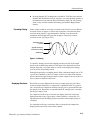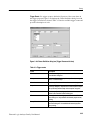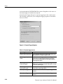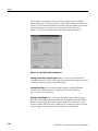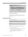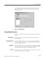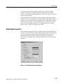
1
User Manual
Tektronix Logic Analyzer Family
Version 4.3 Software
071-1236-00
www.tektronix.com
Copyright © Tektronix, Inc. All rights reserved. Licensed software products are owned by Tektronix or its suppliers and
are protected by United States copyright laws and international treaty provisions.
Use, duplication, or disclosure by the Government is subject to restrictions as set forth in subparagraph (c)(1)(ii) of the
Rights in Technical Data and Computer Software clause at DFARS 252.227-7013, or subparagraphs (c)(1) and (2) of the
Commercial Computer Software - Restricted Rights clause at FAR 52.227-19, as applicable.
Tektronix products are covered by U.S. and foreign patents, issued and pending. Information in this publication supercedes
that in all previously published material. Specifications and price change privileges reserved.
Tektronix, Inc., 14200 SW Karl Braun Drive, Beaverton, OR 97077
TEKTRONIX, TEK, TLAVu, PatGenVu, and MagniVu are registered trademarks of Tektronix, Inc.
HARDWARE WARRANTY
Tektronix warrants that the products that it manufactures and sells will be free from defects in materials and workmanship
for a period of one (1) year from the date of shipment. If a product proves defective during this warranty period, Tektronix,
at its option, either will repair the defective product without charge for parts and labor, or will provide a replacement in
exchange for the defective product.
In order to obtain service under this warranty, Customer must notify Tektronix of the defect before the expiration of the
warranty period and make suitable arrangements for the performance of service. Customer shall be responsible for
packaging and shipping the defective product to the service center designated by Tektronix, with shipping charges prepaid.
Tektronix shall pay for the return of the product to Customer if the shipment is to a location within the country in which the
Tektronix service center is located. Customer shall be responsible for paying all shipping charges, duties, taxes, and any
other charges for products returned to any other locations.
This warranty shall not apply to any defect, failure or damage caused by improper use or improper or inadequate
maintenance and care. Tektronix shall not be obligated to furnish service under this warranty a) to repair damage resulting
from attempts by personnel other than Tektronix representatives to install, repair or service the product; b) to repair
damage resulting from improper use or connection to incompatible equipment; c) to repair any damage or malfunction
caused by the use of non-Tektronix supplies; or d) to service a product that has been modified or integrated with other
products when the effect of such modification or integration increases the time or difficulty of servicing the product.
THIS WARRANTY IS GIVEN BY TEKTRONIX IN LIEU OF ANY OTHER WARRANTIES, EXPRESS OR
IMPLIED. TEKTRONIX AND ITS VENDORS DISCLAIM ANY IMPLIED WARRANTIES OF
MERCHANTABILITY OR FITNESS FOR A PARTICULAR PURPOSE. TEKTRONIX’ RESPONSIBILITY TO
REPAIR OR REPLACE DEFECTIVE PRODUCTS IS THE SOLE AND EXCLUSIVE REMEDY PROVIDED TO
THE CUSTOMER FOR BREACH OF THIS WARRANTY. TEKTRONIX AND ITS VENDORS WILL NOT BE
LIABLE FOR ANY INDIRECT, SPECIAL, INCIDENTAL, OR CONSEQUENTIAL DAMAGES IRRESPECTIVE
OF WHETHER TEKTRONIX OR THE VENDOR HAS ADVANCE NOTICE OF THE POSSIBILITY OF SUCH
DAMAGES.
SOFTWARE WARRANTY
Tektronix warrants that the media on which this software product is furnished and the encoding of the programs on the
media will be free from defects in materials and workmanship for a period of three (3) months from the date of shipment.
If a medium or encoding proves defective during the warranty period, Tektronix will provide a replacement in exchange
for the defective medium. Except as to the media on which this software product is furnished, this software product is
provided “as is” without warranty of any kind, either express or implied. Tektronix does not warrant that the functions
contained in this software product will meet Customer’s requirements or that the operation of the programs will be
uninterrupted or error-free.
In order to obtain service under this warranty, Customer must notify Tektronix of the defect before the expiration of the
warranty period. If Tektronix is unable to provide a replacement that is free from defects in materials and workmanship
within a reasonable time thereafter, Customer may terminate the license for this software product and return this software
product and any associated materials for credit or refund.
THIS WARRANTY IS GIVEN BY TEKTRONIX IN LIEU OF ANY OTHER WARRANTIES, EXPRESS OR
IMPLIED. TEKTRONIX AND ITS VENDORS DISCLAIM ANY IMPLIED WARRANTIES OF
MERCHANTABILITY OR FITNESS FOR A PARTICULAR PURPOSE. TEKTRONIX’ RESPONSIBILITY TO
REPLACE DEFECTIVE MEDIA OR REFUND CUSTOMER’S PAYMENT IS THE SOLE AND EXCLUSIVE
REMEDY PROVIDED TO THE CUSTOMER FOR BREACH OF THIS WARRANTY. TEKTRONIX AND ITS
VENDORS WILL NOT BE LIABLE FOR ANY INDIRECT, SPECIAL, INCIDENTAL, OR CONSEQUENTIAL
DAMAGES IRRESPECTIVE OF WHETHER TEKTRONIX OR THE VENDOR HAS ADVANCE NOTICE OF
THE POSSIBILITY OF SUCH DAMAGES.
Table of Contents
General Safety Summary . . . . . . . . . . . . . . . . . . . . . . . . . . . . . . . . . . .
Preface . . . . . . . . . . . . . . . . . . . . . . . . . . . . . . . . . . . . . . . . . . . . . . . . . . .
ix
xi
Related Documentation . . . . . . . . . . . . . . . . . . . . . . . . . . . . . . . . . . . . . . . . . . .
Contacting Tektronix . . . . . . . . . . . . . . . . . . . . . . . . . . . . . . . . . . . . . . . . . . . . .
xi
xii
Getting Started . . . . . . . . . . . . . . . . . . . . . . . . . . . . . . . . . . . . . . . . . . . .
1--1
Tektronix Logic Analyzer Family . . . . . . . . . . . . . . . . . . . . . . . . . . . . . . . . . . .
Accessories . . . . . . . . . . . . . . . . . . . . . . . . . . . . . . . . . . . . . . . . . . . . . . . . . . . . .
Installation . . . . . . . . . . . . . . . . . . . . . . . . . . . . . . . . . . . . . . . . . . . . . . . . . . . . .
Functional Check . . . . . . . . . . . . . . . . . . . . . . . . . . . . . . . . . . . . . . . . . . . . . . . .
1-- 1
1-- 3
1-- 3
1-- 3
Operating Basics . . . . . . . . . . . . . . . . . . . . . . . . . . . . . . . . . . . . . . . . . .
2--1
Sampling and Digitizing a Signal . . . . . . . . . . . . . . . . . . . . . . . . . . . . . . . . . . .
Logic Analyzer . . . . . . . . . . . . . . . . . . . . . . . . . . . . . . . . . . . . . . . . . . . . . . . . . .
iView External Oscilloscope . . . . . . . . . . . . . . . . . . . . . . . . . . . . . . . . . . . . . . .
Pattern Generator Module . . . . . . . . . . . . . . . . . . . . . . . . . . . . . . . . . . . . . . . . .
Logic Analyzer Conceptual Model . . . . . . . . . . . . . . . . . . . . . . . . . . . . . . . . . .
Intermodule Interactions and Time Correlation . . . . . . . . . . . . . . . . . . . . . . . . .
Listing-Data Concepts . . . . . . . . . . . . . . . . . . . . . . . . . . . . . . . . . . . . . . . . . . . .
Microprocessor Support . . . . . . . . . . . . . . . . . . . . . . . . . . . . . . . . . . . . . . . . . . .
High-Level Language (Source Code) Support . . . . . . . . . . . . . . . . . . . . . . . . . .
Waveform Data Concepts . . . . . . . . . . . . . . . . . . . . . . . . . . . . . . . . . . . . . . . . . .
Performance Analysis Concepts . . . . . . . . . . . . . . . . . . . . . . . . . . . . . . . . . . . . .
Comparing Acquired Data Against Saved Data . . . . . . . . . . . . . . . . . . . . . . . . .
Repetitive Acquisitions . . . . . . . . . . . . . . . . . . . . . . . . . . . . . . . . . . . . . . . . . . .
Data Filters . . . . . . . . . . . . . . . . . . . . . . . . . . . . . . . . . . . . . . . . . . . . . . . . . . . . .
Symbol Support . . . . . . . . . . . . . . . . . . . . . . . . . . . . . . . . . . . . . . . . . . . . . . . . .
2-- 1
2-- 2
2-- 4
2-- 4
2-- 5
2-- 6
2-- 6
2-- 8
2-- 8
2-- 10
2-- 16
2-- 17
2-- 18
2-- 19
2-- 20
Setup . . . . . . . . . . . . . . . . . . . . . . . . . . . . . . . . . . . . . . . . . . . . . . . . . . . .
3--1
The System Window . . . . . . . . . . . . . . . . . . . . . . . . . . . . . . . . . . . . . . . . . . . . . .
Setting Up the LA Module . . . . . . . . . . . . . . . . . . . . . . . . . . . . . . . . . . . . . . . . .
Setting Up the Trigger Program . . . . . . . . . . . . . . . . . . . . . . . . . . . . . . . . . . . . .
Setting Up the Oscilloscope Module . . . . . . . . . . . . . . . . . . . . . . . . . . . . . . . . .
Setting Up the iView External Oscilloscope . . . . . . . . . . . . . . . . . . . . . . . . . . .
System Trigger . . . . . . . . . . . . . . . . . . . . . . . . . . . . . . . . . . . . . . . . . . . . . . . . . .
Arming Modules . . . . . . . . . . . . . . . . . . . . . . . . . . . . . . . . . . . . . . . . . . . . . . . . .
Intermodule and External Signaling . . . . . . . . . . . . . . . . . . . . . . . . . . . . . . . . . .
Merging Modules . . . . . . . . . . . . . . . . . . . . . . . . . . . . . . . . . . . . . . . . . . . . . . . .
Saving and Loading Setups, Triggers, and Data . . . . . . . . . . . . . . . . . . . . . . . .
System Options . . . . . . . . . . . . . . . . . . . . . . . . . . . . . . . . . . . . . . . . . . . . . . . . . .
Menu Shortcut Keys . . . . . . . . . . . . . . . . . . . . . . . . . . . . . . . . . . . . . . . . . . . . . .
3-- 1
3-- 2
3-- 28
3-- 43
3-- 48
3-- 51
3-- 53
3-- 54
3-- 56
3-- 58
3-- 61
3-- 62
Getting Started
Operating Basics
Reference
Tektronix Logic Analzyer Family User Manual
i
Table of Contents
ii
Acquisition . . . . . . . . . . . . . . . . . . . . . . . . . . . . . . . . . . . . . . . . . . . . . . .
3--63
Starting and Stopping Acquisition . . . . . . . . . . . . . . . . . . . . . . . . . . . . . . . . . . .
Viewing Acquisition Activity . . . . . . . . . . . . . . . . . . . . . . . . . . . . . . . . . . . . . .
If the Logic Analyzer Does Not Trigger . . . . . . . . . . . . . . . . . . . . . . . . . . . . . .
3-- 63
3-- 65
3-- 65
Display . . . . . . . . . . . . . . . . . . . . . . . . . . . . . . . . . . . . . . . . . . . . . . . . . .
3--67
Opening an Existing Data Window . . . . . . . . . . . . . . . . . . . . . . . . . . . . . . . . . .
Opening a Saved Data Window . . . . . . . . . . . . . . . . . . . . . . . . . . . . . . . . . . . . .
Aligning Saved Data with Current Data . . . . . . . . . . . . . . . . . . . . . . . . . . . . . .
Locking Windows . . . . . . . . . . . . . . . . . . . . . . . . . . . . . . . . . . . . . . . . . . . . . . . .
Creating a New Data Window . . . . . . . . . . . . . . . . . . . . . . . . . . . . . . . . . . . . . .
General Purpose Data Window Shortcut Keys . . . . . . . . . . . . . . . . . . . . . . . . .
3-- 68
3-- 68
3-- 69
3-- 69
3-- 69
3-- 70
Waveform Window . . . . . . . . . . . . . . . . . . . . . . . . . . . . . . . . . . . . . . . .
3--71
Types of Waveforms . . . . . . . . . . . . . . . . . . . . . . . . . . . . . . . . . . . . . . . . . . . . . .
Reading the Waveform Indicators . . . . . . . . . . . . . . . . . . . . . . . . . . . . . . . . . . .
Automatic Waveform Measurements . . . . . . . . . . . . . . . . . . . . . . . . . . . . . . . . .
Jumping to Specific Data Locations . . . . . . . . . . . . . . . . . . . . . . . . . . . . . . . . .
Searching Data . . . . . . . . . . . . . . . . . . . . . . . . . . . . . . . . . . . . . . . . . . . . . . . . . .
Filtering Data . . . . . . . . . . . . . . . . . . . . . . . . . . . . . . . . . . . . . . . . . . . . . . . . . . .
MagniVu Data . . . . . . . . . . . . . . . . . . . . . . . . . . . . . . . . . . . . . . . . . . . . . . . . . . .
Changing iConnect Data . . . . . . . . . . . . . . . . . . . . . . . . . . . . . . . . . . . . . . . . . .
Comparing Waveform Data . . . . . . . . . . . . . . . . . . . . . . . . . . . . . . . . . . . . . . . .
Adjusting the Waveform Window . . . . . . . . . . . . . . . . . . . . . . . . . . . . . . . . . . .
Customizing the Waveform Window Data . . . . . . . . . . . . . . . . . . . . . . . . . . . .
Exporting Waveform Data . . . . . . . . . . . . . . . . . . . . . . . . . . . . . . . . . . . . . . . . .
Waveform Window Shortcut Keys . . . . . . . . . . . . . . . . . . . . . . . . . . . . . . . . . . .
Overlay Waveforms . . . . . . . . . . . . . . . . . . . . . . . . . . . . . . . . . . . . . . . . . . . . . .
3-- 72
3-- 74
3-- 75
3-- 79
3-- 80
3-- 82
3-- 83
3-- 85
3-- 87
3-- 88
3-- 91
3-- 92
3-- 92
3-- 93
Listing Window . . . . . . . . . . . . . . . . . . . . . . . . . . . . . . . . . . . . . . . . . . .
3--95
Reading the Listing Window Indicators . . . . . . . . . . . . . . . . . . . . . . . . . . . . . . .
Jumping to Specific Data Locations . . . . . . . . . . . . . . . . . . . . . . . . . . . . . . . . .
Searching Data . . . . . . . . . . . . . . . . . . . . . . . . . . . . . . . . . . . . . . . . . . . . . . . . . .
Filtering Data . . . . . . . . . . . . . . . . . . . . . . . . . . . . . . . . . . . . . . . . . . . . . . . . . . .
MagniVu Data . . . . . . . . . . . . . . . . . . . . . . . . . . . . . . . . . . . . . . . . . . . . . . . . . . .
Comparing Listing Data . . . . . . . . . . . . . . . . . . . . . . . . . . . . . . . . . . . . . . . . . . .
Adjusting the Listing Window . . . . . . . . . . . . . . . . . . . . . . . . . . . . . . . . . . . . . .
Customizing the Listing Window Data Area . . . . . . . . . . . . . . . . . . . . . . . . . . .
Exporting Listing Data . . . . . . . . . . . . . . . . . . . . . . . . . . . . . . . . . . . . . . . . . . . .
Listing Window Shortcut Keys . . . . . . . . . . . . . . . . . . . . . . . . . . . . . . . . . . . . .
3-- 95
3-- 97
3-- 98
3-- 99
3-- 99
3-- 100
3-- 102
3-- 104
3-- 105
3-- 108
Source Window . . . . . . . . . . . . . . . . . . . . . . . . . . . . . . . . . . . . . . . . . . .
3--109
Creating a Source Window . . . . . . . . . . . . . . . . . . . . . . . . . . . . . . . . . . . . . . . . .
Reading the Source Window Indicators . . . . . . . . . . . . . . . . . . . . . . . . . . . . . . .
Jumping to Specific Data Locations . . . . . . . . . . . . . . . . . . . . . . . . . . . . . . . . .
Moving Through Source Files . . . . . . . . . . . . . . . . . . . . . . . . . . . . . . . . . . . . . .
Searching for Source Data . . . . . . . . . . . . . . . . . . . . . . . . . . . . . . . . . . . . . . . . .
Adjusting the Source Window . . . . . . . . . . . . . . . . . . . . . . . . . . . . . . . . . . . . . .
Customizing the Source Window Data Area . . . . . . . . . . . . . . . . . . . . . . . . . . .
Locating Source Files . . . . . . . . . . . . . . . . . . . . . . . . . . . . . . . . . . . . . . . . . . . . .
Source Window Shortcut Keys . . . . . . . . . . . . . . . . . . . . . . . . . . . . . . . . . . . . . .
3-- 110
3-- 110
3-- 111
3-- 111
3-- 114
3-- 116
3-- 116
3-- 116
3-- 119
Histogram Window . . . . . . . . . . . . . . . . . . . . . . . . . . . . . . . . . . . . . . . .
3--121
Measuring Histogram Data . . . . . . . . . . . . . . . . . . . . . . . . . . . . . . . . . . . . . . . . .
Creating a Histogram Window . . . . . . . . . . . . . . . . . . . . . . . . . . . . . . . . . . . . . .
Adjusting the Histogram Window . . . . . . . . . . . . . . . . . . . . . . . . . . . . . . . . . . .
3-- 122
3-- 123
3-- 124
Tektronix Logic Analzyer Family User Manual
Table of Contents
Customizing the Histogram Window Data Area . . . . . . . . . . . . . . . . . . . . . . . .
Exporting Histogram Data . . . . . . . . . . . . . . . . . . . . . . . . . . . . . . . . . . . . . . . . .
Histogram Window Shortcut Keys . . . . . . . . . . . . . . . . . . . . . . . . . . . . . . . . . . .
3-- 125
3-- 126
3-- 127
Graph Window . . . . . . . . . . . . . . . . . . . . . . . . . . . . . . . . . . . . . . . . . . .
3--129
Creating a Graph Window . . . . . . . . . . . . . . . . . . . . . . . . . . . . . . . . . . . . . . . . .
Adding a Data Series to the Graph Window . . . . . . . . . . . . . . . . . . . . . . . . . . .
Reading the Graph Window Indicators . . . . . . . . . . . . . . . . . . . . . . . . . . . . . . .
Taking Cursor Measurements . . . . . . . . . . . . . . . . . . . . . . . . . . . . . . . . . . . . . . .
Jumping to Specific Data Locations . . . . . . . . . . . . . . . . . . . . . . . . . . . . . . . . .
Adjusting the Graph Window . . . . . . . . . . . . . . . . . . . . . . . . . . . . . . . . . . . . . . .
Graph Window Properties . . . . . . . . . . . . . . . . . . . . . . . . . . . . . . . . . . . . . . . . .
3-- 129
3-- 130
3-- 130
3-- 131
3-- 131
3-- 131
3-- 133
Protocol Window . . . . . . . . . . . . . . . . . . . . . . . . . . . . . . . . . . . . . . . . . .
3--135
Packet View . . . . . . . . . . . . . . . . . . . . . . . . . . . . . . . . . . . . . . . . . . . . . . . . . . . .
Decode View . . . . . . . . . . . . . . . . . . . . . . . . . . . . . . . . . . . . . . . . . . . . . . . . . . . .
Hex View . . . . . . . . . . . . . . . . . . . . . . . . . . . . . . . . . . . . . . . . . . . . . . . . . . . . . .
Using Marks . . . . . . . . . . . . . . . . . . . . . . . . . . . . . . . . . . . . . . . . . . . . . . . . . . . .
Selecting Stacks . . . . . . . . . . . . . . . . . . . . . . . . . . . . . . . . . . . . . . . . . . . . . . . . .
Filtering Protocol Display . . . . . . . . . . . . . . . . . . . . . . . . . . . . . . . . . . . . . . . . .
Searching the Protocol Display . . . . . . . . . . . . . . . . . . . . . . . . . . . . . . . . . . . . .
Protocol Window Properties . . . . . . . . . . . . . . . . . . . . . . . . . . . . . . . . . . . . . . . .
Generic and Bus-Specific Framers . . . . . . . . . . . . . . . . . . . . . . . . . . . . . . . . . . .
3-- 136
3-- 136
3-- 136
3-- 136
3-- 137
3-- 137
3-- 138
3-- 139
3-- 140
Protocol Designer . . . . . . . . . . . . . . . . . . . . . . . . . . . . . . . . . . . . . . . . . .
3--143
Protocol Editor Pane . . . . . . . . . . . . . . . . . . . . . . . . . . . . . . . . . . . . . . . . . . . . . .
Compilation Result Pane . . . . . . . . . . . . . . . . . . . . . . . . . . . . . . . . . . . . . . . . . .
Stack Definition Pane . . . . . . . . . . . . . . . . . . . . . . . . . . . . . . . . . . . . . . . . . . . . .
Stack Protocol Information Pane . . . . . . . . . . . . . . . . . . . . . . . . . . . . . . . . . . . .
Add Protocol Dialog Box . . . . . . . . . . . . . . . . . . . . . . . . . . . . . . . . . . . . . . . . .
Replace Protocol Dialog Box . . . . . . . . . . . . . . . . . . . . . . . . . . . . . . . . . . . . . . .
Protocol Setup Properties . . . . . . . . . . . . . . . . . . . . . . . . . . . . . . . . . . . . . . . . . .
3-- 144
3-- 144
3-- 145
3-- 145
3-- 146
3-- 146
3-- 146
iVerify . . . . . . . . . . . . . . . . . . . . . . . . . . . . . . . . . . . . . . . . . . . . . . . . . . .
3--149
Creating a New iVerify Setup . . . . . . . . . . . . . . . . . . . . . . . . . . . . . . . . . . . . . . .
Performing iVerify Measurements . . . . . . . . . . . . . . . . . . . . . . . . . . . . . . . . . . .
iVerify Window Properties . . . . . . . . . . . . . . . . . . . . . . . . . . . . . . . . . . . . . . . . .
3-- 149
3-- 151
3-- 151
AutoDeskew . . . . . . . . . . . . . . . . . . . . . . . . . . . . . . . . . . . . . . . . . . . . . .
3--153
Creating a New AutoDeskew Setup . . . . . . . . . . . . . . . . . . . . . . . . . . . . . . . . . .
AutoDeskew Setup Dialog Box . . . . . . . . . . . . . . . . . . . . . . . . . . . . . . . . . . . . .
AutoDeskew Modes . . . . . . . . . . . . . . . . . . . . . . . . . . . . . . . . . . . . . . . . . . . . . .
Loading a AutoDeskew Setup . . . . . . . . . . . . . . . . . . . . . . . . . . . . . . . . . . . . . .
Applying the AutoDeskew Results . . . . . . . . . . . . . . . . . . . . . . . . . . . . . . . . . .
AutoDeskew Properties . . . . . . . . . . . . . . . . . . . . . . . . . . . . . . . . . . . . . . . . . . .
3-- 154
3-- 154
3-- 156
3-- 156
3-- 156
3-- 157
Glossary
Index
Tektronix Logic Analzyer Family User Manual
iii
Table of Contents
List of Figures
iv
Figure 1--1: TLA5000 series logic analyzer . . . . . . . . . . . . . . . . . . . . .
Figure 1--2: Portable mainframe . . . . . . . . . . . . . . . . . . . . . . . . . . . . .
Figure 1--3: Benchtop mainframe with an expansion mainframe . . .
1--1
1--2
1--2
Figure 2--1: Acquiring a digital signal . . . . . . . . . . . . . . . . . . . . . . . . .
Figure 2--2: Acquiring an analog signal (DSO module) . . . . . . . . . . .
Figure 2--3: Block diagram of the logic analyzer acquisition and
storage . . . . . . . . . . . . . . . . . . . . . . . . . . . . . . . . . . . . . . . . . . . . . . .
Figure 2--4: Block diagram of the pattern generator module . . . . . .
Figure 2--5: Logic analyzer conceptual model . . . . . . . . . . . . . . . . . . .
Figure 2--6: Listing data . . . . . . . . . . . . . . . . . . . . . . . . . . . . . . . . . . . .
Figure 2--7: Listing data using a microprocessor support package .
Figure 2--8: High-level source code . . . . . . . . . . . . . . . . . . . . . . . . . . .
Figure 2--9: Source code viewed as acquired data . . . . . . . . . . . . . . .
Figure 2--10: Waveform data . . . . . . . . . . . . . . . . . . . . . . . . . . . . . . . .
Figure 2--11: Using the iView external oscilloscope to capture a
runt pulse . . . . . . . . . . . . . . . . . . . . . . . . . . . . . . . . . . . . . . . . . . . . .
Figure 2--12: Logic analyzer sampling resolution . . . . . . . . . . . . . . . .
Figure 2--13: Aliasing . . . . . . . . . . . . . . . . . . . . . . . . . . . . . . . . . . . . . . .
Figure 2--14: Logic analyzer triggering on a glitch . . . . . . . . . . . . . .
Figure 2--15: Oscilloscope triggering on a glitch . . . . . . . . . . . . . . . . .
Figure 2--16: Viewing the performance of code with a
Histogram window . . . . . . . . . . . . . . . . . . . . . . . . . . . . . . . . . . . . .
Figure 2--17: Using color to show memory differences in a
Listing window . . . . . . . . . . . . . . . . . . . . . . . . . . . . . . . . . . . . . . . .
Figure 2--18: Defining repetitive setups . . . . . . . . . . . . . . . . . . . . . . . .
Figure 2--19: Filter definition . . . . . . . . . . . . . . . . . . . . . . . . . . . . . . . .
Figure 2--20: Using symbols in a trigger program . . . . . . . . . . . . . . .
Figure 2--21: Waveforms using pattern symbols . . . . . . . . . . . . . . . . .
Figure 2--22: Listing data using range symbols . . . . . . . . . . . . . . . . .
Figure 2--23: Symbols dialog box . . . . . . . . . . . . . . . . . . . . . . . . . . . . .
Figure 2--24: Load Symbols Options dialog box . . . . . . . . . . . . . . . . .
2--1
2--2
2--17
2--18
2--19
2--20
2--22
2--23
2--24
2--25
Figure 3--1: System window . . . . . . . . . . . . . . . . . . . . . . . . . . . . . . . . .
Figure 3--2: Logic analyzer setup window . . . . . . . . . . . . . . . . . . . . . .
Figure 3--3: Setup window with the QSTART support package . . . .
3--1
3--2
3--3
2--2
2--4
2--5
2--7
2--8
2--9
2--9
2--10
2--11
2--12
2--13
2--15
2--15
2--16
Tektronix Logic Analzyer Family User Manual
Table of Contents
Figure 3--4: Sample Suppression dialog box . . . . . . . . . . . . . . . . . . . .
Figure 3--5: Selecting channels for memory compare . . . . . . . . . . . .
Figure 3--6: Enabling data compare . . . . . . . . . . . . . . . . . . . . . . . . . . .
Figure 3--7: Typical DDR SDRAM consecutive READ bursts . . . . .
Figure 3--8: Truth Table for the COMMAND group . . . . . . . . . . . . .
Figure 3--9: Typical DDR SDRAM consecutive WRITE to WRITE
Figure 3--10: Edge Detector assignments . . . . . . . . . . . . . . . . . . . . . . .
Figure 3--11: Clock Groups selection . . . . . . . . . . . . . . . . . . . . . . . . . .
Figure 3--12: Sample Clocks equations . . . . . . . . . . . . . . . . . . . . . . . .
Figure 3--13: Group Clocking programming . . . . . . . . . . . . . . . . . . .
Figure 3--14: Probe Demux channel selections . . . . . . . . . . . . . . . . . .
Figure 3--15: Source and destination probe channels in
Internal 2X Clocking mode . . . . . . . . . . . . . . . . . . . . . . . . . . . . . .
Figure 3--16: Channel grouping table in the Setup window . . . . . . .
Figure 3--17: iConnect dialog box . . . . . . . . . . . . . . . . . . . . . . . . . . . . .
Figure 3--18: Route from LA dialog box . . . . . . . . . . . . . . . . . . . . . . .
Figure 3--19: Route to DSO dialog box . . . . . . . . . . . . . . . . . . . . . . . .
Figure 3--20: Activity Indicators dialog box . . . . . . . . . . . . . . . . . . . .
Figure 3--21: Probe Thresholds dialog box . . . . . . . . . . . . . . . . . . . . .
Figure 3--22: Probe Info dialog box . . . . . . . . . . . . . . . . . . . . . . . . . . .
Figure 3--23: Sample EasyTrigger program . . . . . . . . . . . . . . . . . . . .
Figure 3--24: Sample PowerTrigger program . . . . . . . . . . . . . . . . . . .
Figure 3--25: EasyTrigger tab structure . . . . . . . . . . . . . . . . . . . . . . .
Figure 3--26: PowerTrigger tab structure . . . . . . . . . . . . . . . . . . . . . .
Figure 3--27: Overview portion of LA Trigger window . . . . . . . . . . .
Figure 3--28: Trigger detail portion of LA Trigger window . . . . . . .
Figure 3--29: Clause Definition dialog box (Trigger Resources
list box) . . . . . . . . . . . . . . . . . . . . . . . . . . . . . . . . . . . . . . . . . . . . . . .
Figure 3--30: Clause Definition dialog box (Trigger Actions
list box) . . . . . . . . . . . . . . . . . . . . . . . . . . . . . . . . . . . . . . . . . . . . . . .
Figure 3--31: Using trigger storage . . . . . . . . . . . . . . . . . . . . . . . . . . . .
Figure 3--32: DSO Setup window . . . . . . . . . . . . . . . . . . . . . . . . . . . . .
Figure 3--33: DSO Setup window Horizontal settings . . . . . . . . . . . .
Figure 3--34: External Oscilloscope Setup tab . . . . . . . . . . . . . . . . . .
Figure 3--35: External oscilloscope trigger tab . . . . . . . . . . . . . . . . . .
Figure 3--36: External Oscilloscope Connections tab . . . . . . . . . . . . .
Figure 3--37: System Trigger dialog box . . . . . . . . . . . . . . . . . . . . . . .
Figure 3--38: Signals property page . . . . . . . . . . . . . . . . . . . . . . . . . . .
Figure 3--39: Merging modules . . . . . . . . . . . . . . . . . . . . . . . . . . . . . . .
Tektronix Logic Analzyer Family User Manual
3--5
3--6
3--6
3--11
3--12
3--13
3--14
3--14
3--15
3--16
3--16
3--20
3--21
3--21
3--24
3--25
3--26
3--27
3--28
3--30
3--30
3--32
3--33
3--34
3--34
3--35
3--38
3--40
3--43
3--46
3--49
3--50
3--51
3--52
3--54
3--57
v
Table of Contents
Figure 3--40: Logic analyzer conceptual model . . . . . . . . . . . . . . . . . .
Figure 3--41: Loading a saved system that does not match the
current system . . . . . . . . . . . . . . . . . . . . . . . . . . . . . . . . . . . . . . . . .
Figure 3--42: Load System Options dialog box . . . . . . . . . . . . . . . . . .
Figure 3--43: Defining setups for Repetitive mode . . . . . . . . . . . . . . .
Figure 3--44: The Listing and Waveform windows . . . . . . . . . . . . . . .
Figure 3--45: Opening a data window . . . . . . . . . . . . . . . . . . . . . . . . .
Figure 3--46: Waveform window . . . . . . . . . . . . . . . . . . . . . . . . . . . . . .
Figure 3--47: Waveform types . . . . . . . . . . . . . . . . . . . . . . . . . . . . . . . .
Figure 3--48: Magnitude waveform . . . . . . . . . . . . . . . . . . . . . . . . . . .
Figure 3--49: Range readouts . . . . . . . . . . . . . . . . . . . . . . . . . . . . . . . .
Figure 3--50: Waveform window cursors and marks . . . . . . . . . . . . .
Figure 3--51: Measurement Setup dialog box . . . . . . . . . . . . . . . . . . .
Figure 3--52: Sawtooth waveform with automatic measurements . . .
Figure 3--53: Using the Overview Mark bar to jump to a
data location . . . . . . . . . . . . . . . . . . . . . . . . . . . . . . . . . . . . . . . . . . .
Figure 3--54: Defining search criteria . . . . . . . . . . . . . . . . . . . . . . . . .
Figure 3--55: Suppressed samples in a Waveform window . . . . . . . .
Figure 3--56: MagniVu data . . . . . . . . . . . . . . . . . . . . . . . . . . . . . . . . .
Figure 3--57: Route to DSO dialog box . . . . . . . . . . . . . . . . . . . . . . . .
Figure 3--58: Route from LA dialog box . . . . . . . . . . . . . . . . . . . . . . .
Figure 3--59: Selecting compare data colors in the Waveform
Window property page . . . . . . . . . . . . . . . . . . . . . . . . . . . . . . . . . .
Figure 3--60: Add Waveform dialog box . . . . . . . . . . . . . . . . . . . . . . .
Figure 3--61: Waveform with a glitch . . . . . . . . . . . . . . . . . . . . . . . . . .
Figure 3--62: Waveform tab of the Waveform Properties dialog box
Figure 3--63: Example of an overlay waveform . . . . . . . . . . . . . . . . .
Figure 3--64: Waveform properties tab . . . . . . . . . . . . . . . . . . . . . . . .
Figure 3--65: Listing window . . . . . . . . . . . . . . . . . . . . . . . . . . . . . . . .
Figure 3--66: Listing window cursors and marks . . . . . . . . . . . . . . . .
Figure 3--67: Using the Overview Mark bar to jump to a data
location . . . . . . . . . . . . . . . . . . . . . . . . . . . . . . . . . . . . . . . . . . . . . . .
Figure 3--68: Defining search criteria . . . . . . . . . . . . . . . . . . . . . . . . .
Figure 3--69: Selecting compare data colors in the Listing
Window tab . . . . . . . . . . . . . . . . . . . . . . . . . . . . . . . . . . . . . . . . . . .
Figure 3--70: Viewing compare data in a Listing window . . . . . . . . .
Figure 3--71: Add Column dialog box . . . . . . . . . . . . . . . . . . . . . . . . .
Figure 3--72: Export Data dialog box . . . . . . . . . . . . . . . . . . . . . . . . . .
Figure 3--73: Export Data Options dialog box . . . . . . . . . . . . . . . . . .
vi
3--58
3--59
3--60
3--64
3--67
3--68
3--71
3--72
3--73
3--73
3--74
3--75
3--79
3--79
3--81
3--82
3--83
3--86
3--87
3--88
3--90
3--91
3--91
3--93
3--94
3--95
3--96
3--97
3--98
3--101
3--101
3--103
3--105
3--106
Tektronix Logic Analzyer Family User Manual
Table of Contents
Figure 3--74: Source window . . . . . . . . . . . . . . . . . . . . . . . . . . . . . . . . .
Figure 3--75: Accessing the New Data Window wizard . . . . . . . . . . .
Figure 3--76: Source window cursors and marks . . . . . . . . . . . . . . . .
Figure 3--77: Source window controls . . . . . . . . . . . . . . . . . . . . . . . . .
Figure 3--78: Defining source search criteria . . . . . . . . . . . . . . . . . . .
Figure 3--79: Source Files property page . . . . . . . . . . . . . . . . . . . . . . .
Figure 3--80: Modify Search Path list dialog box . . . . . . . . . . . . . . . .
Figure 3--81: Histogram window . . . . . . . . . . . . . . . . . . . . . . . . . . . . .
Figure 3--82: Selecting the data source for the Histogram window .
Figure 3--83: Measuring events with the Histogram window . . . . . .
Figure 3--84: Export Histogram dialog box . . . . . . . . . . . . . . . . . . . . .
Figure 3--85: ASCII histogram data file . . . . . . . . . . . . . . . . . . . . . . . .
Figure 3--86: Graph window . . . . . . . . . . . . . . . . . . . . . . . . . . . . . . . . .
Figure 3--87: Graph window toolbar . . . . . . . . . . . . . . . . . . . . . . . . . .
Figure 3--88: Protocol window . . . . . . . . . . . . . . . . . . . . . . . . . . . . . . .
Figure 3--89: Select Stack dialog box . . . . . . . . . . . . . . . . . . . . . . . . . .
Figure 3--90: Protocol window filter setup . . . . . . . . . . . . . . . . . . . . .
Figure 3--91: Search dialog box . . . . . . . . . . . . . . . . . . . . . . . . . . . . . .
Figure 3--92: Protocol Designer Window . . . . . . . . . . . . . . . . . . . . . . .
Figure 3--93: Protocol Editor and Compilation Result Panes . . . . . .
Figure 3--94: Stack Definition and Stack Protocol Information panes
Figure 3--95: Protocol tab . . . . . . . . . . . . . . . . . . . . . . . . . . . . . . . . . . .
Figure 3--96: Relations tab . . . . . . . . . . . . . . . . . . . . . . . . . . . . . . . . . .
Figure 3--97: iVerify window . . . . . . . . . . . . . . . . . . . . . . . . . . . . . . . . .
Figure 3--98: iVerify Setup dialog box . . . . . . . . . . . . . . . . . . . . . . . . .
Figure 3--99: iVerify Window tab with 4-point mask
measurement settings . . . . . . . . . . . . . . . . . . . . . . . . . . . . . . . . . . .
Figure 3--100: Eye Coloration tab . . . . . . . . . . . . . . . . . . . . . . . . . . . .
Figure 3--101: AutoDeskew window . . . . . . . . . . . . . . . . . . . . . . . . . . .
Figure 3--102: AutoDeskew Setup dialog box . . . . . . . . . . . . . . . . . .
Figure 3--103: AutoDeskew Properties dialog box . . . . . . . . . . . . . . .
Tektronix Logic Analzyer Family User Manual
3--109
3--110
3--110
3--112
3--115
3--117
3--118
3--121
3--122
3--123
3--126
3--127
3--129
3--131
3--135
3--137
3--138
3--139
3--143
3--144
3--145
3--147
3--148
3--149
3--150
3--152
3--152
3--153
3--154
3--157
vii
Table of Contents
List of Tables
viii
Table i: Tektronix Logic Analyzer Family documentation . . . . . . . .
xi
Table 2--1: Using symbols in logic analyzer windows . . . . . . . . . . . .
2--21
Table 3--1: Channel assignments . . . . . . . . . . . . . . . . . . . . . . . . . . . . .
Table 3--2: Group definitions . . . . . . . . . . . . . . . . . . . . . . . . . . . . . . . .
Table 3--3: Trigger events . . . . . . . . . . . . . . . . . . . . . . . . . . . . . . . . . . .
Table 3--4: Trigger resources . . . . . . . . . . . . . . . . . . . . . . . . . . . . . . . .
Table 3--5: Trigger actions . . . . . . . . . . . . . . . . . . . . . . . . . . . . . . . . . .
Table 3--6: Trigger storage . . . . . . . . . . . . . . . . . . . . . . . . . . . . . . . . .
Table 3--7: MagniVu trigger position . . . . . . . . . . . . . . . . . . . . . . . . .
Table 3--8: External oscilloscope setups . . . . . . . . . . . . . . . . . . . . . . .
Table 3--9: External oscilloscope trigger settings . . . . . . . . . . . . . . . .
Table 3--10: System trigger source . . . . . . . . . . . . . . . . . . . . . . . . . . . .
Table 3--11: Menu shortcut keys . . . . . . . . . . . . . . . . . . . . . . . . . . . . .
Table 3--12: General purpose data window shortcut keys . . . . . . . .
Table 3--13: Waveform window cursor and mark summary . . . . . .
Table 3--14: Automatic waveform measurements . . . . . . . . . . . . . . .
Table 3--15: Waveform reference levels . . . . . . . . . . . . . . . . . . . . . . . .
Table 3--16: MagniVu storage rates . . . . . . . . . . . . . . . . . . . . . . . . . . .
Table 3--17: MagniVu trigger positon . . . . . . . . . . . . . . . . . . . . . . . . .
Table 3--18: Waveform window shortcut keys . . . . . . . . . . . . . . . . . .
Table 3--19: Listing window cursor and mark summary . . . . . . . . .
Table 3--20: Listing window shortcut keys . . . . . . . . . . . . . . . . . . . . .
Table 3--21: Source window cursor and mark summary . . . . . . . . .
Table 3--22: Source window shortcut keys . . . . . . . . . . . . . . . . . . . . .
Table 3--23: Histogram window shortcut keys . . . . . . . . . . . . . . . . . .
Table 3--24: Graph window controls and indicators . . . . . . . . . . . . .
3--11
3--12
3--35
3--36
3--38
3--40
3--42
3--49
3--50
3--52
3--62
3--70
3--74
3--76
3--78
3--84
3--85
3--92
3--96
3--108
3--111
3--119
3--127
3--130
Tektronix Logic Analzyer Family User Manual
General Safety Summary
Review the following safety precautions to avoid injury and prevent damage to
this product or any products connected to it. To avoid potential hazards, use this
product only as specified.
Only qualified personnel should perform service procedures.
To Avoid Fire or
Personal Injury
Use Proper Power Cord. Use only the power cord specified for this product and
certified for the country of use.
Connect and Disconnect Properly. Do not connect or disconnect probes or test
leads while they are connected to a voltage source.
Ground the Product. This product is grounded through the grounding conductor
of the power cord. To avoid electric shock, the grounding conductor must be
connected to earth ground. Before making connections to the input or output
terminals of the product, ensure that the product is properly grounded.
Observe All Terminal Ratings. To avoid fire or shock hazard, observe all ratings
and marking on the product. Consult the product manual for further ratings
information before making connections to the product.
The common terminal is at ground potential. Do not connect the common
terminal to elevated voltages.
Do not apply a potential to any terminal, including the common terminal, that
exceeds the maximum rating of that terminal.
Do Not Operate Without Covers. Do not operate this product with covers or panels
removed.
Use Proper Fuse. Use only the fuse type and rating specified for this product.
Avoid Exposed Circuitry. Do not touch exposed connections and components
when power is present.
Do Not Operate With Suspected Failures. If you suspect there is damage to this
product, have it inspected by qualified service personnel.
Do Not Operate in Wet/Damp Conditions.
Do Not Operate in an Explosive Atmosphere.
Keep Product Surfaces Clean and Dry.
Provide Proper Ventilation. Refer to the manual’s installation instructions for
details on installing the product so it has proper ventilation.
Symbols and Terms
Terms in this Manual. These terms may appear in this manual:
Tektronix Logic Analzyer Family User Manual
ix
General Safety Summary
WARNING. Warning statements identify conditions or practices that could result
in injury or loss of life.
CAUTION. Caution statements identify conditions or practices that could result in
damage to this product or other property.
Terms on the Product. These terms may appear on the product:
DANGER indicates an injury hazard immediately accessible as you read the
marking.
WARNING indicates an injury hazard not immediately accessible as you read the
marking.
CAUTION indicates a hazard to property including the product.
Symbols on the Product. The following symbols may appear on the product:
WARNING
High Voltage
Mains Disconnected
OFF (Power)
x
Protective Ground
(Earth) Terminal
CAUTION
Refer to Manual
Double
Insulated
Mains Connected
ON (Power)
Tektronix Logic Analzyer Family User Manual
Preface
This manual provides high-level information for daily use of the Tektronix Logic
Analyzer Family products. Use this manual together with the online help to use
your Tektronix logic analyzer.
Refer to the TLA700 Series Installation Manual or to the TLA5000 Series
Installation Manual to install and configure Tektronix logic analyzer products.
Related Documentation
In addition to this user manual, the documentation listed in Table i is available
for your Tektronix logic analyzer product. For documentation not specified in the
table, contact your local Tektronix representative.
Table i: Tektronix Logic Analyzer Family documentation
Location
TLA Documentation
Documents available in printed form and downloadable from the Tektronix web site.
Tektronix Logic Analyzer Family User Manual
TLA700 Series Installation Manual
TLA5000 Series Installation Manual
P6810, P6860, & P6880 Logic Analyzer Probes Instruction Manual
P6417 & P6418 Logic Analyzer Probes Instructions
P6419 Logic Analyzer Probes Instructions
P6434 Mass Termination Probe Instructions
tektronix.com
TLA7UP Field Upgrade Kit Instructions
TLA6UP Field Upgrade Kit Instructions
Tektronix Logic Analzyer Family User Manual
xi
Preface
Contacting Tektronix
Phone
1-800-833-9200*
Address
Tektronix, Inc.
Department or name (if known)
14200 SW Karl Braun Drive
P.O. Box 500
Beaverton, OR 97077
USA
Web site
www.tektronix.com
Sales support
1-800-833-9200, select option 1*
Service support
1-800-833-9200, select option 2*
Technical support
Email: [email protected]
1-800-833-9200, select option 3*
6:00 a.m. - 5:00 p.m. Pacific time
*
xii
This phone number is toll free in North America. After office hours, please leave a
voice mail message.
Outside North America, contact a Tektronix sales office or distributor; see the
Tektronix web site for a list of offices.
Tektronix Logic Analzyer Family User Manual
Getting Started
Getting Started
The Tektronix Logic Analyzer family consists of the TLA5000, and TLA700
series logic analyzers, and all of the accessories and supporting software that can
be used with them. For more information about availability, contact your
Tektronix representative and view the Tektronix website at: www.tektronix.com.
Tektronix Logic Analyzer Family
The TLA5000 series logic analyzers are a line of self-contained logic analyzers
as shown in Figure 1--1.
Figure 1- 1: TLA5000 series logic analyzer
The TLA700 series logic analyzers combine a high-performance logic analyzer
module with optional application modules or an external Tektronix oscilloscope.
There are two styles of mainframes: portable and benchtop. Each mainframe can
include an expansion mainframe that looks similar to the benchtop mainframe.
The portable mainframe and the benchtop mainframe are shown in Figure 1--2
and Figure 1--3.
Tektronix Logic Analzyer Family User Manual
1- 1
Getting Started
Figure 1- 2: Portable mainframe
Expansion
mainframe
Benchtop
mainframe
Figure 1- 3: Benchtop mainframe with an expansion mainframe
Several logic analyzer modules are available in various combinations of channel
width and memory depth. All of the logic analyzer modules provide simultaneous state and timing measurements through a single probe.
1- 2
Tektronix Logic Analzyer Family User Manual
Getting Started
Accessories
For a complete list of accessories, refer to the online help.
Installation
Refer to the following product-specific installation manuals for complete
instructions for installing your logic analyzer product:
H
TLA5000 Series Logic Analyzer Installation Manual
H
TLA700 Series Logic Analyzer Installation Manual
NOTE. If you have a TLA600 Series Logic Analyzer, refer to the Tektronix Logic
Analyzer Family User Manual for V4.2 software (Tektronix part number
071-0863-02) for installation information.
Functional Check
Use the power-on diagnostics to check the basic functionality of your logic
analyzer product. These diagnostics run every time you turn on the logic
analyzer.
You can verify more detailed functionality by running the self-calibration and
extended diagnostics. Refer to the online help for the self-calibration procedures.
You can also check the functionality of the logic analyzer by connecting a probe
to a single source and verify that the logic analyzer acquires the data. For more
detailed verification procedures, refer to the Performance Verification chapter of
the appropriate service manual for your Tektronix logic analyzer product.
Tektronix Logic Analzyer Family User Manual
1- 3
Getting Started
1- 4
Tektronix Logic Analzyer Family User Manual
Operating Basics
Operating Basics
This section provides an overview of logic analyzer concepts and some of the
features of the Tektronix Logic Analyzer.
To acquire and display signals from the target system, the logic analyzer must
perform a complex series of actions. For the most part, these actions are
transparent.
Sampling and Digitizing a Signal
Acquisition is the process of sampling the input signal, digitizing it to convert it
into digital data, and assembling it into a waveform record. The order and
method of accomplishing these functions is different between logic analyzers and
oscilloscopes.
The logic analyzer converts incoming data into ones and zeros using a comparator with a user-selectable threshold voltage. If the incoming signal is above the
threshold voltage, it is converted to a one; if it is below the threshold voltage, it
is converted to a zero. After digitizing the data, the logic analyzer samples the
data at regular time intervals. The sampled and digitized points are stored in
memory along with corresponding timing information. (See Figure 2--1.)
1 1
1
1 1 1 1 1
Digital values
Threshold voltage
Input signal
0 0
0 0 0
0 0 0
Sample clock
Figure 2- 1: Acquiring a digital signal
Tektronix Logic Analzyer Family User Manual
2- 1
Operating Basics
The oscilloscope samples the voltage level of the signal at regular intervals, and
then converts the sampled analog data into 8-bit digital values (see Figure 2--2).
The sampled and digitized points are stored in memory along with corresponding
timing information.
+6.0 V +5.5 V
+5.0 V
Digital values
Analog signal
2.5 V
0V
+2.0 V
0V
0V
Sample clock
Figure 2- 2: Acquiring an analog signal (DSO module)
Logic Analyzer
Functionally, the logic analyzer can be divided into several blocks, as shown in
Figure 2--3. Refer to the figure as you read about the functional blocks.
Comparator
Data from
target
system
Probes
Sampler
Threshold
voltage
Memory
Trigger
Clock
Internal (asynchronous) or
External (synchronous)
Figure 2- 3: Block diagram of the logic analyzer acquisition and storage
Clocking
Clocks control when data is sampled. The point at which you sample data has a
great deal to do with the type and quality of data you acquire. For the logic
analyzer, there are two primary approaches to clocking, external (synchronous)
clocking and internal (asynchronous) clocking. Generally you use external
clocking for listing data and internal clocking for waveform data.
External (Synchronous) Clocking. This clocking mode is called an external or
synchronous clock because the clock is external to the logic analyzer, and is
synchronized to the target system. External clocking is the best choice when you
are primarily interested in state aspects of the data.
2- 2
Tektronix Logic Analzyer Family User Manual
Operating Basics
The signal you chose as the external clock to the logic analyzer should be the
signal that controls the activity of the other signals you want to observe. For
example, to observe the output states of a counter chip, use the clock input to the
counter chip to act as the external clock source to the logic analyzer. With this
setup, each clock pulse to the counter chip can also be used to clock data from
the counter output lines into the logic analyzer. As another example, to record the
data being written to a latch, you could use the load signal to the latch as the
external clock source to the logic analyzer.
Internal (Asynchronous) Clocking. Much activity can occur in the target system
between system clock signals. Using the logic analyzer’s internal (asynchronous)
clock, you can view all activity in the target system, not just the data available at
the target system clock signal.
Internal clocking is the best choice when you are primarily interested in the
timing aspects of the data. It is important to note, however, that the value of
internal clocking is not limited to displaying waveforms. If you want a detailed
picture of data activity both during and between state changes, use internal
clocking. For example, internal clocking allows you to acquire and display glitch
information in either the Waveform or Listing windows.
Acquiring Data
Triggering and Storage
Qualification
When you start an acquisition, the logic analyzer begins sampling data from the
probes. Then, each time a sample clock occurs, data is sampled. Sampled data is
sent to the trigger functional block and to the main memory.
The trigger program looks at sampled data for specific events and then takes a
specified action. The trigger program can look for events such as data values,
data ranges, or signals from another module. You can also use internal counters
to trigger when the counter reaches a specified value.
When the trigger condition is satisfied, the logic analyzer enables a post trigger
delay counter to allow the post trigger portion of the acquisition memory to fill
before stopping acquisition. You can also indicate a prefill portion of acquisition
memory that must be met before the trigger state machine can store post trigger
data.
The trigger function block includes storage qualification that looks at sampled
data. If the storage conditions are met, a storage qualifier signal enables sampled
data to pass into the acquisition memory as qualified data. Any unqualified data
samples are excluded.
Tektronix Logic Analzyer Family User Manual
2- 3
Operating Basics
Storing Data in Memory
The acquisition memory works like a circular buffer, storing every qualified data
sample until the entire memory is full. After that, each new data sample
overwrites the oldest existing sample. This process continues until the trigger
event is found and the post trigger delay counter reaches the specified value
(based on the trigger position selection), which stops acquisition. During
acquisition, you can monitor the progress of the data storage process using the
Status Monitor.
After storing the data you can display the acquired data in the Listing or
Waveform data windows.
iView External Oscilloscope
The logic analyzer can connect to an external oscilloscope through a special
cable from the logic analyzer to the GPIB port of the oscilloscope. The logic
analyzer transfers setup information and data between the logic analyzer and
oscilloscope.
Use the oscilloscope to acquire the data through the oscilloscope probes and
input circuitry. The logic analyzer can then display the oscilloscope data in one
of the display windows.
Pattern Generator Module
The pattern generator module adds pattern generator capability to the logic
analyzer. You can generate specific data patterns to a target system and then use
the logic analyzer to evaluate the resultant data from the target system.
The pattern generator module functionality can be divided into blocks as shown
in Figure 2--4. Refer to the figure as you read about the functional blocks.
System clock
Event &
Inhibit data
Probes
Program
Probes
Data to target
system
External
clock
Figure 2- 4: Block diagram of the pattern generator module
2- 4
Tektronix Logic Analzyer Family User Manual
Operating Basics
Probes
The probe interface serves two purposes: to detect event and inhibit information
and to output data to a target system. In addition to sending pattern generator
data to the target system, the probe also sends clock and strobe information.
You can connect up to four probes to a single module. Each probe supports either
8 or 16 channels.
Pattern Generator
Program
The pattern generator program is the heart of the pattern generator module. You
can create blocks of data vectors to work together to create complex pattern
generator programs. The program uses external and internal events to determine
specific actions such as loops and branches to other data blocks. The program
can be controlled by an internally selected clock or by an external clock through
a front-panel BNC connector.
Logic Analyzer Conceptual Model
Conceptually, the logic analyzer is made up of two main parts: the modules and
the system. From the operational perspective, a module encompasses the setup,
trigger, and data associated with the physical logic analyzer, the oscilloscope
module installed in the logic analyzer, or the external oscilloscope that is
physically connected to the logic analyzer. See Figure 2--5. The system refers to
the setup and data for the whole logic analyzer.
Some actions occur at the module level, some at the system level. For example,
you can save either module or system files. When you save a module, you save
all the setup and trigger information for that module. (You also have the option
of saving the data for that module.) When you save a system, you save all the
setup information for the system, including data window display settings, and all
the module information, as well.
System
Data Windows
General Settings
Module 1
Module 2
Module n
Setup
Trigger
Data
Setup
Trigger
Data
Setup
Trigger
Data
Figure 2- 5: Logic analyzer conceptual model
Tektronix Logic Analzyer Family User Manual
2- 5
Operating Basics
Intermodule Interactions and Time Correlation
Each module has its own setup, trigger, and clocking functions. (Logic analyzer
modules can include microprocessor support as part of their setup.) Each module
also acquires and stores its own data.
When you start an acquisition, all modules start acquiring data together.
(Exceptions are when one module has been programmed to arm another or when
a module has been turned off.) Modules stop acquiring data individually,
according to their trigger programming. You also have the option of setting the
logic analyzer to operate in repetitive mode, in which the modules acquire data
and update the data windows continually until you manually stop the acquisition.
Modules readily communicate with one another by means of their trigger
programs. You can specify functions such as the following:
H
Trigger all modules (system trigger)
H
One module arms another
H
Modules respond to events declared by another module (internal signals)
After the modules have captured and stored data, you can view the data in a
Listing or Waveform window. All data is time-correlated in the display,
regardless of its source. Due to the precise time stamp information stored with
the data, and the tightly-integrated communications between modules, the logic
analyzer interleaves data acquired from various sources. Because time stamp
information is always stored with the data, you can also compare saved data and
current data with no loss of accuracy.
MagniVu data is also time-correlated with regular data. Because MagniVu data is
always present, you can easily compare a normal acquisition with the MagniVu
counterpart.
Listing-Data Concepts
In many cases, you will use the logic analyzer to observe the data flow in the
target system. The data recorded by the logic analyzer can be displayed in a
listing format, as shown in Figure 2--6.
Listing data is a table of sequential operations performed by the target system. In
the Listing window, each data sample is displayed sequentially. Because each
data sample includes time stamp information, it is a straightforward process to
display acquisitions from multiple data sources. Samples from all specified data
sources are interleaved in chronological order. For clarity, each line in the table
represents a single data sample from a single data source.
2- 6
Tektronix Logic Analzyer Family User Manual
Operating Basics
You control the presentation of the data by selecting the display radix of the
columns. You can also make other format selections such as font size, color, and
column width. You can use filters to display only specific data or to not display
specific data.
Figure 2- 6: Listing data
You can include data acquired by the external oscilloscope in the Listing
window. As with any module, the data samples from the oscilloscope are
time-correlated with the other data and appear on separate lines.
Tektronix Logic Analzyer Family User Manual
2- 7
Operating Basics
Microprocessor Support
For microprocessor applications, the acquired data can be disassembled back into
the assembly language mnemonics used by a particular microprocessor.
Figure 2--7 shows an example of the disassembled mnemonic display format.
Microprocessor support usually requires a special input probe dedicated to a
specific microprocessor.
Figure 2- 7: Listing data using a microprocessor support package
High-Level Language (Source Code) Support
You can correlate the high-level language (HLL) source code that you wrote with
your code as it was executed on your target system and acquired by the logic
analyzer. The correlation is based on symbolic information that is extracted from
your object file or load module. You configure the logic analyzer to access your
source files.
You can step through each executed source statement in the Source window and
view the results in a correlated Listing window. You can also set user-defined
marks as break points within the code and then trace the execution of the code
between the marks. Figure 2--8 on page 2--9 shows an example of viewing
source code in a Source window, while Figure 2--9 shows the actual acquired
data in an associated Listing window.
2- 8
Tektronix Logic Analzyer Family User Manual
Operating Basics
Figure 2- 8: High-level source code
Figure 2- 9: Source code viewed as acquired data
The logic analyzer supports a wide variety of object files including IEEE695,
OMF51, OMF86, OMF286, OMF386, OMF166, COFF, Elf/Dwarf1 and
Dwarf2, Elf/Stabs, and the TLA Symbol File (TSF) format (a text format). Refer
to the online help for information on the TSF format.
Tektronix Logic Analzyer Family User Manual
2- 9
Operating Basics
Waveform Data Concepts
You can use the logic analyzer to observe the timing relationships between
signals by displaying the recorded signal activity as a series of waveforms in the
Waveform window. Figure 2--10 shows waveform data from a logic analyzer.
Figure 2- 10: Waveform data
Each waveform is initially displayed in a separate track, but all waveforms are
time-aligned horizontally and displayed in the same time per division. The
inclusion of time stamp information with the stored data samples makes it easy
to display time-correlated acquisitions from multiple data sources.
You control the horizontal scale of the acquired data in the display. (You do not,
however, change setup parameters by changing settings in the waveform
display.) You can change the channel group radix, waveform color, and
waveform height. Like the Listing window, you can also use filters to display
only specific data or to not display specific data.
When viewing logic analyzer data, you can view the data as individual channels.
You can also display the logic analyzer data in groups of channels known as
busforms. Use the busforms to display when data changes with respect to clock
or control signals. Another method of displaying logic analyzer data is to overlay
waveform channels. Use overlay waveforms to visually compare two or more
waveforms at the same time.
When you are interested in displaying the value of a group of channels over a
period of time, you can use magnitude mode. For example, using magnitude
mode, you can view the channels connected to a 16-bit digital counter. The
magnitude waveform appears as a sawtooth waveform as the counter values
increment from the minimum value (00) to the maximum value (FF).
2- 10
Tektronix Logic Analzyer Family User Manual
Operating Basics
Logic Analyzer
Waveforms Versus
Oscilloscope Waveforms
A logic analyzer waveform appears to have zero-length rise and fall times. This
is because the logic analyzer is recreating the waveform from the samples stored
in its memory, which are either ones or zeros.
No electronic signal is perfectly digital in nature; there is always some analog
component. Consider a fast-rising pulse with ringing on the front edge, or
glitches that can occur in a noisy circuit. If you suspect problems caused by
analog signal characteristics (such as signal voltages higher or lower than
specified voltage levels, or slow transition times), use the iView external
oscilloscope to observe the voltage characteristics of the signal. Figure 2--11
shows where the oscilloscope captured a runt pulse that was below the logic
analyzer’s threshold.
Figure 2- 11: Using the iView external oscilloscope to capture a runt pulse
Sampling Resolution
The accuracy of the waveform depends on the sample clock rate used to record
the incoming signals. This is due to the fact that the waveform recreated by the
logic analyzer is based on the sampled signals stored in its memory. If the
sample clock rate is too slow, the recorded data will produce an inaccurate
display. Figure 2--12 shows how the sample clock rate can affect a logic analyzer
waveform.
Tektronix Logic Analzyer Family User Manual
2- 11
Operating Basics
Example 1: Slow sample clock
Original waveform
Sample clock
Displayed waveform
Example 2: Fast sample clock
Original waveform
Sample clock
Displayed waveform
Figure 2- 12: Logic analyzer sampling resolution
Signal Resolution and
Signal Duration
There is an important trade-off between the resolution of the recorded signal and
its duration in terms of elapsed time. Because the total number of samples that
can be recorded by the logic analyzer is fixed by the depth of the logic analyzer’s
acquisition memory, increasing the sample clock rate provides better signal
resolution at the expense of reducing the duration of the captured signal. That is,
a faster sample clock rate will record a smaller portion of the signal, but with
better resolution; or, you can trade channels or depth to maintain higher
resolution.
It is important to remember that you have two additional tools for the TLA7Lx/
Mx/Nx/Px/Qx logic analyzer modules and TLA600 series logic analyzers. If you
have a TLA7Axx logic analyzer modules or a TLA5000 series logic analyzer,
you have three additional tools to offset the signal resolution/signal duration
relationship:
2- 12
H
By using the MagniVu data feature, you can view high-resolution data
centered about the logic analyzer trigger. This allows you to zoom in on the
data of particular interest while still maintaining visibility of a more
extended signal duration.
H
By using Internal 2X Clocking mode, you can trade one half the channels for
twice the resolution and twice the memory depth. The 2X Clocking mode is
only available with the main timing (not with the MagniVu data feature).
Tektronix Logic Analzyer Family User Manual
Operating Basics
H
Preventing Aliasing
By using Internal 4X Clocking mode available for TLA7Axx logic analyzer
modules and TLA5000 series logic analyzers, you can trade three-quarters of
the channels for four times the speed and memory depth. The 4X Clocking
mode is only available with the main timing (not with the MagniVu data
feature).
Under certain conditions, an analog waveform can be aliased on screen. When a
waveform aliases, it appears on screen with a frequency lower than the actual
waveform being input or it appears unstable. Aliasing occurs because the
instrument cannot sample the signal fast enough to construct an accurate
waveform record. (See Figure 2--13.)
Actual high-frequency
waveform
Apparent low-frequency
waveform due to aliasing
Sampled points
Figure 2- 13: Aliasing
To check for aliasing, increase the sampling rate (decrease the clock sample
period) in the module Setup window. If the shape of the displayed waveform
changes drastically or becomes stable at a faster clock sample period setting,
your waveform was probably aliased.
Although the principles of sampling theory define a minimum sample rate of 2X,
a good rule of thumb is to choose a sample clock rate five times faster than the
speed of the fastest signal being measured. A faster sample clock rate results in a
more accurate reconstructed waveform.
Displaying Waveforms
Waveforms are rarely displayed at an exact one sample point per pixel. Waveforms are usually displayed in a compressed or expanded format. As a general
rule, waveforms are compressed when the time per pixel is greater than the time
per sample clock. Waveforms are expanded when the time per pixel is less than
the time per sample clock.
For compressed oscilloscope waveforms, the display shows the lowest and
highest point that occupy a given pixel column joined by a vertical line. For
expanded waveforms, the display points between the actual sample points are
calculated.
For expanded oscilloscope waveforms, Sin(x)/x interpolation computes the
display points between the actual values acquired.
Tektronix Logic Analzyer Family User Manual
2- 13
Operating Basics
High-Speed Timing
The logic analyzer provides high-speed timing support through MagniVu data.
The MagniVu data is stored in a separate memory that is parallel to the main
memory. All data from the sampler goes directly to the MagniVu memory. The
MagniVu memory also works like a circular buffer. Unlike the acquisition
memory, the MagniVu memory does not qualify data storage through the trigger
function block.
MagniVu data is continuously acquired on all channels at the fastest sample rate
of 500 ps for TLA7Lx/Mx/Nx/Px/Qx logic analyzer modules and TLA600 series
logic analyzers, and 125 ps for TLA7Axx logic analyzer modules and TLA5000
series logic analyzers. Like normal acquisition data, MagniVu data can be
displayed in the Listing or Waveform data windows. For TLA7Lx/Mx/Nx/Px/Qx
logic analyzer modules and TLA600 series logic analyzers, the MagniVu data is
centered on the logic analyzer trigger in the data window. For TLA7Axx logic
analyzer modules and TLA5000 series logic analyzers, the trigger position for
MagniVu data is variable; you control the MagniVu trigger position by a set of
controls in the advanced toolbar. See MagniVu Data on page 3--83 for additional
information.
Detecting Violations
One of the logic analyzer’s most useful features is its ability to detect and trigger
on both signal glitches and setup and hold violations.
A glitch is a signal that makes a transition through the threshold voltage two or
more times between successive acquisition samples. Because glitches are often
signal transitions that occur intermittently, they can cause circuit malfunctions
that are extremely difficult to diagnose.
Although you could try using a very fast sample clock rate to ensure that you
never miss any glitches, a better solution is to use the glitch-detection feature.
The logic analyzer can trigger on a glitch, either alone or in combination with
other signal events. This capability is useful for catching intermittent glitches
that might not occur very often or appear only when a particular operation is
taking place.
You can capture noise spikes and pulse ringing using the glitch capture feature.
Figures 2--14 and 2--15 show data captured by triggering on a glitch. In the
Waveform window, a glitch captured by the logic analyzer is indicated by a band
of color. (See Figure 2--14. For clarity, an arrow identifies the glitch in the
figure.)
A setup and hold violation is a data signal that transitions within the setup and
hold time period. You can identify setup and hold violations by looking at each
clock edge and reviewing all relevant data signals. However, it is more efficient
and reliable to use Setup/Hold triggering to identify violations.
2- 14
Tektronix Logic Analzyer Family User Manual
Operating Basics
You must select the correct clocking mode to use either the glitch detection or
the setup and hold violation features. Choose internal clocking to use glitch
detection; choose external clocking, source synchronous clocking, or custom
clocking to use setup and hold detection. For information on glitch storage, see
Selecting the Acquisition Mode on page 3--17.
Figure 2- 14: Logic analyzer triggering on a glitch
Figure 2- 15: Oscilloscope triggering on a glitch
Tektronix Logic Analzyer Family User Manual
2- 15
Operating Basics
Performance Analysis Concepts
For performance analysis applications, you can use the Histogram window to
view the performance of your software. The actual data is displayed as horizontal
bars in a histogram.
You may want to use the Histogram window to see which one of your software
routines is taking up most of the CPU time. Or, you can use the Histogram
window to measure the amount of time used by a particular subroutine. You can
use a symbol file to view each of the routines by name.
Figure 2--16 shows an example of the Histogram window where the StopLite
routine is taking up most of the computer resources.
Figure 2- 16: Viewing the performance of code with a Histogram window
2- 16
Tektronix Logic Analzyer Family User Manual
Operating Basics
Comparing Acquired Data Against Saved Data
You can use the logic analyzer to compare acquired data against saved reference
data. Use the Setup menu to define the data channels that you want to use during
the compare operations. You can further define the number of samples that you
want to compare as well as data alignment offset.
In the Listing and Waveform windows, you can use color to quickly identify the
compared data. You can set up one color to show where the acquired data does
not equal the reference data. You can use another color to show where the
acquired data equals the reference data.
Figure 2--17 shows a Listing window during a memory compare operation.
Notice that some of the data under the LA 2 A2 column appears in a different
color, indicating that there were differences between the acquired data and the
reference data.
Figure 2- 17: Using color to show memory differences in a Listing window
Tektronix Logic Analzyer Family User Manual
2- 17
Operating Basics
Repetitive Acquisitions
Use the Repetitive acquisition features of the logic analyzer to automate
repetitive and time-consuming tasks. For example, you can specify the number
of times that you want the logic analyzer to acquire data. With each acquisition,
you can save the data to a file for analysis. You can also set up the logic analyzer
to open a file or execute a program when all of the acquisitions have been
completed.
You can set up the logic analyzer to acquire and compare the acquisition data to
known reference data. The logic analyzer can continue acquiring data until there
is a mismatch between the acquisition data and the reference data.
Figure 2--18 shows an example of such a setup where the acquired data is
exported to a file for each acquisition. When a data-mismatch occurs, the logic
analyzer stops acquiring data and exports the data to a file. The faulty data can
now be analyzed by another application.
Figure 2- 18: Defining repetitive setups
2- 18
Tektronix Logic Analzyer Family User Manual
Operating Basics
Data Filters
The logic analyzer normally displays all data acquired by the probes from the
target system. Often times, it displays data that you are not interested in. You can
use data filters to display only the data that you want to see in the data window.
You can define one or more data filters to do the following:
H
Hide specific data. For example, you can define a filter to not display data
when all of the data in a channel group is equal to FFFF.
H
Show specific data. For example, you can define another filter to show data
from a specific address.
H
Color specific data. For example, you can define a filter to display data to
another address with a specified color.
Filters are saved as part of the module setups. You can load filters when you
need them. You can also edit and rename filters.
Filters can be very complex or very simple. The filter definitions are very similar
to trigger definitions. Figure 2--19 shows an example of a filter definition.
Figure 2- 19: Filter definition
Tektronix Logic Analzyer Family User Manual
2- 19
Operating Basics
Symbol Support
Symbols simplify tasks, such as setting up triggers or identifying specific values
within the data. When you program a trigger or view data, it is cumbersome to
remember which numeric channel group values correspond to particular machine
instructions or code modules. The logic analyzer makes this task more manageable by allowing you to assign symbolic names or mnemonics to group values.
For example, assign the symbol WRITE to the control bus event that causes the
target system to write to a memory location. Then, if you want to trigger when a
write cycle occurs, enter WRITE in the trigger program in place of the actual
data value. You can also choose to have WRITE appear in the Listing window
for quick identification of the instruction.
In Figure 2--20, the example shows a trigger program that uses the symbol
BUS_ERROR as part of the trigger clause.
Figure 2- 20: Using symbols in a trigger program
You can use symbol files with a Source window and an associated Listing
window to track the execution of source code. The symbol file provides the
information to associate a line of source code to an address in a Listing window.
When you move a cursor in one window, the symbol file provides the necessary
information to move the cursor to the correct location in the other window.
Often, the application software will define symbols for you. For example, when
you load a microprocessor support package, symbols are also loaded (typically,
to the control group). These symbols represent data values that correspond to bus
cycle types. Other software applications produce range symbol files which you
can load (typically, these files are loaded to the address group).
2- 20
Tektronix Logic Analzyer Family User Manual
Operating Basics
Symbol Files
To use symbols, you must first load or create one or more symbol files that
define the symbols. Symbol files contain symbol names and their associated data
values. You can use symbol files created by another application, edit symbol files
from other applications, or you can create your own symbol files using a text
editor.
Each entry in a symbol file consists of an alphanumeric symbol name with its
associated numeric value or range of values. After you create a symbol file, you
can specify the symbol file for the appropriate channel group in the Waveform or
Listing window, use symbolic names as a substitute for numeric values in the
Trigger and data windows, and use symbols for tracing source code in a Source
window.
Symbol files perform like look-up tables. For example, if the address of a printer
I/O port is at address F734BC, you can define a symbol, printer-port, that
corresponds to that value. Then, in the Trigger window, you can specify the
symbol name as an event in the trigger program and cause the module to trigger
when printer-port (F734BC) appears on the address bus. You can also specify the
symbolic display radix for the address channel group and the symbol name
printer-port will show in the Listing window every time F734BC appears on the
address bus.
Symbol Types. Two main types of symbol files are possible: pattern symbol files
and range symbol files. Range symbols can be further divided into three different
categories: functions, variables, and source code (source). Table 2--1 shows the
different types of symbols and the windows where they are commonly used.
Table 2- 1: Using symbols in logic analyzer windows
Range symbols
Window
Pattern symbols
Functions
Variables
Source code
Listing
Yes
Yes
Yes
Yes
Waveform
Yes
Yes
Yes
Yes
Histogram
No
Yes
Yes
No
Source
No
No
No
Yes
Logic Analyzer Trigger
Yes
Yes
Yes
Yes
Tektronix Logic Analzyer Family User Manual
2- 21
Operating Basics
Pattern Symbols. Pattern symbols consist of data patterns up to 32 bits. Each bit
in a pattern symbol can be 0, 1, or X (don’t care). Pattern symbols are used when
a group of signals define a logical state. For example, a microprocessor has a set
of pins that indicates the type of bus cycle in progress. A memory read cycle is
indicated when the RD~ and MREQ~ pins are 0 (logic low) and the BUSAK~
and M1~ pins are 1 (logic high). You can define a pattern symbol name called
mem-read that corresponds to bit pattern 1100 and thereby mark all memory read
bus cycles in the Listing window. For other bus cycles the logic state of these
pins is also important and you can define different bit patterns for each cycle
type.
Figure 2--21 shows pattern symbols used in a Waveform window.
Figure 2- 21: Waveforms using pattern symbols
Range Symbols. Range symbols define a range of 32-bit addresses represented by
a contiguous set of integers, marked by specific lower and upper bounds. The
different types of range symbols are discussed in detail in Appendix B TLA Symbol File Format.
When defining a range symbol file, do not overlap ranges of values. If ranges
overlap, they may not be recognized. For example, if SYM1 covers the range
1000--3FFF, and SYM2 covers 2000--2FFF, then the values in range 2000--2FFF
may be recognized as either SYM1 or SYM2, and the values in the range
3000--3FFF may not be recognized as SYM1 at all.
The range symbols shown in Figure 2--22 define subroutine boundaries.
2- 22
Tektronix Logic Analzyer Family User Manual
Operating Basics
Figure 2- 22: Listing data using range symbols
Symbols Dialog Box
Use the Symbols dialog box to provide an overview of all currently loaded
symbol files (see Figure 2--23). You can display information about all symbol
files currently used by the logic analyzer.
The following status information is available for each currently loaded symbol
file:
H
The last time the file was loaded into the logic analyzer application software.
It also includes error and warning messages associated with the last load.
H
When the file was last modified. The logic analyzer also displays a message
if the file may need to be reloaded (such as when the file is modified after it
was first loaded).
H
The format of the loaded file.
H
If the file can be unloaded or if the file is currently in use. Symbol files can
only be unloaded if no data windows or setups are using them.
Tektronix Logic Analzyer Family User Manual
2- 23
Operating Basics
Figure 2- 23: Symbols dialog box
The following information is displayed in the Symbols dialog box:
H
Whether the file is a pattern symbol file or a range symbol file. If the file is a
range file, this field also lists the types of symbols loaded.
H
The number of symbols loaded from the file. Symbol files can have an
unlimited number of symbols. The number of symbols is limited by the
amount of memory. When you load a symbol file, the symbols are placed in
memory. Because symbol files consume memory, you should unload unused
symbol files to keep memory available for your main application.
H
The number of source files referenced by source code symbols loaded from
the file.
H
The minimum and maximum address values and offset information.
Click the Load button (see Figure 2--23) to open the Select Symbol File dialog
box and load a new symbol file. You can browse the file system for the symbol
file. If the symbol file is a range file, you can click the Options button in the
Select Symbol File dialog box to open the Load Symbols Options dialog box.
Click the Export button to save the current file as a TSF-format symbol file. You
can view the exported symbol file with applications such as Wordpad. Edit the
symbol file by saving it under a new name and using a text editor. Save the
edited file in text format. You can then load the edited symbol file.
2- 24
Tektronix Logic Analzyer Family User Manual
Operating Basics
Load Symbols Options
Dialog Box
Use the Load Symbols Options dialog box (see Figure 2--24) to specify options
for range symbol files before loading them into the system.
Figure 2- 24: Load Symbols Options dialog box
Select one or more of the symbols types to load. If you want to use the symbol
file with the Source window, you should click the Source Code check box.
You can enter a decimal number for the maximum number of symbols to load.
The maximum number of symbols that you can load is limited only by the
amount of memory available. The file loads symbols until the specified
maximum number of symbols is reached. Additional symbols are ignored, even
if they fall within the Bound 1 and Bound 2 range limits.
The Bound 1 and Bound 2 fields define the range of symbol addresses that will
be loaded. You can enter any hexadecimal values from 0 through FFFFFFFF.
Symbols with values outside of these limits are ignored and will not be loaded.
NOTE. If the lower bound of the range symbol is within the Bound 1 and Bound 2
limits and the higher bound is not, the entire symbol will be valid. However, if
the higher bound is within the Bound 1 and Bound 2 limits and the lower bound
is not, the entire symbol will be ignored.
Tektronix Logic Analzyer Family User Manual
2- 25
Operating Basics
Select either Default Offset or Custom Offset to apply an offset to the symbol
values. If you select Default Offset, the default offset is read from the source file
and applied to each symbol in the file as it is loaded. If you select Custom
Offset, you can add or subtract the specified offset value to each symbol in the
file as it is loaded. You can choose any 32-bit hexadecimal value from 0 to
FFFFFFFF.
When you enter bound values, enter the values without an offset value. If your
application adds an offset, you must subtract the offset value before you enter the
bound values.
2- 26
Tektronix Logic Analzyer Family User Manual
Reference
Setup
The System Window
The System window gives an overview of the logic analyzer configuration,
arming, and triggering relationships. The System window also indicates whether
logic analyzer modules are merged and whether an external oscilloscope has
been set up. See Figure 3--1.
A black arrow from one module to another indicates that one module is set up to
arm another. Figure 3--1 shows the merged logic analyzer module arming the
oscilloscope module.
A module that is programmed to cause a system trigger has an indicator symbol
on the right edge of the module graphic.
Overlapped icons indicating
merged modules
Arm indicator
System trigger indicator
Data source indicator
Figure 3- 1: System window
You can use the System window as a quick navigation tool.
H
To open a module Setup, Trigger, or Program window from the System
window, click the Setup or Trigger button in the module icon.
H
To open a data window from the System window, click the data window
icon.
Tektronix Logic Analzyer Family User Manual
3- 1
Setup
If you are not using a module, you can disable it by clicking the module On/Off
button. When you disable a module, make sure that no other trigger programs
depend on that module output.
You can rename the windows by selecting the current window labels and
overtyping. Names must be unique and are limited to the space available.
If you are unsure which physical module is represented by an icon, double-click
the icon to open its System Properties tab. This property tab lists information
about the module, including the mainframe slot numbers in which it is installed.
(Slot numbers are indicated on the mainframe.)
Setting Up the LA Module
The primary function of the Setup window (see Figure 3--2) is to configure the
logic analyzer for compatibility with the target system. This is where you specify
channel groups, set thresholds, and select the sample clock rate. Additional
selections configure the logic analyzer for best compatibility with the type of
data you want to acquire.
Before you acquire and display data, you must first set up the logic analyzer
using the Setup and Trigger windows. Together, these windows determine the
data to be acquired.
Each module has its own Setup window and Trigger window, and each is set up
individually. You should configure the Setup window before the Trigger window,
because some of the Setup window settings affect Trigger window selections.
Figure 3- 2: Logic analyzer setup window
3- 2
Tektronix Logic Analzyer Family User Manual
Setup
NOTE. If you intend to use merged modules, ensure that the modules are located
in adjacent slots and are physically connected together. If necessary, refer to
Merging Modules in the TLA700 Series Installation Manual for instructions on
physically merging the modules together.
You may also want to refer Merging Modules beginning on page 3--56 for other
information on merging modules before you proceed with the setup procedure.
Microprocessor Support
Setup
If you intend to use a microprocessor support package, load it before completing
the entries in the Setup window. The microprocessor support package configures
the Setup window for you.
To load a microprocessor support package, from the File menu, click Load
Support Package, select the support package you want to load, and then click
Load.
After loading the microprocessor support package, the Setup window shows the
channel definitions, channel groups, and clocking requirements for the microprocessor support package. Figure 3--3 shows an example of the Setup window after
loading the QSTART support package.
Figure 3- 3: Setup window with the QSTART support package
For information about microprocessor support packages, refer to the online help
and to the instruction manual that came with your microprocessor support
package.
Tektronix Logic Analzyer Family User Manual
3- 3
Setup
Performance Analysis
Setups
Data Filters
If you intend to do performance analysis with your logic analyzer, you may want
to load a microprocessor support package that contains the predefined channel
setups and clocking setups. You can also define the channel and clocking setups
in the Setup window if you are not using a microprocessor support package.
You can use data filters to help you focus on the data that you want to see in the
display windows. You can design filters to hide specific data, display specific
data, or to color data. You can design filters for specific modules and then reuse
them with other modules.
Click the Filters button in the Setup window to display the Filters dialog box.
The dialog box lets you manage filters for the entire logic analyzer. You can see
how filters relate to a particular module or data source. You can easily load an
existing filter from a saved setup, edit existing filters, or create new filters
depending on your needs.
Click the Properties button to open a selected filter and to view or edit the filter
definitions. For each filter you can hide data, display data, or color data as it
appears the Listing or Waveform data windows. Within each filter you can add
clauses and event definitions similar to how you use the logic analyzer trigger
windows.
You can easily display the filtered data by creating a new data window with a
defined filter. For example, to display filtered data in a listing window using a
filter named, FilterA:
1. Click the New Data Window button in the toolbar.
2. Select Listing and click the Next button.
3. Select LA1: FilterA (assuming you want to use LA1) and click the Next
button.
4. Assign a name to the new window, or use the default name, and click the
Finish button.
A new data window displays with the filtered data. Refer to the online help for
examples on creating and using filters with the logic analyzer.
Sample Suppression
You can use sample suppression to suppress or hide samples in the display
windows. This can help you focus on the data that you want to see. When you
suppress data samples, the suppressed samples are still in the acquisition
memory; you can turn the sample suppression off to view all the data.
Click the Suppress button at the top of the Setup window to display the Sample
Suppression dialog box (see Figure 3--4). Select one of the options to define the
data suppression. You can select a similar dialog box by right-clicking in one of
the display windows.
3- 4
Tektronix Logic Analzyer Family User Manual
Setup
For more information on data suppression, refer to the online help.
Figure 3- 4: Sample Suppression dialog box
Data Compare
Data Compare allows you to compare the current acquisition data to known
reference data. You can quickly view data differences and similarities in a Listing
or Waveform window using user-defined colors.
Selecting Channels for the Memory Compare. Choose the channels that you want
to compare in the Setup window by selecting Channel Compare in the Table
Shows box (see Figure 3--5). You can then compare all data channels, specific
channel groups, or individual channels by selecting the appropriate channels in
the Probe Channels/Names table.
After selecting the channels that you want to compare, click the Compare button
at the top right side of the Setup window to define the compare actions.
Tektronix Logic Analzyer Family User Manual
3- 5
Setup
Figure 3- 5: Selecting channels for memory compare
Defining Memory Compare Parameters. To enable the Define Compare dialog box
controls, select the Enable Data Compare check box as shown in Figure 3--6.
Select the reference data source in the list box; if the data source that you are
interested in does not appear in the list, click Add Data Source to browse for the
data source in the file system.
Figure 3- 6: Enabling data compare
3- 6
Tektronix Logic Analzyer Family User Manual
Setup
After you select the data source, define the amount of data that you want to
compare against. You can compare all data or a portion of the data by filling in
the appropriate information. You can also define the alignment of the data by
filling in the appropriate information. A summary of your setup displays at the
bottom of the dialog.
NOTE. After defining the compare setup, remember to select Show Compare in
the Listing Window or Waveform Window property page.
Guidelines for Memory Compare. There are a few guidelines that you should be
aware of when using memory compare:
H
You must select the Enable Data Compare check box in the Compare
Definition dialog box (see Figure 3--6).
H
Acquisition modules and reference modules must be the same width.
H
Specify the color of compare data in the Listing Window or Waveform
Window property sheet, or use the default colors.
H
You can search for data differences or data equalities.
H
You can use memory compare with repetitive acquisitions.
H
You can compare only the main logic analyzer data; you cannot compare
glitch data, disassembler group data, or MagniVu data.
NOTE. Although you cannot compare disassembler group data directly, you can
compare the raw data (before it is disassembled) by using the channel groups as
defined in the Setup window. To view these channel groups in a Listing window,
use the Add Column toolbar button to add the channel group to the window.
Clocking
Use Clocking to specify the clock(s) used to sample data. You have several
clocking choices, depending on the instrument you are using; Internal, Internal
2X, and External are available for all instrument types. If you have a TLA7Axx
logic analyzer module or a TLA5000 series logic analyzer, you can also choose
Internal 4X, External 2X, External 2X Double Data Rate (DDR), External 4X,
and Source Sync clocking. Custom clocking is also available, regardless of your
instrument type, if a microprocessor support package has been loaded. Your
clocking choice determines further clocking selections.
Tektronix Logic Analzyer Family User Manual
3- 7
Setup
Internal Clocking. Internal (asynchronous) clocking uses the logic analyzer
internal clock to determine when to sample data. Typically, internal clocking is
used for timing analysis (waveform data).
When you choose Internal clocking, the only additional selection is the clock rate
in the next field.
Because the internal clock signal is asynchronous to the target system, select a
sample period that is considerably faster than the data rate of your target system.
For more information on Internal clocking, refer to the online help.
Internal 2X Clocking. When you use Internal 2X clocking mode, you trade half the
input channels for twice the sampling speed and acquisition depth. You can use
Internal 2X clocking mode with triggering and in both Listing and Waveform
windows.
If you are using a TLA7Lx/Mx/Nx/Px/Qx logic analyzer module or a TLA600
series logic analyzer, Internal 2X clocking provides a sample rate of 2 ns; using a
TLA7Axx logic analyzer module or a TLA5000 series logic analyzer, Internal
2X clocking provides a sample rate of 1 ns.
Internal 4X Clocking. Available for TLA7Axx logic analyzer modules and
TLA5000 series logic analyzers, Internal 4X clocking mode allows you to trade
three quarters of the input channels for four times the sampling speed and four
times the acquisition depth. Internal 4X clocking provides a sample rate of 500
ps.
External Clocking. External (synchronous) clocking synchronizes data sampling
with the clock of the target system so you can be more selective about the data
you sample. This type of clocking is best for state analysis (listing data).
3- 8
Tektronix Logic Analzyer Family User Manual
Setup
When you select External clocking, you have the option of further selections to
define the sample clock. To do so, you create clocking definitions in the
Clocking dialog box. Clocking definitions qualify when data is sampled. The
definitions consist of a Boolean combination of events, linking clock and
qualifier lines. Data is sampled and stored in memory only when the clock
definition is true.
For more information on External clocking, refer to the online help.
Advanced Clocking. Advanced clocking is available only if you select External
clocking. Use advanced clocking to set up multiple-phase clocking, probe
demultiplexing, and other clocking features. Multiple-phase clocking specifies
two different sample clock equations and assigns an equation to separate probe
groups in order to clock in sample data. You can also sample data from different
channel groups at different points in time, relative to the sample clock through a
variable setup and hold window.
For more information on advanced clocking, refer to the online help.
External 2X Clocking. Available in TLA7Axx logic analyzer modules and
TLA5000 series logic analyzers, External 2X clocking allows you to acquire
listing data at twice the normal maximum sample frequency of the logic
analyzer. However, this increased speed and acquisition depth come at the
expense of half the acquisition input channels.
You can access advanced 2X clocking functionality by clicking the More button.
The 2X Clocking dialog box allows you to select the active clock edge and to
align data, in relation to the specified clock edge, for each channel group. The
Setup/Hold window graphic illustrates your clock edge and data alignment
settings.
External 2X DDR Clocking. Available only on TLA7Axx modules, External 2X
Double Data Rate (DDR) clocking allows you to acquire data on both the rising
and falling clock edges at clock rates up to the normal maximum sample
frequency of the logic analyzer. In this mode, half the logic analyzer input
channels are traded for twice the data rate and twice the acquisition depth. When
you use External 2X DDR clocking, you acquire data using a clock rate of up to
450 MHz from the target system. The maximum data rate in External 2X DDR
clocking mode is 900 MB/s.
Tektronix Logic Analzyer Family User Manual
3- 9
Setup
You can access External 2X DDR advanced clocking functionality by selecting a
clocking type of External 2X and then clicking the More button. Note that you
must specify a clock edge of Both. The 2X Clocking dialog box also allows you
to align the data, in relation to the specified clock edge, for each channel group.
The Setup/Hold window graphic illustrates your clock edge(s) and data
alignment settings.
External 4X Clocking. Available only in TLA7Axx modules, External 4X clocking
acquisitions allow data to be acquired and displayed at approximately three to
four times the normal maximum sample frequency of the logic analyzer. In this
mode, three quarters of the logic analyzer input channels are traded for three to
four times the speed and four times the acquisition depth. The reason that the
External 4X clocking mode data rate does not always increase by four times
above the base synchronous rate of the logic analyzer is that the Setup/Hold
window requirements of the logic analyzer may come into play. Setup and hold
requirements on the acquisition data can limit the acquisition rate to a lesser
value than if it were constrained by the maximum clock speed alone. When you
use External 4X clocking, you acquire data using a clock rate of up to 625 MHz
from the test system. The maximum data rate in 4X clocking is 1.25 GB/s.
External 4X clocking mode is a double data rate (DDR) clocking mode, which
means that the two acquisition samples are taken per clock cycle. This means
that the data rate of the acquisition is double the rate of the clock signal that is
driving it.
You can access advanced 4X clocking functionality by clicking the More button.
The 4X Clocking dialog box allows you to select the active clock edge and to
align data, in relation to the specified clock edge, for each channel group. Each
channel group may be assigned a second edge delay to skew the second data
capture in relation to the first. The Setup/Hold window graphic illustrates your
clock edge and data alignment settings.
Source Synchronous Clocking. Available in TLA7Axx logic analyzer modules
and TLA5000 series logic analyzers, Source Synchronous clocking sends a
strobe signal with the data signal. The data is then synchronized with the strobe
signal instead of the clock signal. The sending device is responsible for
synchronizing the data with the strobe signal; the receiving device is responsible
for latching the data inside of itself and for resynchronizing the data with the
clocking state machine (CSM) heartbeat clock. This type of clocking is best used
for state analysis when you want to see the data signal in relation to the CSM
heartbeat clock.
You can access advanced source synchronous clocking functionality by clicking
the More button. The Source Synchronous Clocking dialog box allows you to
specify edge detectors, define clock groups, create clocking equations, demultiplex data, and set up advanced clocking parameters. Once you have set all
3- 10
Tektronix Logic Analzyer Family User Manual
Setup
clocking parameters, you can click the Validate button to check that no source
synchronous click setting conflicts exist.
Figure 3--7 shows a typical DDR SDRAM read data transfer, illustrating how the
source synchronous clocking feature can be used to acquire data from a Double
Data Rate (DDR) SDRAM memory bus.
Figure 3- 7: Typical DDR SDRAM consecutive READ bursts
Tables 3--1 and 3--2 show the channel assignments and group definitions,
respectively, for the SDRAM signals contained in Figure 3--7.
Table 3- 1: Channel assignments
SDRAM signal
Logic Analyzer channel
DQS
CK1
CK
CK0
CAS#
CK3
WE#
CK2
CS#
C2(3)
RAS#
C2(2)
Tektronix Logic Analzyer Family User Manual
3- 11
Setup
Table 3- 2: Group definitions
{
Address {
C
Control
l
Group name
Channels
CLK
CK
CMD_R
CS#, RAS#, CAS#, WE#
CMD_W
CS#, RAS#, CAS#, WE#
ADD_R
E3(7-0), E2(7-5)
ADD_W
E1(7-0), E0(7-5)
As indicated in Figure 3--7, DQS is used as the strobe and the data is edge
aligned with the strobe. For the read cycle, the setup/hold window must be set to
sample the data after the strobe edge occurs (rising and falling edge). In the
example, the CAS latency is three clock cycles, so the pipeline delays for the
common clock signals need to be adjusted to three in order to put all the
information on the same clock sample.
The signals that comprise the COMMAND group are CS#, RAS#, CAS# and
WE#. A truth table for these signals is shown in Figure 3--8. To simplify the
example, two of the four signals are used as qualifiers to enable the read data to
be captured at the correct time. CAS# is assigned as QUAL2 and WE# is
assigned as QUAL3. Because only two qualifiers are used, a few AUTO
REFRESH, SELF REFRESH or LOAD MODE REGISTER cycles may be in
the acquisition data.
Figure 3- 8: Truth Table for the COMMAND group
3- 12
Tektronix Logic Analzyer Family User Manual
Setup
A typical DDR SDRAM write data transfer is shown in Figure 3--9. The DQS
signal is again used as the data strobe, but this time the data is center-aligned
with the strobe. For the write cycle, the setup/hold window must be set to sample
the data centered around the strobe edge (rising and falling edge). The same set
of COMMAND group signals are used to determine the write cycle (see
Figure 3--8). The qualifier assignments are the same for capturing the write data.
Figure 3- 9: Typical DDR SDRAM consecutive WRITE to WRITE
In order to capture the DDR read and write data, use the Source Sync clocking
capability of the TLA7Axx logic analyzer module or TLA5000 series logic
analyzer. To begin, set up the Edge Detectors tab. As indicated in this tab, Edge
Detector 0 is the CSM Heartbeat Clock, which means that Edge Detector 0 is the
master clock that clocks the Clocking State Machine and the Clock Group
Complete sections. You have a total of four Edge Detectors, each with four
clocks (rising and falling edge) from which to choose. Assign the rising edge of
the DDR SDRAM clock to Edge Detector 0, CK0 rising edge. For Edge Detector
1, assign the DQS signal to Edge Detector 1, CK1 rising and falling edge. Figure
3--10 shows the edge detect assignments.
Tektronix Logic Analzyer Family User Manual
3- 13
Setup
Figure 3- 10: Edge Detector assignments
The Clock Groups tab has three Clock Groups from which to choose, each with
four Edge Detectors. Clock Group 0 and Edge Detectors 0 and 1 are used for the
example application. The DDR SDRAM clock and the DQS strobe comprise
Clock Group 0. Figure 3--11 shows the clock groups selection.
Figure 3- 11: Clock Groups selection
3- 14
Tektronix Logic Analzyer Family User Manual
Setup
To sample the read and write data at the correct time, use the Sample Clocks tab.
Figure 3--12 shows the Sample Clock equation. The first equation is to properly
sample the read data, the second equation is to properly sample the write data.
These equations qualify the data so that the read and write transactions on the
DDR SDRAM bus are sampled. The Sample Clocks tab supports up to four
sample clocks. Each sample clock can have up to four OR’d Clock Groups, with
each Clock Group containing up to three AND’d qualifiers.
Figure 3- 12: Sample Clocks equations
The Group Clocking tab is where you input the Edge Detector, Setup/Hold
Window, Clock Group, Pipeline Delay and Sample Clock for all of the groups.
Figure 3--13 shows the selections made in the sample application to properly
capture both the read and write data on the DDR SDRAM bus.
To properly capture and align the common clock groups for both read and write,
two COMMAND and two ADDRESS groups are set up. Remember, the read
cycle has a CAS latency of three, so these two groups must be delayed three
clock cycles to line up with the read data. For the write cycle, there is a delay of
only one clock cycle. To be able to sample the same data at two different time
clock pipeline delays, it is necessary to set up the groups as demultiplexed pairs.
The setup/hold time relative to the common clock for these groups is always
center-aligned.
For the DATA, you must have different setup/hold sample times. For the read
cycle, the data is edge-aligned with the strobe; for the write cycle, the data is
center-aligned with the strobe. DATA also has to be setup as a demultiplexed
pair. Figure 3--13 shows the programming to capture the read and write DDR
SDRAM data.
Tektronix Logic Analzyer Family User Manual
3- 15
Setup
Figure 3- 13: Group Clocking programming
Use the Probe Demux tab to select which groups of channels are to be demultiplexed. You have the choice of a two-way or four-way demultiplex. In addition,
you have the option to select all channels or clear all channels. Figure 3--14
shows which channel groups are selected for a two-way demultiplex.
Figure 3- 14: Probe Demux channel selections
3- 16
Tektronix Logic Analzyer Family User Manual
Setup
The preceding source synchronous clocking application example is intended to
familiarize you with this clocking capability. In addition, you should consider the
following functional clarifications:
H
The source synchronous clocking hardware in the TLA7Axx logic analyzer
module and TLA5000 series logic analyzer is designed to wait for Clock
Group Complete (CGC) signal before it clocks the CSM. If the data strobe
straddles the master clock, meaning that one edge occurs before the master
clock and one edge occurs after the master clock, then that sample will be
clocked in on the next edge of the master clock.
H
You must verify that the strobe edge is not time aligned with the master
clock, because this will cause the CGC signal to shift from one master clock
cycle to the next. This will cause the data sample presentation to dither back
and forth.
H
The separation of edges on the same signal is limited to no less than 2.2 ns
(450 MHz) for TLA7Axx logic analyzer modules and 4.2 ns (235 MHz) for
the TLA5000 series logic analyzers.
H
The frequency of the strobes must be equal to or less than the frequency of
the master clock or the input data pipeline will overflow.
For more details on Source Synchronous Clocking, refer to the online help.
Custom Clocking. Custom clocking is used only with microprocessor support
packages. Custom clocking enables and disables a variety of microprocessor-specific clock cycle types (such as DMA cycles). For more information, see the
instructions that came with your microprocessor support package.
Selecting the Acquisition
Mode
Use Acquire to select the acquisition mode, which determines the type of data to
select and store. You can store channel data only, glitch data, setup and hold
violation data, or blocks of data around requested samples.
Normal Mode. Normal mode stores only the requested channel data.
Glitch Storage Mode (Internal Clocking Mode Only). Glitch mode captures glitch
data and regular data for each data channel. You must select internal clocking for
Glitch mode to be available. Glitch storage is independent of glitch events.
Therefore, you can trigger on a glitch even when you are not storing glitches.
Tektronix Logic Analzyer Family User Manual
3- 17
Setup
Glitch mode limits memory depth to half of the maximum depth and limits the
sample period to 10 ns or greater for TLA7Lx/Mx/Nx/Px/Qx logic analyzer
modules and TLA600 series logic analyzers and 4 ns for TLA7Axx logic
analyzer modules and TLA5000 series logic analyzers. However, there is no
trade-off in channels, which avoids changing probe connections.
Setup/Hold Violation Storage Mode (External, Source Synchronous, and Custom
Clocking Mode Only). Setup/Hold mode captures setup and hold violations for
each channel. You must select External or Source Sync clocking for Setup/Hold
mode to be available.
Setup/Hold mode limits memory depth to half of the maximum depth and limits
the maximum synchronous speed to half its normal maximum value.
Blocks Mode. Blocks mode stores a block of approximately 60 samples around
each qualified sample. In Blocks mode, only channel data is stored. If you store
blocks, they will override other forms of data qualification. All samples in the
block are always stored. Block size is fixed in the hardware and cannot be
changed.
Setting Memory Depth
Use Memory Depth to specify the total number of samples acquired by the LA
module. If you do not require full memory depth, select a lesser value because
you will have less data to search to find the data of interest.
For a given memory depth there is a tradeoff between the clock sample rate and
data record length. (A faster sample rate provides a shorter time window, but
with higher resolution.)
NOTE. If you select Glitch or Setup/Hold mode, the maximum memory depth is
limited to one half the normal value.
Grouping Channels
3- 18
Use channel grouping to organize the LA probe channels to match the configuration of the target system. Depending on your application, match the channel
groups to the address and data buses, or other channels of interest. Then name
the channel groups for easy identification.
Tektronix Logic Analzyer Family User Manual
Setup
Any number of groups can be created. Each group can contain any combination
of module channels; the application does not restrict you from repeating channels
from various groups.
When using group range events (range recognizers), the probe groups and probe
channels must be used in hardware order. That is, probes must be used from the
most-significant probe group to the least-significant probe group, based on the
following order:
C3 C2 C1 C0 E3 E2 E1 E0 A3 A2 D3 D2 A1 A0 D1 D0 Q3 Q2 Q1 Q0 CK3
CK2 CK1 CK0
The probe channels must be used from the most-significant channel to the
least-significant probe channel, based on the following order:
76543210
In Internal 2X Clocking and External 2X Clocking mode, half of the probe
channels are designated as the demux destination, indicating that they are
unavailable as a source (see Figure 3--15).
NOTE. If a microprocessor support package is loaded, do not change or delete
the default channel groups. Doing so can cause an inaccurate analysis.
However, you can still add and delete new channel groups.
If you have a TLA7Axx logic analyzer module or a TLA5000 series logic
analyzer, both Internal and External 4X Clocking modes designate three-quarters
of the probe channels as the demux destination to indicate they are unavailable as
a source. In Source Synchronous and External Clocking mode, the source
channel availability depends on whether you have set up probe channel
demultiplexing.
For more details on Source Synchronous clocking, refer to the online help.
If a microprocessor support package is loaded, the channel groups are defined for
you.
Tektronix Logic Analzyer Family User Manual
3- 19
Setup
Figure 3- 15: Source and destination probe channels in Internal 2X Clocking mode
Status Bits. Each logic analyzer module has status bits that you can use in same
manner as input channels. You can use the status bits in the trigger and display
windows. The status bits appear at the end of the channel table. Depending on
your module, you can use the Status Bits Type dialog box to select the type of
status bits. Refer to the online help for more information on using the status bits.
Channel Group Name. Each channel group must have a name. Use the default
name or enter another name. There is no limit to the number of groups. Channel
groups defined in the channel grouping table are used in other displays and setup
controls. The order of the groups in this table determine the order of presentation
in other windows.
For each group name, list all the probe channels that make up the group. The
group names are listed in the left column of the table. The individual probe
channels that make up each group are listed in the right column of the table. The
center column of the table lists the number of channels in a group (where a zero
refers to bit 0). For example in Figure 3--16, the Address group is made up of 32
channels, with channel 31 as the most-significant bit (A3-7) and channel 0 as the
least-significant bit (A0-0).
Probe Channels/Names Table. Use the Probe Channels/Names Table to enter
names for individual channels, add and remove channels from a group, or change
polarity of individual channels.
3- 20
Tektronix Logic Analzyer Family User Manual
Setup
Figure 3- 16: Channel grouping table in the Setup window
iConnect
Available only in TLA7Axx modules, iConnect allows you to observe multiple
digital data signals on a DSO using multiple analog channel outputs. You can
assign data signals in two ways: You can either select an individual channel and
assign it to an analog output, or a group of channels and then select the analog
outputs to which you want them assigned. Setting up iConnect involves
specifying signal routing between the logic analyzer and the external oscilloscope.
Figure 3- 17: iConnect dialog box
Tektronix Logic Analzyer Family User Manual
3- 21
Setup
The iConnect dialog box controls which digital data signals (via the probed
channels on which they reside) are assigned to each analog output. In addition,
you can specify an attenuation level, based on the amplitude of the signals being
assigned. You can also choose the manner in which digital channels are
displayed: by group, probe, or name.
Selecting individual channels. After you have chosen a digital channel to output,
you can assign it to an analog output channel by clicking a channel button under
Assign To. You can confirm that the digital signal was correctly routed by
reviewing the analog feed assignment information under Current Routing.
Selecting groups of channels. When you select multiple digital channels to
output, you can assign them to one or more analog output channels by selecting
the check boxes associated with the target channels. If you are interested in more
digital channels than you have analog outputs, use the Analog Feed Cycling
buttons to cycle the selected digital channels through the selected analog outputs.
You can additionally direct the system to exclude channels assigned to unchecked outputs from being reassigned, which guarantees that channel assignments to unselected outputs are preserved. To do so, select the check box labeled
Exclude channels assigned to unchecked outputs.
NOTE. The system only reassigns digital channels when the assigned digital
channel is a member of the channels that you specified for output in Selected
Channel(s) and the analog output channel to which the digital channel is
assigned is not selected.
If one or more of the selected digital channels are already assigned to an analog
output, those channels are highlighted in yellow under Select Channel(s). As you
feed digital channels to the selected analog output channel(s), this highlighting
changes to reflect current channel routing.
The Current Routing group box displays read-only details about the assignment
of individual data signals to analog outputs and the oscilloscope input ports to
which they are physically connected. It additionally provides a System Interprobing button that you can click to reassign oscilloscope destination of data
signals.
3- 22
Tektronix Logic Analzyer Family User Manual
Setup
NOTE. The iConnect dialog box retains the channel assignment settings for each
TLA7Axx logic analyzer module represented in the System window. When using
Analog Feed Cycling functionality, you can assign channels using one of the
control buttons, then close the dialog box. Later, when you reopen the dialog
box, you can resume assigning digital channels to analog outputs. However, if
you change either the setup of groups or any channel names, channel assignment
settings will return to defaults the next time the dialog box is opened.
Because the TLA application cannot sense probe physical connect/disconnects, it
is unable to manage logic analyzer or oscilloscope mapping automatically.
Therefore, you must use the System Inter-probing dialog box to manually
specify which connectors between the logic analyzer and oscilloscope are fitted
with probe connections.
NOTE. Only TLA7Axx logic analyzer modules, DSO modules, and external
oscilloscopes can be displayed in the System Inter-probing dialog box.
When an inter-probing connection is created, the system changes the oscilloscope signal name to reflect the logic analyzer channel that is feeding it. The
signal name is visible in both the DSO Setup channel tabs and the waveform
element label. The system also automatically adjusts the time alignment dialog
to incorporate whatever signal path delay is determined for the oscilloscope
individual signal. The delay is a single time value, based on both the cable length
and the particular path of the logic analyzer channel feed.
Signal routing from the logic analyzer. You can specify the logic analyzer channel
through which probe data is sent to the currently selected oscilloscope channel
using the Route from LA dialog box. To display this dialog box, select Route
from LA from the context menu associated with a selected oscilloscope channel
waveform.
Tektronix Logic Analzyer Family User Manual
3- 23
Setup
Figure 3- 18: Route from LA dialog box
The Route from LA dialog box displays the currently defined inter-probing
connection and its feed for the oscilloscope channel. This item cannot be selected
and is displayed for information purposes only. If no inter-probing connection is
defined for the oscilloscope channel, the field is empty.
Click the System Inter-probing button to change the contents of the scroll list by
adding or changing the connection to the logic analyzer.
Click the Select Channel button to select a new logic analyzer channel to feed
the inter-probe connection to the oscilloscope channel. This button is made
available when an inter-probe connection is defined.
Signal routing to the oscilloscope. You can specify the inter-probe connector and
DSO channel through which to route probe data from the specified logic analyzer
channel using the Route to DSO dialog box. To display the Route to DSO dialog
box, select Route to DSO from the context menu associated with a selected LA
channel waveform. The Route to DSO context menu item is enabled only if the
selected waveform is a TLA7Axx channel.
3- 24
Tektronix Logic Analzyer Family User Manual
Setup
Figure 3- 19: Route to DSO dialog box
The Route to DSO dialog box provides a list of oscilloscope channels that have
inter-probe connections defined to the logic analyzer. If no inter-probe connections are defined, the list is empty. If the oscilloscope list contains the desired
LA channel, then that list item is selected by default. Select an oscilloscope
channel and click OK to feed the logic analyzer channel to the inter-probe
connection attached to the oscilloscope channel.
The check box named Add new waveform to view is not selected by default
because the waveform view typically already contains waveforms for the
oscilloscope of interest. Selecting this check box and clicking OK will add a
waveform of the selected oscilloscope destination to the view.
Click the System Inter-probing button to change the destination list contents by
adding or deleting the connections for the logic analyzer.
Tektronix Logic Analzyer Family User Manual
3- 25
Setup
Activity Indicators
Use the Activity tab located in the Probe Properties dialog box (click the Probes
button located in the Setup window) to show the real-time signal activity at the
logic analyzer probe tip without having to acquire data. The activity symbols
indicate whether the signals at the probe tip are high, low, or changing. See
Figure 3--20.
Figure 3- 20: Activity Indicators dialog box
If the activity indicators show no activity, the problem could be that there is no
signal voltage, the voltage threshold level is incorrect, or the channel lead is not
connected. If all the channels associated with a probe are inactive, check the
probe connections.
You can leave the Probe Properties dialog box open while you set up other
windows. This dialog box is useful for verifying that clocks are active in external
clocking and for troubleshooting complex clock setups.
3- 26
Tektronix Logic Analzyer Family User Manual
Setup
Setting Probe Thresholds
Use the Thresholds tab located in the Probe Properties dialog box to set the input
threshold voltage settings for probe channels, clocks, and qualifiers of the logic
analyzer. Changes are immediately executed, even during acquisition.
Figure 3--21 shows the Thresholds tab within the Probe Properties dialog box.
NOTE. You can display a second Probe Properties dialog box to view real-time
signal activity while modifying input threshold voltages. To do so, click the
Probes button again and then click the Activity tab.
Initially, the Thresholds tab contains values that are set in the Preset tab of the
Options dialog box.
Figure 3- 21: Probe Thresholds dialog box
Tektronix Logic Analzyer Family User Manual
3- 27
Setup
Probe Info List
Use the Info tab located in the Probe Properties dialog box to view a listing of
the probes connected to the logic analyzer and the set of channels coming
through each probe. This tab is intended for informational purposes only. See
Figure 3--22.
Figure 3- 22: Probe Info dialog box
Setting Up the Trigger Program
Use the Trigger window to construct a trigger program. You also use the Trigger
window to select how and when to store data.
It is important to configure the Setup window before you work in the Trigger
window, because some of the Setup window settings affect Trigger window
selections.
A trigger program is a series of events and actions that define when to trigger
and store data. The trigger program filters acquired data to find a specific data
event, or series of data events. The trigger program can accept information from
other modules or send signals external to the logic analyzer.
Trigger programs range from simple to extremely complex. They are the key to
logic analyzer operation of acquiring the desired data in acquisition memory and
to displaying the data for viewing.
There are two methods of setting up logic analyzer trigger programs. You can
either select an existing EasyTrigger program or develop a trigger program using
functionality available from the PowerTrigger tab.
3- 28
Tektronix Logic Analzyer Family User Manual
Setup
EasyTrigger programs are designed to help you quickly start acquiring and
displaying data. The EasyTrigger tab contains a list of predefined trigger
programs that contain simplified event conditions. You can modify EasyTrigger
program event conditions, and then rename and save the program to a specified
file for later reuse.
For information about using an EasyTrigger program, refer to the online help.
You can switch between the EasyTrigger tab (to modify the trigger program or
select another one) and the PowerTrigger tab (to view or modify state and clause
details of the trigger program you selected) as many times as needed to acquire
the desired data in acquisition memory.
CAUTION. When you edit trigger programs from the PowerTrigger tab, you must
save your changes before returning to the EasyTrigger tab. Otherwise, your
changes will be lost.
As you become more comfortable with trigger programming, you can use the
PowerTrigger tab to both view and modify the predefined EasyTrigger programs,
resulting in an increasingly complex trigger program designs. You can also create
new trigger programs, using the PowerTrigger tab, instead of modifying
predefined EasyTrigger programs.
Figures 3--23 and 3--24 show the Trigger window displaying both the EasyTrigger and PowerTrigger tab contents.
NOTE. You can specify which trigger tab displayed as the default, when you start
the TLA application. From the System menu, click Options, and then click the
Defaults tab. Click the Trigger Window Style field and then select the desired
trigger tab from the list box.
Tektronix Logic Analzyer Family User Manual
3- 29
Setup
Figure 3- 23: Sample EasyTrigger program
Figure 3- 24: Sample PowerTrigger program
3- 30
Tektronix Logic Analzyer Family User Manual
Setup
Trigger Program Structure
A Trigger program consists of one or more states (up to 16). Only one state is
active at a time.
Each state is made up of one or more clauses. If you use no more than four
trigger event resources in a state, you can have up to four clauses per state. If you
have less than four trigger event resources in a state, you can define up to 16
clauses per state. However, when you use a snapshot recognizer as an event in
your clause definition, your use of clauses per state is restricted. If you use a
snapshot recognizer and no more than one additional event, you can have up to
eight clauses and one counter or timer per state. If you use a snapshot recognizer
and two or more additional events, you can have up to two clauses and one
counter or timer per state.
Clauses are made up of two parts: an If statement, which defines the data event
of interest, and a Then statement, which specifies the action taken when the If
statement is true. You can define up to eight events per If statement and up to
eight trigger actions per Then statement.
During each sample clock cycle, all clauses within the active state simultaneously evaluate each data sample. Clauses are evaluated from top (State #1, IF-Then
Clause #1) to bottom. When one of the clauses goes true (the event defined in the
If statement occurs), then the logic analyzer performs the action(s) specified in
the Then statement. There are several actions to choose from, including
triggering the system and transferring control of the trigger program to another
state.
NOTE. The clauses within a given state are hierarchical and are evaluated in real
time from top down. If multiple clauses are true in the same clock cycle, the
earliest clause in the state that is evaluated as true will have its action(s)
execute; all other clauses will be ignored.
Add clause statements that are unconditionally true at the bottom of your If/Then
list. Otherwise, no other If/Then clauses will be evaluated.
Complete details of a trigger program’s structure are only available from the
PowerTrigger tab, allowing you to either view details hidden in the EasyTrigger
tab view or change the composition of the states and clauses. The trigger
program structure that displays from the EasyTrigger tab is predefined, and is
based on the trigger program that you select. Using a predefined trigger structure
allows you to begin using triggers without having to initially specify all of the
available program implementation details.
Tektronix Logic Analzyer Family User Manual
3- 31
Setup
EasyTrigger Properties
The EasyTrigger tab displays a list of simplified logic analyzer trigger programs,
program controls, and both a description and graphic example of the selected
trigger program. The trigger list is categorized by trigger program function and is
simplified to hide many of the program implementation details, allowing you to
focus on acquiring and displaying data. Once you have identified the EasyTrigger program that best fits your triggering needs, click the trigger program to
display the underlying program controls. These controls are a simplified
representation of the selected trigger program that allows you to select events
and set event, timer, and counter values.
Figure 3- 25: EasyTrigger tab structure
EasyTrigger Programs. One advantage of a logic analyzer is that you can create
sophisticated trigger programs so that you can carefully qualify and store only
the relevant data. This process is simplified by using predefined EasyTrigger
programs.
The programs in the EasyTrigger program list can be used as they are designed
or as a framework upon which to build more complex programs. With this in
mind, the trigger programs should be viewed as a starting point for your program
development, or as programming examples.
EasyTrigger programs are designed to accept data across predefined channels
using a specific clocking mode. Therefore, you must specify the required channel
grouping and clocking mode, using the LA Setup window, before using these
trigger programs.
3- 32
Tektronix Logic Analzyer Family User Manual
Setup
Using an EasyTrigger Program. You use an EasyTrigger program by selecting one
from the EasyTrigger program list. Depending on the trigger program that you
select, there may be event conditions for you to specify before clicking the Run
button and acquiring data. If you require further modifications, or want to view
the program details, you can view the program from the PowerTrigger tab.
PowerTrigger Properties
The PowerTrigger tab provides access to the full, low-level trigger capabilities of
the logic analyzer. It can also be used to view and modify the underlying details
of an EasyTrigger program. The Overview shows the general structure of the
trigger program. The Trigger Detail summarizes activity within individual
program states. You can click the If/Then button in the Trigger Detail to open the
Clause Definition dialog box, which contains trigger programming details.
Figure 3- 26: PowerTrigger tab structure
The Overview portion of the PowerTrigger tab shows the relationship of the
states. See Figure 3--27. This example shows a branch occurring in State 2. This
example also shows that a trigger (note the trigger indicator) occurs in State 2
and an Arm occurs.
To view the details in a particular state, double-click the State button in the
Overview pane.
Tektronix Logic Analzyer Family User Manual
3- 33
Setup
Figure 3- 27: Overview portion of LA Trigger window
You can view the progress of the trigger states during acquisition using the
Status Monitor (See Viewing Acquisition Activity on page 3--65).
The Trigger detail portion, located on the right side of the tab, shows summary
information about the clauses within the states. See Figure 3--28. For lengthy
trigger programs, click the State button in the Overview to jump to the corresponding Trigger programming details.
Figure 3- 28: Trigger detail portion of LA Trigger window
The Clause Definition dialog box contains both events and actions that you
define to specify the behavior of a given trigger clause. Click the If/Then button,
located in the Trigger detail portion of the PowerTrigger tab, to display the
Clause Definition dialog box.
3- 34
Tektronix Logic Analzyer Family User Manual
Setup
Trigger Events. Use trigger events to define the If portion of the event clause in
the trigger program. Figure 3--29 displays the Clause Definition dialog box with
the trigger event list box selected. Table 3--3 lists the available trigger events and
provides a description of each.
Figure 3- 29: Clause Definition dialog box (Trigger Resources list box)
Table 3- 3: Trigger events
Event
Description
Word
Tests the channel groups for the word values defined in the
Word definition dialog box.
Group
Tests a specified channel group for a specific value, a range of
values, or a value change.
Channel
Tests the specified channel for a value or a value change.
Snapshot
Available in TLA7Axx logic analyzer modules and TLA5000
series logic analyzers, compares the current acquisition sample
with a previously loaded sample in the snapshot recognizer.
Transition
Tests the specified channel groups for the transitions as
defined in the Transition Definition dialog box.
Glitch
Detects glitches in channel groups as defined in the Glitch
Detect dialog box. Only available with internal (asynchronous)
clocking.
Setup & Hold fault
Tests setup and hold parameters as defined in the Setup and
Hold Event dialog box. Not available with internal (asynchronous) clocking.
Tektronix Logic Analzyer Family User Manual
3- 35
Setup
Table 3- 3: Trigger events (Cont.)
Event
Description
Counter and timer events
Tests the specified counter or timer value. Timer events are
supported by all LA Modules except TLA7Lx and TLA7Mx
modules with serial numbers B019999 or lower.
Signal
Looks for one of the four internal system signals. Only one
signal event is available in a trigger program.
Anything
All sampled data makes this event true.
Nothing
All sampled data makes this event false.
Trigger Resources. You can use up to 16 unique trigger resources (not including
counters and timers) in a trigger program to define the events and actions. A
trigger resource can be used more than once in a trigger program. However, some
events use more than one trigger resource. Table 3--4 lists the trigger resources
and any interactions that may occur when you use them.
Table 3- 4: Trigger resources
Event
Operator
Restrictions and resources
Word
=, Is Not
One trigger resource across all defined
channel groups.
Word recognizer
=, Is Not
One trigger resource per channel group.
Range recognizer
<, <=, >=, >, Is In, Is Not In Three trigger resources per channel group.
Change detector
Changes
One trigger resource per group event, one
change detector allowed in a trigger
program, not available when transitional
storage is used.
Word recognizer
=
One trigger resource per channel group.
Change detector
Goes, Doesn’t go
One trigger resource, one change detector
allowed in a trigger program, not available
when transitional storage is used.
Group
Channel
3- 36
Snapshot
=, Is Not, Is Loaded, Is Not Two trigger resources and one timer event.
Loaded
Transition
Occurs, Doesn’t Occur
One trigger resource.
Glitch
One trigger resource, only available with
internal (asynchronous) clocking.
S & H Fault
One trigger resource, only available with
external (synchronous) or custom clocking.
Tektronix Logic Analzyer Family User Manual
Setup
Table 3- 4: Trigger resources (Cont.)
Event
Operator
Restrictions and resources
Counter
>, <=
0 trigger resources, 2 counters or 2 timers.
Maximum width
51 bits
Maximum clocking
250 MHz
Maximum count
251 - 1
Counter 1 and 2 events conflict with Timer
1 and 2 events respectively.
Timer
>, <=
0 trigger resources, 2 counters or 2 timers
Maximum width 51 bits
Maximum clocking 250 MHz
Maximum time
2,000,000 S
(23 days)
Counter 1 and 2 events conflict with Timer
1 and 2 events respectively.
Signal (Signal in)
Is True, Is False
One trigger resource, uses one of four
system signals. Only one signal event is
available in a trigger program.
Anything
0 trigger resources. Used as a placeholder.
Not available with the OR conjunction.
Nothing
0 trigger resources. Used as a placeholder
with the OR conjunction.
Trigger Actions. After defining the events in the If (event) portion of the clause,
you can select one or more trigger actions to complete the clause. Figure 3--30
displays the Clause Definition dialog box with the trigger Resources list box
selected. Table 3--5 lists the trigger actions available for your trigger program.
Tektronix Logic Analzyer Family User Manual
3- 37
Setup
Figure 3- 30: Clause Definition dialog box (Trigger Actions list box)
Table 3- 5: Trigger actions
3- 38
Action
Description
Trigger
Triggers the current module. When you use Trigger in the
trigger program, you cannot use Trigger All Modules.
Trigger All Modules
Also known as a System trigger. This signal is also available at
the System Trigger Out connector. When you use Trigger All
Modules in the trigger program, you cannot use Trigger.
Wait for System Trigger
Causes this module to wait for a system trigger that is
generated by another module.
Trigger Main
Available on TLA7Axx logic analyzer modules and TLA5000
series logic analyzers, specifies that sample data will be stored
in main memory. Only one type of main triggering (Trigger,
Trigger Main, or Trigger System) can be used in the trigger
program.
Trigger MagniVu
Available on TLA7Axx logic analyzer modules and TLA5000
series logic analyzers, specifies that sample data will be stored
in MagniVu memory. Trigger MagniVu can be used in
conjunction with one of the main memory trigger actions.
Snapshot Current Sample
Available on TLA7Axx logic analyzer modules and TLA5000
series logic analyzers, reloads the word recognizer. Snapshot
data is not available during an acquisition therefore it is not be
added to the status monitor.
Go To
Passes the program flow to a different trigger state. You can
only use one Go To action in the clause definition.
Tektronix Logic Analzyer Family User Manual
Setup
Table 3- 5: Trigger actions (Cont.)
Action
Description
Counter and Timer actions
Starts, stops, resets, clears, increments, or decrements
counters or timers. Counter 1 and 2 actions conflict with Timer
1 and 2 actions respectively. Counter/timer actions may conflict
with counter/timer event usage.
Set and Clear Signal
Sets or clears one of the four internal system signals. You can
use only one Set or Clear in a trigger program. The Set or
Clear Signal is mutually exclusive with the Arm Module action.
Arm Module
Sends an Arm signal to another module. The other module
begins running its trigger program. You can arm only one
module in a trigger program. However, you can use actions
throughout the trigger program. Arm Module is mutually
exclusive with Set and Clear Signal actions.
Store Sample
Stores exactly one sample. Not available in Start/Stop storage
mode.
Start & Stop Storing
Begins or ends storing of samples. Start and Stop Storing
actions only appear when you select Start/Stop storage mode.
Use Start and Stop Storing in conjunction with Start/Stop
storage mode in the Trigger window. Available only in
Start/Stop storage mode.
Do Nothing
Use as a placeholder when defining a complicated trigger
program. Does not override other actions specified in a clause.
Don’t Store
Available on TLA7Axx logic analyzer modules and TLA5000
series logic analyzers, does not store this sample. Not
available in Start/Stop storage mode.
Other Trigger Options. From the Trigger window, you can also make data storage
and trigger position selections. In TLA7Axx logic analyzer modules and
TLA5000 series logic analyzers, you have additional selections available for
MagniVu storage rate, MagniVu trigger position, and Force Main Prefill.
Use the storage selections to avoid filling up the acquisition memory with data
samples that do not interest you. You can use the storage selections to disqualify
the unwanted data samples and fill memory only with the desired data.
Use the Storage box to select the default data storage rules for the module. Use
one of the storage actions in the Then statement of the clause definition to
override the default storage setting.
The example shown in Figure 3--31 is using conditional storage. Data is stored
only when the specified event is true.
Tektronix Logic Analzyer Family User Manual
3- 39
Setup
Figure 3- 31: Using trigger storage
Table 3- 6: Trigger storage
Storage option
Description
All
Stores all samples. You can exclude a sample from being stored by
selecting the Don’t Store action in the Then statement of the trigger clause.
The trigger sample is always stored.
None
Does not store samples. You can explicitly store a sample by selecting the
Store Sample action in the Then statement of the trigger clause.
Transitional
Stores samples only if one of the specified channel groups changes state.
To select the channel groups that will detect a change in state for
Transitional storage, click the Change Detect button, which is located in the
Trigger Detail area of the PowerTrigger tab.
Conditional
Stores samples only if the storage clause is true. Program this clause in the
same way as a regular trigger clause.
Start/Stop
Storage is controlled by the Start Storing and Stop Storing trigger actions in
the Then statement of the trigger clause. Use the Start Storage/Stop
Storage button that displays in the Trigger Detail area of the PowerTrigger
tab to select whether storage is initially enabled.
The Trigger Position selects the amount of post-trigger data that is stored and
determines the position of the trigger in the data record.
3- 40
Tektronix Logic Analzyer Family User Manual
Setup
After a module has triggered, it continues to acquire data until it fills a specified
amount of memory. The total memory depth that the module fills is set in the
Memory Depth box in the Setup window. The proportion of data that is stored
before and after the trigger is determined by the Trigger Position field. For
example, if the Trigger Position is set to 10%, and the module triggers, then the
module continues to acquire post trigger data until the remaining 90% of
memory is filled.
If the trigger event occurs on any data sample before the specified amount of
pretrigger data has occurred, then the logic analyzer triggers and begins filling
memory with post trigger data regardless of the amount of pretrigger data
specified. For example, if you set the trigger position to 50% and set the logic
analyzer to trigger on a processor reset, start the logic analyzer, and then power
on your target system, the logic analyzer will trigger. However, the logic
analyzer memory will be filled only with post trigger data, not any pretrigger
data. This is due to the trigger event, which has higher precedence, occurring
before the pretrigger condition is satisfied.
Force Main Prefill, available in TLA7Axx logic analyzer modules and TLA5000
series logic analyzers, sets the main prefill amount that must be met before the
trigger state machine is activated.
When you use Force Main Prefill functionality, you specify which data samples
are stored by selecting the desired sample type from the Storage drop-down list.
Note that when you select either the None or Stop/Start storage settings, the
Force Main Prefill check box and related functionality become unavailable.
System triggers produced by instruments other than the TLA7Axx logic analyzer
modules or TLA5000 series logic analyzers override force prefill functionality
and immediately start execution of the trigger state machine. An externally
generated system trigger does not purge the force prefill data samples stored in
main memory. However, the TLA7Axx logic analyzer module or the TLA5000
series logic analyzer stops acquiring further prefill data samples and begins
acquiring postfill data samples until main memory allocated for postfill data
samples is filled.
With TLA7Axx logic analyzer modules and TLA5000 series logic analyzers, you
can adjust the MagniVu storage rate downward, allowing for a lower resolution
of data samples from a longer time period.
The MagniVu trigger position, available with TLA7Axx logic analyzer modules
and TLA5000 series logic analyzers, selects the amount of pretrigger MagniVu
data to store and determines the position of the trigger in the data record. You
can control the MagniVu trigger position independently of main trigger position
by a set of controls in the advanced toolbar.
Tektronix Logic Analzyer Family User Manual
3- 41
Setup
The MagniVu trigger position controls mirror the corresponding controls for
main memory trigger position. They consist of a slider control, an edit box, and a
spin control positioned beneath the main memory trigger controls. They behave
like the main memory counterparts, except that the MagniVu trigger position is
constrained by the MagniVu storage rate as shown in Table 3--7.
Table 3- 7: MagniVu trigger position
Storage rate
Resulting trigger position constraint
125 ps
0% to 58% in 1% increments
250 ps
0% to 79% in 1% increments
500 ps
0% to 89% in 1% increments
1 ns
0% to 94% in 1% increments
NOTE. MagniVu data acquisition starts prior to the run line and fills memory
before any possible trigger event. Therefore, there should be no need for a
MagniVu forced prefill.
Saving Trigger Programs
You can save trigger programs that you have created or modified for future use.
When saving a trigger program from the EasyTrigger tab, use the Save Trigger
button from the Trigger window toolbar to save your TLA file. This file contains
trigger state information as well as information about the currently selected
EasyTrigger program. If you do not use an EasyTrigger program as the basis for
your trigger design, but instead use the PowerTrigger tab to develop a new
trigger program, only the state information is saved.
Saving your trigger program requires that you specify both a filename and the
name of the folder where you would like your customized trigger programs to
reside. In addition, you can enter comments about trigger program construction
or functionality in the dialog box.
Loading a Saved Trigger
Program
You load a saved trigger program by clicking the Load Trigger button from the
Trigger window toolbar. Then browse to the location where your trigger folder
resides and select the desired trigger program. You can then view the loaded
program from the trigger window. The TLA application displays the program
you chose to load using the trigger tab from which the program was saved.
You can also load a trigger program from a list of recently used trigger program
files. The logic analyzer maintains a list of the ten most recently used trigger
files that you load by clicking Recent Trigger Files from the File menu, and then
selecting the desired trigger file.
3- 42
Tektronix Logic Analzyer Family User Manual
Setup
Setting Up the Oscilloscope Module
Before acquiring and displaying an analog waveform, you must first set up the
oscilloscope using the DSO Setup window. You can set the vertical, horizontal,
and trigger parameters manually, or you can use Autoset for a quick automatic
setup based on the input signal.
NOTE. The setup and data windows operate independently; you cannot change
setup parameters by changing the data display. Once you acquire data, you can
manipulate the display, but that will not change the input settings used to
acquire the data. You must return to the DSO Setup window to change input
settings, which take effect with the next acquisition.
To open the DSO Setup window, go to the System window and click the DSO
Setup button.
Figure 3- 32: DSO Setup window
DSO Probe Calibration
Probe calibration optimizes the signal path for this probe/channel/module
combination. For maximum accuracy, execute Probe Cal if either of these
conditions have occurred:
Tektronix Logic Analzyer Family User Manual
3- 43
Setup
H
The ambient temperature has changed more than 5 °C
H
You reconnect the probes to different input channels
The Probe Calibration dialog controls all probe calibration cycles and directs you
to perform any necessary steps. You can calibrate all attached probes or only the
probe on the selected channel.
NOTE. Passive or unknown probes are not calibrated.
You can start a calibration cycle, view the progress of calibration, and see the
results of calibration. Once calibration starts, the calibration cycle of a single
probe cannot be stopped. After a calibration cycle completes, you can see the
status of probe calibration.
To open the Probe Calibration dialog, go to the System window and click the
DSO Setup button, select a vertical tab (Channel x), and click the Probe Cal
button.
NOTE. You should execute the self-calibration if the ambient operating temperature has changed more than 5 _C since last calibration. Also, you should execute
the self calibration once a week if vertical settings of 50 mV full scale or less are
used. Perform self calibration after a 30 minute warm up.
To open the Self Calibration tab from the System menu, click Calibration and
Diagnostics. and then click the Self Calibration tab.
Autoset
Use Autoset when you need to see a signal in a circuit, but do not know the
signal amplitude or frequency. Autoset automatically chooses the DSO setup
values based on the input signal at the time you clicked the Autoset button.
Autoset works best on repetitive signals that do not have a DC offset component.
If the Autoset setup does not display the waveform as you want it, you can easily
change the setup manually.
To set the input values based on the input signal:
1. From the System window, click the DSO Setup button.
2. Click the Autoset button from any tab in the DSO Setup window.
The Autoset selections apply to all input channels, the horizontal setup, and
the trigger setup, regardless of which Autoset button was clicked.
3. If the signal changes, or you move the probe to another signal, click Autoset
again to reset the setup values.
3- 44
Tektronix Logic Analzyer Family User Manual
Setup
Autoset affects only the DSO setup; it does not affect data window settings. You
may need to adjust data window settings for optimum display of the data.
Vertical Controls
Use the vertical controls to adjust vertical input voltage parameters. See
Figure 3--32.
To open the page containing the vertical controls from the System window, click
the DSO Setup button and then select one of the Channel tabs.
For best vertical resolution, set the range just slightly larger than the expected
input signal. Autoset automatically sets the vertical range for the signal,
assuming a 0 VDC offset.
Offset. Offset is the offset voltage applied to the probe. If Range is changed using
the preset values, then Range also sets the Offset. The Offset default is 3 V for
TTL signals.
Bandwidth. Bandwidth is the range of frequencies that can be acquired and
displayed accurately. Your bandwidth selection sets the upper limit of frequencies that will be acquired and displayed. Bandwidth filters reduce unwanted
noise and aliasing.
Coupling. Coupling selects how the input signal is coupled to the vertical input
channel.
Tektronix Logic Analzyer Family User Manual
3- 45
Setup
Horizontal Controls
Horizontal settings control the rate at which the data is sampled and the amount
of data acquired. See Figure 3--33.
To open the horizontal page, from the System window, click the DSO Setup
button and then click the Horizontal tab.
Figure 3- 33: DSO Setup window Horizontal settings
Sample Period. The Sample Period sets the interval between successive samples
in a waveform record. Choose a sample period that is fast enough that the
waveform will not be aliased, and slow enough to provide the waveform record
length that you need. For repetitive waveforms, you should set the sample period
to at least five times faster than that of the waveform.
Memory Depth. The Memory Depth sets the total number of data samples to be
acquired. If you do not need to use the full memory depth to acquire the data of
interest, select a smaller memory depth to get faster acquisitions.
3- 46
Tektronix Logic Analzyer Family User Manual
Setup
Trigger
The DSO Trigger page contains all controls for setting DSO trigger events and
actions. Threshold changes are recognized and executed immediately during
acquisitions. Execution of all other controls are delayed until the next acquisition.
To display the Trigger setups from the System window, click the DSO Trigger
button and then click the Trigger tab.
Select a trigger event from the list of event types, and then modify it for your
application.
Event Type. Event Type selects the type of event the DSO will recognize as a
trigger. Choose from the list of trigger event types.
Mode. Mode selects whether the DSO waits for a trigger (Normal) or forces a
trigger after a set length of time has passed without a trigger (Auto).
Action. Action selects what happens when a trigger is recognized. Choose from a
list of actions. Actions include triggering the DSO, triggering all modules, or
triggering and arming another module.
Tektronix Logic Analzyer Family User Manual
3- 47
Setup
Trigger Position. Trigger position sets the amount of data in the data record that
occurs before the trigger.
To set the Trigger Position, use the slider or enter a numeric value, as shown
below.
Event-Based Selections. Depending on the trigger event you choose, other
selections may become available. Refer to the online help for further information.
Setting Up the iView External Oscilloscope
The iView External Oscilloscope Cable allows you to connect your logic
analyzer to an external oscilloscope, enabling communication between the two
instruments. The Add External Oscilloscope wizard, which is available from the
TLA application System menu, will guide you through the process of connecting
the iView cable between your logic analyzer and external oscilloscope.
A setup window is also available to assist you in verifying, changing, and testing
the external oscilloscope settings. Before acquiring and displaying a waveform,
you must establish a connection between your Tektronix Logic Analyzer and
external oscilloscope using the Add External Oscilloscope wizard.
3- 48
Tektronix Logic Analzyer Family User Manual
Setup
External Oscilloscope
Setup
The Setup tab contains the external oscilloscope model number, the assigned
GPIB address, and indicates whether the external oscilloscope is currently
enabled. It also contains a Test button that allows you to confirm communication
between the logic analyzer and external oscilloscope, and provides controls for
viewing or modifying aspects of the external oscilloscope setup.
Figure 3- 34: External Oscilloscope Setup tab
You can view and modify the following external oscilloscope setups:
Table 3- 8: External oscilloscope setups
Setup
Description
Channel
Lists the available external oscilloscope channels.
is named
The name associated with the waveform channel. This name is
used to identify external oscilloscope channels in the data
windows.
Synchronize TLA and External Check box that indicates whether the logic analyzer and
Oscilloscope clocks
external oscilloscope clocks are synchronized. This
functionality is not available for all external oscilloscopes.
Start sequence
Indicates which instrument will start first.
Depth limit
The data depth limit that the logic analyzer uses to store
external oscilloscope samples.
Tektronix Logic Analzyer Family User Manual
3- 49
Setup
External Oscilloscope
Trigger Settings
The Trigger tab contains controls for viewing or modifying external oscilloscope
trigger events and actions.
Figure 3- 35: External oscilloscope trigger tab
You can view and modify the following external oscilloscope trigger settings:
Table 3- 9: External oscilloscope trigger settings
3- 50
Trigger setting
Description
Trigger Event
The instrument that will provide the trigger event.
Automatically set up the TDS
trigger source
Check box that indicates whether the logic analyzer sets up the
external oscilloscope trigger source.
Trigger Action
Determines whether or not the external oscilloscope triggers
the logic analyzer after it has recognized a trigger event. This
capability is not available for all external oscilloscopes.
TLA Triggers TDS
Indicates whether the external oscilloscope is capable of being
triggered by the logic analyzer.
TDS Triggers TLA
Indicates whether the external oscilloscope is capable of
triggering the logic analyzer.
Clock synchronization
Indicates whether you can synchronize the logic analyzer and
external oscilloscope clocks.
Tektronix Logic Analzyer Family User Manual
Setup
External Oscilloscope
Connections
The Connections tab contains diagrams that help you to confirm that your logic
analyzer and external oscilloscope are physically connected correctly. Two
diagrams are available for confirming the physical connection of both your logic
analyzer and your specified external oscilloscope. Click the TLA Connections
button to display the logic analyzer diagram, or click the TDS Connections
button to display the diagram for the external oscilloscope that you specified in
the setup wizard.
Figure 3- 36: External Oscilloscope Connections tab
For further information about external oscilloscope setup, refer to the online
help.
System Trigger
The system trigger is a global trigger event that forces all untriggered modules to
arm immediately and trigger. Only one system trigger occurs per acquisition.
When displaying data, the logic analyzer uses the system trigger as the primary
reference point for the acquisition. The data windows show the system trigger
and all module triggers. Module triggers can be forced by the system trigger or
specified by module trigger programs.
The system trigger can be generated from any of several sources. Often, the
system trigger is specified in a module’s trigger program. Any module can
specify the system trigger as a trigger action (Trigger All Modules). However,
modules can specify trigger actions other than system triggers, and the system
trigger does not have to originate from a module. The logic analyzer can also
accept a system trigger generated by an external source. External system triggers
Tektronix Logic Analzyer Family User Manual
3- 51
Setup
are input through the SYSTEM TRIG IN connector. Regardless of the source of
the system trigger, all modules must respond.
Use the System Trigger dialog box to specify triggering for the overall system.
The following options allow you to change the trigger programs of all modules
from one location.
Figure 3- 37: System Trigger dialog box
Table 3- 10: System trigger source
System trigger source
Description
Modules trigger independently Trigger All Modules and Wait for System Trigger actions in all
trigger programs are changed to trigger actions.
3- 52
Systems triggered by this
module
The selected module’s trigger program uses the Trigger All
Modules action; all other programs will wait for the system
trigger. Use the associated list box to select which module is
used to trigger the system.
System triggered by the first
module that triggers
Trigger actions in all programs are changed to Trigger All
Modules. If the system has an external oscilloscope, it is set up
to wait for the system trigger.
Modules trigger using the
current custom setup
Enabled by default when your trigger setups do not match one
of the previous system trigger options.
Enable System Trigger Out
Check box that enables or disables the System Trigger Out
connector.
Enable System Trigger In
Check box that enables or disables the System Trigger In
connector.
Tektronix Logic Analzyer Family User Manual
Setup
NOTE. When you apply a system trigger option, your choice will only affect those
modules that currently have a trigger action. Logic analyzer trigger actions
include “Trigger,” “Trigger All Modules,” and “Wait for System Trigger.” DSO
and external oscilloscope modules are always affected because all of their
actions result in triggering the module.
It is not uncommon to have a condition in which the acquisition completed, but
an explicit system trigger did not occur. (This means that there was neither an
external system trigger, nor a system trigger generated internally by a module
trigger program.) To ensure that a time reference exists for the acquisition, the
logic analyzer must designate a system trigger. If no system trigger is generated
during an acquisition (the modules are internally triggered), the logic analyzer
designates the latest-occurring module trigger as the system trigger.
NOTE. If an acquisition does not complete, due to one or more modules not
receiving a trigger or not completing post-trigger acquisition, then you can
manually stop the acquisition by clicking the Stop button. Clicking the Stop
button effectively generates a system trigger and completes the acquisition.
The system trigger is a latched event and it resets to a false state between
acquisitions. The external system trigger input uses real-time gating and is only
active (capable of latching system triggers) during the actual acquisition period.
The logic analyzer can also send an internally-generated system trigger out to the
target system or to other test equipment through the SYSTEM TRIG OUT
connector. All the external signal inputs and outputs operate at TTL levels. The
connectors are located at the rear of the portable mainframe and at the front of
the benchtop mainframe. For more information about external signaling
capabilities, see Intermodule and External Signaling on page 3--54.
Arming Modules
Using the arm feature, you can use one module to control when another module
accepts triggers. When module A arms module B, this means that module B does
not begin looking for a trigger until it receives an arm signal.
Arming is accomplished through trigger actions. For the logic analyzer, arming
is specified in the Clause Definition dialog box; for the oscilloscope module,
arming is specified in the Trigger page. A module can arm any one of the other
modules. The designated module can be armed by only one module. The same
arming action can, however, appear multiple times within the same trigger
program.
Arms are latched events that, once set, cannot be cleared until the acquisition is
completed.
Tektronix Logic Analzyer Family User Manual
3- 53
Setup
NOTE. For a single module, arming and internal signaling are mutually
exclusive. You cannot simultaneously arm modules and set signals. You can test
for a set signal (for example, If Signal X Is True), but you must designate an
external signal for this purpose; otherwise you will be unable to set the signal
when using the arming feature.
Intermodule and External Signaling
The logic analyzer has four internal signals that you can use to set up trigger
conditions between modules or to send or receive signals external to the logic
analyzer. Use the Signals tab, shown in Figure 3--38, in conjunction with the
module trigger programs to configure these signals for your application. The
trigger programs determine when the signals occur. The Signals tab specifies
characteristics of the signals.
NOTE. Observe the bandwidth and latency specifications when using internal
and external signals.
To configure signals for your application from the System menu, click System
Configuration and then click the Signals tab.
Figure 3- 38: Signals property page
3- 54
Tektronix Logic Analzyer Family User Manual
Setup
Only one module in the system can drive Signal 1 and only one module can
drive Signal 2. When used with the expansion mainframe, all modules that drive
Signal 3 should be in the same mainframe and all modules that drive Signal 4
should be in the same mainframe.
NOTE. The logic analyzer and DSO modules use a logical expression (True/
False) for Signals 1, 2, 3, and 4. However, pattern generator modules use a
physical expression (High/Low) for these signals. Refer to your TLA7PG2
Pattern Generator module documentation for information to convert physical
expressions to logical expressions or vice versa.
Internal Signals
All logic analyzer modules can set and clear any of the four internal signals. The
DSO can set but not clear any signal. The logical output of these signals can be
used as an event in other modules’ trigger programs. You can also connect the
internal signals to the External Signal In and External Signal Out connectors on
the mainframe, so that you can use an external signal as a trigger event or send a
signal out when a trigger condition is met.
Internal signaling is for users with special trigger programming requirements.
Internal signaling adds flexibility to trigger programming, but also adds
complexity. When using internal signaling you must take care that the signals are
correctly set and cleared, and that the trigger programs for all modules are
compatible with regard to signal usage. Also, you must have correctly set the
internal signal attributes in the Signals tab of the System Configuration dialog
box.
Internal signaling is accomplished through trigger actions specified in the Clause
Definition dialog box and the DSO Trigger tab.
NOTE. Arming and internal signaling are mutually exclusive. You cannot
simultaneously arm modules and set signals. You can test for a set signal (for
example, If Signal X Is True), but unless you have designated an external signal
for this purpose, you will be unable to set the signal when using the arming
feature.
Signal Logic Function. To use internal signals, you must select which internal
signal logic function is appropriate for your trigger program. Signals 1 and 2
(high speed) can be asserted by only one module each. For signals 3 and 4, the
modules can be wired-OR or wired-AND. Selecting the OR function means that
any module can assert the signal. Selecting AND means that all modules must
set the signal for it to be asserted. The same logic applies to clearing signals.
Tektronix Logic Analzyer Family User Manual
3- 55
Setup
The logic function applies only at a module level, not to multiple set/clear
statements within a single module.
NOTE. Be careful when using wired-AND internal signals. If your trigger
depends on an internal signal, all modules must set the signal for it to be
asserted, or the trigger will not occur. If you change your trigger program,
remember to update the logic function settings accordingly.
External Signals
The logic analyzer can send and receive signals to/from the target system using
the External Signal In and External Signal Out connectors on the mainframe. Use
the External Signal In function to include a signal from your target system as
part of the trigger setup. Use the External Signal Out function to send a signal to
the target system or other test equipment when a trigger condition is met.
The connection from the module to the external connector is made by one of the
four internal signals. You must designate which internal signal is to be used for
this purpose.
The external signal connectors are located at the rear of the portable mainframe
and at the front of the benchtop mainframe. The external signals all operate at
TTL logic levels.
System Trigger
In/Out Connectors
System Trigger In/Out Connector check boxes reflect the current state of the
System Trigger In and System Trigger Out connectors, and can be used to both
enable and disable them.
If an external scope is enabled, the options chosen in System Trigger Source can
affect the values and sensitivity of the System Trigger In/Out checkboxes.
Merging Modules
A merged logic analyzer module set consists of a master module and up to four
slave modules. A merged pattern generator module also consists of a master
module and up to four slave modules.
Logic analyzer modules must have the same maximum state speed and must be
physically connected in the mainframe before they can be merged by software.
Modules must be in adjacent slots and physically connected together. For
information on installing and physically merging modules together, refer to the
TLA700 Series Logic Analyzer Installation Manual.
Merged pattern generator modules are not physically connected in the mainframe
but must be in adjacent slots in the same mainframe.
3- 56
Tektronix Logic Analzyer Family User Manual
Setup
Modules that are capable of being merged, are shown in the Merge Modules
property page with a merge button. See Figure 3--39.
To open the Merge Modules tab from the System menu, click System Configuration, and then click the Merge Modules tab.
To merge or unmerge modules, click the merge button between the module
icons. You can unmerge the modules at any time for independent operation.
NOTE. After the logic analyzer modules have been physically merged, you run
the self-calibration procedure on the modules as a merged pair. To run the
self-calibration procedure from the System menu, click Calibration and
Diagnostics, and then click the Self Calibration tab.
Merged pattern generator modules do not need to be calibrated as a merged
pair.
In setup and data windows, merged module probe names use the following
convention: master module probe names are displayed normally, and slave
module probe names are prepended with an S. If you have more than two merged
modules, the probe names are prepended with an additional number (such as S2).
If the module is part of a five way merge, S, S2, S3, and S4 are prepended to
probe-based names. No text is displayed for multiple waveform selections.
Figure 3- 39: Merging modules
Tektronix Logic Analzyer Family User Manual
3- 57
Setup
Saving and Loading Setups, Triggers, and Data
Once you set up the logic analyzer to your satisfaction, you will probably want
to save the setup for future use. You can save setup information in two ways, via
a saved system file or a saved module file.
Refer to the Logic Analyzer Conceptual Model described on page 2--5. The
modules consist of the setup, trigger, and data associated with the physical logic
analyzer or oscilloscope module installed in the logic analyzer. The system
consists of the setup and data for the whole logic analyzer, including all the
modules and all data windows. See Figure 3--40.
When you save a module, you save all the setup and trigger information for that
module. When you save a system, you save all the setup information for the
system, including data window display settings, and all the module information,
as well. In either case, you have the option of saving acquired data.
System
Data Windows
General Settings
Module 1
Module 2
Module n
Setup
Trigger
Data
Setup
Trigger
Data
Setup
Trigger
Data
Figure 3- 40: Logic analyzer conceptual model
Saving System and
Module Files
Loading Saved System
and Module Files
3- 58
Determine whether you want to save the information from a single module or
from all modules. Select Save System or Save Module from the File menu.
Saved system and module file names have a .tla file name extension (filename.tla). The initial default location for saved files is C:\My Documents.
The logic analyzer stores all the setup, trigger, and data information in just two
types of files: saved module and saved system. However, the logic analyzer can
extract different types of information individually from these files. From a saved
module file, you have the option of loading any of the following:
H
An LA module trigger program
H
A module setup and trigger program
H
Saved data from the module (accomplished by opening a saved data window;
see Opening a Saved Data Window on page 3--68)
Tektronix Logic Analzyer Family User Manual
Setup
From a saved system file, you can load any of the following:
H
Any of the previous module-related choices
H
Full system setup, including data windows
H
Saved data from one or more modules
You execute Load operations from the File menu. For module Load operations,
you must first go to the module Setup or Trigger window before accessing the
File menu.
Loading a System. When you load a system you load the full system setup, which
includes setup, data, and trigger information for the logic analyzer and all
installed modules. If the saved system file included data, the data windows and
saved data are also loaded.
When you try to load a saved system with a different module configuration than
your current system, the logic analyzer displays a dialog box (see Figure 3--41),
giving you the option of using a suggested configuration. The suggested
configuration is listed at the bottom of the dialog box. Click OK to accept the
suggested configuration.
NOTE. If you load a setup that you saved with suppressed samples, the suppressed samples are not present in the setup.
Figure 3- 41: Loading a saved system that does not match the current system
Tektronix Logic Analzyer Family User Manual
3- 59
Setup
If you click the Cancel button, the logic analyzer displays the Load System
Options dialog box. Use this dialog box to load specific modules from the saved
system. To load a module from the saved system, drag the module icon from the
top of the dialog box to a module icon in the bottom of the dialog box.
Figure 3--42 shows an example of the Load System Options dialog box.
Figure 3- 42: Load System Options dialog box
Loading a Setup and a Trigger Program. When you execute a Load System or
Load Module operation, you load a saved setup and its related trigger program(s)
to the logic analyzer (system) or specified module.
Loading Saved Data. You can load saved data using the Load Data Window
selection in the Window menu. See Opening a Saved Data Window on
page 3--68 for more information.
Loading a Saved Trigger. You can load an LA module trigger without loading a
full setup. Saved system and module files contain trigger program information.
When you load a trigger from the LA Trigger window, you can select a saved
system or module file as the source. When you do so, the logic analyzer extracts
only the trigger information from the file and loads it to the module.
3- 60
Tektronix Logic Analzyer Family User Manual
Setup
NOTE. An error message displays when you are loading a setup file that contains
a module self-trigger that will overwrite the existing system trigger setup. If you
want to keep your current system-level triggering, click Yes. Otherwise, click No.
Creating a Personalized Trigger folder. To create your own list of trigger
programs, follow these steps:
1. Create a folder in a convenient location.
2. Go to the Trigger window containing the trigger program you want to save.
3. Go to the File menu and select Save Module As.
4. In the Save As dialog box, navigate to your trigger program folder.
5. Name the new file and use the Comment box to enter descriptive comments.
6. Make sure that Save Acquired Data is not selected.
7. Click Save.
Loading Default Settings
To return the logic analyzer to its default condition, go to the File menu and click
Default System.
System Options
The logic analyzer provides several property pages where you can set or change
system options. To access the system options, select Options from the System
menu and choose the property page you are interested in.
H
Use the Color tab to create, remove, and modify color schemes.
H
Use the Defaults tab to specify the defaults throughout the application. The
settings you enter will be the default settings when you create new data
windows.
H
Use the Preference tab to specify user preferences, such as changing the
color of the Run or Stop buttons or hiding the Status bar.
H
Use the Presets tab to view and modify preset names and values such as
probe threshold voltages and DSO vertical range or vertical offset values.
H
Use the Start-Up tab to select which system setup (such as a previous system
or a saved system setup) to open after you power on the logic analyzer.
H
Use the System Source Files tab to define the location of source files and
suffixes used to create new Source windows.
Tektronix Logic Analzyer Family User Manual
3- 61
Setup
Menu Shortcut Keys
You can use the shortcut keys listed in Table 3--11 to manipulate menus and edit
windows. You should also refer to the discussions of short cut keys in the online
help or under the section for the individual data windows.
Table 3- 11: Menu shortcut keys
Desired action
Key combination
File menu
Return system to the default setups
CTRL + D
Load a saved system
CTRL + O
Save a system setup
CTRL + S
Print the active window
CTRL + P
Edit menu
Cut a selected item to the clipboard
CTRL + X
Copy a selected item to the clipboard
CTRL + C
Paste items from the clipboard
CTRL + V
Undo edit
CTRL + Z
Data menu
Search backward
CTRL + B
Search forward
CTRL + F
System menu
Display the Status Monitor
CTRL + M
Run or Stop
CTRL + R
Window menu
3- 62
Create a new data window
CTRL + N
System
F9
Next Setup
F10
Next Trigger
F11
Next Data
F12
Tektronix Logic Analzyer Family User Manual
Acquisition
When you start an acquisition, all modules start acquiring data together.
(Exceptions are when one module has been programmed to arm another or when
a module has been turned off.) Modules stop acquiring data individually,
according to their trigger programming.
Starting and Stopping Acquisition
In the Control bar, click Run to start an acquisition. The Tek icon on the right
animates while the logic analyzer runs. Point at this icon with the mouse to
display a tooltip showing the instrument status.
There are two ways to acquire data: Single-run or Repetitive mode. Within
Repetitive mode, you can specify the following three conditions:
H
Save Module and Data
H
Stop if Compare with Reference is Equal or Not Equal
H
Stop After N Acquisitions
When comparing acquisition data against reference data, you can view the results
in either a Listing window or in a Waveform window.
Single Run Mode
In Single-run mode, the logic analyzer automatically stops acquiring and
displays data when it fulfills the setup conditions. Use Single-run mode to find
and display a specific event.
During acquisition, the logic analyzer monitors the data, looking for the events
you specified in the Trigger windows. When the specified events occur, the logic
analyzer responds according to the selections you made in the Setup and Trigger
windows.
Repetitive Mode
In Repetitive mode, the logic analyzer keeps acquiring data until you click Stop
or until it fulfills the stop conditions.
You can use Repetitive mode as follows:
H
To observe the same waveform or listing for a period of time
H
To stop after a set number of acquisitions for a period of time and look for
differences
Tektronix Logic Analzyer Family User Manual
3- 63
Acquisition
After each acquisition you can have the logic analyzer do the following tasks:
H
Save the system or module setups and data
H
Export the data to separate files or overwrite the same file
H
Compare the acquisition data against data in another LA module or a saved
LA module file
H
Open a file or execute a set of defined tasks after the acquisition is complete.
For example, you can execute a command such as sending email or paging
you that the logic analyzer has stopped.
Select Repetitive Properties from the System menu to select the different options
for the Repetitive mode. Figure 3--43 shows an example of the Repetitive
Properties dialog box.
NOTE. You can minimize the time between acquisitions by specifying compare
conditions under the LA Setup window, deleting (not just minimizing) all data
windows, and then starting the logic analyzer. When the logic analyzer fulfills
the compare conditions, you can create a new data window with the New Data
Window wizard to view the data.
Figure 3- 43: Defining setups for Repetitive mode
3- 64
Tektronix Logic Analzyer Family User Manual
Acquisition
Viewing Acquisition Activity
While the logic analyzer is acquiring data, you can check its progress to see how
much data it has acquired or to view channel activity by using the Status
Monitor.
The Status Monitor is also useful to debug a trigger program. From the Status
Monitor you can view the current status of various resources of the logic
analyzer during acquisition. Be aware that rapid changes in trigger state, counter
values, timer values, and the internal signals cannot be accurately displayed in
real time in the Status Monitor.
If the Logic Analyzer Does Not Trigger
If the logic analyzer does not trigger, you should check the following:
Logic Analyzer
H
Check that your target system is powered on.
H
Check the System window to verify that required modules are turned on.
H
If the module has correctly clocked data, acquired the specified events,
triggered, but has not stopped, the module probably has not acquired enough
additional data to fill acquisition memory. Click Stop to manually stop the
acquisition, and then change the module Memory Depth (reduce) or Trigger
Position (increase).
The following conditions apply to the logic analyzer only:
H
Check the Status Monitor for an external clock warning. If the logic analyzer
does not receive an external clock, the Status Monitor displays the following
message: External Clock Source Idle.
H
Check for signal activity at the probe tip. If there is no activity, check the
probe connections.
Check the clock signal to ensure that the logic analyzer actually receives
clock data. Problems with the clock signal can impact setups using external
clocking, custom clocking (microprocessor support packages only), or
storage qualification.
H
Similar to the previous item, check clock qualifier signals and clocking
equations.
H
Check the threshold voltages for probes and clocks.
Tektronix Logic Analzyer Family User Manual
3- 65
Acquisition
Oscilloscope Module
H
If the logic analyzer is correctly clocking data and the data events have
occurred, but the trigger program did not generate a trigger, check the trigger
program itself. The trigger program might not be reaching the state that
generates the trigger. Use the Status Monitor to track trigger program
progress and identify the state in which trigger progress stops.
H
Check the complexity of your trigger program. If your trigger program is too
narrowly defined, or over-specified, the trigger program might not acquire
the desired data or might not trigger. A less-specific trigger program might
acquire the desired data and also verify that you have set up the proper
clocking and threshold levels.
The following condition applies to the oscilloscope module only:
H
Arming or Intermodule
Triggering
First Transition Indication
Problems
Check the trigger Mode setting. If Mode is set to Normal, and the data does
not meet the trigger conditions, the module will not trigger. (Conversely, if
Mode is set to Auto, the module will trigger after a set length of time, even if
the specified data does not occur.)
The following conditions apply only if you are using arming or intermodule
triggering:
H
Internal signal logic function. If your trigger depends on setting an internal
signal, and that signal has been set to Wired-And, all modules in the system
must set the signal or it cannot assert.
H
If any modules are turned off, check that the trigger program is not waiting
for input from an inactive module.
Because the logic analyzer does not clear the first transition indication, check
that the modules always show a first transition indication (even if there are no
probes attached).
To avoid triggering on a false first transition indication, set the first state to “If
Anything, Go to Next State.” This will use a state, but it ensures that you do not
trigger on a false transition indication.
3- 66
Tektronix Logic Analzyer Family User Manual
Display
The Listing window and the Waveform window are the data windows that you
will use for most applications; see Figure 3--44. You can create other data
windows for specific applications. You can have multiple data windows to
display different data or different views of the same data.
Figure 3- 44: The Listing and Waveform windows
Setup window and data window controls act independently of one another.
Controls in the Setup windows affect how the modules acquire data. Controls in
the data windows affect how the acquired data is displayed.
Tektronix Logic Analzyer Family User Manual
3- 67
Display
Opening an Existing Data Window
The System window shows the relationship between the modules and the data
windows.
H
To open a data window, go to the System window and select a data window
icon. See Figure 3--45.
H
To see which modules supply data to a data window, go to the System
window and click the data window label. Notice the lines from the setup
icons to the data window icon.
Figure 3- 45: Opening a data window
Opening a Saved Data Window
To open a window displaying data from a saved system file, do the following:
1. From the Window menu, click Load Data Window.
2. Click the Browse button to search for the file or enter a path to the file.
3. Once the file is found, click the Open button.
4. Select the data window to load.
5. Click OK.
6. If the data window name is not unique, you will be prompted for a new
name. Enter a name and click OK.
3- 68
Tektronix Logic Analzyer Family User Manual
Display
Aligning Saved Data with Current Data
Saved data and current data are time-correlated by aligning their system triggers.
You can manually adjust this alignment using the Time Alignment dialog box.
To access the Time Alignment dialog box, go to the Data menu and click Time
Alignment, as shown below.
Locking Windows
Locking windows provides a method to compare data from different windows.
Use the Lock Windows dialog box to select how windows are locked together.
To open the Lock Windows dialog box, go the System window and click the
button for the data window you want to open. Then from the System menu, click
Lock Windows.
Creating a New Data Window
Use the New Data Window dialog box to create a new data window. You can
select data from any module, a saved system file, or saved module file.
To create a new data window, click the New Data Window icon in the toolbar.
Select the window type and click the OK button.
Tektronix Logic Analzyer Family User Manual
3- 69
Display
When you close the dialog box, the instrument will launch a wizard with
instructions to help you create the new data window.
General Purpose Data Window Shortcut Keys
You can use the general-purpose shortcut keys listed in Table 3--12 to move data
and cursors in data windows. You should also refer to the discussions of shortcut
keys in the online help or under the section for the individual data windows.
The shortcut keys (also known as accelerator keys or hot keys) abide by the
following rules:
H
Arrow keys with no modifier keys scroll data.
H
Arrow keys with the Control (CTRL) key move the active cursor.
H
The Shift key increases movement by a factor of 10.
Table 3- 12: General purpose data window shortcut keys
3- 70
Desired action
Key combination
Scroll data up 10 pages
Shift + Page Up
Scroll data down 10 pages
Shift + Page Down
Scroll data to the top of the window
Home
Scroll data to the end of the window
End
Move active cursor up one page
CTRL + Page Up
Move active cursor down one page
CTRL + Page Down
Move active cursor to the top of the data
CTRL + Home
Move active cursor to the end of the data
CTRL + End
Move active cursor up 10 pages
CTRL + Shift + Page Up
Move active cursor down 10 pages
CTRL + Shift + Page Down
Move active cursor to the top of the data
CTRL + Shift + Home
Move active cursor to the end of the data
CTRL + Shift + End
Tektronix Logic Analzyer Family User Manual
Waveform Window
Use the LA, DSO, or External Oscilloscope Waveform window to simultaneously display and evaluate acquisition data. Each window contains a data area,
waveform labels, marks and several toolbars that allow you to measure and
manipulate your waveforms. See Figure 3--46 for an example.
For the logic analyzer, data values for each channel are shown as a digital
(two-state) waveform. Logic level low is drawn at the bottom of the waveform
area while a logic high is drawn at the top of the waveform area. For the
oscilloscope, data values for each channel are displayed as an analog waveform.
Figure 3- 46: Waveform window
Tektronix Logic Analzyer Family User Manual
3- 71
Waveform Window
Types of Waveforms
Several types of waveforms can be displayed in the Waveform window, as shown
in Figure 3--47.
Sample clock waveform
Single-channel LA waveform
Busform LA waveform
DSO waveform
Figure 3- 47: Waveform types
Sample Clock Waveforms
Busforms
Magnitude Waveforms
3- 72
Each module that contributes current data to the window has its own sample
clock waveform. The sample clock waveform consists of a row of short vertical
tick marks placed along the time axis at each display point that represents an
actual acquired sample for the module.
Busforms display the value of a logic analyzer channel group.
Magnitude waveforms plot the numeric value of a channel group on a vertical
axis over a period of time. For example, you can use magnitude waveforms with
A/D and D/A applications for viewing the RGB components of a digitized video
signal. Figure 3--48 shows such a component.
Tektronix Logic Analzyer Family User Manual
Waveform Window
Figure 3- 48: Magnitude waveform
DSO Waveforms
DSO waveforms are analog timing diagrams that represent a single DSO
channel.
Range readouts for DSO waveforms are located at top and bottom left of the
waveform. The range readouts show the maximum and minimum vertical input
voltage settings for the waveform. See Figure 3--49.
The ground line appears as a horizontal dotted line through each DSO waveform.
If ground is outside the bounds of the waveform, the line is not shown.
The trigger threshold is indicated by a “T>” at the right side of the waveform.
Set the trigger threshold in the Trigger page of the DSO Setup window.
Figure 3- 49: Range readouts
Tektronix Logic Analzyer Family User Manual
3- 73
Waveform Window
Reading the Waveform Indicators
Data marks, cursors, and other indicators help you navigate and identify the data.
Figure 3--50 and Table 3--13 identify and describe data window marks.
To move cursors or marks, drag the cursor and mark handles. Trigger marks and
Begin/End data marks cannot be moved. For more information on using marks,
refer to the online help.
Begin data mark
User mark
System trigger
Cursor 1
Cursor 2
Module trigger
End data mark
Data mark bar (fine control)
Split box
Overview mark bar
(coarse control)
Figure 3- 50: Waveform window cursors and marks
Table 3- 13: Waveform window cursor and mark summary
Mark
Name
Description
System trigger
The system trigger is the reference point for the acquisition. Timing and location
information is relative to the system trigger. Trigger marks cannot be moved.
Under some conditions the system trigger associated with a module’s data might
not be displayed in the data window. If the system trigger was caused by another
module, whose data is not included in the current display, then the system trigger
is not shown. Nevertheless, all time measurements still relate to that system
trigger, even if it is not shown.
The system trigger associated with the current data is called the active system
trigger. The system trigger associated with saved data is called the reference
system trigger. The active system trigger is indicated by a yellow T; the reference
system trigger is indicated by a gray T.
Module trigger
3- 74
The point at which the module triggered. Trigger marks cannot be moved.
Tektronix Logic Analzyer Family User Manual
Waveform Window
Table 3- 13: Waveform window cursor and mark summary (Cont.)
Mark
Name
Description
Begin data / end data
The start and end of a module’s data record. These data marks cannot be moved.
Cursors 1 and 2
Moveable marks used for visual reference and for data measurements.
User mark
User-created marks. Use marks to make specific data more easy to identify and
find.
Automatic Waveform Measurements
Use the Measurement Setup dialog box to select the measurements that will be
performed on the DSO waveform(s) and to select the new measurement setup
parameters. To display the Measurement Setup dialog box, right-click the DSO
waveform label, and select Add / Delete DSO Measurement from the context
menu.
Figure 3- 51: Measurement Setup dialog box
H
Available Measurements lists all of the available measurements that are
supported on the DSO waveform. When you select an available measurement, a graphic and a brief description of the measurement are displayed
beneath the Available Measurements list box. Table 3--14 describes the
available measurements.
Tektronix Logic Analzyer Family User Manual
3- 75
Waveform Window
H
Selected Measurements displays up to three DSO waveform measurements
that you select. You can modify the list of selected measurements using the
Add >> and Remove << buttons. If more measurements are desired, you can
duplicate a waveform and select three additional measurements.
H
Base-Top Determination allows you to select the method for determining the
base and top for a selected measurement: automatic, histogram, or min-max.
The default setting is “automatic,” which lets the logic analyzer choose
between histogram and min-max for the waveform under test. Changes made
to the base-top determination apply only to the selected measurements.
H
The Reference Levels group box enables you to select either absolute or
percentage-based reference levels for the measured waveform. After
selecting the type of waveform reference level, you can either set the High-,
Mid-, and Low-Reference levels or elect to use the defaults. Changes made
to the reference levels apply to all measurements. Table 3--15 lists the
available reference levels and provides a description of each.
H
The Gating group box enables you to select the area of the waveform over
which the measurement is calculated. You can select the entire waveform,
window boundaries, or cursor positions. The gating settings apply to all
measurements.
Table 3- 14: Automatic waveform measurements
Measurement
High
Low
Amplitude
Maximum
Minimum
Peak to Peak
Positive Overshoot
3- 76
Description
The value used as 100% whenever high reference, mid
reference, or low reference values are needed, such as in fall
time or rise time measurements. This value can be calculated
using either the min/max or histogram method.
The value used as 0% whenever high reference, mid reference,
or low reference values are needed, such as in fall time or rise
time measurements. This value can be calculated using either
the min/max or histogram method.
This voltage measurement is the high value less the low value
measured over the entire waveform or gated region.
This voltage measurement is the maximum amplitude. It is
typically the most positive peak voltage and is measured over
the entire waveform or gated region.
This voltage measurement is the minimum amplitude. It is
typically the most negative peak voltage and is measured over
the entire waveform or gated region.
This voltage measurement is the absolute difference between
the maximum and minimum amplitude in the entire waveform
or gated region.
This voltage measurement is measured over the entire
waveform or gated region and is expressed as: Positive
Overshoot = (Maximum – High) ÷ Amplitude x 100%
Tektronix Logic Analzyer Family User Manual
Waveform Window
Table 3- 14: Automatic waveform measurements (Cont.)
Measurement
Negative Overshoot
Mean
RMS
Rise Time
Fall Time
Positive Width
Negative Width Measurement
Period
Frequency
Positive Duty Cycle
Negative Duty Cycle
Area
Tektronix Logic Analzyer Family User Manual
Description
This voltage measurement is measured over the entire
waveform or gated region and is expressed as: Negative
Overshoot = (Low – Minimum) ÷ Amplitude x 100%
This voltage measurement is the arithmetic mean over the
entire waveform or gated region.
This voltage measurement is the true Root Mean Square
voltage over the entire waveform or gated region.
This timing measurement is the time required for the leading
edge of the first pulse in the waveform or gated region to rise
from the low reference value (default = 10%) to the high
reference value (default = 90%) of the final value.
This timing measurement is the time required for the falling
edge of the first pulse in the waveform or gated region to fall
from the high reference value (default = 90%) to the low
reference value (default = 10%) of the final value.
This timing measurement is the distance (time) between the
mid reference (default = 50%) amplitude points of a positive
pulse. The measurement is made on the first pulse in the
waveform or gated region.
This timing measurement is the distance (time) between the
mid reference (default 50%) amplitude points of a negative
pulse. The measurement is made on the first pulse in the
waveform or gated region.
The time required to complete the first cycle in a waveform or
gated region. Period is the reciprocal of frequency and is
measured in seconds.
This timing measurement is a measure of the first cycle in a
waveform or gated region. Frequency is the reciprocal of the
period; it is measured in Hertz (Hz) where one Hz is one cycle
per second.
This timing measurement is the ratio of the positive pulse width
to the signal period expressed as a percentage. The duty cycle
is measured on the first cycle in the waveform or gated region.
Positive Duty Cycle = (Positive Width) ÷ Period x 100%.
This timing measurement is the ratio of the negative pulse
width to the signal period expressed as a percentage. The duty
cycle is measured on the first cycle in the waveform or gated
region. Negative Duty Cycle = (Negative Width) ÷ Period x
100%.
Area is a voltage-- over-- time measurement. The measurement
is the area over the entire waveform or gated region expressed
in volt-- seconds. The area above the common reference point
is positive and the area below the common reference point is
negative.
3- 77
Waveform Window
Table 3- 14: Automatic waveform measurements (Cont.)
Measurement
Cycle Area
Cycle Mean
Cycle RMS
Burst Width
Description
The voltage over time measurement. The measurement is the
area over the first cycle in the waveform or the first cycle in the
gated region expressed in volt-- seconds. The area above the
common reference point is positive and the area below the
common reference point is negative.
This voltage measurement is the arithmetic mean over the first
cycle in the waveform or the first cycle in the gated region.
This voltage measurement is the true Root Mean Square
voltage over the first cycle in the waveform or the first cycle in
the gated region.
This timing measurement is the duration of a burst and is
measured over the entire waveform or gated region.
Table 3- 15: Waveform reference levels
Reference Level
High Reference
Mid Reference
Low Reference
Description
This defines the high reference level of a waveform; the default
level is 90%. This reference level is used with the Low
Reference level in the calculation of rise and fall times.
This defines the middle reference level of a waveform; the
default value is 50%. This reference value is primarily used for
making measurements between edges such as pulse widths.
This defines the low reference level of a waveform; the default
level is 10%. This reference level is used with the High
Reference level in the calculation of rise and fall times.
The waveform shown in Figure 3--52, illustrates automatic waveform measurements that display within the Waveform window.
3- 78
Tektronix Logic Analzyer Family User Manual
Waveform Window
Figure 3- 52: Sawtooth waveform with automatic measurements
Jumping to Specific Data Locations
You can use the Go To dialog box to jump to a new position by selecting any
current mark or waveform. To open the Go To dialog box, open a Waveform
window and click the Go To toolbar button.
Figure 3- 53: Using the Overview Mark bar to jump to a data location
Tektronix Logic Analzyer Family User Manual
3- 79
Waveform Window
You can also use the Overview Mark bar to jump to another location. If you do
not click on a mark, clicking in the Overview Mark bar scrolls to that location.
Searching Data
Use the Define Search dialog box (see Figure 3--54) to search for specific data
within the current Waveform window. Searches are specific to the selected data
source. Searches begin at the active cursor unless you specify another cursor or
mark to begin the search.
Click the search icon to open the Define Search dialog box and fill out the search
conditions. Alternatively, you can select and load a search definition from the
Search Definition drop--down list. You can also load a search definition from any
saved system.
Update this
You can search any data source available to the current data window, and you can
search any number of data sources at the same time. All data sources begin
searching at the same point. The search ends when the number of occurrences
specified is found. The active cursor moves to the point where the search is
successful. Alternatively, you can use the Search Options dialog box and set up
the logic analyzer to create a unique mark when the search is successful. For
additional searches of the same event, click the Search Forward and Search Back
arrow buttons in the toolbar (on either side of the search icon).
3- 80
Tektronix Logic Analzyer Family User Manual
Waveform Window
Figure 3- 54: Defining search criteria
Clicking in the Search text box will activate a blue arrow icon. Place your cursor
over the icon to activate the shortcut edit menu.
Hidden data or suppressed samples cannot be found by the search function. For
example, if you turn off a waveform in the Waveform properties tab by deselecting Show Waveform, the search function cannot search for that waveform data.
Figure 3--55 shows a waveform window with suppressed samples (indicated by
dashes). If you try to search for suppressed data, the instrument will skip over the
suppressed area and search for visible data. If the suppressed data is still in
memory, you can unsuppress the data (right-click the mouse, click Define
Suppression, click Show All acquired samples in the dialog box, and then click
OK to close the dialog box). You can then search for the data.
Tektronix Logic Analzyer Family User Manual
3- 81
Waveform Window
Figure 3- 55: Suppressed samples in a Waveform window
Be aware, however, that you cannot unsuppress samples from a saved setup
where you selected Save only Unsuppressed Data in the Save As dialog box.
Filtering Data
You can use data filters to display only the data you are interested in. You can
create filters to hide specific data, show specific data, or to color data. When you
apply a filter to a Waveform window, the filter name is appended to the
waveform label (for example LA1: FilterA: A3 indicates that FilterA is attached
to the A3 channel group of module LA1).
To display filtered data in a Waveform window with a defined filter, select a
waveform label and do one of the following:
H
Click the Data menu and select Display Filtered and then select the filter.
H
Right-click the mouse to display the context menu and then select Display
Filtered and the filter.
To edit an existing filter, select Filter Definitions from the Data menu or from the
context menu in the Waveform window. The Define Filter dialog box opens
where you can open the filter definitions and edit the filters as needed.
To turn off a filter, select a waveform label and then select Display Unfiltered
(with the filter name) from the Data menu or from the context menu.
3- 82
Tektronix Logic Analzyer Family User Manual
Waveform Window
MagniVu Data
The LA modules have MagniVu data acquisition as a standard feature. MagniVu
data acquisition for TLA7Lx/Mx/Nx/Px/Qx logic analyzer modules and TLA600
series logic analyzers offers 500 ps, high-speed timing simultaneous with
100 MHz or 200 MHz state on all channels through the same probe. MagniVu
memory depth is set to a fixed 2K.
For TLA7Axx logic analyzer modules, MagniVu data acquisition offers 125 ps
high--speed timing simultaneous with 120 MHz, 235 MHz or 450 MHz state on
all channels through the same probe. For TLA5000 series logic analyzers,
MagniVu data acquisition offers 125 ps high-speed timing simultaneous with
120 MHz or 235 MHz state on all channels through the same probe. MagniVu
memory depth is set to a fixed 16K.
MagniVu data is centered on the LA module trigger unless it is triggered
independently. Figure 3--56 shows an example of MagniVu data. You can view
MagniVu data in both Listing and Waveform windows.
Figure 3- 56: MagniVu data
In Figure 3--56, the top waveforms were acquired at the fastest normal sample
rate. The MagniVu waveforms, in the lower part of the display, were acquired
through the same probe channels at the same time as the top waveforms.
Take a close look at the difference in the acquired data. First view the regular
data acquisition, which was sampled at 4 ns. The regular acquisition captured the
address bus as it made the transition from 34 to 44. The data shows an invalid
Tektronix Logic Analzyer Family User Manual
3- 83
Waveform Window
address of 74, and indicates that the invalid address lasts for the entire 4 ns
sample period. At the next sample, the address is shown correctly as 44.
Now view the MagniVu data acquisition, which was sampled at 500 ps. The
MagniVu data shows the same address bus transition from 34 to the invalid
address of 74, before settling to the correct address of 44. Note, however, that the
indicated settling time is different. The MagniVu data shows that the address bus
took approximately 500 ps to complete the transition, and shows the address bus
as 44 approximately 3.5 ns earlier than the regular acquisition data.
MagniVu Storage Rate
With TLA7Axx logic analyzer modules and TLA5000 series logic analyzers, you
can adjust the MagniVu storage rate downward from the sample rate allowing for
a lower resolution of data samples from a longer time period.
The MagniVu storage rate cannot be set slower than the effective main memory
rate, according to 1X, 2X, or 4X modes. The available rates are:
H
8 GHz <-> 125 ps
H
4 GHz <-> 250 ps
H
2 GHz <-> 500 ps
H
1 GHz <-> 1 ns
The MagniVu storage rates are limited by the fastest storage rate of the main
memory under 1X, 2X, and 4X modes. The slowest MagniVu storage rate is half
of the fastest storage rate of the main memory.
Table 3- 16: MagniVu storage rates
1X MagniVu storage rates
2X MagniVu storage rates
4X MagniVu storage rates
125 ps
250 ps
500 ps
1 ns
125 ps
250 ps
500 ps
125 ps
250 ps
NOTE. MagniVu storage rate adjustments do not affect Setup and Hold violation
or Glitch violation.
3- 84
Tektronix Logic Analzyer Family User Manual
Waveform Window
MagniVu Trigger Position
The MagniVu trigger position, available with TLA7Axx logic analyzer modules
and TLA5000 series logic analyzers, selects the amount of pretrigger MagniVu
data to store and determines the position of the trigger in the data record. You
can control the MagniVu trigger position independently of main trigger position
by a set of controls in the advanced toolbar.
Once triggered, a module continues to acquire MagniVu data until it fills a
specified amount of memory. MagniVu memory depth is set to a fixed 16K. The
Trigger Position field determines the proportion of data that is stored before and
after the trigger. For example, if the Trigger Position is set to 15% and the
module triggers, then the module continues to acquire data until the remaining
85% of memory is filled.
The MagniVu trigger position controls mirror the corresponding controls for
main memory trigger position. They consist of a slider control, an edit box, and a
spin control positioned beneath the main memory trigger controls. They behave
like the main memory counterparts, except that the MagniVu trigger position is
constrained by the MagniVu storage rate as shown in Table 3--17.
Table 3- 17: MagniVu trigger position
Storage rates
Resulting trigger position constraint
125 ps
0% to 58% in 1% increments
250 ps
0% to 79% in 1% increments
500 ps
0% to 89% in 1% increments
1 ns
0% to 94% in 1% increments
Changing iConnect Data
Using the Route to DSO dialog box, available from the Waveform window, you
can change the iConnect data routed from a logic analyzer channel to one of the
oscilloscope channels. You can change the iConnect data routed from a logic
analyzer channel to the currently selected oscilloscope channel, using the Route
from LA dialog box. The channel waveform you select in the Waveform window
determines the availability of the routing dialog box.
Routing Data to the DSO
The Route to DSO dialog box lists oscilloscope channels that have inter-probe
connections defined to the logic analyzer. If no inter-probe connections are
defined, the list is empty. Select an oscilloscope channel and click OK to feed the
logic analyzer channel to the inter-probe connection attached to the oscilloscope
channel.
Tektronix Logic Analzyer Family User Manual
3- 85
Waveform Window
The check box named Add new waveform to view is not selected by default
because the waveform view typically already contains waveforms for the
oscilloscope of interest. Select this check box and click OK to add a waveform of
the selected oscilloscope destination to the view.
Click the System Inter-probing button to change the destination list contents by
adding or deleting the connections for the logic analyzer.
Figure 3- 57: Route to DSO dialog box
To display the Route to DSO dialog box from the Waveform window, select
Route to DSO from the context menu associated with a selected LA channel
waveform. The Route to DSO context menu item is only enabled if the selected
waveform is a TLA7Axx channel.
Routing Data from the
Logic Analyzer
The Route from LA dialog box displays the currently defined inter-probe
connection and its feed for the oscilloscope channel. This item cannot be selected
and is displayed for information purposes only. If no inter-probe connection is
defined for the oscilloscope channel, the field is empty.
Click the System Inter-probing button to change the contents of the scroll list by
adding or changing the connection to the logic analyzer.
Click the Select Channel button to select a new logic analyzer channel to feed
the inter-probe connection to the oscilloscope channel. This button is available
when the inter-probe connection is defined.
3- 86
Tektronix Logic Analzyer Family User Manual
Waveform Window
Figure 3- 58: Route from LA dialog box
To display the Route from LA dialog box from the Waveform window, select
Route to LA from the context menu associated with a selected oscilloscope
channel waveform.
Comparing Waveform Data
When comparing data against reference data, you can highlight data that is equal
to or not equal to the reference data.
NOTE. Before you can display compare data, you must define the compare
parameters in the Define Compare Dialog box in the LA Setup window. Refer to
Data Compare beginning on page 3--5 for information on setting up the compare
parameters.
The following steps describe how to display compare data in the Waveform
window.
1. Open a Waveform window and click the Properties toolbar button.
2. Click the Waveform Window tab.
3. From the Show Compare group box, select one of the colors to use when
data does not equal the reference data (Acq!=Ref).
If you want to highlight data that does equal the reference data, select
Acq=Ref and the appropriate color (see Figure 3--59).
4. Click OK.
Tektronix Logic Analzyer Family User Manual
3- 87
Waveform Window
The data differences or equalities will be highlighted in the Waveform window in
colors you specified.
NOTE. For more information on comparing data, refer to Guidelines for Memory
Compare on page 3--7.
Figure 3- 59: Selecting compare data colors in the Waveform Window property page
Adjusting the Waveform Window
There are a number of actions you can perform in the Waveform window to get
the exact view of the data that you want.
Waveform Window
Toolbar
3- 88
The toolbar has shortcut buttons for common operations, as shown in the
following illustration:
Tektronix Logic Analzyer Family User Manual
Waveform Window
Cut
Add mark
Add waveform
Moving Waveforms
Adding a New Waveform
or a Data Source
Search backward
Define search
Search forward
Zoom in
Zoom out
Copy
Paste
Properties
Zoom to selection
Select search
Go To
Search
definitions
Select the waveform labels and drag them to their new location.
Click the toolbar Add Waveform button to open the Add Waveform dialog box.
Then select the data source and its associated group or channel to add it to the
display.
To select a group, first click By Group. (See Figure 3--60.) Then, from the list,
select a group name indicated by the + symbol. Default groups are displayed as
busforms. (You can also choose to display a group as a magnitude waveform.
Double-click the waveform label. From the waveform properties page, click
Options and select Magnitude.)
To select individual channels, first click By Probe. Then, from the list, select the
channel(s). If you have named individual channels in the LA Setup window, you
can click By Name to list just those channels.
If the data source you want is not listed, click Add Data Source and find and
select the source. (The data source can be any logic analyzer data from a saved
module file.) See Figure 3--60.
New waveforms are added after the selected waveforms or after all waveforms if
none are selected.
Tektronix Logic Analzyer Family User Manual
3- 89
Waveform Window
Figure 3- 60: Add Waveform dialog box
Changing Waveform Label
Width
To change the width of a waveform label, select and drag the waveform label
border.
Changing Waveform
Height
To change the height of a waveform, select the bottom of the waveform label and
drag the label and the associated waveform to its desired size.
Changing the Displayed
Time/Div
Change the displayed time per division using the Time/Div drop-down list in the
toolbar You can also use the Zoom In and Zoom Out toolbar buttons.
Cut, Copy, and Paste
Viewing Glitches
You can cut, copy, and paste waveforms and marks.
Both glitches and setup and hold violations are indicated in the display by
highlighted text of the complete sample for all radixes except binary, octal, and
hexadecimal. In those radixes, only the violation bits are highlighted. Turn the
glitch or setup and hold display on or off from the Waveform window tab
available from the Waveform Properties dialog box.
NOTE. To view glitches in a data window, you must enable Glitch storage in the
LA Setup window before acquiring data. To view setup and hold violations, you
must enable Setup/Hold storage in the Acquire box of the LA Setup window
before acquiring data.
3- 90
Tektronix Logic Analzyer Family User Manual
Waveform Window
Glitch
Figure 3- 61: Waveform with a glitch
Naming Waveforms
Rename a waveform by returning to the Setup window and changing the channel
or channel group name.
Splitting the Data Area
You can split the data area to compare waveforms that are far away from each
other within the display. Drag the split box from the top end of the vertical scroll
bar.
Customizing the Waveform Window Data
Use properties to customize data windows. Properties control aspects of the
display such as size, color, and in some cases, enabling or disabling whether an
element is shown. Click the Properties toolbar button in the Waveform window
to display the data window properties. Figure 3--62 shows the Waveform tab,
which is available from the Waveform Properties dialog box.
Figure 3- 62: Waveform tab of the Waveform Properties dialog box
Tektronix Logic Analzyer Family User Manual
3- 91
Waveform Window
Exporting Waveform Data
You cannot export waveform data directly. However, you can add DSO
waveform information as a column in a Listing window and then export the data
as a listing file.
Refer to Exporting Listing Data on page 3--105 for more information on
exporting data.
Waveform Window Shortcut Keys
You can use the general-purpose shortcut keys listed in Table 3--18 to move data
and cursors in the Waveform window. You should also refer to the discussions of
short cut keys in the online help or under the section for the individual data
windows.
The shortcut keys (also known as accelerator keys or hot keys) abide by the
following rules:
H
Arrow keys with no modifier keys scroll data.
H
Arrow keys with the Control (CTRL) key move the active cursor.
H
The Shift key increases movement by a factor of 10.
Table 3- 18: Waveform window shortcut keys
3- 92
Desired action
Key combination
Go to next trigger
CTRL + T
Display Go To dialog box
CTRL + G
Move Cursor 1 to the center of the window
CTRL + 1
Move Cursor 2 to the center of the window
CTRL + 2
Zoom in
CTRL + I
Zoom out
CTRL + U
Add a mark
CTRL + K
Add a waveform
CTRL + W
Scroll data left 50 pixels
Shift + Left arrow
Scroll data right 50 pixels
Shift + Right arrow
Move active cursor left five pixels
CTRL + Left arrow
Move active cursor right five pixels
CTRL + Right arrow
Move active cursor left 50 pixels
CTRL + Shift + Left arrow
Move active cursor right 50 pixels
CTRL + Shift + Right arrow
Tektronix Logic Analzyer Family User Manual
Waveform Window
Overlay Waveforms
Overlay waveforms provide you with the ability to visually compare two or more
waveforms by dragging one waveform over the other. The overlay waveform can
contain LA single--channel, DSO, external, and sample clock waveforms.
Figure 3- 63: Example of an overlay waveform
Overlay Waveform
Properties
The waveform properties tab displays overlay waveform properties when you
double-click the label of an overlay waveform group in the Waveform properties
tab.
The following properties are associated with overlay waveforms:
H
Waveform lists the label that displays in the Waveform window. You can
select a different waveform from the list. The list contains the names of all
waveforms in the active window. The initial waveform is the selected
waveform (or the first waveform if no waveform is selected). The list box is
empty if multiple waveforms are selected.
H
Overlay Waveform Name permits you to rename overlay waveforms.
H
Height controls the height of the waveform. Height can range from 10 to
500 pixels. The default height of an LA waveform is 18 pixels; the default
height of a DSO waveform or external oscilloscope waveform is 60 pixels.
Tektronix Logic Analzyer Family User Manual
3- 93
Waveform Window
Figure 3- 64: Waveform properties tab
H
Waveforms Available lists all of the individual waveforms and preexisting
overlay waveforms. You can move and copy waveforms in this list to the
Overlay Waveforms list using the Move>> and Copy>> buttons, respectively. You can also remove waveforms from the Overlay Waveforms list and
return them to the Waveforms Available list using the << button.
H
Overlay Waveforms lists the waveforms currently in the selected overlay
waveform group. You can move and copy waveforms from the Waveforms
Available list to this list using the Move>> and Copy>> buttons, respectively. You can also remove waveforms from the Waveforms In Group list and
return them to the Waveforms Available list using the << button.
To change waveform properties from the System window, click a Waveform data
window icon, double--click the label of a waveform, and then click the Waveform tab.
To create an overlay waveform, click a waveform label and then drag it to a
second waveform that you want to overlay. As you drag the waveform label, a
drop marker displays at the left edge of the waveform label. Use this marker to
determine which waveform label you will be selecting to form the overlay. When
the Add Overlay Waveform Name dialog box appears, enter a name for the
waveform or use the default name.
For more information about creating overlay waveforms, or removing a
waveform from an overlay waveform, refer to the online help.
3- 94
Tektronix Logic Analzyer Family User Manual
Listing Window
Use the Listing window to view and evaluate acquisition data. Data is presented
as tabular text in columns that represent channel groups. Other columns are
sample numbers and time stamp values. See Figure 3--65.
This window displays the amount of data you specified in Setup and Trigger
windows. Each row in the table consists of data sampled on one acquisition
cycle, and is assigned a sample number. Sample numbers are relative to the
beginning of memory.
Figure 3- 65: Listing window
Reading the Listing Window Indicators
Data marks, cursors, and other indicators help you navigate and identify the data.
Figure 3--66 and Table 3--19 identify and describe data window marks.
To move cursors or marks, drag the cursor and mark handles. Trigger marks and
Begin/End data marks cannot be moved.
Tektronix Logic Analzyer Family User Manual
3- 95
Listing Window
Begin data mark
Data mark bar
(fine control)
Overview mark bar
(coarse control)
Cursor 1
System trigger
Cursor 2
User mark
End data mark
Split box
Figure 3- 66: Listing window cursors and marks
Table 3- 19: Listing window cursor and mark summary
Mark
Name
Description
System trigger
The system trigger is the reference point for the acquisition. Timing and
location information is relative to the system trigger. Trigger marks cannot be
moved.
Under some conditions the system trigger associated with a module’s data
might not be displayed in the data window. If the system trigger was caused
by another module, whose data is not included in the current display, then
the system trigger is not shown. Nevertheless, all time measurements still
relate to that system trigger, even if it is not shown.
The system trigger associated with the current data is called the active
system trigger. The system trigger associated with saved data is called the
reference system trigger. The active system trigger is indicated by a yellow
T; the reference system trigger is indicated by a gray T.
Checkbox
3- 96
Module trigger
The point at which the module triggered. Trigger marks cannot be moved.
Begin data / end data
The start and end of a module’s data record. These data marks cannot be
moved.
Cursors 1 and 2
Moveable marks used for visual reference and for data measurements.
Lock Delta Time
Click this checkbox to lock the delta time value. When you lock delta time,
the channel marks move across the data simultaneously, maintaining a fixed
delta time.
User mark
User-created marks. Use marks to make specific data more easy to identify
and find.
Tektronix Logic Analzyer Family User Manual
Listing Window
Jumping to Specific Data Locations
You can use the Go To dialog box to jump to a new position by selecting any
current mark or waveform. To open the Go To dialog box, open a data window
and click the Go To toolbar button.
You can also use the Overview Mark bar (see Figure 3--67) to jump to another
location. If you do not click on a mark, clicking in the Overview Mark bar
scrolls to that location.
Figure 3- 67: Using the Overview Mark bar to jump to a data location
Tektronix Logic Analzyer Family User Manual
3- 97
Listing Window
Searching Data
Use the Define Search dialog box (see Figure 3--68) to search for specific data
within the current Listing window. Searches are specific to the selected data
source. Searches begin at the active cursor unless you specify another cursor or
mark to begin the search.
Click the search icon to open the Define Search dialog box and fill out the search
conditions. Alternatively, you can select and load a search definition from the
Search Definition drop-down list. You can also load a search definition from any
saved system.
You can search any data source available to the current data window, and you can
search any number of data sources at the same time. All data sources begin
searching at the same point. The search ends when the number of occurrences
specified is found. The active cursor moves to the point where the search is
successful. Alternatively, you can use the Search Options dialog box and set up
the logic analyzer to create a unique mark when the search is successful. For
additional searches of the same event, click the Search Forward and Search Back
arrow buttons in the toolbar (on either side of the search icon).
Figure 3- 68: Defining search criteria
3- 98
Tektronix Logic Analzyer Family User Manual
Listing Window
Clicking in the Search text box will activate a blue arrow icon. Place your cursor
over the icon to activate the shortcut edit menu. Alternatively you can right-click
in the Search text box to activate the context menu.
Hidden data cannot be found by the search function. For example, if you turn off
a column display in the Column properties page by deselecting Show Column,
you cannot search for data in that column. Similarly, suppressed data cannot be
found by the search function; suppressed data in the listing window can be
identified by gaps in sequence numbers.
You can unsuppress data and then use the search function as long as the data is in
memory. However, you cannot unsuppress data in setups that you save using the
“Save only Unsuppressed Data” from the Save As dialog box.
Filtering Data
Use data filters to display only the data you are interested in. You can create
filters to hide specific data, show specific data, or to color data. When you apply
a filter to a Listing window, the filter name is appended to the column header
(for example LA1: FilterA: A3 indicates that FilterA is attached to the A3
channel group of module LA1).
To display filtered data in a Listing window with a defined filter, select a column
label and do one of the following:
H
Click the Data menu and select Display Filtered and then select the filter.
H
Right-click the mouse to display the context menu and then select Display
Filtered and the filter.
To edit an existing filter, select Filter Definitions from the Data menu or from the
context menu in the Listing window. The Define Filter dialog box opens where
you can open the filter definitions and edit the filters as needed.
To turn off a filter, select a column label and then select Display Unfiltered (with
the filter name) from the Data menu or from the context menu.
MagniVu Data
The logic analyzers have MagniVu data acquisition as a standard feature.
MagniVu data acquisition for TLA7Lx/Mx/Nx/Px/Qx logic analyzer modules
and TLA600 series logic analyzers offers 500 ps, high-speed timing simultaneous with 200 MHz state on all channels through the same probe. MagniVu
memory depth is set to a fixed 2K.
Tektronix Logic Analzyer Family User Manual
3- 99
Listing Window
MagniVu data acquisition for TLA7Axx logic analyzer modules offers 125 ps,
high-speed timing simultaneous with 120 MHz, 235 MHz, or 450 MHz state on
all channels through the same probe. MagniVu data acquisition for TLA5000
series logic analyzer modules offers 125 ps, high-speed timing simultaneous with
120 MHz or 235 MHz state on all channels through the same probe. MagniVu
memory depth is set to a fixed 16K.
You can view MagniVu data in both Listing and Waveform windows. For more
information on MagniVu data, refer to MagniVu Data beginning on page 3--83.
Comparing Listing Data
When comparing data to reference data, you can highlight data that is equal to or
not equal to the reference data.
NOTE. Before you can display compare data, you must define the compare
parameters in the Define Compare dialog box in the LA Setup window. Refer to
Data Compare beginning on page 3--5 for information on setting up the compare
parameters.
The following steps describe how to display compare data in the Listing window.
1. Open a Listing window and click the Properties toolbar button.
2. Select the Listing Window tab.
3. Select Show Compare, and select one of the colors to indicate when data
does not equal the reference data (Acq!=Ref). See Figure 3--69.
4. If you want to highlight data that does equal the reference data, select
Acq=Ref and the appropriate color.
5. Click OK.
The data differences or equalities will be highlighted in colors you specified,
similar to Figure 3--70.
NOTE. For more information on comparing data, refer to Guidelines for Memory
Compare on page 3--7.
3- 100
Tektronix Logic Analzyer Family User Manual
Listing Window
Figure 3- 69: Selecting compare data colors in the Listing Window tab
Figure 3- 70: Viewing compare data in a Listing window
Tektronix Logic Analzyer Family User Manual
3- 101
Listing Window
Adjusting the Listing Window
There are a number of actions you can perform in the Listing window to get the
exact view of the data that you want.
Listing Window toolbar
The toolbar has shortcut buttons for common operations, as shown below.
Paste
Properties
Define search
Go To
Mark Opcode
Cut
Add mark
Add
column
Changing the Display Font
Size
Moving Columns
Adding a New Column or
Data Source
Copy
Font size
Select search
Search
Search Definitions
Click the Font Size toolbar buttons. Continue to click the toolbar buttons until
the text reaches the desired size. You can also set the font to a specific size using
the Listing Window properties.
Select the column labels and then drag them to their new location.
Click the toolbar Add Column button to open the Add Column dialog box. Then
select the data source and its associated group or channel to add it to the display.
If the data source you want is not listed, click Add Source to find and select the
source. The data source can be an installed module or a saved module file. See
Figure 3--71.
New columns are added after (to the right of) the selected columns or after all
columns if none are selected.
3- 102
Tektronix Logic Analzyer Family User Manual
Listing Window
Figure 3- 71: Add Column dialog box
Changing Column Width
Click and drag the column label to the desired width. If you have a portable
mainframe, you can also change the column width by selecting the column label
and using the front panel Scale control to set the width.
Cut, Copy, Paste
You can cut, copy, and paste columns and marks. You can also copy text data to
the clipboard. From there you can paste it to other areas in the application.
Changing Radixes
To change a column radix in the Listing window, double-click the column label
to open the Column properties tab. Select a new radix. To use the Symbolic
radix, select Symbolic from the list, click the Symbol File button, and then
browse the file system for a symbol file. See Symbol Support beginning on
page 2--20 for information about using symbols and symbol table files.
Viewing Qualification
Gaps
Qualification gaps indicate that data samples were not stored due to storage
qualification or Don’t Store trigger actions.
Qualification gaps are indicated with a horizontal gray line above the first data
after the gap. Turn qualification gaps on or off from the Listing Window property
page.
Tektronix Logic Analzyer Family User Manual
3- 103
Listing Window
Viewing Violations
Glitches and setup and hold violations are indicated in the display by highlighted
text of the complete sample for all radixes except binary, octal, and hexadecimal.
In those radixes, only the violation bits are highlighted. Turn violations on or off
from the Listing Window properties tab. To view glitches, you must set clocking
to Internal and select Glitches in the Acquire box of the Setup window before
making an acquisition. To view setup and hold violations, you must set clocking
to External and select Setup/Hold in the Acquire box of the Setup window before
making an acquisition.
NOTE. To view glitches in a data window, you must enable Glitch storage in the
Acquire box of the LA Setup window before acquiring data. To view setup and
hold violations, you must enable Setup/Hold storage in the Acquire box of the LA
Setup window before acquiring data.
Naming Columns
Changing the
Disassembly Format
Splitting the Data Area
Rename a column by returning to the LA Setup window and changing the
channel group name.
For microprocessor support packages, you can change the disassembly format
used in the Listing window. Use the Disassembly properties tab to select the
display format of disassembly groups. You must have a support package loaded
for this page to be active.
You can split the data area to compare columns that are far away from each other
within the display. Drag the split box from the left end of the horizontal scroll
bar.
Customizing the Listing Window Data Area
Use the Listing Properties dialog box to customize data in the Listing window.
The related properties tabs control aspects of the listing display such as size,
color, and in some cases, enabling or disabling whether an element is shown.
Click the Properties toolbar button to display the Listing Window properties.
Then select one of the properties tabs to change the data you are interested in.
3- 104
Tektronix Logic Analzyer Family User Manual
Listing Window
Exporting Listing Data
Use the Export Data dialog box to export data from the current listing window to
a text file or to a binary file. This is a way to print a copy of a complete or partial
listing. Figure 3--72 shows the Export Data dialog box.
Figure 3- 72: Export Data dialog box
You can export the following listing data:
H
All listing data from the acquisition
H
Listing and DSO voltage measurement from a Listing window
H
A range of listing data between two selected marks
H
A range of listing data between two samples
Tektronix Logic Analzyer Family User Manual
3- 105
Listing Window
Exporting Data to a
Text File
If you want to export data to a text file, click Options to define the format of the
data in the Export Data Options dialog box (see Figure 3--73). The data is saved
in a text file with the .txt file name extension.
Figure 3- 73: Export Data Options dialog box
Use the Export Data Options dialog box to customize the listing data for a text
file. You can specify the field delimiter to separate the listing columns. You can
also specify whether measurement units will be included with the data. If you
export the data without unit characters, the time stamp values are in picoseconds
and the DSO values are listed in volts.
You can also export the listing data as a binary file with a .tbf (TLA700 Binary
Format) file name extension. This option is only available if the data window is
from a single data source. You can export any data that appears in a Listing
window, including DSO and MagniVu data. This option is useful when you write
applications that require binary data. It is also faster than exporting an ASCII file
and the file size is often smaller.
Binary Export File Format. The logic analyzer binary data is exported as a stream
of bytes with the following characteristics:
3- 106
H
The binary data uses big-endian fields (the most significant bit is the
left-most bit).
H
Each group column field is zero-padded on the most significant end to the
nearest byte.
H
Sample numbers and mnemonics groups are not exported.
Tektronix Logic Analzyer Family User Manual
Listing Window
H
Time stamp data is seven bytes wide and represents the number of picoseconds since the start of the acquisition.
H
The left-most column in the Listing window display corresponds to the first
exported field of a sample.
H
The first sample in the Listing window appears at the beginning of the
exported file.
H
MagniVu data follows the same guidelines as regular listing data.
DSO Module Binary Export File Format. The DSO module binary data (when used
in a Listing window) is exported as a stream of bytes with the following
characteristics:
H
The binary data uses little-endian fields (the most significant bit is the
right-most bit).
H
Each channel field is a 16-bit value.
H
Sample numbers, mnemonics groups, and time stamp values are not
exported.
H
The left-most column in the Listing window display corresponds to the first
exported field of a sample.
H
The first sample in the Listing window appears at the beginning of the
exported file.
H
DSO data values are in twos-complement format.
H
The formula used for converting a DSO channel field into a voltage is:
((Vertical range in volts / 64512) X channel field) + vertical offset in
volts
The contents of the window will be sent to the printer or to the specified file.
Tektronix Logic Analzyer Family User Manual
3- 107
Listing Window
Listing Window Shortcut Keys
You can use the general purpose shortcut keys listed in Table 3--20 to move data
and cursors in the Listing window. You should also refer to the discussions of
short cut keys in the online help or under the section for the individual data
windows.
The shortcut keys (also known as accelerator keys or hot keys) abide by the
following rules:
H
Arrow keys with no modifier keys scroll data.
H
CTRL + Arrow keys move the active cursor.
H
The Shift key increases movement by a factor of 10.
Table 3- 20: Listing window shortcut keys
3- 108
Desired action
Key combination
Go to next trigger
CTRL + T
Display Go To dialog box
CTRL + G
Move Cursor 1 to the center of the window
CTRL + 1
Move Cursor 2 to the center of the window
CTRL + 2
Add a mark
CTRL + K
Add a column
CTRL + L
Scroll data up 10 samples
Shift + Up arrow
Scroll data down 10 samples
Shift + Down arrow
Move active cursor up one sample
CTRL + Up arrow
Move active cursor down one sample
CTRL + Down arrow
Move active cursor up 10 samples
CTRL + Shift + Up arrow
Move active cursor down 10 samples
CTRL + Shift + Down arrow
Tektronix Logic Analzyer Family User Manual
Source Window
Use the Source window to display the high-level language (HLL) source code as
it is executed by your target system and acquired by the logic analyzer. The logic
analyzer links the Source and Listing windows, and provides additional tools to
help you view the tools and data. See Figure 3--74 for an example of a Source
window.
The data area of the Source window lists the content of the source file including
line numbers for each source code statement. The path name of the file displays
immediately above the source data.
Figure 3- 74: Source window
You can use controls to step through data, move between user-defined marks,
and scroll through data. These controls directly affect the active cursor in the
associated Listing window and indirectly affect the active cursor in the Source
window.
Tektronix Logic Analzyer Family User Manual
3- 109
Source Window
Creating a Source Window
Before creating a Source window, load a microprocessor support package. You
should also set up the Listing window you will use with the Source window.
Create a new Source window with the New Data Window wizard. You can
access the New Data Window wizard from the tool bar in the System window.
For help on using the New Data Window wizard, refer to the online help.
Figure 3- 75: Accessing the New Data Window wizard
Reading the Source Window Indicators
Data marks, cursors, and other indicators help you navigate and identify the data.
Figure 3--76 and Table 3--21 identify and describe data window marks.
User mark
Cursor
Data mark bar
(fine control)
Overview mark bar
(coarse control)
Figure 3- 76: Source window cursors and marks
3- 110
Tektronix Logic Analzyer Family User Manual
Source Window
Table 3- 21: Source window cursor and mark summary
Mark
Name
Description
Cursors 1 and 2
Moveable marks used for visual reference and for data measurements.
User mark
User-created marks. Use marks to make specific data easier to identify and find.
Jumping to Specific Data Locations
You can use the Go To dialog box to jump to a new position by selecting any
current mark or waveform. To open the Go To dialog box, open a data window,
and click the Go To tool bar button.
You can also use the Overview Mark bar to quickly jump to another location. If
you do not click a mark, clicking in the Overview Mark bar scrolls to that
location.
Moving the cursor between statements in the Source window does not necessarily move the cursor in the same direction in the Listing window. This can happen,
for example, if the statement in the new location was executed both before and
after the statement in the old location, such as when the statement is in a loop.
The Scan Listing box sets the scan direction in a Listing window when you
move the cursor in the Source window.
Moving Through Source Files
There are several ways of moving through the data in source files. You can move
through source files from the Source window or from the Listing window. When
you move a cursor in one window, the corresponding cursor in the other window
also moves.
Use the Step Forward or Step Backward buttons (see Figure 3--77) to step
through source statements in execution order in the Source window. You can also
use the Next Mark or Previous Mark buttons to jump to the next or previous
executed source statement that has a user-defined mark.
Use the cursor controls in either window to move the cursors. You can also move
the cursors in either window by clicking and dragging the cursor handles or by
adjusting the cursor spin box controls.
Tektronix Logic Analzyer Family User Manual
3- 111
Source Window
Next
Mark
Step
Backward
Step
Forward
Active
Cursor
Previous
Mark
Figure 3- 77: Source window controls
Source-Relative Cursor
Positioning
Source-relative cursor positioning refers to updating the Listing window cursor
position as a result of changing the position of the active cursor in the Source
window.
When you move the Source window cursor to a new statement, the Source
window determines the address range of the source statement based on information from the loaded symbol file. The Source window uses the setting of the
Scan Listing mode to determine the search direction in the Listing window. The
Listing window searches the acquisition data for a matching address. When the
matching address is found, the active cursor in the Listing window is moved to
the matching sample.
If the Source window cursor is moved to a non-executable statement, such as a
comment, the address of the next executable statement is used.
Listing-Relative Cursor
Positioning
Listing-relative cursor positioning refers to updating the Source window cursor
position as a result of changing the active cursor position in the Listing window.
When you move the Listing window cursor to a new sample, the active Source
window cursor attempts to move to a corresponding source statement in the
Source window. The Source window uses information from the loaded symbol
file to convert the address of the Listing cursor position to a source file name and
statement (line number) location. The Source window then updates the active
Source window cursor position and displays the corresponding source statement.
Step Forward and Step
Backward Buttons
Use the Step Forward and Step Backward buttons to trace the execution order of
source statements. Click the Step Forward button to move to the next executed
source statement. Click the Step Backward button to move to the previous
executed source statement.
When you click the Step Forward or Step Backward buttons, the Source window
causes the Listing window to search forward (or backward), beginning at the
active Listing cursor, for the next (or previous) executed source statement. When
3- 112
Tektronix Logic Analzyer Family User Manual
Source Window
a match is found, the Listing window positions the active Listing cursor to the
matching sample. The Source window converts the address to a file name and
line number, and then updates the active Source cursor position to the corresponding source statement. The statement may be located in a source file that is
different than the original displayed file. In this case, the new file is displayed
and the cursor is placed on the proper statement.
A single line in the Source window may consist of more than one statement, for
example:
for ( i=0; i < NUM_STATES; i++)
The next executed statement in the Listing window may appear on the same line
in the Source window as the current statement. However, the next executed
statement may also appear on a different line (before or after the current
statement), or in a different file. Click the Step Forward and Step Backward
buttons to move the cursor between statements in execution order.
The ability of the Source window to discriminate between multiple statements on
the same line depends on the amount of information provided by the code
generation tools. If there is enough information to identify multiple statements
per line, the Source window cursors will include character highlighting to
identify individual statements on a line.
Next Mark and Previous
Mark Buttons
Use the Next Mark and Previous Mark buttons to move the active cursor in the
Source window to the next or previous executed user-defined mark position (if
any marks have been defined). Next and previous refer to the execution sequence
and not to the position of the mark in the window.
The Next Mark and Previous Mark buttons are similar to the Step Forward and
Step Backward buttons. However, rather than stepping through every executed
statement, you can define marks in the Source window as breakpoints and then
step between marks in execution order to move though the source code.
When you click the Next Mark or Previous Mark buttons, the Source window
tells the Listing window to search for addresses corresponding to the marked
source statements. When a corresponding sample is found, the Listing window
positions its active cursor to the matching sample. The Source window converts
the address to a file name and line number. It then updates the active Source
cursor position and displays the corresponding source statement.
If the code generation tools provide column information for symbol files, you
can mark individual statements of multiple-statement lines in the source code.
You can then use the Next Mark and Previous Mark buttons to step between the
marks and highlight the individual statements.
The Next Mark and Previous Mark buttons are not active if there are no marks
defined in the Source window.
Tektronix Logic Analzyer Family User Manual
3- 113
Source Window
Active Cursor Readout
The active cursor readout displays the address of the source statement at the
active cursor. The address shown is the low address bound. The radix of the
address is always hexadecimal. If you position the cursor on a non-executable
statement, such as a comment or white space, the address of the next executable
statement is displayed.
Use the active cursor readout to jump to a new location in the source file. Enter
an address in this field and the active cursor moves to the corresponding
statement. If you enter an address that does not correspond directly to the address
of a source statement, the next statement will be used and the address is adjusted.
You can copy and paste the readout value into other locations such as in the
event portion of the Clause Definition dialog in the Trigger window.
Uncorrelated State
Sometimes you can move the cursor in the Listing window to a location where
there is no corresponding source statement. The cursor in the Source window
remains at the current location and changes the color of the Source window to
signify that an uncorrelated state exists between the Source and Listing windows.
When this happens, you can click the Step Forward or the Step Backward
buttons to search for an executable source line in the Listing window; this
correlates the active cursors in both windows.
Clicking the buttons forces the Listing window to search for a data sample that
corresponds to the next or previous line of executed source code. The line of
executed code may be in a different source file. If this happens, the Source
window displays the required file or prompts you for a path name. The ability to
locate source files depends on the Search Path List and Suffix List defined in the
Source Files properties tab.
Searching for Source Data
Use the Define Search dialog box to search for specific text patterns. You can
search the current source file or search all of the source files identified by the
loaded symbol file.
Click the search icon to open the dialog box, and then fill out the search
conditions (see Figure 3--78). The active cursor marks the first occurrence of the
data.
3- 114
Tektronix Logic Analzyer Family User Manual
Source Window
Figure 3- 78: Defining source search criteria
You can search for any text pattern including leading and embedded white space;
trailing white space is ignored.
When searching for data in multiple files using the Displayed Source File list,
the search operation follows the order of files listed in the Source Window
properties tab. When you search for data in all files and one or more of the files
cannot be found, the Source File Locator dialog box prompts you to specify the
location of the file.
If the search is not completed in a set amount of time, the Search Progress dialog
box shows the status of the search. You can let the search continue, or you can
click Abort to stop the search.
Tektronix Logic Analzyer Family User Manual
3- 115
Source Window
Adjusting the Source Window
There are a number of actions you can perform in the Source window to get the
exact view of the data that you want. You can access most of the shortcuts from
the Source window tool bar.
Add mark
Copy
Cut
Go To
Paste
Changing the Display Font
Size
Cut, Copy, Paste
Turning Line Numbers On
or Off
Font Size
Search
Properties
Click the Font Size tool bar buttons, shown in the previous figure. Click the tool
bar buttons until the text reaches the desired size. You can also set the font to a
specific size using Source window properties.
You can cut, copy, and paste columns and marks. You can also copy text data to
the clipboard. From there you can paste it to other areas, such as the Define
Search dialog box or the Clause Definition dialog box in the Trigger window.
Turn source line numbers on or off by clicking Line Number Column in the
View menu.
Customizing the Source Window Data Area
Use the Source properties dialog box to customize data in the Source window.
The related properties tabs control aspects of the source display such as source
files, text size, colors, tab spacing, and source file locations. Click the Properties
tool bar button to open the Source window properties. You can also click the
label above the data area to display Source window properties. Then select one
of the tabs to change the data you are interested in.
Locating Source Files
You can define the location of source files using the Source Files properties tab
(see Figure 3--79). Use the Source Files tab to list the locations of source files as
well as possible file suffixes that can be attached to the file names (used for
compilers that do not include the file suffixes). A similar tab (System options
Source Files tab) is used as a default list of locations of source files and suffixes.
The logic analyzer uses this list every time you create a new Source window.
3- 116
Tektronix Logic Analzyer Family User Manual
Source Window
The Source window uses the file path and file suffix in combination to locate the
correct source file. It searches for the file name in each directory indicated by the
file path list in the order specified. If a file name does not have a suffix, then
suffixes from the suffix list are tried until a match is found or all file path and
suffix combinations are exhausted.
Figure 3- 79: Source Files property page
The search path list can also contain a path to a file that lists search paths (path
file). When you add a new entry to the search path list (by clicking the Add
button), you can specify that the entry is a file that lists directory paths (see
Figure 3--80). The path file must already exist when you add it to the list. The
paths in the file will be interpreted just as if the paths were specified in the
property page.
Tektronix Logic Analzyer Family User Manual
3- 117
Source Window
Figure 3- 80: Modify Search Path list dialog box
You can intermix paths and path files in the property sheet. Each entry is
prefixed with either Path: or Path File: to indicate the type of entry. The paths in
a path file will be searched according to the position of the entry in the property
page and in the order of the paths listed in the file. The search order is determined as if the entries in the property page were replaced with the contents of the
path file.
When specifying the search path, you can use an asterisk (*) as the final
component of a search path directory. For example, if you specify the following
path, C:\MySources\*, the MySources directory and all directories (one level
deep) within MySources will be searched. However, you cannot use the asterisk
as a general-purpose wild card character. For example, the use of an asterisk in
C:\MySources\*\* or C:\MySources\abc* is invalid.
You must specify the complete absolute (not relative) path name for the file in
the Search Path List. Otherwise, the Source window will not locate the source
file. Make sure that the source file you are looking for has a unique file name.
When searching for source files, it is possible to load the wrong file if there is
another file with the same name in the directories specified by the search path.
The Source window always loads the first file that matches the search criteria.
Because some compilers do not include a source file suffix in the symbol file,
you may also need to specify the correct file suffixes in the file suffix list
(examples of correct file suffixes are: .c .cpp, and .s). The Source window will
always load the first file that matches the criteria in the file suffix list.
The logic analyzer searches for files using both lists from top to bottom.
Therefore, you should place the most likely search path or file suffix at the
beginning of the lists.
3- 118
Tektronix Logic Analzyer Family User Manual
Source Window
The search path lists and the suffix lists in the Source Files properties tab are
valid only for the current Source window. If you want to save the settings as
defaults, click Save settings as application defaults near the bottom of the
window (see Figure 3--79 on page 3--117). The settings will be saved to the
System options Source Files tab and will be used each time you create a new
Source window.
Source Window Shortcut Keys
You can use the general-purpose shortcut keys listed in Table 3--22 to move data
and cursors in the Source window. You should also refer to the discussions of
shortcut keys in the online help or under the section for the individual data
windows.
The shortcut keys (also known as accelerator keys or hot keys) abide by the
following rules:
H
Arrow keys with no modifier keys scroll data.
H
CTRL + Arrow keys move the active cursor.
H
The Shift key increases movement by a factor of 10.
Table 3- 22: Source window shortcut keys
Desired action
Key combination
Display Go To dialog box
CTRL + G
Move Cursor 1 to the center of the window
CTRL + 1
Move Cursor 2 to the center of the window
CTRL + 2
Add a mark
CTRL + K
Scroll data up 10 lines
Shift + Up arrow
Scroll data down 10 lines
Shift + Down arrow
Move active cursor up one line
CTRL + Up arrow
Move active cursor down one line
CTRL + Down arrow
Move active cursor up 10 lines
CTRL + Shift + Up arrow
Move active cursor down 10 lines
CTRL + Shift + Down arrow
Tektronix Logic Analzyer Family User Manual
3- 119
Source Window
3- 120
Tektronix Logic Analzyer Family User Manual
Histogram Window
Use the Histogram window to set up, capture, and display performance analysis
data from an logic analyzer channel group, counter, or timer. You can use the
Histogram window to determine the level of activity within various functions or
subroutines, analyze how memory is used, or determine the relative execution
time of subroutines or programs.
Histogram data is presented as a list of ranges and corresponding histogram bars
showing the distribution of the ranges. See Figure 3--81 for an example.
Figure 3- 81: Histogram window
The histogram data is based on all acquisition data (All Samples) or on the data
within a defined set of ranges (Matched Samples).
Tektronix Logic Analzyer Family User Manual
3- 121
Histogram Window
Measuring Histogram Data
There are two basic ways of using the Histogram window to analyze data. One is
to provide a graphic overview of the address activity of software execution. The
other is to use counters or timers to measure specific events.
If you want to use counters or timers to measure events, you must set up the
counters or timers in the Trigger window. You can then select the data source in
the New Data Window wizard when you create a Histogram window. You can
also select the data source for an existing Histogram window from the Data
Source properties tab as shown in Figure 3--82.
Figure 3- 82: Selecting the data source for the Histogram window
Viewing Address Activity
for Channel Groups
(Range Overview)
To provide an overview of the address activity of a software routine, you define a
set of ranges (numeric, logarithmic, or symbolic). You can set up the Trigger
window to look for data within the defined ranges. The data is processed and
displayed in the Histogram window for the current acquisition. If you set up the
logic analyzer to repetitively acquire data, the sampling errors will decrease over
time as you acquire more data. The resultant data provides a stable display in the
Histogram window where you can view the overall activity of the software.
You can use this method of analyzing data to determine which sections of code
are being accessed or not accessed. You can also determine the time spent in a
routine relative to other areas of code. Figure 3--81 is an example of viewing
address activity in a software application using symbolic ranges.
3- 122
Tektronix Logic Analzyer Family User Manual
Histogram Window
Measuring Counter or
Timer Events
(Single Event)
To measure an event, you define a starting point, a target event, a counter or a
timer, and a stopping point in the Trigger window. Use the Data Source
properties tab to select the counter or timer as the data source for your analysis.
When you acquire data, the Histogram window displays the minimum, maximum, and average value of the counter or timer data as shown in Figure 3--83.
Figure 3- 83: Measuring events with the Histogram window
Creating a Histogram Window
Before creating the Histogram window, define the channel setups and clocking in
the Setup window. You should also define your trigger program in the Trigger
window. If you want to measure an event, you should define the trigger events
and set up the appropriate counter and timer actions. If you want to use symbols,
make sure that you load the symbol file.
Create a new Histogram window with the New Data Window wizard. For help
on using the New Data Window wizard, refer to the online help.
Tektronix Logic Analzyer Family User Manual
3- 123
Histogram Window
Adjusting the Histogram Window
There are a number of actions you can perform in the Histogram window to get
the exact view of the data that you want. Use the buttons in the tool bar to access
shortcuts to adjust the data.
Font Size
Properties
Clear Counts
Stop Analyzing
Changing the Display Font
Size
Click the Font Size tool bar buttons, shown in the previous figure. Click the tool
bar buttons until the text reaches the desired size. You can also set the font to a
specific size using the Histogram Window properties tab.
Clearing Histogram
Counts
Click the Clear Counts tool bar button to reset all ranges and percentages to zero.
3- 124
Stopping Analysis
Click the Stop Analyzing tool bar button to stop analyzing the current acquisition. This button is inactive when there is no acquisition in process.
Sizing Columns
Select the column label separator and drag it to change the width of a column.
Sorting Data within
Columns
Sort ranges, counts, and percentages by clicking on the column labels. Click the
column label to toggle the sort between increasing and decreasing values.
Changing Histogram
Magnification
Click Scale from the View menu. Select a new magnification value from the list
and click OK. You can also click on the percentage column label and select a
magnification value.
Defining Histogram
Ranges
Ranges displayed in the Histogram window are based on the values you select in
the Ranges properties tab. You can define ranges as follows:
H
Linear generation. The ranges are divided linearly between two bounds.
H
Log generation. The ranges are divided logarithmically between two bounds.
H
Symbols. The ranges are defined by the values in a loaded symbol file. You
can use the same loaded symbol table as in other windows.
Tektronix Logic Analzyer Family User Manual
Histogram Window
Splitting the Data Area
You can split the data area to compare ranges that are far away from each other
within the display. Drag the split box from the top of the horizontal scroll bar.
Customizing the Histogram Window Data Area
Use properties to customize data in the Histogram window. The Histogram
Properties dialog box controls aspects of the Histogram display such as ranges,
bounds, font size, color, and data source information. Click the Properties toolbar
button to open the Histogram Properties dialog box. Then select the specific tab
you are interested in.
Here are some guidelines for using and customizing the Histogram window.
H
Data is accumulated until you explicitly clear the data.
H
There is no limit to the number of symbolic ranges for histogram data.
H
You can analyze live data or saved data (reference data).
H
You can use up to 32 bits of data in an address group.
H
You can enable or disable channel group polarity.
H
You can change colors for the foreground, background, and histogram bars
as needed.
H
You can change the data font size as necessary to view the data.
Tektronix Logic Analzyer Family User Manual
3- 125
Histogram Window
Exporting Histogram Data
Use the Export Histogram dialog box to export data from the current Histogram
window to a text file. This is a way to print a copy of the histogram data.
Figure 3--84 shows the Export Histogram dialog box.
Figure 3- 84: Export Histogram dialog box
Click Options to define the format of the data in the Export Histogram Options
dialog. The data is saved in a text file with the .txt file name extension.
Use the Export Data Options dialog to customize the data for a text file. You can
specify the field delimiter to separate the columns. To export the bounds as a text
string, select Label “00-FF.” To export the bounds as two delimited numbers,
select Numbers.
To export Histogram data, follow these steps:
1. In the System window, select a Histogram window.
2. From the File menu, click Export Histogram.
3. In the Export Histogram dialog box, select the folder to which you want to
export data. Otherwise, leave the default of My Documents.
4. Click Options to specify any export options for the text data and then click
OK.
5. Enter a name for the exported file.
3- 126
Tektronix Logic Analzyer Family User Manual
Histogram Window
6. Specify the export range.
7. Click Save.
Figure 3--85 shows an example of an exported histogram file.
Figure 3- 85: ASCII histogram data file
Histogram Window Shortcut Keys
You can use the general-purpose shortcut keys listed in Table 3--23 to move data
and cursors in the Histogram window. You should also refer to the discussions of
shortcut keys in the online help or under the section for the individual data
windows.
The shortcut keys (also known as accelerator keys or hot keys) abide by the
following rules:
H
Arrow keys with no modifier keys scroll data.
H
The Shift key increases movement by a factor of 10.
Table 3- 23: Histogram window shortcut keys
Desired action
Key combination
Scroll data up 10 ranges
Shift + Up arrow
Scroll data down 10 ranges
Shift + Down arrow
Tektronix Logic Analzyer Family User Manual
3- 127
Histogram Window
3- 128
Tektronix Logic Analzyer Family User Manual
Graph Window
The Graph window is data window in which you can display acquired data in an
X-Y graph format. You can use this format to quickly identify valid data in
easily-recognizable patterns. A common application would be to monitor
prototype code with a analog-to-digital converter or digital-to-analog converter.
You can track the flow of digitized analog values throughout your target system
by looking at data values written to a set of memory addresses.
Figure 3--86 shows an example of a Graph window with multiple data series;
each data series is shown in a different color.
Figure 3- 86: Graph window
Creating a Graph Window
Use the New Data Window dialog box to create a new Graph window. You can
create a new Graph window with data by following the on-screen instructions or
you can create an empty Graph window and add data later.
Tektronix Logic Analzyer Family User Manual
3- 129
Graph Window
Adding a Data Series to the Graph Window
Add a new data series to the Graph window by either clicking the Add Series
toolbar button in the Graph window or by selecting Add Series from the Edit
menu. If you have an empty Graph window (no data series are assigned to the
data window), the first time that you click the Add Series button, a wizard opens
up to help you add the data series to the Graph window. If you already have data
in the window, the Add Series dialog box appears so you can add a new data
series from any of the available data sources.
NOTE. The default X-axis and Y-axis data source selections depend on the
settings that you specified in the New Graph Window data wizard. To use a
different X-axis and Y-axis data source type, you need to create a new Graph
window.
Select a data source from the drop-down list. If necessary, you can click the Add
Data Source button to locate a data source from the file system. After selecting
the data source, select one of the channel groups (or other values depending on
the data source type), and then click the Add Series button to define the series.
Click the OK button to close the dialog box and add the series to the Graph
window.
Reading the Graph Window Indicators
Data marks, cursors, toolbars, and other indicators help you navigate and identify
data in the Graph window. Table 3--24 provides information on some of the tools
that you can use with the Graph window. Most of these indicators and tools are
similar to those in other data windows.
Table 3- 24: Graph window controls and indicators
Control
3- 130
Name
Description
System trigger
The system trigger is the reference point for the acquisition. Timing and
location information is relative to the system trigger. Trigger marks cannot be
moved.
Module trigger
The point at which the module triggered. Trigger marks cannot be moved.
Begin data / end data
The start and end of a module’s data record. These data marks cannot be
moved. These mark exist for both horizontal and vertical axis.
Cursors
Moveable marks used for visual reference and for data measurements. There
are a pair of cursor for each axis.
Tektronix Logic Analzyer Family User Manual
Graph Window
Table 3- 24: Graph window controls and indicators (Cont.)
Control
Name
Description
Checkbox
Lock Delta Values
Click this checkbox to lock the delta values. When you lock the delta values,
the cursors move across the data simultaneously maintaining a fixed delta time.
User Marks
User-created marks. Use marks to make specific data more easy to identify and
find.
Taking Cursor Measurements
Use the X and Y cursors to take measurements in the Graph window similar to
the way you use them in the Listing and Waveform windows. Move the cursors
to the points that you want to measure and then read the indicators. Use Lock
Delta Time to lock the cursors together.
Jumping to Specific Data Locations
You can use the Go To dialog box to quickly jump to a new position by selecting
a current mark or data series. This dialog box is useful for jumping to a mark or
data series that may be off-screen. To open the Go To dialog box, open a Graph
window and then click the Go To toolbar button.
Adjusting the Graph Window
The Graph window toolbar buttons let you perform a number of actions to adjust
the window display to meet your needs. You can access most of the Graph
window controls directly from the toolbar buttons. Other buttons invoke either
dialog boxes or property pages where you can supply specific information to
adjust the Graph window. If you are unsure of the purpose of the individual
buttons, use the tool tips to identify the buttons.
Figure 3--87 shows an example of the Graph window toolbar.
Figure 3- 87: Graph window toolbar
Adding Series
Click the Add Series toolbar button to open the Add Series dialog box where you
can add a new data series from different data sources.
Tektronix Logic Analzyer Family User Manual
3- 131
Graph Window
Add Mark
Click the Add Mark toolbar button to add a mark to the data points in the series.
Cut, Copy, Paste
Use these buttons to cut, copy, and paste the individual data series multiple data
series, or marks.
Go To
Properties
Click the Properties button to open the Graph window property pages where you
can change the properties of the data or the graph.
Automatic Update
Click this button to enable or disable the automatic update tool. When you select
Enable Auto Update, the current data in the window is automatically updated
when new acquisition data is available.
Hit Frequency Mode
Click the Hit Frequency toolbar button to display the data points using the colors
defined in the Hit Frequency property page. The color of the data points depend
on the number of hits.
Persistence Mode
3- 132
Click the Go To button to open the Go To dialog box so you can easily go to a
mark or data series.
Click the Persistence toolbar button to retain the previous graph data along with
the current graph data.
Zoom
You can zoom Graph window data similar to data in a Waveform window. The
horizontal and vertical axis each have their own zoom controls. Click on one of
the zoom buttons to zoom either in or out. You can also click and drag the mouse
over the area that you want to zoom; when you release the mouse button,
zoomed data will appear in the center of the Graph window.
Abort
Use the Abort toolbar button to stop the processing of data in the graph. The data
series will not be updated. You may want to abort the data processing if the data
takes too long to process due to size and other reasons.
Tektronix Logic Analzyer Family User Manual
Graph Window
Graph Window Properties
Use the Graph window property pages to define the appearance of the Graph
window, format the displayed data, setup and identify data marks, and view the
hit frequency.
Access the property pages by clicking the Properties button in the Graph
window. You can then select one of the tabs to view the details for that property
page.
About Data Property Page
Graph Window Property
Page
Series Data Property Page
The About Data property page provides information on the data sources for the
Graph window. This property page is similar to the About Data property pages
for the other data windows.
The Graph Window property page allows you to view or change the Graph
window settings. Use the settings to do the following tasks:
H
Turn the graticule on or off
H
Define the appearance of the graticule
H
Define the X-axis and Y-axis settings such as labels, the minimum and
maximum value of each axis, and the readout radix
H
Turn the readouts on or off and change the color of the readouts
H
Specify the background color of the Graph window
H
Enable or disable automatic updates for the Graph window
H
Define the ranges of the X--axis and Y-axis
The Series Data property page allows you to view or change the appearance of
the data (series) in the Graph window. Use the settings to do the following tasks:
H
Select the individual data series
H
Define a title for each data series
H
Define the ranges of the data series
H
Normalize the data series
Tektronix Logic Analzyer Family User Manual
3- 133
Graph Window
Series Format Property
Page
Marks Property Page
Hit Frequency Property
Page
Use the Series Format property page to change the appearance of one or more
data series. Use the settings in the property page to do the following tasks:
H
Display the data series with data points only, straight lines with or without
data points, or curved lines with or without data points
H
Change the style, color, and thickness of the data points
H
Change the style, color, and thickness of the lines
H
Preview a sample of the data series format in a graphic image
The Marks property page allows you to view and change the properties of marks
in the Graph window. This is very similar to the Marks property page in the
Listing and Waveform windows.
The Hit Frequency property page allows you to define colors for the hit ranges of
the graph. Select one of the color schemes from the drop-down list. These color
schemes are similar to those used with Tektronix TDS oscilloscopes.
You can invert the colors for each range of hit frequencies. Use the Hit Frequency toolbar button to turn the hit frequency on and off.
3- 134
Tektronix Logic Analzyer Family User Manual
Protocol Window
The Protocol window supports protocol decoding across multiple levels of the
stack. The Protocol window has three panes: Packet View, Decode View, and
Hex View. See Figure 3--88. Use the Protocol window to view and evaluate
acquisition data.
To open a new Protocol window from the Window menu, click New Data
Window and select Protocol from the list. Then, follow the instructions in the
wizard to create a new protocol window.
Figure 3- 88: Protocol window
When you create a new Protocol window using the New Protocol window
wizard, you have the option of using an existing bus, defining a bus by either
modifying an existing bus or creating a new one. When you select Define Bus in
the New Protocol window wizard, the Select Bus page allows you to select or
define a bus. Refer to the online help for information on defining a new bus.
Tektronix Logic Analzyer Family User Manual
3- 135
Protocol Window
Packet View
The Packet View displays all the packets and layers in each packet of the current
acquisition along with the time stamp information. By default, all layers and the
time stamp from each packet are displayed in Packet View. You can customize
the Packet View by selecting which columns to view from the Column Setup
dialog box. Erroneous packets are displayed in red.
Decode View
The Decode View displays each individual field size, the value of that decoded
field, and any associated comments. When multiple packets are selected in the
Packet View, the Decode View displays the data of the most recently selected
packet. In addition, this pane displays any comments contained in the description
file associated with the protocol. The protocol stack that is currently in use
determines which protocol parameters are shown.
Hex View
The Hex View displays the packet selected in Packet View in HEX, ASCII,
HEX+ASCII, or BINARY. If you select an individual protocol parameter in
Decode View, the corresponding values are highlighted in the Hex View matrix.
Using Marks
Use marks to make time measurements and mark specific packets for evaluation.
Marks you can move are Cursor 1, Cursor 2, and any marks you add. The
numbers 1 and 2 on the mark handles denote the cursor marks. Readouts for
Cursor 1, Cursor 2, and the time difference (Delta Time) between the two are
located at the top of the data area.
Marks on the left side of the window are data area marks. These marks are in the
portion of the acquisition that is currently viewable. Use data area marks to move
within the data area.
Marks on the right side are overview marks. These marks show where marks are
located relative to the entire acquisition. Use overview marks to move throughout the acquisition. For example, move Cursor 1 to a particular sample as shown
in the Cursor 1 readout. Click the Go To toolbar button and select Cursor 1. You
can also right--click any overview mark, and then click Go To Mark.
You can add marks by selecting Add Mark from the Edit menu or by clicking the
Add Mark toolbar button. Remove a mark by selecting the mark and using the
Cut toolbar button. When you add or paste a mark, it appears in the center of the
Packet View pane.
3- 136
Tektronix Logic Analzyer Family User Manual
Protocol Window
You can also move to any mark using the Go To toolbar button.
To display mark properties right-click a mark and then select Properties from the
menu.
Selecting Stacks
The Select Stack dialog box (see Figure 3--89) allows you to select a stack file
and apply the stack to the current acquisition. To access the Select Stack dialog
box place the cursor in the Protocol window and click Select Stack from the Data
menu drop-down list.
Figure 3- 89: Select Stack dialog box
Enter a search string in the Search field to find a certain stack. Click Next to
search the list for more stacks that match the search string. When you have
reached the end of the list, the search will be continued from the beginning.
Select the stack and click OK to apply the stack to the current acquisition.
Filtering Protocol Display
The Protocol Filter Setup dialog box allows you to selectively filter specific
packets from the acquired data. You can choose to filter all packets based on the
protocols and their fields. To access the Filter Setup dialog box place the cursor
in the Protocol window and Select Filter Setup from the Data menu. Use this
dialog box to define operations and values for the filter. By default the filter is
not enabled. To enable the filter, select the Enable Filter check box.
Tektronix Logic Analzyer Family User Manual
3- 137
Protocol Window
This dialog box contains all the Filter Options: Fields, Operation, Value, and
Format. You can select an item from the Fields, identify the Operation, and
specify the Value and the Format. See Figure 3--90.
The Protocol drop-down list contains all the protocols in the stack. When you
select a protocol, its fields are listed under Fields. When you select an item from
the Fields, its value if any, is displayed in the Predefined Values.
You can specify value in any of the Formats; Decimal, Hex, ASCII or Binary.
Figure 3- 90: Protocol window filter setup
Searching the Protocol Display
The Protocol Search dialog box allows you to define the search criteria and
search the packet matching the criteria in the Packet View of the Protocol
window.
This dialog box contains all the Search Options. You can select a protocol from
the Protocols drop-down list. The Search Options are: Fields, Operation, Value,
and Format. You can select an item to search for from the Fields text box, select
the Operation, and then specify the Value and the Format. See Figure 3--91.
The search is completed once for each packet of data. When the search is
successful, the resulting packet is highlighted in the Packet View and the
decoded fields of that packet are displayed in the Decode View.
Place the cursor in the Protocol window, right-click the mouse, and select Define
Search from the context menu to display the Search dialog box.
3- 138
Tektronix Logic Analzyer Family User Manual
Protocol Window
Use this dialog box to define operations and specify the value for the search.
Select either the <<Back or Forward>> buttons to search before or after the
current cursor position.
Figure 3- 91: Search dialog box
Protocol Window Properties
Use the Protocol window property pages to define the appearance of the Protocol
window.
About Data Tab
Protocol Window Tab
The About Data tab provides information about the data source used for the
active data window.
The Protocol Window tab allows you to view or change the default settings of
the Protocol window. In this tab, you can change the background color settings
and enable or disable the grid lines.
Column Tab
The Column tab allows you to view or change the column settings in the Packet
View pane of the Protocol window. You can change the column color and width
in the Packet View. You can also show or hide particular columns.
Color Tab
The Color tab allows you to view or change the color settings of the protocols in
the Decode View pane of the Protocol window.
Tektronix Logic Analzyer Family User Manual
3- 139
Protocol Window
The Protocol Color Properties tab lists all the protocols present in the current
acquisition and the available color options. Select a color for each protocol. The
selected color is used for display in the Decode View of the Protocol window. A
preview is displayed in the Protocol Properties Color tab. This tab allows you to
set default colors for all the protocols.
Marks Tab
The Marks tab allows you to view or change the color settings of marks. You can
also associate a comment for each of the marks placed.
The Protocol Marks Properties tab lists all the marks and cursors in the Packet
View. You can set or change the color of the marks and enter the comments.
Selecting Show Hairline allows you to enable or disable the hairline display.
Framing Options Tab
The Framing Options tab allows you to choose bus specific options to view only
the packets of interest. You can enable or disable the gaps while framing.
Generic and Bus-Specific Framers
Frames are logical groupings of information sent as data layers. Frames are
basically data and control information that flow between link layer devices and
physical layer devices. The cells or packets received from network layers are
transformed into frames by link layer devices and passed on to physical layer
devices. This entire process is known as framing.
A generic framer is an application that processes acquired data from the logic
analyzer (data and control information) from any bus that carries packetized data.
It works on any type of bus that connects the link layer and physical layer
devices.
A bus-specific framer is an application that processes acquired data from the
logic analyzer (data and control information) from a particular bus that only
carries packets. Tektronix supplies framers for the SPI-3 TX and RX, SPI-4.2
LVDS, and LVTTL TX and RX buses.
Bus-specific framers require their corresponding support packages. The packets
created by the bus-specific framers are exact packets. Generic framers add more
information to the packets that need to be decoded using protocol definition files.
As a result, you may not get exact packets if you use a generic framer.
The generic framer has the following limitations:
3- 140
H
Scrambling is not supported.
H
Fragmentation is not supported.
H
Encoded data will be framed “as is.”
Tektronix Logic Analzyer Family User Manual
Protocol Window
H
Transmit and receive busses cannot be linked.
H
Only multiples of 8-bit bus widths are supported.
H
In some cases, additional information is added to the packets depending on
the specified field conditions. You can further decode the packet using
protocol definition (Protocol Designer).
You should consider using a generic framer when setups do not have associated
bus-specific framers. The Define Bus check box in the New Protocol Window
wizard is automatically selected when a bus-specific framer is not available. If a
bus-specific framer is available, the Define Bus box is cleared. However, you can
enable the check box even if a specific framer is available.
Use the generic framer when the information (cells, packets, and control words)
flowing on a bus are captured and framed by the logic analyzer. The Protocol
window displays the decoded framed packets.
Tektronix Logic Analzyer Family User Manual
3- 141
Protocol Window
3- 142
Tektronix Logic Analzyer Family User Manual
Protocol Designer
The Protocol Designer is an Integrated Development Environment (IDE) that
combines the functionality of a protocol and stack editor along with a protocol
compiler. There are four panes in the Protocol Designer window: the Stack
Definition pane, Stack Protocol Information pane, the Protocol Editor pane, and
the Compilation Results pane. The Stack Definition pane and the Protocol Editor
pane are editors. In the Stack Definition pane you can add protocols, define a
stack, and create relations between the protocols in a stack.
The Stack Protocol Information pane displays detailed information on a selected
protocol including the relations of that protocol in the stack. The Compilation
Result pane displays the results of compiling a protocol.
To open the Protocol Designer window, click the Protocol Designer button on
the toolbar.
Figure 3- 92: Protocol Designer Window
Tektronix Logic Analzyer Family User Manual
3- 143
Protocol Designer
Protocol Editor Pane
The Protocol Editor pane (see Figure 3--93) allows you to modify existing
protocols or create new ones. Only protocols compiled with the built--in compiler
are valid for use in the Protocol Decode window.
Use the Packet Structure Description Language (PSDL) for defining and creating
the protocols. See the online help for more information on PSDL.
To display a protocol in the Protocol Editor, double-click a protocol in the Stack
Definition pane or click Open and select Protocol... from the toolbar. You can
display several protocols simultaneously. Click the tab with the protocol name at
the top of the Protocol Editor pane to view and edit each protocol.
Compilation Result Pane
Directly below the Protocol Editor pane is the Compilation Result pane where
the results of compiling are displayed. Double-clicking an error message in the
Compilation Result pane highlights the line with the error in the Protocol Editor
pane.
Figure 3- 93: Protocol Editor and Compilation Result Panes
3- 144
Tektronix Logic Analzyer Family User Manual
Protocol Designer
Stack Definition Pane
The Stack Definition pane allows you to create or modify protocol stacks and the
relations between protocols in the stack.
The Stack Definition pane allows you to open, edit, and save protocol stacks as
well as add and delete protocols to a stack. You can also define and modify
relations between the protocols in a stack. You can only open one stack file at a
time in the Stack Definition Pane.
Stack Protocol Information Pane
Directly below the Stack Definition pane is the Stack Protocol Information pane.
It displays the properties of the selected protocol including name, description,
compile file name with data and time, source file name with data and time, type
of relation, and relation parameters.
Figure 3- 94: Stack Definition and Stack Protocol Information panes
Tektronix Logic Analzyer Family User Manual
3- 145
Protocol Designer
Add Protocol Dialog Box
The Add protocol dialog box allows you to add protocols from the list of
compiled protocols. To access the Add Protocol dialog box from the Stack menu,
click Add Protocol.
The list displays descriptions for all available protocols. If you select a protocol
description, the associated protocol description file is displayed below the list.
Enter a search string in the Search field to find a certain protocol. Click Next to
search the list for more protocols that match the search string. To add a protocol
to the stack, select a protocol and click OK.
Replace Protocol Dialog Box
The Replace protocol dialog box allows you to replace one protocol with a
different version of the same protocol or with a different protocol.
The properties (relations and display) of the respective protocols remain the same
when replaced with a different version of the same protocol.
Right-click the protocol you want to replace. The Protocol context menu appears.
In the Protocol context menu, select Replace Protocol... to display the Replace
<protocol name>with... dialog box. Select the protocol and click OK.
Protocol Setup Properties
You can set up display properties in the Protocol tab and define relations between
protocols in the Relations tab of the Protocol Setup dialog box. To access the
Protocol Setup dialog box right-click on a protocol in the Stack Definition pane
and select Protocol Setup from the context menu.
3- 146
Tektronix Logic Analzyer Family User Manual
Protocol Designer
Protocol Tab
The Protocol tab allows you to set up the name, description, and the color of the
selected protocol.
The Protocol tab displays the current name, description, conditions of protocol
relations, and color of the selected protocol. You cannot change the conditions of
protocol relations in this tab. You can select a display color or set the color to
default (black). The Preview pane displays a preview of the selected color.
Figure 3- 95: Protocol tab
Relations Tab
Protocol Relations is how you define what protocol (or protocols) is logically
above the selected protocol. The Relations tab allows you to define what
protocol to use to decode the payload data of the selected protocol. You can also
modify the relations between protocols in a stack. To access the Relations tab of
the Protocol Setup dialog box, right-click a protocol in the Stack Definition pane
and select Define Relations... from the context menu.
The relations are viewed from a higher-order level in the protocol stack and are
therefore called “on top of relations”.
You can add protocols from the Available Protocols to Current Relations list to
create relations between the protocols. You can define the type of relation to be
Unconditional, Single Parameter, or Raw Data.
Tektronix Logic Analzyer Family User Manual
3- 147
Protocol Designer
Use Unconditional to specify that the protocol defined as “on top of” is to
maintain all protocol data without restriction. Use Single Parameter if you want
the current protocol to only receive data if a certain parameter of the carrier
protocol accepts one or more values. Enter the exact condition in the Name and
Value fields. Use Raw Data as a condition for transfer of the protocol data by
enter the values of the data frame to be checked in the Byte offset, Value, and Bit
offset fields.
Figure 3- 96: Relations tab
3- 148
Tektronix Logic Analzyer Family User Manual
iVerify
The iVerify tool allows you to generate eye diagrams or voltage/time graphs for a
group of channels or an individual channel. The iVerify window contains the Eye
Diagram View and the Measurement Information View as well as time and
voltage settings. (See Figure 3--97.) Use the controls in the iVerify window to set
up iVerify and to analyze, display, and perform measurements on the eye
diagrams.
Figure 3- 97: iVerify window
Creating a New iVerify Setup
Your logic analyzer must be connected to an external oscilloscope using iView.
Once you are connect to the oscilloscope through iView, you need to define
which data channels are routed to the logic analyzer.
Open the iVerify window by clicking the iVerify button in the System toolbar.
Then click the Define Setup icon (the left-most icon in the window) to open the
Setup dialog box (see Figure 3--98).
Tektronix Logic Analzyer Family User Manual
3- 149
iVerify
Figure 3- 98: iVerify Setup dialog box
In the iVerify Setup dialog box, select the data channels that you want to analyze
under the Channels tab. Use the other tabs in the dialog box to fine-tune your
setup. After you close the dialog box, click the Analyze button to begin
analyzing the data.
NOTE. You need to provide information in the Channels, Clock and Qualifier,
and Analysis Configuration tabs before viewing the Inter-Probing tab. This is
because the optimum analog routing information contained in the Inter-Probing
tab depends upon the information contained in these tabs. If the setup that you
have specified is physically invalid, the system displays an error message.
Channels Tab
Clock and Qualifier Tab
3- 150
The Channels tab allows you to select both the channels that you want to analyze
and the channel data that will display in the eye diagram. You can list channels
by group, by probe, or by name. When you click the Analyze button, the analysis
will be performed on the selected channels or groups. By default, when you
select an Analyze check box, the system automatically selects the related Show
check box for you.
Use the Clock and Qualifier tab to set up the clock channel and qualifier channel
and the edge that will be routed to the oscilloscope for analysis. Any of the
channels displayed can be selected as a clock channel or qualifier.
Tektronix Logic Analzyer Family User Manual
iVerify
Analysis Configuration
Tab
Use the Analysis tab to select the necessary settings for the external oscilloscope
that will be used for analysis. This tab allows you to set up the time and voltage
settings, the time limit for analysis and the external oscilloscope acquisition
mode.
Inter-Probing Tab
The Inter-Probing tab displays optimum analog routing information that you
make between the logic analyzer and external oscilloscope to achieve analysis
results for the selected channels. The logic analyzer modules that are displayed
on this tab depend upon the channel selections that you made in the Channels tab
and the Clock and Qualifier tab of the iVerify Setup dialog box.
Performing iVerify Measurements
The iVerify tool allows you to perform several measurements in the iVerify
window. Click the Measurements button to display a list of measurement icons
in the iVerify window. Use the tooltips to help you identify the measurement
icons. Click one of the measurement icons to select a measurement; click them a
second time to turn off the measurements.
The results of the measurement are displayed below the eye diagram. If you
selected more than one measurement, click one of the measurement tabs for
details on each measurement.
iVerify Window Properties
Click the Properties toolbar button to display information about logic analyzer
and attached oscilloscope. You can also use the tabbed property pages to change
the appearance of the iVerify window.
About Data Tab
iVerify Window Tab
The About Data tab provides information on the logic analyzer and external
oscilloscope status.
You can edit the iVerify window display colors and setup the measurement
position and colors from the the iVerify window properties tab. Use the
drop-down Option list to select a measurement; you can then modify individual
measurement settings. Figure 3--99 shows an example of the iVerify Window tab
showing the 6-point mask settings.
Tektronix Logic Analzyer Family User Manual
3- 151
iVerify
Figure 3- 99: iVerify Window tab with 4-point mask measurement settings
Eye Coloration Tab
You can edit the color schemes for eye diagrams from the Eye Coloration tab of
the iVerify properties page. Available color schemes are Temperature Grading,
Spectral Grading, Monochrome Gray, Monochrome Green, and User Defined. If
you select the User Defined scheme, you can invert the colors that indicate the
highest and lowest sample densities.
Figure 3- 100: Eye Coloration tab
3- 152
Tektronix Logic Analzyer Family User Manual
AutoDeskew
The AutoDeskew tool allows you to automate deskew and verification of logic
analyzer setup and hold windows. The logic analyzer allows you analyze skew
and setup and hold settings of your data. It provides suggested settings for your
data through a graphical display. You can manually adjust individual settings or
accept the recommended settings and then apply the settings to the synchronous
clock and setup and hold violation setups.
Figure 3--101 shows an example of the AutoDeskew window. The legend at the
bottom of the window describes the elements in the window; each element has a
different color to help you view the overall settings.
Figure 3- 101: AutoDeskew window
The Clock and Scale area displays clock and scale information. A representation
of the reference clock 0 point (the point at which the AutoDeskew reference
clock changes) displays on the top, along with a representation of the AutoDeskew analysis range. The clock tick intervals of the displayed search range will
reflect the MagniVu resolution of the module being analyzed.
The Analysis Results area displays the Data Valid window or Setup/Hold
Violation window analysis results in graphical format.
Tektronix Logic Analzyer Family User Manual
3- 153
AutoDeskew
Creating a New AutoDeskew Setup
Make sure that your logic analyzer is properly connected to the target system and
acquire data by clicking the Run button.
Open the AutoDeskew window by clicking the AutoDeskew button in the
System toolbar. Then click the setup button (the left-most icon at the top of the
window) to open the AutoDeskew Setup dialog box (see Figure 3--102). You can
select the AutoDeskew mode by selecting the appropriate options near the center
of the dialog box. Select Manual: User-defined settings to manually adjust the
settings or select Custom if you are using a support package that includes
AutoDeskew support.
In the AutoDeskew Setup dialog box, from the Channel tab, select the data
channels that you want to analyze. Use the controls in the Clock and Analysis
tab pages to adjust the clock settings and specify the analysis ranges. Click the
OK button to close the dialog box.
Click the Analyze button in the AutoDeskew window to begin analyzing data.
AutoDeskew Setup Dialog Box
Use the AutoDeskew Setup dialog box to edit the settings of a selected AutoDeskew setup, add a new AutoDeskew setup, and specify analysis parameters (such
as channels and clocking).
Figure 3- 102: AutoDeskew Setup dialog box
3- 154
Tektronix Logic Analzyer Family User Manual
AutoDeskew
Channel Tab
Use the Channel tab to list channels by group, by probe, or by a user-defined
name. Then specify the channels that you want to analyze by selecting the check
box associated with each group or channel in the Analysis column. To select or
clear all Analyze or Apply check boxes, select the check box located next to the
Analyze or Apply column title.
Clock Tab
Use the Clock tab to set up the clock definitions for the Data Valid Window and
Setup and Hold Violations Window analysis. The Clock tab contains inputs that
you use to specify the clock, clock transition edge, and qualifiers to use for the
analysis.
NOTE. When you choose Custom AutoDeskew mode, clock definitions are
derived from the support package. The system displays a message indicating that
the clock definitions will be handled by the AutoDeskew setup you selected from
the support package.
Analysis Tab
Use the Analysis tab to specify parameters for Data Valid Window and Setup/
Hold Violation analysis.
The Data Valid Window group box contains the Start (Setup) and End (Hold)
controls that specify the beginning and end of the analysis range for all channels.
Positive values represent times before the clock edge, while negative values
represent times after the clock edge. In the AutoDeskew Manual mode, the start
and end times are applied to all analysis channels and cannot be adjusted on a
per-channel basis. In the Custom mode, these controls are disabled. However, the
individual values show the aggregate analysis range over all channels specified
in the loaded custom setting.
Use the Analysis Quality options to control the amount of time that AutoDeskew
uses to perform the data valid window analysis. The number of acquisition
samples that are examined depends on the AutoDeskew clock setting. In
AutoDeskew Manual mode using one clock, the number of acquisition samples
examined corresponds to the number of clock edges. In the Custom mode, the
clocking can be very complex such that the number of acquisition samples does
not necessarily correspond to simply looking at a single clock edge.
The Setup/Hold Violation Window group box includes the Start and End controls
that specify the setup and hold violation window analysis range for all channels.
Use the Stop Analysis Condition options to specify when to stop the analysis.
Select Run until user stop to let the analysis to continue until you click the Abort
button in the progress dialog box.
Tektronix Logic Analzyer Family User Manual
3- 155
AutoDeskew
AutoDeskew Modes
You can choose one of two analysis modes, the Data Valid Window analysis
mode or the Setup and Hold Violation Window analysis mode.
Data Valid Window
Analysis Mode
In the Data Valid Window analysis mode, each selected channel is analyzed with
respect to the reference clock edge to determine the regions where the data is
stable. This mode determines the transitions between adjacent MagniVu data
samples. If two adjacent samples have the same polarity, they are considered
stable with respect to each other. The AutoDeskew results area graphically
displays these data valid windows as bars or windows. The regions between the
data valid windows are regions of invalid or unstable data.
The purpose of the data valid window analysis is to find regions where the data
is stable and to pick a suggested sample point for each analyzed channel. You
can then apply the suggested sample points to the channel setup and hold settings
for selected synchronous clocking modes (external clocking) by clicking the
Apply button in the toolbar.
Setup and Hold Violation
Window Analysis Mode
In Setup and Hold Violation Window analysis mode, selected channels are
collectively analyzed for setup and hold violations. This analysis mode operates
identically to the setup and hold violation trigger programs that analyze channel
groups for violations. The purpose of the analysis is to determine if the data is
stable in the regions that you analyzed.
The analysis proceeds throughout the defined setup and hold violation window
analysis range for each channel. If any violations are found, they are reported on
the entire set of channels being analyzed. Once the analysis completes, you can
apply the range settings to the setup and hold violation trigger settings for each
channel in the application by clicking the Apply button in the toolbar.
Loading a AutoDeskew Setup
You can load AutoDeskew setups by clicking the AutoDeskew Setups icon in the
toolbar and then use the AutoDeskew Setups dialog box to create or load a setup.
For detailed information on loading AutoDeskew setups, refer to the online help.
Applying the AutoDeskew Results
After you load an AutoDeskew setup or after you complete an acquisition and
identify the channels that you want to analyze, click the Analyze button in the
toolbar. AutoDeskew will perform the analysis and then display the results in the
AutoDeskew window.
3- 156
Tektronix Logic Analzyer Family User Manual
AutoDeskew
Look at the results in the AutoDeskew window and, if needed, adjust the
settings. Use the mouse to drag the suggested sample point to the desired
location, or use the Suggested Sample Point controls at the right of the screen to
select the desired values.
Click the Apply button to apply the settings; the Apply AutoDeskew Results
dialog box opens. Use this dialog box to apply the Data Valid Window analysis
results to one of the synchronous clocking modes or the Setup/Hold Violation
Window analysis settings to the setup and hold storage violation or setup and
hold event violation trigger settings. You can apply the data valid window
analysis result to only one clocking mode at a time.
AutoDeskew Properties
The AutoDeskew Properties dialog box contains controls that affect the display
properties of the AutoDeskew window. By selecting properties from this dialog
box, you control which windows display in the analysis results area of the
AutoDeskew window, and the colors used to display them. The property
selections will not display in the AutoDeskew window if you do not select the
check box.
Figure 3- 103: AutoDeskew Properties dialog box
Tektronix Logic Analzyer Family User Manual
3- 157
AutoDeskew
3- 158
Tektronix Logic Analzyer Family User Manual
Glossary
Glossary
AC coupling
A DSO mode that blocks the DC component of a signal but passes the
dynamic (AC) component of the signal. Useful for observing an AC signal
that is normally riding on a DC signal.
Acquisition
The process of sampling signals from input channels, processing the results,
and displaying the data.
Active module
The module highlighted by the pointer in the System window.
Aliasing
The condition that occurs when data is sampled at a rate slower than the rate
at which data changes. When this happens, misleading data is displayed
because the instrument misses the changes in data that occurred between
sample points. Data pulses that fall between samples meet the technical
definition of a glitch and are stored and displayed as glitches. See also
asynchronous acquisition and glitch.
For DSO data, the displayed waveform may appear to be untriggered and
much lower in frequency. For complex waveforms, distortion occurs due to
the impact of aliasing on the high-order harmonics.
All samples
A Histogram window term. The total number of data samples analyzed.
Arm
To specify when the module should begin looking for a trigger.
Assert
To cause a signal or line to change from its logic false state to its logic true
state.
Asynchronous acquisition
An acquisition that is made using a clock signal generated internally by the
logic analyzer. This clock is unrelated to the clock in the system under test,
and you can set it to a different rate. You should use an asynchronous clock
rate that is five to ten times faster than your data rate to avoid aliasing. See
also Aliasing.
Tektronix Logic Analzyer Family User Manual
Glossary- 1
Glossary
Attenuation
The degree the amplitude of a signal is reduced when it passes through an
attenuating device such as a DSO probe or attenuator (the ratio of the input
measure to the output measure). For example, a 10X probe attenuates, or
reduces, the input voltage of a signal by a factor of 10.
Benchtop Chassis
A benchtop chassis is a benchtop mainframe without a benchtop controller
installed.
Clause
A trigger program term. The combination of one or more events (If
statements) or actions (Then statements). When the Event is satisfied, the
action is performed. See also State.
Clock cycle
A clock sequence that includes both high- and low-going transitions.
Clock equation
The Boolean combination of events needed to generate a storage clock. You
can define a variety of clock inputs and link them using Boolean operators.
Data will be sampled and stored in memory only when this clock equation is
true.
Clock qualification
The process of filtering out irrelevant data by combining an acquisition clock
with one or more bus signals.
Clock qualifier
An external signal that acts as a gate for the acquisition clock. When the
external signal is false, the acquisition clock is not allowed to load acquired
data into the acquisition memory.
COFF file formats
The COFF (Common Object File Format) format contains a number of
variations and extensions, such as ECOFF and XCOFF. This flexibility
enables it to be used with a wide variety of different microprocessors. Some
code-generation tool vendors also extend this format in nonstandard ways
that may make their files unreadable by the TLA logic analyzers.
Color range symbols
Color range symbols define the beginning and ending group values where
color is displayed.
Compression Footprint
A connectorless, solderless contact between the customer PCB and the
P68xx probes. Connection is obtained by applying pressure between the
customer’s PCB and the probe through a Z-axis elastomer.
Glossary- 2
Tektronix Logic Analzyer Family User Manual
Glossary
Cursors
Paired markers that you can use to make measurements between two data
locations.
Custom clocking
Custom clocking is used only with microprocessor support packages.
Custom clocking can enable and disable a variety of microprocessor-specific
clock cycle types (such as DMA cycles).
Data differences
Highlighted data in a Listing or Waveform window that indicate that there
are differences between the acquired data and saved data during a compare
operation.
Data equalities
Highlighted data in a Listing or Waveform window that indicate that there
are no differences between the acquired data and saved data during a
compare operation.
Data sample
The data logged in during one occurrence (or one cycle) of the acquisition
clock. A data sample contains one bit for every channel.
Data series
A group of related data points that are plotted in a Graph window. Each
series in a graph has a unique color or pattern. You can display one or more
series in a graph.
Data window
A window used to display acquired data. There are two types of data
windows, Listing windows and Waveform windows.
DC coupling
A DSO mode that passes both AC and DC signal components to the DSO
circuit. Available for both the trigger system and the vertical system.
Delta measurement
The difference between two points in memory. For example, the voltage
difference between the two cursors in a selected waveform.
Demultiplex
To identify and separate multiplexed signals (for instance, some signals from
a microprocessor). To separate different signals sharing the same line and
organize those signals into useful information.
Digital real-time signal acquisition
A digitizing technique that samples the input signal with a sample frequency
of four to five times the DSO bandwidth. Combined with sin(x)/x interpolation, all frequency components of the input up to the bandwidth are
accurately displayed.
Tektronix Logic Analzyer Family User Manual
Glossary- 3
Glossary
Digitizing
The process of converting a continuous analog signal such as a waveform to
a set of discrete numbers representing the amplitude of the signal at specific
points in time.
Don’t care
A symbol (X) used in place of a numeric character to indicate that the value
of a channel or character is to be ignored.
DSO module
An abbreviation and generic term for the oscilloscope module. These are
oscilloscope modules that are installed in a TLA700 series mainframe.
EasyTrigger program list
A collection of predefined trigger programs for the LA module. You can load
an individual program into the Trigger window and modify it for your
requirements.
Edge
A signal transition from low to high or high to low.
Edge trigger
Triggering that occurs when the module detects the source passing through a
specified voltage level in a specified direction (the trigger slope).
Event condition
Event conditions are a logical combination of trigger events within a single
clause. If you set up a logical AND statement, all event conditions in the
clause must be fulfilled before the clause can execute the action. If you set
up a logical OR statement, any one of the event conditions can be fulfilled
before the clause can execute the action.
External clock
A clock external to the logic analyzer and usually synchronous with the
system under test.
External oscilloscope
An oscilloscope connected to the logic analyzer through the iView cable. The
logic analyzer can display the external oscilloscope data in a data window.
Internal signal
An internal communication line that can be set as a marker. An internal
signal can be used as either an event or an action in a trigger program. When
used as an event, the internal signal is tested for true/false value like any
other event; when used as an action, the signal can simply be set or cleared
as the result of a condition being satisfied.
Glossary- 4
Tektronix Logic Analzyer Family User Manual
Glossary
Glitch
An unintentional signal that makes a transition through the threshold voltage
two or more times between successive sample clock cycles. Noise spikes and
pulse ringing are examples of glitches.
Graph window
A data window in which you can plot and view acquired data in an X-Y
graph format.
Histogram window
A data window used to observe the performance of software routines.
IEEE695 file format
This object file format refers to the IEEE695 specification. This format is
used primarily by compilers for a wide variety of Motorola microprocessors
and compatible microprocessors from other vendors. This format provides
for the inclusion of column information in source symbols, but not all
compilers use this capability.
Internal clock
A clock mode in which the sampling of input logic signals occurs asynchronously to the activity of the system under test.
Interpolation
Display method used to connect the sample points acquired and display them
as a continuous waveform. The logic analyzer uses sin(x)/x interpolation to
display DSO signals.
LA module
An abbreviation and generic term for a TLA700 series logic analyzer
module.
Linear generation
A Histogram window term. The histogram ranges are evenly distributed
from the highest range boundary to the lowest range boundary.
Listing window
A data window used to observe the data flow in the system under test. The
acquired data is displayed in a listing (tabular text) format.
Log generation
A Histogram window term. The histogram ranges are distributed over a
logarithmic scale.
MagniVu
An acquisition technology enabled by the logic analyzers provides up to
125 ps timing resolution on all channels and requires no additional probing.
MagniVu data
High-speed data stored in special memory.
Tektronix Logic Analzyer Family User Manual
Glossary- 5
Glossary
Matched samples
A Histogram window term. The total number of data samples analyzed that
matched a defined range. These samples exclude any samples outside of the
defined ranges.
Merge modules
To physically or logically join LA modules together to form a single module
with greater channel width.
Microprocessor support
Optional microprocessor support software that allows the logic analyzer to
disassemble data acquired from microprocessors.
Mnemonic disassembly
A display format for data acquired from a microprocessor or a data bus. A
logic analyzer decodes bus activity and displays it in formats such as: cycle
types, instruction names, and interrupt levels. Advanced forms of mnemonic
disassembly can detect queue flushes and provide a display that resembles
the original assembly language source code listing.
Module
The unit that plugs into a mainframe, providing instrument capabilities such
as logic analysis.
Module trigger (trigger)
A trigger specific to a single module. When a module trigger occurs, the
module continues to acquire data until the specified amount of posttrigger
data is acquired and then stops.
OMF51 file format
This format holds symbolic information and executable images for an 8051
or equivalent microprocessor.
OMF86 file format
A file format that holds symbolic information and executable images for an
8086 or equivalent microprocessor. It is also used for code intended to run on
80286, 80386, or higher-level microprocessors in real or 8086-compatible
mode.
OMF166 file format
This format holds symbolic information and executable images for the
Siemens (Infinion) C166 microprocessor family, or equivalent
microprocessor.
OMF286/386 file formats
These file formats hold symbolic informaton and executable images for
80286, 80386, or equivalent microprocessors. They are also used for
executable images intended to run on the 8086 or other microprocessors in
the 80x86 families.
Glossary- 6
Tektronix Logic Analzyer Family User Manual
Glossary
PCMCIA
An acronym for Personal Computer Memory Card Industry Association.
Podlet
A circuit contained in a flex lead and attached to a probe that provides
square-pin connections to the circuit under test for one data acquisition
channel and a ground pin.
Pretrigger
The specified portion of the data record that contains data acquired before
the trigger event.
Posttrigger
The specified portion of the data record that contains data acquired after the
trigger event.
Probe head
The end of the probe that connects to the target system.
Probe adapter
A microprocessor-specific lead set that connects the LA module probe to a
target system.
Qualification gap
Qualification gaps indicate that data samples were not stored due to storage
qualification or Don’t Store trigger actions. In a Listing window, qualification gaps are indicated by a horizontal gray line. In a Waveform window,
qualification gaps are indicated by a blank vertical gap.
Range recognizer
A trigger term. Use range recognizers to trigger the logic analyzer on ranges
of data.
Record length
The specified number of samples in an acquisition.
Sample clock
The clock signal that determines the points in time when the module
samples data. A sample clock can be set up to occur at regular intervals
specified by an internal clock (asynchronous acquisition), or to occur when a
Boolean expression combining an external clock and qualifier signals is
“true” (synchronous acquisition).
Sample rate
The frequency at which data is logged into the logic analyzer.
Sampling
The process of capturing an input signal, such as a voltage, at a discrete
point in time and holding it constant so that it can be quantized.
Tektronix Logic Analzyer Family User Manual
Glossary- 7
Glossary
Skew
The relative time difference between input channels, specified in terms of
one edge relative to another. Also, the misrepresentation of data caused by
parallel channels with different propagation delays.
Source Synchronous Clocking
Clocking mode that sends a strobe signal with the data signal. Data is
synchronized with the strobe signal instead of the clock signal.
Source Window
A data window where you can view the execution of source code.
Standby (STBY)
The off-like state when the instrument in not in use. Some circuits are active
even while the instrument is in the standby state.
State
A trigger program term. A step in a trigger program, made up of one or more
clauses. See also clause.
Storage qualification
The process of filtering out data that has been acquired but which you do not
want to store in acquisition memory. This allows you to avoid filling up your
module’s acquisition memory with irrelevant data samples.
Symbolic range generation
A Histogram window term. The histogram ranges are defined in a range
symbol file. The highest and lowest ranges depend on the maximum and
minimum boundaries for the ranges defined in the symbol file.
Symbolic radix
A format that allows you to substitute mnemonics (names) for radix numbers
in the Trigger and data windows.
Synchronous acquisition
An acquisition that is made using a clock signal generated external to the
logic analyzer. This clock is usually the clock in the system under test. The
external clock is usually synchronous with the system under test and may or
may not be periodic.
System trigger (trigger all)
An overriding command to all modules that causes them to stop looking for
a trigger, and to acquire their posttrigger data, regardless of whether they
have been armed or have fulfilled their own trigger conditions. The system
trigger also functions as the primary reference point for the entire data
acquisition. In data windows, timing and location information is relative to
the system trigger.
Glossary- 8
Tektronix Logic Analzyer Family User Manual
Glossary
System-under-test (SUT)
The logic analyzer connects to the the system-under-test through probes.
Also known as target system or DUT (device-under-test).
Target system
Another name for the system-under-test. The logic analyzer connects to the
the target system through probes. Logic analyzer probes and DSO probes
acquire data from the target system. Pattern generator probes send signals to
the target system.
Time correlation
Tracking independent events captured by different modules and indicating
how they relate to each other in time. Specifically, the chronological
interleaving of data from different modules into a single display. Shows
real-time interactions between independently clocked circuits.
Time stamp
A separate clock value stored with each acquisition cycle.
Threshold voltage
The voltage to which the input signals are compared.
Trigger
An event or condition that leads to the end of an acquisition cycle. When
started, the instrument continuously acquires data from a system under test
until the trigger occurs. After triggering, the instrument continues to acquire
data until the post-fill requirement is met.
Trigger position
Where the trigger resides in acquisition memory. Electing to place the trigger
in the center of memory means that half of the acquisition consists of data
that occurred after the trigger.
Trigger program
A series of conditions, similar to software code, that defines the data you
want to capture and view. The trigger program also specifies actions for data
events. The trigger program filters acquired data to find a specific data event
or series of data events. The trigger program can accept information from
other modules or send signals external to the logic analyzer.
TSF
TLA Symbol File format (a text format). The TSF format is used by the
logic analyzer when it exports symbol files.
Unassert
To cause a signal or line to change from its logic true state to its logic false
state.
Tektronix Logic Analzyer Family User Manual
Glossary- 9
Glossary
Waveform window
A data window used to observe timing relationships in the system under test.
The acquired data is displayed as a series of waveforms.
Way station
An intermediate probe part used to connect the heads of the P6810 and
P6880 Probes to a single ribbon cable.
Word recognizer
A trigger term. Word recognizers are specific patterns of data or words. Use
word recognizers to trigger the logic analyzer on specific data combinations.
Glossary- 10
Tektronix Logic Analzyer Family User Manual
Index
Index
Symbols
.tbf format
DSO module data, 3-- 107
LA module data, 3-- 106
**Empty**, 3-- 145, 3-- 151
Numbers
2X Clocking, 2-- 12
4X Clocking, 2-- 13
A
AC coupling, Glossary-- 1
Accelerator keys
general purpose data window, 3-- 70
Histogram window, 3-- 127
Listing window, 3-- 108
menu keys, 3-- 62
Source window, 3-- 119
Waveform window, 3-- 92
Acquisition, 2-- 1, 3-- 63, Glossary-- 1
asynchronous, 2-- 3, Glossary-- 1
DSO module, 2-- 2
LA module, 2-- 1
MagniVu data, 3-- 83, 3-- 99
mode, 3-- 17
module relationship, 2-- 6
synchronous, 2-- 2, Glossary-- 8
Active Cursor readout, 3-- 114
Active module, Glossary-- 1
Activity Indicators dialog box, 3-- 26
Add Column dialog box, 3-- 102
Add Data Series dialog box, 3-- 130
Add protocol dialog box, 3-- 146
Add Waveform dialog box, 3-- 89
Address, Tektronix, xii
Advanced clocking, 3-- 9
Aliasing, 2-- 13, Glossary-- 1
bandwidth filters, 3-- 45
Aligning data, 3-- 69
All samples, Glossary-- 1
Analog multiplexing
selecting groups of channels, 3-- 22
selecting individual channels, 3-- 22
signal routing from the logic analyzer, 3-- 23
signal routing to the oscilloscope, 3-- 24
Arm, Glossary-- 1
Tektronix Logic Analzyer Family User Manual
arming modules, 3-- 53
indicator, 3-- 1
Assert, Glossary-- 1
Asynchronous acquisition, 2-- 3, Glossary-- 1
Attenuation, Glossary-- 2
AutoDeskew, 3-- 153
applying analysis results, 3-- 156
AutoDeskew Setup dialog box, 3-- 154
creating a new setup, 3-- 154
data valid windows analysis, 3-- 156
loading setups, 3-- 156
setup and hold violation window analysis, 3-- 156
setup requirements, 3-- 154
Autoset, 3-- 44
B
Bandwidth, DSO module setup, 3-- 45
Benchtop chassis, Glossary-- 2
Binary data, exporting, 3-- 106
Block diagram
LA module, 2-- 2
pattern generator module, 2-- 4
Blocks mode, 3-- 18
Busforms, 2-- 10, 3-- 72
C
Calibration, DSO probe, 3-- 43
Change detectors, 3-- 36
Changing iConnect data, 3-- 85
Channel
activity, 3-- 26
group, 3-- 18
adding/removing channels, 3---20
hardware order, 3---19
name, 3---20, 3---104
polarity of channels, 3---20
probe thresholds, 3---27
Channel group, name, 3-- 91
channel groups, status bits, 3-- 20
Clause, 3-- 31, Glossary-- 2
Clause Definition dialog box, 3-- 39, 3-- 53
PowerTrigger, 3-- 34
Clock, 2-- 2
cycle, Glossary-- 2
DSO module, 3-- 46
equation, 3-- 9, Glossary-- 2
external, 2-- 2, Glossary-- 4
Index- 1
Index
internal, 2-- 3, Glossary-- 5
problems, 3-- 65
qualification, Glossary-- 2
qualifier, Glossary-- 2
sample clock, 3-- 7, 3-- 46, Glossary-- 7
sample clock waveform, 3-- 72
sample rate vs. memory depth, 3-- 18
source synchronous, Glossary-- 8
Clocking
2X, 2-- 12
4X, 2-- 13
advanced, 3-- 9
custom, 3-- 17
external, 3-- 8
external 2X, 3-- 9
external 2X DDR, 3-- 9
external 4X, 3-- 10
internal, 3-- 8
internal 2X, 3-- 8
internal 4X, 3-- 8
multiple-phase, 3-- 9
source synchronous, 3-- 10
COFF file formats, Glossary-- 2
Color in data windows, 3-- 61, 3-- 91, 3-- 104, 3-- 116,
3-- 125, 3-- 133, 3-- 134
Color range symbols, Glossary-- 2
Column
adding, 3-- 102
changing width, 3-- 103
cut, copy, and paste, 3-- 103
moving, 3-- 102
naming, 3-- 104
Columns, sizing histograms, 3-- 124
Compare data, displaying, 3-- 87, 3-- 100
Comparing
listing data, 3-- 100
waveform data, 3-- 87
Comparing data, 2-- 17
overlay waveforms, 2-- 10
Condition trigger, Glossary-- 9
Contacting Tektronix, xii
Copying text, 3-- 103, 3-- 116
Coupling, 3-- 45
Creating a Graph window, 3-- 129
Creating a Histogram window, 3-- 123
Creating a new data window, 3-- 69
Creating a Source window, 3-- 110
Cursors, 3-- 74, 3-- 95, 3-- 110, 3-- 111, 3-- 130, 3-- 131,
Glossary-- 3
Custom clocking, 3-- 17
Custom clocking, Glossary-- 3
Index- 2
Cutting
columns, marks, 3-- 103
data series, 3-- 132
marks, 3-- 116
waveforms, marks, 3-- 90
D
Data
differences, Glossary-- 3
equalities, Glossary-- 3
exporting, 3-- 105, 3-- 126
sample, Glossary-- 3
data filters, 2-- 19, 3-- 82, 3-- 99
Data marks, 3-- 74, 3-- 95, 3-- 110, 3-- 130
Data series, Glossary-- 3
adding, 3-- 131
cut, copy, and paste, 3-- 132
formating, 3-- 134
Data source, adding, 3-- 89, 3-- 102
Data valid windows analysis, 3-- 156
Data window, 3-- 67, Glossary-- 3
creating, 3-- 69
marks, cursors, and indicators, 3-- 95, 3-- 130
splitting the data area, 3-- 104
DC coupling, Glossary-- 3
Decode view, 3-- 136
Default settings, 3-- 61
trigger tab, 3-- 29
Delta measurement, 3-- 131, Glossary-- 3
Demultiplex, Glossary-- 3
clock setting, 3-- 9
Differences. See Data differences
Digital real-time signal acquisition, Glossary-- 3
Digitizing, 2-- 1, Glossary-- 4
Disabling modules, 3-- 2
Disassembly format, changing, 3-- 104
Documentation list, xi
Don’t care, Glossary-- 4
DSO Module, Glossary-- 4
DSO module
acquisition, 2-- 2
Autoset, 3-- 44
export binary data, 3-- 107
horizontal controls, 3-- 46
probe calibration, 3-- 43
setup, 3-- 43
Setup window, 3-- 43
trigger controls, 3-- 47
Trigger window, 3-- 47
vertical controls, 3-- 45
Tektronix Logic Analzyer Family User Manual
Index
E
EasyTrigger
modifying programs, 3-- 29
program list, 3-- 32, Glossary-- 4
programs, 3-- 29, 3-- 32
properties, 3-- 32
using programs, 3-- 33
ECOFF. See COFF file formats
Edge, Glossary-- 4
Edge trigger, Glossary-- 4
Equalities. See Data equalities
Event condition, Glossary-- 4
Event trigger, Glossary-- 9
Exporting
binary data, 3-- 106
data, 3-- 105
histogram data, 3-- 126
listing data, 3-- 105
text data, 3-- 106
Exporting waveform data, 3-- 92
External
clock, 2-- 2, Glossary-- 4
clocking, 3-- 8
signal connectors, 3-- 51
signals, 3-- 51, 3-- 54, 3-- 56
External 2X clocking, 3-- 9
External 2X DDR clocking, 3-- 9
External 4X clocking, 3-- 10
External Oscilloscope
connections, 3-- 51
setup, 3-- 48
setup wizard, 3-- 48
trigger settings, 3-- 50
External oscilloscope, Glossary-- 4
Eye diagrams, 3-- 149
F
File format
COFF, Glossary-- 2
IEEE695, Glossary-- 5
OMF166, Glossary-- 6
OMF286, Glossary-- 6
OMF386, Glossary-- 6
OMF51, Glossary-- 6
OMF86, Glossary-- 6
File name extension, saved files, 3-- 58
Filtering protocol data, 3-- 137
Filters, 2-- 19
filters, 3-- 82, 3-- 99
Tektronix Logic Analzyer Family User Manual
Font
in Histogram window, 3-- 124
in Listing window, 3-- 102
in Source window, 3-- 116
Force Main Prefill, 3-- 39
G
Gap, qualification, 3-- 103, Glossary-- 7
General safety summary, ix
symbols and terms, ix
to avoid fire, ix
to avoid personal injury, ix
Glitch, 2-- 14, 3-- 17, Glossary-- 5
glitch storage mode, 3-- 17
Listing window, 3-- 104
Waveform window, 3-- 90
Go To dialog box, 3-- 79, 3-- 97, 3-- 111, 3-- 131, 3-- 137
Graph window, 3-- 129, Glossary-- 5
adding a data series, 3-- 131
Automatic Update toolbar button, 3-- 132
creating, 3-- 129
cursors, 3-- 131
customizing the display, 3-- 133
defining data series, 3-- 133
formatting data series, 3-- 134
Hit Frequency property page, 3-- 134
hit frequency toolbar button, 3-- 132
jumping to specific data locations, 3-- 131
stopping data processing, 3-- 132
toolbar, 3-- 131
zooming data, 3-- 132
Ground line indicator in DSO waveforms, 3-- 73
H
High-level language, 2-- 8, 3-- 109
Histogram ranges
defining, 3-- 124
linear generation, 3-- 124
log generation, 3-- 124
symbols, 3-- 124
Histogram window, 2-- 16, 3-- 121, Glossary-- 5
accelerator keys, 3-- 127
changing font size, 3-- 124
clearing counts, 3-- 124
columns, 3-- 124
creating, 3-- 123
customizing the display, 3-- 125
exporting data, 3-- 126
hot keys, 3-- 127
Index- 3
Index
magnification, 3-- 124
measuring events, 3-- 123
shortcut keys, 3-- 127
sorting data, 3-- 124
splitting the data area, 3-- 125
stopping analysis, 3-- 124
viewing address activity, 3-- 122
Horizontal controls
DSO setup, 3-- 46
Waveform window, 3-- 90
Hot keys
general purpose data window, 3-- 70
Histogram window, 3-- 127
Listing window, 3-- 108
menu keys, 3-- 62
Source window, 3-- 119
Waveform window, 3-- 92
I
iConnect, 3-- 21
changing data, 3-- 85
changing data from the Waveform window, 3-- 85
iConnect Analog Feeds dialog box, 3-- 22
IEEE695 file format, Glossary-- 5
Intermodule signals, 3-- 54
Internal 2X clocking, 3-- 8
Internal 4X clocking, 3-- 8
Internal clock, 2-- 3, Glossary-- 5
Internal clocking, 3-- 8
Internal signal, 3-- 54, 3-- 66, Glossary-- 4
Interpolation, 2-- 13, Glossary-- 5
iVerify, 3-- 149
creating a new setup, 3-- 149
performing measurements, 3-- 151
setup requirements, 3-- 149
window properties, 3-- 151
iView cable, 3-- 48
J
Jumping to specific data locations, 3-- 79, 3-- 97, 3-- 111,
3-- 131
L
LA module, Glossary-- 5
See also Logic analyzer
Linear generation, 3-- 124, Glossary-- 5
Listing window, Glossary-- 5
accelerator keys, 3-- 108
Index- 4
changing font size, 3-- 102
columns, 3-- 102
customizing the display, 3-- 104
disassembly format, 3-- 104
exporting binary data, 3-- 106
exporting data, 3-- 105
exporting text data, 3-- 106
filtering data, 3-- 99
hot keys, 3-- 108
jumping to specific data locations, 3-- 97
LA module, 3-- 95
qualification gaps, 3-- 103
searching data, 3-- 98
shortcut keys, 3-- 108
Listing-data concepts, 2-- 6
Load Symbol Options dialog box, 2-- 25
Load System Options dialog box, 3-- 59
Loading symbol files, 2-- 24
Locking windows, 3-- 69
Log generation, 3-- 124, Glossary-- 5
Logic analyzer
acquisition, 2-- 1
block diagram, 2-- 2
conceptual model, 2-- 5
description, 1-- 2
export binary data, 3-- 106
overlay waveforms, 2-- 10
Setup window, 3-- 2
TLA700 Series description, 1-- 1
trigger setup, 3-- 28
Trigger window, 3-- 28
window structure, 3---32
M
Magnifying data in Histogram windows, 3-- 124
Magnitude mode, 2-- 10
Magnitude waveforms, 3-- 72
MagniVu
data, 2-- 6, 2-- 12, 2-- 14, 3-- 83
definition of, Glossary-- 5
storage rate, 3-- 39, 3-- 84
trigger position, 3-- 39, 3-- 42, 3-- 85
using, 2-- 12
MagniVu data, 3-- 83, 3-- 99
MagniVu storage rate, 3-- 84
MagniVu trigger position, 3-- 85
Manuals list, xi
Marks, 3-- 74, 3-- 95, 3-- 110, 3-- 130, 3-- 136
cut, copy, and paste, 3-- 90, 3-- 103, 3-- 116, 3-- 132
using the mark bar to jump to a new location, 3-- 80,
3-- 97, 3-- 111
Tektronix Logic Analzyer Family User Manual
Index
Matched samples, Glossary-- 6
Measurement setup, 3-- 75
waveform, 3-- 75
Measuring counter or timer events in Histogram
windows, 3-- 123
Measuring using cursors, 3-- 131
Memory compare, 3-- 5
channel setups, 3-- 5
guidelines, 3-- 7
Memory depth, 2-- 12, 3-- 18, 3-- 46
Merge modules, 3-- 56, Glossary-- 6
self calibration, 3-- 57
Microprocessor support, 3-- 3, 3-- 104, Glossary-- 6
channel grouping, 3-- 19
custom clocking, 3-- 17
Mnemonic disassembly, Glossary-- 6
Module, Glossary-- 6
arming another module, 3-- 53
disabling, 3-- 2
identifying slot number, 3-- 2
intermodule interactions, 2-- 6
joining LA modules. See Merge modules
time correlation, 2-- 6
turning on/off, 3-- 2
Module trigger, Glossary-- 6
Multiple-phase clocking, 3-- 9
Multiplexing, analog, 3-- 21
N
Naming
channel groups, 3-- 20
columns, 3-- 104
merged module probe names, 3-- 57
waveforms, 3-- 91
windows, 3-- 2
New Data Window dialog box, 3-- 69
Next Mark and Previous Mark buttons, 3-- 113
Normal acquisition mode, 3-- 17
O
Object file format
COFF, Glossary-- 2
IEEE695, Glossary-- 5
OMF166, Glossary-- 6
OMF286, Glossary-- 6
OMF386, Glossary-- 6
OMF51, Glossary-- 6
OMF86, Glossary-- 6
Tektronix Logic Analzyer Family User Manual
Offset
DSO module, 3-- 45
range symbols, 2-- 26
OMF166 file format, Glossary-- 6
OMF286/386 file formats, Glossary-- 6
OMF51 file format, Glossary-- 6
OMF86 file format, Glossary-- 6
Options, system, 3-- 61
Overlay waveforms, 3-- 93
P
Packet view, 3-- 136
Pattern Generator module, block diagram, 2-- 4
Pattern symbols, 2-- 21
PCMCIA, Glossary-- 7
Performance analysis, 2-- 16
Phone number, Tektronix, xii
Podlet, Glossary-- 7
Polarity, LA channels, 3-- 20
Posttrigger, Glossary-- 7
PowerTrigger
actions, 3-- 37
clause definition, 3-- 34
detail, 3-- 34
events, 3-- 35
modifying programs, 3-- 29
overview, 3-- 33
properties, 3-- 33
resources, 3-- 36
storage, 3-- 39
Pretrigger, Glossary-- 7
Probes
adapter, Glossary-- 7
calibration, DSO module, 3-- 43
channel activity, 3-- 26
Info list, 3-- 28
Info tab, 3-- 28
podlet, Glossary-- 7
properties, displaying two dialog boxes, 3-- 27
thresholds
DSO vertical input, 3---45
LA channels, 3---27
setting, 3---27
Product support, contact information, xii
Properties, 3-- 133
Histogram window, 3-- 125
iVerify window, 3-- 151
listing window, 3-- 104
overlay waveform, 3-- 93
Source window, 3-- 116
Waveform window, 3-- 91
Index- 5
Index
Protocol Designer, 3-- 143
Add Protocol dialog box, 3-- 146
compilation result pane, 3-- 144
editor pane, 3-- 144
protocol setup properties, 3-- 146
Replace Protocol dialog box, 3-- 146
stack definition pane, 3-- 145
Protocol window, 3-- 135
decode view, 3-- 136
filtering the protocol display, 3-- 137
framers, 3-- 140
Hex view, 3-- 136
packet view, 3-- 136
searching data, 3-- 138
selecting stacks, 3-- 137
window properties, 3-- 139
Q
Qualification
clock, Glossary-- 2
gaps, 3-- 103, Glossary-- 7
storage, 2-- 3, 3-- 39, Glossary-- 8
Qualifier, clock, Glossary-- 2
R
Radix, 3-- 103
binary, glitch display, 3-- 104
changing, 3-- 103
symbolic, 2-- 20, 3-- 103, Glossary-- 8
Range readouts in DSO waveforms, 3-- 73
Range recognizer, 3-- 19, 3-- 36, Glossary-- 7
Range symbols, 2-- 21
color, Glossary-- 2
Record length, 3-- 18, 3-- 39, 3-- 46, Glossary-- 7
Repetitive acquisition, 3-- 63
Replace Protocol dialog box, 3-- 146
Run/Stop button, 3-- 63
S
Sample
clock, 2-- 2, 2-- 12, 3-- 7, 3-- 72, Glossary-- 7
data, Glossary-- 3
period, DSO, 3-- 46
rate, 2-- 11, 2-- 13, Glossary-- 7
Sample suppression, 3-- 59
Sampling, Glossary-- 7
and digitizing a signal, 2-- 1
resolution, 2-- 11
Index- 6
Saved files, 3-- 58
file name extension, 3-- 58
loading, 3-- 58
saved data, 3---60
saved trigger, 3---60
setups and trigger programs, 3---42, 3---60
system file, 3---59
module and system, 2-- 5
saving, 3-- 58
trigger programs, 3-- 42
Scan Listing box, 3-- 111
Searching data, 3-- 80, 3-- 98, 3-- 114, 3-- 138
Selecting protocol stacks, 3-- 137
Self calibration, merged modules, 3-- 57
Service, support, contact information, xii
Setup and hold violation window analysis, 3-- 156
Setup/Hold , Setup/Hold violation storage mode, 3-- 18
Shortcut keys
general purpose data window, 3-- 70
Histogram window, 3-- 127
Listing window, 3-- 108
menu keys, 3-- 62
Source window, 3-- 119
Waveform window, 3-- 92
Signal routing from the logic analyzer, 3-- 23
Signal routing to the oscilloscope, 3-- 24
Signals tab, 3-- 54
Sin(x)/x interpolation, 2-- 13
Single-run acquisition, 3-- 63
Skew, Glossary-- 8
Slot, numbers, 3-- 2
Sorting data in Histogram windows, 3-- 124
Source Files property tab, 3-- 116
Source Synchronous Clocking, Glossary-- 8
Source synchronous clocking, 3-- 10
Source window, 3-- 109, Glossary-- 8
accelerator keys, 3-- 119
buttons, 3-- 112, 3-- 113
changing font size, 3-- 116
creating, 3-- 110
cursors, 3-- 111
customizing the display, 3-- 116
hot keys, 3-- 119
jumping to specific data locations, 3-- 111
marks, cursors, and indicators, 3-- 110
scan listing, 3-- 111
searching data, 3-- 114
shortcut keys, 3-- 119
Source Files property tab, 3-- 116
Splitting the data area, 3-- 91, 3-- 104, 3-- 125
Standby (STBY), Glossary-- 8
Starting and stopping acquisition, 3-- 63
State, 3-- 31, Glossary-- 8
Tektronix Logic Analzyer Family User Manual
Index
Status bar, hiding, 3-- 61
Status bits, 3-- 20
Status Monitor, 3-- 65
Step Forward and Step Backward buttons, 3-- 112
Storage qualification, 2-- 3, 3-- 39, Glossary-- 8
Storing data, 2-- 4
Suppressed data, 3-- 82
SUT, Glossary-- 9
Symbol files
loading, 2-- 24
viewing the status, 2-- 23
Symbolic radix, 2-- 20, Glossary-- 8
Symbolic range generation, Glossary-- 8
Symbols, histogram ranges, 3-- 124
Symbols and symbol files, 2-- 20
Symbols and terms, ix
Symbols dialog box, 2-- 23
Synchronous acquisition, 2-- 2, Glossary-- 8
System defaults, 3-- 61
System Interprobing dialog box, 3-- 23
System options, 3-- 61
System trigger, 3-- 51, 3-- 69, Glossary-- 8
source, 3-- 52
System trigger in/out connectors, 3-- 56
System under test, Glossary-- 9
System window, 3-- 1, 3-- 68
DSO module setup, 3-- 47
indicator, 3-- 1
LA trigger actions, 3-- 37
LA trigger events, 3-- 35
LA trigger resources, 3-- 36
LA Trigger window configuration, 3-- 28
MagniVu trigger position, 3-- 42
options
data storage, 3---39
Force Main Pre---Fill, 3---39
MagniVu storage rate, 3---39
MagniVu trigger position, 3---39
trigger position, 3---39
position, 3-- 40, 3-- 48, Glossary-- 9
problems, 3-- 65
program, 3-- 28, Glossary-- 9
creating your own, 3---61
debugging, 3---65
loading saved, 3---42
saving, 3---42
setting/clearing signals, 3---54
structure, 3---31
settings, external oscilloscope, 3-- 50
state, 3-- 31
storage qualification, 3-- 39
system, 3-- 51, 3-- 69, Glossary-- 8
external signal, 3---51
Troubleshooting, logic analyzer does not trigger, 3-- 65
TSF, file formats, Glossary-- 9
T
Target system, Glossary-- 9
Technical support, contact information, xii
Tektronix, contacting, xii
Tektronix binary format, 3-- 106
Text data, exporting, 3-- 106
Threshold voltage, Glossary-- 9
Thresholds
DSO vertical input, 3-- 45
indicator in DSO waveform, 3-- 73
LA channels, 3-- 27
Time Alignment dialog box, 3-- 69
Time correlation, 2-- 6, 2-- 10, 3-- 69, Glossary-- 9
Time per div in Waveform window, 3-- 90
Time stamp, 2-- 6, Glossary-- 9
TLA700 Series, logic analyzer description, 1-- 1
Toolbar
Graph window, 3-- 131
Histogram window, 3-- 124
Listing window, 3-- 102
Source window, 3-- 116
Waveform window, 3-- 88
Trigger, 2-- 3, Glossary-- 9
clause, 3-- 31, Glossary-- 2
Tektronix Logic Analzyer Family User Manual
U
Unassert, Glossary-- 9
URL, Tektronix, xii
V
Vertical controls, DSO setup, 3-- 45
Viewing
glitches, 3-- 104
setup and hold violations, 3-- 104
violations, 3-- 104
Violation, 2-- 14
detecting, 2-- 14
setup and hold, 2-- 14
W
Waveform, properties, overlay, 3-- 93
Waveform data concepts, 2-- 10
Waveform measurements, list, 3-- 75
Waveform window, Glossary-- 10
Index- 7
Index
accelerator keys, 3-- 92
customizing the display, 3-- 91
DSO module, 3-- 71
External Oscilloscope module, 3-- 71
filtering data, 3-- 82
hot keys, 3-- 92
jumping to specific data locations, 3-- 79
LA module, 3-- 71
marks, cursors, and indicators, 3-- 74
Route from LA dialog box, 3-- 86
Route to DSO dialog box, 3-- 85
routing data from the logic analyzer, 3-- 86
routing data to the DSO, 3-- 85
searching data, 3-- 80
shortcut keys, 3-- 92
splitting the data area, 3-- 91
Waveforms
adding, 3-- 89
busforms, 3-- 72
changing height, 3-- 90
changing horizontal scale, 3-- 90
changing width, 3-- 90
compression/expansion in display, 2-- 13
cut, copy, paste, 3-- 90
DSO ground line indicator, 3-- 73
DSO range readouts, 3-- 73
DSO trigger threshold indicator, 3-- 73
DSO waveforms, 2-- 11, 3-- 73
LA waveforms, 2-- 11
magnitude, 3-- 72
magnitude waveforms, 2-- 10
measurement, automatic, 3-- 75
moving, 3-- 89
Index- 8
naming, 3-- 91
overlay, 3-- 93
sample clock waveforms, 3-- 72
sin(x)/x interpolation, 2-- 13
types, 3-- 72
Web site address, Tektronix, xii
Weld modules. See Merge modules
Window
data window, 3-- 67, Glossary-- 3
creating a new data window, 3---69
opening a saved data window, 3---68
DSO Setup window, 3-- 43
DSO Trigger window, 3-- 47
DSO Waveform window, 3-- 71
External Oscilloscope Waveform window, 3-- 71
Histogram window, 3-- 121
LA Listing window, 3-- 95
LA Setup window, 3-- 2
LA Trigger window, 3-- 28
LA Waveform window, 3-- 71
Listing window, Glossary-- 5
locking data windows together, 3-- 69
opening, 3-- 1, 3-- 68
renaming, 3-- 2
Source window, 3-- 109
System window, 3-- 1, 3-- 68
Waveform window, Glossary-- 10
Word recognizer, 3-- 36, Glossary-- 10
X
XCOFF. See COFF file formats
Tektronix Logic Analzyer Family User Manual