1
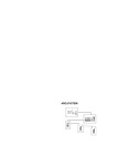
USER MANUAL POWER 6-3 EM POWER 6-3 EM (HALL L.) Index 1. General description............................................................................. 3 1.1.Characteristics ......................................................................... 4 1.2.Technical data ......................................................................... 5 2. Dimensions......................................................................................... 6 3. Installation .......................................................................................... 7 4. Connection ......................................................................................... 9 4.1.Power supply connection ......................................................... 9 Power 6-3 EM – Three-phase power supply ...................... 10 Power 6-3 EM – Single-phase power supply ..................... 11 Power 6-3 EM HALL LIGHTING – Three-phase power supply with individual neutrals ........................................... 11 4.2.Channel connection ............................................................... 12 4.3.DMX connection .................................................................... 12 4.4.PANIC connection ................................................................. 14 5. Programming .................................................................................... 16 5.1.Configuration ......................................................................... 17 Channel configuration........................................................ 17 Local mode configuration................................................... 19 PANIC configuration .......................................................... 19 Chaser configuration.......................................................... 20 5.2.Testing................................................................................... 21 Frequency test................................................................... 21 DMX test............................................................................ 21 Manual test ........................................................................ 22 5.3.System................................................................................... 22 5.4.Unit information...................................................................... 23 Channel information........................................................... 23 System menu..................................................................... 23 Version menu .................................................................... 23 6. Maintenance ..................................................................................... 24 6.1.Regular cleaning.................................................................... 24 7. Most common problems.................................................................... 25 Statement of compliance ....................................................................... 26 User Manual POWER 6-3 EM and POWER 6-3 EM (HALL L.) 2 1. General description Power 6-3 EM and Power 6-3 EM HALL LIGHTING have been developed for working in fix installations where power must be decentralized. They are 6-channel dimmer of 3 kW per channel which include an LCD display for independent level adjustment of each channel. They can work autonomously without control signal. Power 6-3 EM HALL LIGHTING differs from Power 6-3 EM in the fact that incorporates a power supply with three-independent neutral to protect separately the three phases and to avoid total turn off in case of one-phase failure. For this reason, Power 6-3 EM HALL LIGHTING is ideal for controlling hall light installations and complies with the current legislation. They are manufactured for being fixed to a wall, taking up minimum space. Optionally, Panic module can be adapted. Its function is to activate a particular lighting state, which is programmable, for emergency situations. User Manual POWER 6-3 EM and POWER 6-3 EM (HALL L.) 3 1.1. Characteristics Control electronics through microprocessor. DMX-512 (1990) digital signal input. Autonomous working mode selecting one of the 4 chasers. Charge curves that can be applied to each channel: Lineal with voltage, lineal with light, fluorescent and on/off. Test function for signal and power checking. Starting function to increase lamps life span. Automatic mains frequency control. Protection against overvoltage. The output charge channels are protected separately by a breaker per channel. DMX channel selection through LCD display in the front side. Optional Panic function for emergency situations. Output to the loads by guide terminals. Load is duly controlled by 40Amp. triacs which are cooled by a black anodised aluminium radiator and a fan. Power 6-3 EM and Power 6-3 EM HALL LIGHTING references are 07000062 and 07000073, respectively. User Manual POWER 6-3 EM and POWER 6-3 EM (HALL L.) 4 1.2. Technical data Minimum load per channel 400V50Hz three-phase 230V 50Hz single-phase 100W Maximum load per channel 3.000W Power supply Total maximum load Output breaker Power Supply wire section Digital control signal 18.000W 16 Amp per channel 6mm* DMX-512 Digital input connector XLR-5 pins Panic signal (optional) Free contact circuit Panic connector (optional) Net weight Dimensions Jack 8,11 Kg. 104x302x440 mm It is recommended to use a 4-pole 63-Amp breaker (preferably type-D curve) in the three-phase 400V power supply input as general protection of the dimmer. We recommend to install a mains circuit breaker of 4 poles, 63 Amp and 0,03 Amp before the switch is tripped. *Supplying 400V III 50Hz User Manual POWER 6-3 EM and POWER 6-3 EM (HALL L.) 5 2. Dimensions Both dimmers have the following dimensions (in mm): Fig.1: Dimmer dimensions User Manual POWER 6-3 EM and POWER 6-3 EM (HALL L.) 6 3. Installation Power 6-3 EM and Power 6-3 EM HALL LIGHTING can be fixed to a wall. It must be taken into account that the place where they are installed must be ventilated for proper heat dissipation. For this reason, it is recommended to leave a minimum distance of 5 cm between the dimmer and the other elements. Fig.2 Once the location is chosen, the front cover must be separated from the rear one. Unscrew both bolts indicated in figure 2. Then, mark the 4 orifices of the rear support, drill them and fasten the unit to the wall (see figure 3). Eventually, place the front cover and screw the 2 bolts indicated in figure 2. Note: If signal and power cables must be located behind the unit, place them before hang the dimmer on the wall User Manual POWER 6-3 EM and POWER 6-3 EM (HALL L.) 7 Fig.3 Power supply connections must be carried out without the front cover. All the connections are through terminals and connectors which are located on the lower side of the unit. User Manual POWER 6-3 EM and POWER 6-3 EM (HALL L.) 8 4. Connection 3 1 2 4 Fig.4:Lower side view 1. Power supply terminals 2. Charge outputs 3. Panic connectors 4. DMX In and Out 4.1. Power supply connection While Power 6-3 EM HALL LIGHTING must be connected to three-phase power supply with neutrals and earth, Power 6-3 EM can be plugged in: Three-phase power supply with neutral (R, S, T and N) and earth with 400V between phases and 230V between any phase and neutral. 230-volt single-phase power supply in which case R, S and T inputs must be connected to the phase. WARNING: In the second case, half the nominal power has not to be exceeded. User Manual POWER 6-3 EM and POWER 6-3 EM (HALL L.) 9 NOTE: It is very important for right working of the power units, to have a good earth connection. In other case, there could be voltage differences that would damage the dimmer. These dimmers are protected against wrong connections as it should be to supply 400V between a phase and neutral. In this case, power unit would not start up and it would display the message OVERVOLTAGE during a few seconds before the unit would stop. Then, you could proceed to connect the unit in the right way and turn it on again. NOTE: The right order of the phases is shown in figure 5. Fig. 5 Power 6-3 EM – Three-phase power supply VRS = VRT = VST = 400V VRN = VTN = VSN = 230V 400V IV 50Hz N S T R Fig. 6 User Manual POWER 6-3 EM and POWER 6-3 EM (HALL L.) 10 Power 6-3 EM – Single-phase power supply VRN = 230V 230V II 50Hz N S T R Fig. 7 Power 6-3 EM HALL LIGHTING – Three-phase power supply with individual neutrals VRN1 = VSN2 = VTN3 = 230V 230V II 50Hz 230V II 50Hz 230V II 50Hz Fig. 8 User Manual POWER 6-3 EM and POWER 6-3 EM (HALL L.) 11 4.2. Channel connection Channels must be connected to their respective guide terminals. Each one has 3 connections: Phase, ground and neutral. Fig. 9 4.3. DMX connection Signal connectors are XLR of 5 pins. Signal control from the control unit must be connected to the DMX IN and the output signal to other elements to the DMX OUT. You must connect an end-of-line resistance in the output of the last serial device in order to avoid signal interferences (see figure 10). The cables should be braided pair, shielded and low capacity, with a type 24AWG (0,2047mm2) minimum calibre and an impedance of 120 Ohms. Please remember that the type of cable significantly conditions any problem that may arise due to parasites coming through the line. Similarly, DO NOT USE shielded cables commonly used for connecting microphones. The cables should be connected in such a way that pin 1 of the male connector coincides with pin 1 of the female one, and in the same way for pins 2 and 3. Pins 4 and 5 are not used. The screen connected to pin 1 should NOT come in contact with the casing of the connector. User Manual POWER 6-3 EM and POWER 6-3 EM (HALL L.) 12 CONSOLE End-of-line resistance DMX line 120Ω ... UNIT 1 UNIT 2 UNIT N SOLDER SIDE Fig.10: Signal connection net The connection should be made exactly as shown in figure 10. You will see that a resistance of 120 Ohms 1/4W has been installed at the end of the line between pins 2 and 3. This corresponds to the end-of-line connector supplied with all projectors. A maximum of 32 projectors may be linked up to a single line without using an amplifier. And the maximum cable length as far as the last projector is 1 Km, although it is advisable to use an amplifier for cables every 500 meters. DMX line CONSOLE WRONG CONNECTION! UNIT 1 UNIT 3 SOLDER SIDE UNIT 2 120Ω UNIT 4 ... ... UNIT N End-of-line resistances UNIT P Fig.11: Wrong connection User Manual POWER 6-3 EM and POWER 6-3 EM (HALL L.) 13 Connection shown in figure 11 is INCORRECT. If an installation divided into several branches is required, splitters must be used. They distribute and amplify a single signal into several identical ones in different lines (see Figure 12). CONSOLE RIGHT CONNECTION DMX line SPLITTER UNIT 1 UNIT 3 SOLDER SIDE UNIT 2 UNIT 4 120Ω ... ... UNIT N UNIT P End-of-line resistances Fig.12: Right connection 4.4. PANIC connection PANIC function connection is carried out through a Jack stereo connector situated near DMX connectors (see figure 4). Its connection only requires two cables connected to Jack connector as shown in figure 13. Activating switch for PANIC function Fig.13: Jack connection (PANIC function) User Manual POWER 6-3 EM and POWER 6-3 EM (HALL L.) 14 PANIC function is available by means of a free contact circuit. Thus, connecting PANIC signal to a switch, function will be activated when pressing it. IMPORTANT: Activation of this function has to be by means of a switch, not with a button. There is an input and output Jack connector to propagate the signal to other units. User Manual POWER 6-3 EM and POWER 6-3 EM (HALL L.) 15 5. Programming The following table shows a map of the dimmer menus and its options. You can move on the menus pressing “+” and “-” and select an option pressing “store”. (Start up) CONFIG: CHANNEL: LOCAL: LOCAL: PANIC: CHASE: TEST: FREQ: DMX: MANUAL: SYSTEM: INFO: CHANNEL: SYSTEM: VERSION: User Manual POWER 6-3 EM and POWER 6-3 EM (HALL L.) 16 When the dimmer is starting up, it displays these messages: 5.1. Configuration To start with the configuration, you must enter to CONFIG menu. You can move on the menus pressing “+” and “-” and select an option pressing “store”. Once there, you can select among three options: channels, chasers and local mode. Channel configuration Select CHANNEL to configure the channels. In this menu, you have two options: channel-per-channel configuration or all channels together. XXX: It becomes “ALL” when configuring all the channels together or, alternatively, shows numbers from 1 to 6. In the former case, parameterization (maximum, minimum, response curves, etc.) will be equal for all the channels, which starting by the first User Manual POWER 6-3 EM and POWER 6-3 EM (HALL L.) 17 channel will increase in one until the end of the total amount of channels of the dimmer. When configuring the channels, either together or channel-per-channel, there will be this message: YYY: Define the type of response curve. LIN V – linear with voltage LIN L - linear with light FLUO – fluorescent ON-OFF – Everything or nothing XX: Address DMX channel to this dimmer channel. MX: Maximum output value from 0 to F (100%). MN: Minimum output value L: Channel value when working in local or PANIC mode. For validating each option, you must press “store”. If you configure channel-per-channel, this process must be repeated for each channel. On the contrary, dimmer channels will be configured with the same options with the exception of the address. User Manual POWER 6-3 EM and POWER 6-3 EM (HALL L.) 18 Local mode configuration To start this configuration, you must enter to LOCAL menu after selecting CONFIG. Then, select local and eventually you can select ON for activating local mode or OFF for deactivating it. When working in local mode, channel values will be the ones configured before (see Channel configuration). Press “store” for validating the selection. PANIC configuration The sequence of selections to go to Panic menu is: CONFIG – LOCAL – PANIC. Then, pressing “ON” is activated. From now on, if a Panic signal is received through the jack connector located in the lower internal side of the dimmer (see PANIC connection), automatically all the channels will be activated with the previously configured values in the local mode (see Local mode configuration). User Manual POWER 6-3 EM and POWER 6-3 EM (HALL L.) 19 Panic signal consists of a free contact which opens or closes a circuit from an architectural lighting system or any other element which can carry out the same function (e.g. emergency stop). Chaser configuration First of all, you must enter to CHASER menu: XXX: There are five options: “OFF” (chaser disconnected) or from 1 to 4 (different chasers). Pressing “+” and “-”, you can select one of the 4 predefined chasers and then define FADE and TIME times which are from 0 to 8 minutes and 0 to 59 seconds, respectively. User Manual POWER 6-3 EM and POWER 6-3 EM (HALL L.) 20 5.2. Testing This menu is for changing the output level of each channel and verifying the state of the inputs and outputs: DMX input and mains frequency. Frequency test X: It indicates mains frequency value. Y: It is “OK” if the signal is synchronised with the other phases and “Rf” for the phase used as reference. If there is no synchronism, it will be “?”. DMX test This menu shows the DMX state and any data losing. When DMX is not detected, it will show this message: If DMX signal is received: XX: Number of channels received. User Manual POWER 6-3 EM and POWER 6-3 EM (HALL L.) 21 ZZ: Number of packs received per second. Y: If there is any error when receiving packs. Manual test This menu enables you to change manually channel level. The output level can be selected from 0 to F. X: Number of channel to modify. Y: Output level from 0 to F (0-100%). 5.3. System This menu has three options: unit initialization, unit restoration and keyboard blockage. BLOCK: The four buttons are blocked. Press them altogether to unblock it. INIT: The power unit is initialized with default values. RESTART: Keeping the programmed parameters of the configuration, the power unit will be reset. User Manual POWER 6-3 EM and POWER 6-3 EM (HALL L.) 22 5.4. Unit information This is a menu which informs about the state of the different parameters of the dimmer, there are three options: channel information, system menu and version menu. Channel information It shows the state of each channel. System menu This is an information menu; consequently, no parameters can be modified. If the power unit works in automatic mode (chasers), it will show the times of FADE and TIME. It will also show local mode state: on or off. Version menu It informs about the software version of the dimmer. POWER 6-3 EM User Manual POWER 6-3 EM and POWER 6-3 EM (HALL L.) 23 6. Maintenance 6.1. Regular cleaning To prevent the growth of dust and dirt which may impair the proper operation of the equipment, it should be cleaned regularly. For cleaning it, use a soft, slightly and damp cloth (if the equipment is very dirty, apply a little liquid detergent to the cloth). WARNING: Do not use solvents or products containing alcohol. Make sure that no liquid get inside the equipment. User Manual POWER 6-3 EM and POWER 6-3 EM (HALL L.) 24 7. Most common problems Problem Usual cause Solution Unit does not start No current reaching the unit Check mains connections Power unit does not give response in some channels Breakers or differentials activated Check breakers and differentials state Addressing problem Address channels in free addresses See “Programming” section The unit does not work in autonomous mode PANIC function does not respond Wrong DMX line installation Check the type of cable, connections, connectors, installation and 120Ω terminator resistance No chaser selected See “Programming” section No FADER and TIMER selected See “Programming” section Not activated or not programming See “Programming” section Wrong jack connection Check connection See “Connection” section If the problem persists despite these measures, please contact to FRESNEL’s Technical Service Department. Telf +34 93 274 54 28 Telf +34 93 360 02 30 Fax +34 93 274 47 47 If you want to do without this product, do not mix it with the ordinary waste. There are specific methods and systems for dividing electronic and electromagnetic used products that are described in 2002/96/EC directive, which is in force in the European Community countries. User Manual POWER 6-3 EM and POWER 6-3 EM (HALL L.) 25 FRESNEL S.A. DC-01 STATEMENT OF COMPLIANCE DATE: 01/01/12 We declare that the products: Mark: STRONG Models: POWER 6-3 EM POWER 6-3 EM HALL LIGHTING Year of construction: 2012 Conforms to the following EC directives: 2006/95/EC: In relation to the safety requirements for material intended for use within specific voltage limits. 2004/108/EC: In relation to the electromagnetic compatibility of equipment, systems and installations. Sole administrator Ángel Torrecillas Redón Barcelona, January 1st of 2012 Fresnel S.A. C/ Potosí 40 08030 Barcelona Spain Tel: +34 93 360 02 30 Fax: +34 93 274 47 47 [email protected] http://www.strong.es User Manual POWER 6-3 EM and POWER 6-3 EM (HALL L.) 26