1
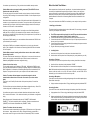
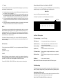
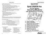
5. Online Technical Support
Model: FM-VSP56E2
If you have access to the World Wide Web be sure to visit the Zoltrix home page at:
Quick Installation Reference Card
http://www.zoltrix.com
You may also want to read the updated Modem Questions and Answers located at:
http://www.zoltrix.com/modem-qa.htm
You may also locate the complete AT commands and Windows 95 drivers from the following
page:
http://www.zoltrix.com/modem.htm
You may also locate the Technical Support phone numbers and e-mail addresses on the
Tech Support Web page at:
Rainbow 56K
http://www.zoltrix.com/techsupp.htm
External V.90 Fax/Modem
with
Speaker Phone Functions
56,000 bps Data
þ
þ
þ
þ
þ
þ
þ
3QF-56KVSPE2
115,200 bps Throughput
V.90/K56Flex 56,000 bps Data Modem
14,400 Send & Receive Fax
MNP2-4 & V.42 Error Correction &
MNP5 & V.42bis Data Compression
Full Featured Voice Messaging
Full Duplex Speakerphone Functions
2 Mega Byte Flash ROM Equipped
Leading the world in fax/modem technology
V.90 56 kbps High Speed External
Voice/Fax/Speaker Phone Modem
answers after two rings).
Problem: The modem always answers the phone
Set the S0 register to 0. ATS0=0
In addition to high speed fax and data transfer functions your fax/modem supports the following
additional voice features giving you a personal voice messaging system with speakerphone,
perfect for the home or small business:
•
Automatically detect and route incoming voice, fax and data calls to the proper module of
integrated fax, data and voice software packages that support Rockwell-based Voice Fax/
Modems.
•
•
•
•
•
•
Create up to 999 voice mailboxes, each with a personal mailbox greeting message.
•
•
Call from a remote location with a touch tone telephone to retrieve messages.
Listen to voice messages through the telephone handset or amplified speakers.
Record your own greeting messages for each mailbox.
Monitor incoming calls and answer the calls at your own convenience.
Password-protection for each mailbox.
Log of received incoming messages for each mailbox displaying status, date and time
received, assigned record number, duration and file size of each message.
Call your pager to notify you of received messages.
Speaker Phone
•
Turns your computer into a full-functioned speaker phone (speakers and microphone
required)
•
•
•
•
•
Places and answers telephone calls directly from your computer
Features mute, redial, hold, pause and clear functions
Problem: The communications software displays, "No Dialtone".
Make sure that your phone cable is working properly and that it is firmly seated to the phone
socket at your phone jack and in the rear panel of the modem.
The External Modem Features
Hardware Features
•
56,000 bps maximum Data reception / 33,600 bps maximum transmission
•
14,400 bps Send and Receive Fax
•
DTE Rates up to 115,200 bps with Automatic Speed Conversion to DCE speed
•
Non-Volatile memory stores 4 phone numbers and 2 user defined configurations
•
Touch tone and pulse dialing
•
On board speaker to monitor Call Progress
•
Automatic Call Progress Monitoring, Dial Tone, Busy Signal and Ring Result provided
•
•
•
•
•
•
•
Direct dialing from your computer keyboard
Phonebook with speed dialing access
Software volume control
Modem Installation
Necessary Equipment
In addition to the External Fax/modem and its wall mount power supply, make sure that
you have all of the following equipment at hand before you begin:
• An IBM PC/386/486/Pentium or compatible computer with an available serial port
• A modular telephone cable (included)
• A modular telephone outlet
• A 9-pin to 9-pin and 25-pin RS232D Serial Cable (included)
• A telephone set (Optional)
• A condenser Microphone (Optional)
• An amplified magnetically shielded speaker (Optional)
•
•
•
for communications software response
Operates with computers via standard Asynchronous RS-232 Serial Port
V.42bis and MNP5 Data Compression
V.42 and MNP2-4 Error Correction
Supported by Standard AT Command Set
Supported by Enhanced AT Command Set
Supports Class 1 Fax Commands
Adaptive Differential Pulse Coded Modulation (ADPCM) to compress voice message
for maximum storage optimization
Silence Detection for further compression of voice message files
Supported Sampling Rate: 7200 sample per second with 2 or 4 or 8 bits per sample
Flash ROM for firmware update and feature enhancement
Hardware Compliance
•
ITU-T V.90 or K56Flex, V.34, V.32bis, V.32, V.22bis, V.22, V.21 and Bell 103
•
56,000, 33600, 28800, 14400, 9600, 2400, 1200 and 300 bps Data Transmission
•
ITU-T V.42bis Data Compression
•
MNP5 Data Compression
•
ITU-T V.42 Error Correction
•
MNP2-4 Error Correction
•
Asynchronous RS-232
•
Group 3 Fax : ITU-T V.17, V.29, V.27ter, V.21 Channel 2
•
Class 1 Fax Commands
•
FCC Part 15, Part 68
•
Capable of receiving at up to 56kbps, and send at up to 31.2kbps. Due to FCC
regulations on power output, receiving speeds limited to 53kbps. Actual speeds vary.
Requires compatible phone line and server equipment. Complies with both the V.90
56k standard and K56Flex technology protocols.
Your modem may need servicing. Call your dealer about available warranty services.
Before You Install Your Modem...
Problem: Modem does not respond to dialing commands (TD and RD LED's do not
illuminate and modem will not dial.)
This may be a result of a loose cable connection, using an improper or faulty serial cable or
from wrong COM Port settings in the communications software or in the computer serial port
configurations.
Most computers have 2 serial ports and 1 parallel ports. An external modem requires that
one serial port is enabled and recognized by the computer. Unless you are using a bus
mouse, serial port #1 is usually where you will install your mouse or other pointing device.
Serial port #2 is usually where you would install an external modem. Please refer to the
hardware Manual for instructions on Determining What Serial Ports Are Installed In Your
Computer.
Check that all cable connections are secure. Verify that the serial cable is firmly seated in the
connectors on your computer and on the modem. You may also wish to verify that the serial
port cable within your computer is also firmly seated and properly oriented to the serial port
connector on the I/O card or on the motherboard.
Verify that you are using the proper cable. You should use one of the following shielded
cable types: 25-pin to 9-pin (if your computer has a 25-pin connector at the serial port you
wish to use) or a straight 9-pin to 9-pin serial cable (if your computer has a 9-pin connector at
the serial port you wish to use).
Verify that the COMPort setting in your communication software matches the COM Port that
you've selected on your computer.
Once you've determined which COMPort is available, you are ready to install your modem.
1. Installing your fax/modem
The steps to install your modem are shown in order in this section. For some steps, you may need
to refer to your computer’s User’s Manual.
A.
B.
C.
D.
Verify that the COMPort you've selected is enabled and is not in use by any other serial
device. Refer to Appendix A for information on Determining What Serial Ports Are Installed
On Your Computer.
Problem: Modem answers incoming calls and then returns to the on-hook condition,
disconnecting the caller.
This occurs most often when connecting to a UNIX system. In most case, the host does not
prefer to see any result or command echo codes. If this is the case, the codes can be
disabled by adding E0 Q1 to the modem configuration string.
Problem: No echo from modem
This is normally caused by an I/O address or IRQ conflict. Verify that the COMPort is not in
use by any other serial device and if necessary use another COMPort or I/O address setting.
Refer to Appendix A for information on Determining What Serial Ports Are Installed On Your
Computer. You may also need to refer to your computer or I/O card hardware manual.
E.
2.
A.
B.
Turn OFF the computer before you begin. Also, turn OFF any external devices that are
connected to your computer, such as printers, monitors, etc...
Connect the male end of the 9-pin RS232D serial cable to the modem's Serial Port.
Connect the other end of the RS232D cable into a 9-pin or 25-pin serial port connector on
the rear panel of your computer.
Connect the wall-mount power supply (provided with the modem) to the power connector
on the rear panel of the modem.
Plug the wall-mount power supply into the AC wall socket.
Installing Cables
Insert one end of the phone line into the jack on the modem labeled “Line“.
Insert the other end of the phone line into the phone jack, (usually located on your wall).
Connecting a Telephone
If you wish to use a phone set in conjunction with your modem, please follow these steps:
A.
B.
Insert the line from the phone into the jack labeled “PHONE”.
Make sure that the other end of the phone line is connected to the telephone.
Note: With the modem and phone sharing a single phone line, your phone will function as normal.
However, while the modem is in use (ie. the modem is off-hook, and the CD/OH LED is
illuminated), you will not be able to dial out or receive any calls.
Problem: The modem dials and appears to complete the connection, but the
communications software does not enter the correct mode. (The screen remains
blank.)
There may be an I/O conflict (See the solution for the previous problem, "No echo from
modem").
Connecting a Microphone
If you wish to use a microphone to record the greeting message or for use with the speaker phone,
please follow these steps:
The Result Codes may have been disabled by the software configuration set up. Check if Q1
is in the configuration or initialization string. If so, change it to Q0.
Connecting Speakers
If you wish to listen to the recorded voice message with speaker, please follow these steps:
Your software may require numeric result codes rather than verbal result codes. Use either
V0 for numeric result codes or V1 for verbal result codes in your initialization or configuration
string.
A.
or
B.
Some software require full extended result codes (ie. CONNECT 14400 instead of
CONNECT). This can be controlled by the Xn command. X0 sends a summarized code
(CONNECT) and X4 sends a full extended code (CONNECT 14400).
Problem: The modem does not auto answer.
The auto answer mode is determined by the S0 register. If S0 has been set to 0, the modem
will not answer. Assign another value to S0 by entering the following command S0=n,
where n=the number of rings to occur before the call is answered (ATS0=2, the modem
A.
Using a condenser microphone with a 1/8" plug, install the plug into the jack labeled "MIC".
Using speakers with a 1/8" stereo plug, install the plug into the jack labeled "SPK".
Using an audio cable with a 1/8" stereo plug at both ends, connect one end to the jack labeled
"SPK" and the other end into your sound cards line-in jack. This will allow you to control the
volume with the sound cards line-in software volume control.
AC 12 V
SERIAL PORT
SPK
MIC
PHONE LINE
3.
Testing
The actual installation of the modem is now complete. Before attempting to use your modem, you
should complete the following steps:
A.
B.
C.
D.
Check that all phone cords are firmly connected. Lift the handset of the telephone to check
for a dial tone. Turn your computer on.
Turn the modem on by depressing the ON/OFF button located on the top of the modem near
the upper right corner of the front panel. You should see the TM, HS, TR and PWR LED's
illuminate. The TM and TR buttons will illuminate briefly and will go dim after a second.
You’ve now completed the hardware installation of your modem. From here, you are ready
to install the communications software. Please refer to the software installation section for
instructions.
Once you’ve installed your communications software, you‘ll be ready to test the modem
according to the instructions in either the hardware or software manual.
Software Settings for Windows 3.1x to Enable the 16550 UART
To enable the use of the UART, you must edit the SYSTEM.INI file in your Windows directory.
Add the following line to your SYSTEM.INI file under the [386enh] section:
COMxFIFO=1
where x = the COM port where the modem is installed.
For example if your modem is set at COM2, the statement would read:
COM2FIFO=1
TM - Test Mode
HS - High Speed
AA
TR- Auto
TM Answer
AA
CD
CD - Carrier Detect
OH - Off Hook
UART's
To ensure that you do not lose data bits at high speed transmissions or while you are running
DOS and Windows programs at the same time, make sure that the serial port where you're
installing the modem has a 16550 compatible UART. Most computers have serial ports with
the 16550 UART unless you have an older system. Serial I/O cards with the 16550 UART are
also available from your computer retailer.
Your modem will still function normally if you do not have a 16550 UART supported serial
port, but you may experience some lost data if you set the communication software's "baud"
rate above 19200 bps.
UART Verification
To verify that you do have a 16550 UART, turn on your computer and load the DOS directory.
C:\>CD DOS
Type MSD at the prompt:
C:\>MSD
After the MSD program, complete its diagnostics, press the C key to display the information on
your computers serial ports. Look down the column of the COMport where you intend to install
your modem. The "UART Used" will be displayed at the bottom of the column.
If it reads 16550, 16550A, 16550AF, 16550B, etc... install your modem at that serial port.
OH
On/Off Switch
TD
TD - Transmit Data
RD - Receive Data
TR - PW
Terminal Ready
RD
PW - Power
Front Panel LED Descriptions
TR (Terminal Ready) - Lit when DTR is high.
T M (Test Mode)
- Lit during test mode, flashes once during power up.
AA (Auto Answer)
- Lit when Auto-answer mode is enabled, flashes when an
incoming call has been detected.
- Lit when a valid carrier has been detected from the remote
modem.
- Lit when the modem is in the Off Hook mode.
CD (Carrier Detect)
OH (Off Hook)
TD (Transmit Data)
RD (Receive Data)
PW (Power)
- Flashes when data is being transmitted from your computer to
the modem.
- Flashes when data is being received by your computer from the
modem.
- Lit when modem is powered.
Note: All status LED's are red with the exception of the PW LED which is green.
Troubleshooting
The following lists the most common problems encountered when an installation is unsuccessful. By reading it through carefully you may be able to resolve any problems yourself.
Problem: Modem LED's are not lit.
Verify that the modem power switch is on, the power adapter is firmly seated at the AC wall
outlet and at the power connector in the rear panel of the modem.
Problem: The TM (Test Mode) LED flashes continuously.