1
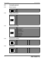
MITSUBISHI ELECTRIC
HMI
Industrial Panel PCs
IPC Terminals
Users Manual
IPC-MC1121, IPC-MC1151
Art. no.:
10 03 2009
Version A
MITSUBISHI ELECTRIC
INDUSTRIAL AUTOMATION
User’s Manual
IPC-MC1000
Art no:
A
Version
04/2009 pdp - rw
Revisions / Additions / Corrections
First edition
About This Manual
The texts, illustration, diagrams and examples in this manual are provided
for information purposes only. They are intended as aids to help explain the
installation, operation, programming and use of the
IPC-Terminals IPC-MC1000.
If you have any questions about the installation and operation of any of the
products described in this manual please contact your local sales office or distributor (see back cover).
You can find the latest information and answers to frequently asked questions on our website at
www.mitsubishi-automation.com.
MITSUBISHI ELECTRIC EUROPE BV reserves the right to make changes
to this manual or the technical specifications of its products at any time without notice.
© 04/2009
Safety Guidelines
Safety Guidelines
General safety information and precautions
For use by qualified staff only
This manual is only intended for use by properly trained and qualified electrical technicians who are
fully acquainted with the relevant automation technology safety standards. All work with the
hardware described, including system design, installation, configuration, maintenance, service and
testing of the equipment, may only be performed by trained electrical technicians with approved
qualifications who are fully acquainted with all the applicable automation technology safety
standards and regulations. Any operations or modifications to the hardware and/or software of our
products not specifically described in this manual may only be performed by authorised Mitsubishi
Electric staff.
Proper use of the products
The IPC-Terminals IPC-MC1121 and IPC-MC1151 are only intended for the specific applications
explicitly described in this manual. All parameters and settings specified in this manual must be
observed. The products described have all been designed, manufactured, tested and documented in
strict compliance with the relevant safety standards. Unqualified modification of the hardware or
software or failure to observe the warnings on the products and in this manual may result in serious
personal injury and/or damage to property. Only peripherals and expansion equipment specifically
recommended and approved by Mitsubishi Electric may be used with the IPC-Terminals IPC-MC1121
and IPC-MC1151.
All and any other uses or application of the products shall be deemed to be improper.
Relevant safety regulations
All safety and accident prevention regulations relevant to your specific application must be observed
in the system design, installation, configuration, maintenance, servicing and testing of these
products. The regulations listed below are particularly important in this regard. This list does not claim
to be complete, however; you are responsible for being familiar with and conforming to the
regulations applicable to you in your location.
● VDE Standards
– VDE 0100
Regulations for the erection of power installations with rated voltages below 1000 V
– VDE 0105
Operation of power installations
– VDE 0113
Electrical installations with electronic equipment
– VDE 0160
Electronic equipment for use in power installations
– VDE 0550/0551
Regulations for transformers
– VDE 0700
Safety of electrical appliances for household use and similar applications
– VDE 0860
Safety regulations for mains-powered electronic appliances and their accessories for
household use and similar applications.
HMI IPC Terminals
I
Safety Guidelines
● Fire safety regulations
● Accident prevention regulations
– VBG Nr.4
Electrical systems and equipment
Safety warnings in this manual
In this manual warnings that are relevant for safety are identified as follows:
P
DANGER:
E
WARNING:
REMARK
Failure to observe the safety warnings identified with this symbol can result in health and injury
hazards for the user.
Failure to observe the safety warnings identified with this symbol can result in damage to the
equipment or other property.
This indicates general information about the product and the user manual.
This indicates detail information about the specific product configuration.
This precedes helpful hints and tips for daily use.
II
Safety Guidelines
FCC Statement
This equipment has been tested and found to comply with the limits for a Class A digital device,
pursuant to Part 15 of the FCC Rules. These limits are designed to provide reasonable protection
against harmful interference when the equipment is operated in commercial environment. This
equipment generates, uses, and can radiate radio frequency energy and, if not installed and used in
accordance with the instruction manual, may cause harmful interference to radio communications.
Operation of this equipment in residential area is likely to cause harmful interference in which case
the user will be required to correct the interference at his own expense.
CE-CONFORMITY
The following requirements, standards, specifications constitute part of the declaration:
● EN 55022 class A
● EN 55024
● EN 60950-1
● EN 61000-3-2
● EN 61000-3-3
● EN 61000-6-2
The validation of this declaration depends on the properly use of the product.
HMI IPC Terminals
III
Safety Guidelines
Specific safety information and precautions
The chapter also contains information on approval and interference suppression of your device.
Observe the warnings and instructions on the device and in the manual. The device has been built and
tested in accordance to EN 60950-1 and left the company in a perfectly safe condition. In order to
maintain this condition and ensure safe operation, the user must observe the instructions and
warnings contained in this manual.
P
DANGER:
● The device must be used in accordance with the instructions for use.
● The electrical installations in the room must correspond to the requirements of the respective
regulations.
● Take care that there are no cables, particularly power cables, in areas where persons can trip
over them.
● Take care that there are no cables, particularly power cables, in areas where persons can trip
over them.
● Only use the power cord supplied.
● Only devices and components which fulfill the requirements of an SELV circuit (safety extra
low voltage) in accordance with EN60950 may be connected to the interfaces of the system.
● All plugs on the connection cables must be screwed or locked to the housing.
● The device is designed to be used in vertical position with the interfaces downwards.
● Repairs may only be carried out by a person authorized by Mitsubishi Electric.
● Maintenance or repair on the open device may only be done out by qualified personnel
authorized by Mitsubishi Electric which is aware of with the associated dangers.
● The device may only be opened for the installation and removal of PCI cards in accordance
with the description in this manual. These procedures have to be carried-out only by qualified
specialist personnel.
● If extensions are made to the device the legal stipulations and the device specifications must
be observed.
● The device must be switched off before installation and removal of any PCI and CompactFlash™ cards.
● Only original accessories approved by Mitsubishi Electric may be used.
● It must be assumed that safe operation is no longer possible, if the device has visible damage
or if the device no longer functions. In these cases the device must be shut down and secured
against unintentional operation.
● The DC-input must fulfill SELV requirements of EN60950-1 standard.
● DC/DC-supplies do not fulfill the requirements for centralized DC power systems as required
for use in the USA.
IV
Safety Guidelines
Electrostatic Discharge (ESD)
A sudden discharge of electrostatic electricity can destroy static-sensitive devices or micro-circuitry.
Therefore proper packaging and grounding techniques are necessary precautions to prevent
damage. Always take the following precautions:
E
WARNING:
● Transport boards in ESD-safe containers such as boxes or bags.
● Keep electrostatic sensitive parts in their containers until they arrive at the ESD-safe workplace.
● Always be properly grounded when touching a sensitive board, component, or assembly.
● Store electrostatic-sensitive boards in protective packaging or on antistatic mats.
Grounding Methods
The following measures help to avoid electrostatic damages to the device:
E
WARNING:
● Cover workstations with approved antistatic material. Always wear a wrist strap connected
to workplace as well as properly grounded tools and equipment.
● Use antistatic mats, heel straps, or air ionizers for more protection.
● Always handle electrostatic sensitive components by their edge or by their casing.
● Avoid contact with pins, leads, or circuitry.
● Turn off power and input signals before inserting and removing connectors or connecting
test equipment.
● Keep work area free of non-conductive materials such as ordinary plastic assembly aids and
Styrofoam.
● Use field service tools such as cutters, screwdrivers, and vacuum cleaners which are conductive.
● Always place drives and boards PCB-assembly-side down on the foam.
HMI IPC Terminals
V
Safety Guidelines
Instructions for the Lithium Battery
The device is equipped with a lithium battery.
E
VI
WARNING:
There is a danger of explosion if the wrong type of battery is used for replacement. Replace only
with the same or equivalent type of battery as recommended by the manufacturer. Dispose of
used batteries according to the manufacturers instructions.
Table of Contents
Table of Contents
1
Introduction
1.1
Appropriate use. . . . . . . . . . . . . . . . . . . . . . . . . . . . . . . . . . . . . . . . . . . . . . . . . . . . . . . . . . . . . . . . . . . . . . . . 1-1
1.2
Item Checklist. . . . . . . . . . . . . . . . . . . . . . . . . . . . . . . . . . . . . . . . . . . . . . . . . . . . . . . . . . . . . . . . . . . . . . . . . . 1-1
2
Overview
3
Hardware installation
3.1
Installation / Mounting . . . . . . . . . . . . . . . . . . . . . . . . . . . . . . . . . . . . . . . . . . . . . . . . . . . . . . . . . . . . . . . . . 3-2
3.2
3.1.1
Mount IPC-MC1121. . . . . . . . . . . . . . . . . . . . . . . . . . . . . . . . . . . . . . . . . . . . . . . . . . . . . . . . . . . . 3-2
3.1.2
Mount IPC-MC1151. . . . . . . . . . . . . . . . . . . . . . . . . . . . . . . . . . . . . . . . . . . . . . . . . . . . . . . . . . . . 3-2
Connect external devices . . . . . . . . . . . . . . . . . . . . . . . . . . . . . . . . . . . . . . . . . . . . . . . . . . . . . . . . . . . . . . . 3-3
4
Software Installation
4.1
Application software and operating system . . . . . . . . . . . . . . . . . . . . . . . . . . . . . . . . . . . . . . . . . . . . . 4-1
4.2
Hardware drivers . . . . . . . . . . . . . . . . . . . . . . . . . . . . . . . . . . . . . . . . . . . . . . . . . . . . . . . . . . . . . . . . . . . . . . . 4-1
4.2.1
4.2.2
4.2.3
4.2.4
Install Touch driver . . . . . . . . . . . . . . . . . . . . . . . . . . . . . . . . . . . . . . . . . . . . . . . . . . . . . . . . . . . . 4-2
Windows touch calibration procedure . . . . . . . . . . . . . . . . . . . . . . . . . . . . . . . . . . . . . . . . . 4-4
LINUX touch calibration procedure . . . . . . . . . . . . . . . . . . . . . . . . . . . . . . . . . . . . . . . . . . . . 4-5
Fieldbus driver installation. . . . . . . . . . . . . . . . . . . . . . . . . . . . . . . . . . . . . . . . . . . . . . . . . . . . . 4-5
5
Technical details
5.1
Mechanical . . . . . . . . . . . . . . . . . . . . . . . . . . . . . . . . . . . . . . . . . . . . . . . . . . . . . . . . . . . . . . . . . . . . . . . . . . . . 5-1
5.2
Electronical . . . . . . . . . . . . . . . . . . . . . . . . . . . . . . . . . . . . . . . . . . . . . . . . . . . . . . . . . . . . . . . . . . . . . . . . . . . . 5-1
5.3
Environment . . . . . . . . . . . . . . . . . . . . . . . . . . . . . . . . . . . . . . . . . . . . . . . . . . . . . . . . . . . . . . . . . . . . . . . . . . . 5-1
5.4
CE directives and standards . . . . . . . . . . . . . . . . . . . . . . . . . . . . . . . . . . . . . . . . . . . . . . . . . . . . . . . . . . . . 5-1
5.5
Connector pinout . . . . . . . . . . . . . . . . . . . . . . . . . . . . . . . . . . . . . . . . . . . . . . . . . . . . . . . . . . . . . . . . . . . . . . 5-2
5.6
5.5.1
Power Connector. . . . . . . . . . . . . . . . . . . . . . . . . . . . . . . . . . . . . . . . . . . . . . . . . . . . . . . . . . . . . . 5-2
5.5.2
Fieldbus CAN interface . . . . . . . . . . . . . . . . . . . . . . . . . . . . . . . . . . . . . . . . . . . . . . . . . . . . . . . . 5-2
5.5.3
RS232 Connector COM1 . . . . . . . . . . . . . . . . . . . . . . . . . . . . . . . . . . . . . . . . . . . . . . . . . . . . . . . 5-2
5.5.4
Network LAN 1 interface . . . . . . . . . . . . . . . . . . . . . . . . . . . . . . . . . . . . . . . . . . . . . . . . . . . . . . . 5-2
5.5.5
USB interface. . . . . . . . . . . . . . . . . . . . . . . . . . . . . . . . . . . . . . . . . . . . . . . . . . . . . . . . . . . . . . . . . . 5-2
5.5.6
VGA interface . . . . . . . . . . . . . . . . . . . . . . . . . . . . . . . . . . . . . . . . . . . . . . . . . . . . . . . . . . . . . . . . . 5-3
5.5.7
Reset switch. . . . . . . . . . . . . . . . . . . . . . . . . . . . . . . . . . . . . . . . . . . . . . . . . . . . . . . . . . . . . . . . . . . 5-3
5.5.8
Grounding point . . . . . . . . . . . . . . . . . . . . . . . . . . . . . . . . . . . . . . . . . . . . . . . . . . . . . . . . . . . . . . 5-3
Block diagram. . . . . . . . . . . . . . . . . . . . . . . . . . . . . . . . . . . . . . . . . . . . . . . . . . . . . . . . . . . . . . . . . . . . . . . . . . 5-4
6
Maintenance
6.1
Customer service. . . . . . . . . . . . . . . . . . . . . . . . . . . . . . . . . . . . . . . . . . . . . . . . . . . . . . . . . . . . . . . . . . . . . . . 6-1
6.2
Cleaning . . . . . . . . . . . . . . . . . . . . . . . . . . . . . . . . . . . . . . . . . . . . . . . . . . . . . . . . . . . . . . . . . . . . . . . . . . . . . . . 6-1
6.3
Returning Defective Material . . . . . . . . . . . . . . . . . . . . . . . . . . . . . . . . . . . . . . . . . . . . . . . . . . . . . . . . . . . 6-2
7
Troubleshooting
7.1
FAQ . . . . . . . . . . . . . . . . . . . . . . . . . . . . . . . . . . . . . . . . . . . . . . . . . . . . . . . . . . . . . . . . . . . . . . . . . . . . . . . . . . . 7-1
8
Disposal
9
Appendix
9.1
Illustration contents . . . . . . . . . . . . . . . . . . . . . . . . . . . . . . . . . . . . . . . . . . . . . . . . . . . . . . . . . . . . . . . . . . . . 9-1
HMI IPC Terminals
VII
Table of Contents
VIII
Appropriate use
Introduction
1
Introduction
1.1
Appropriate use
The main purpose of the MicroClient is the use and operation with 24 V DC power sources.
The surrounding area are dry rooms. The Panel is intended for industrial applications in machine and
plant control engineering. The user is not entitled to change the system components or open the
body without consultation to Mitsubishi Electric.
1.2
Item Checklist
Your Micro Client comes securely packaged in solid shipping carton(s). Upon receiving your system,
open the carton(s) and remove the contents carefully. The shipping carton should contain the following items:
– IPC-MC1121 or IPC-MC1151
– CPU Support CD (optional)
– 24 V DC Power cord (optional)
– This user manual (optional)
– Software installation CD if implemented
Carefully inspect each component to ensure that nothing is missing and/or damaged. If any of these
items is missing or damaged, please contact Mitsubishi Electric immediately. Preserve of of the pakking material for future transportation.
HMI IPC Terminals
1-1
Introduction
1-2
Item Checklist
Overview
2
Overview
Mitsubishi Electric MicroClients (Thin Clients) used as web-based display and operator panels with all
the application programs running on a central web server are very low-maintenance and also highly
flexible. The advantages of this thin client architecture include centralized administration and software
maintenance, maximum data security through centralized data storage and backup, and high reliability and availability (high MTBF values) through the elimination of rotating mass storage devices and
fans, which reduces the total cost of ownership to the minimum.
Designed to meet the performance requirements of visualization and communications over ethernet, the new IPC-MC1121 and IPC-MC1151 have high-performance ETX-based x86 CPU modules that
can be scaled inexpensively to meet changing performance needs. The innovative fanless cooling
concept allows for a compact, spacesaving system. Shock and vibration resistance, thermal stability
and compliance with the strictest EMC standards are standard features for all MicroClients. 24 V DC,
5.4 A is required as external power supply!
Features:
– Scalable display sizes: 12.1" /15“
– Resistive analog touch screen
– X86 processor
– Small depth of <50 mm
– Compact Flash
– CAN bus on board
– Up to 256 MB SDRAM
– Optional: 1x RS 232, 1x LAN, 2x USB
– IP 65 front (NEMA 250 type 12 and 13)
– Power supply: 24 V DC and fanless cooling concept
– Meets toughest industrial requirements
– Windows XP Professional Multilanguage
– All connectors build for industrial standards
– Shock and vibration tested
– Embedded architecture long-life electronic components
HMI IPC Terminals
2-1
Overview
2-2
Hardware installation
3
E
Hardware installation
WARNING:
The weight of the Panel is about 7 kg. Carry it on with both hands!
The MicroClient of this type is developed to work in a control cabinet. Thereby it must be pointed that
all the environmental conditions must be considered. When installing the Panel take care that there
is enough area for ventilations on rear side. For details go to item housing dimensions.
If your Panel was delivered without software install a keyboard and mouse. If operating system and
software is installed, the touch is working and calibrated.
Look up for further settings e.g. BIOS on the CPU board manuals.
Mount Panel PC
The MicroClient is designed to met a specific on the protection class. In order to fullfill the the reqirements of this class it is important to install the panel pc in the right way. Outline drawing could be
downloaded from: http://mitsubishi-automation.com
Please always ensure the following items.
– Place the panel planar on the to be mounted surface.
– Controll o-ring placement on the backside of the front bezel.
HMI IPC Terminals
3-1
Hardware installation
3.1
Installation / Mounting
3.1.1
Mount IPC-MC1121
3.1.2
Installation / Mounting
Fig. 3-1:
Insert holder in the prepared holes
Fig. 3-2:
Fasten the holder and the MicroClient
to the front plate
Fig. 3-3:
Do this installation for all fasting
points
Mount IPC-MC1151
Installation of this type of display sizes is more easier. Please use the M4 Stunts that you find on the
backside of the Bezel. To fasten this stunt please use M4 nut. All outline drawings for all display sizes
are avialable on the web.
3-2
Connect external devices
3.2
Hardware installation
Connect external devices
To get detailed information about pinout of each connector please look to chapter "Technical Data"
11
2
3
4
5
6
7
8
USB 2
+24VD C-
CAN
COM 1
LAN 1
USB 1
VGA
R ESET
9
Fig. 3-4:
View on interfaces and connectors
쐃 Main power IN
Use this connector to connect the power supply of 24VDC. Please note the power requirements
(See chapter technical details).
쐇 Fieldbus interface CAN
External connector of internal fieldbus controller. Interface to connect CAN devices.
쐋 Serial Interface COM1
One serial interfaces enables you to connect a external device with 9 pin DSUB connector such as mouse or
modem.
쐏 LAN 1 interface
This connector provides a external interfaces 10/100 BaseT on RJ45 to connect your Panel to other devices
in a network.
쐄 LAN 2 interface
This connector provides a external interfaces 10/100 BaseT on RJ45 to connect your Panel to other devices
in a network.
쐂 USB port 1/2
This connector provides two external USB 2.0 interfaces
쐆 CRT Monitor interface
Connector and interface to VGA/CRT monitor.
쐊 Reset
Reset Switch reset the hole unit.
쐎 Compact flash slot
This Slot is used to save the compact flash for storing operating system
HMI IPC Terminals
3-3
Hardware installation
3-4
Connect external devices
Application software and operating system
4
Software Installation
4.1
Application software and operating system
Software Installation
The panel is designed to work with different operating systems. To install operating system or application software follow the installation instructions of the software. In most cases the MicroClient will
be dilivered with a preinstalled operating system. This could be WindowsXP embedded, Windows CE
or Mitsubishi Electric embedded Linux. All this operating systems are created to fulfill the requirements of most automation applications. But they are also reduced to the needs of this.
If you want to install your own application software be carfull during installation routine. We advice
you to save the image of the system into a independent storage system. please test your backup
image one time if the backup is complete an functional.
If you got problems during backup or restore please contact our customer service. Images for systems
are not avialabe on the WEB.
4.2
Hardware drivers
On preinstalled systems no drivers had to be installed by a technican or user. If no operating system was
installed, you have to install drivers for the implemented hardware to get full function of the panel.
For technical support, please contact our Technical Support department:
FA-EBG Support E-mail:
[email protected]
HMI IPC Terminals
4-1
Software Installation
4.2.1
Hardware drivers
Install Touch driver
Preparations of system
Before installing the driver please check the following items.
– Serial port in BIOS enabled
– Serial port driver for operating system installed.
– Boot or install device are not write protected ( EWFMGR )
– Device for loading the drivers is installed
– Optional: download driver from WEB
Windows installation procedure
To start driver installation please go to the folder where all the driver files are stored. Start driver installation by double click on file “***.ZIP” in the respective folder. Confirm each opened window with
“NEXT” when choice is done. Please observe that during installation no error occurs.
4-2
Fig. 4-1:
Press ” RUN” Button to start
Installation
Fig. 4-2:
Confirm license agreement
Hardware drivers
Software Installation
Fig. 4-3:
HMI IPC Terminals
Choose:
Controller Type: 12 or 10
Interface: "SERIAL"
4-3
Software Installation
4.2.2
Hardware drivers
Windows touch calibration procedure
To get full and well working touch you had to calibrate the touch driver to the mounted touch foil and
his positions. If you did not the procedure the cusor on the screen did not follow the exact point of touch.
Please start touch calibration tool for your system with
>>>Program>>>”Hampshire TSHARC Control Panel”
4-4
Fig. 4-4:
Choose register CALIBRATION
Fig. 4-5:
Start calibration with double click
on window with red arrows
Hardware drivers
4.2.3
Software Installation
LINUX touch calibration procedure
The Micro Client could be ordered with an Mitsubishi Electric embeded linux therefore a installation
of drivers is not needed. During operation it is sometimes needed to recalibrate the touch. Press
<Ctrl><Esc> on the keyboard to get a drop down menu with all important menus.
Choose “TouchCalib” from the drop down menu or press <Alt><Ctrl><c> on the keyboard.
4.2.4
Fieldbus driver installation
One of the option of the Micro Client is the CAN fieldbus option. This option enabels the user to create
an CAN fieldbus network with other devices. Please download installation file from Web before install
drivers and software.
HMI IPC Terminals
4-5
Software Installation
4-6
Hardware drivers
Mechanical
Technical details
5
Technical details
5.1
Mechanical
Features
Micro Client
Model
IPC-MC1121
IPC-MC1151
8.4“
10.4”
188 x 257 x 47 mm
252 x 325 x 47 mm
2.3 kg
3.3 kg
Display size
Dimension panelmount H x W x D
Front Bezel
ALU
Weight
Protection class
5.2
IP65 Front (NEMA 250 type 12 and 13)
Electronical
Features
Micro Client
Model
IPC-MC1121
IPC-MC1151
800 x 600
800 x 600
2
300 cd/m2
Max. resolution
Brightness
5.3
5.4
300 cd/m
Front Bezel
ALU or stainless steel optional
Touch screen
Resistive analog
Processor
Up to Celeron M600 MHz
Main memory
Up to 1024 MByte
External interfaces
1x CAN BUS interface; 1x Serial RS 232 interface; 1x LAN 10/100; 2x USB; 1x VGA
Field Buses
CAN
Internal Drives
CompactFlash up to 2 GByte
Verified OS
Windows XP, Windows XP embedded, Linux
Power Supply
24 V DC, +/-20 % with protection against reverse polarity.
Power consum.
32 W max
I max
1.8 A max
Battery
External Lithium 3.5 V, 750 mAh
MTBF
> 40000 h
Environment
Features
All Models
Temperature
Operating: 0 to +50 °C
Storage: -25 to +60 °C
Humidity
Operation: 5 to 95 % non condensing
Storage: 5 to 95 % non condensing
Cooling
Fanless cooling concept
Shock acc. DIN
EN 60068-2-27
Operating: 15 G, 11 ms duration
Storage: 30 G, 11 ms duration (half-sine)
Vibration acc. DIN
EN 60068-2-27
Operating: 10–500 Hz: 1 G / 3 axis
Storage: 10–500 Hz: 2 G / 3 axis
Altitude
Operating: 10000 ft (3048 m)
Storage: 15000 ft (4622 m)
CE directives and standards
Features
All Models
EMC
US: FCC47 CFR PART 15; Class A level
CE: EN61000-6-2; EN550 22/A (CISPR22)
Approvals
CE, FCC, cUL us
RoHS Compliant
Yes
HMI IPC Terminals
5-1
Technical details
Connector pinout
5.5
Connector pinout
5.5.1
Power Connector
Pin
5.5.2
Signal Name
1
+24 V
2
GND
Fieldbus CAN interface
PIN
5.5.3
Signal Name
1
NC
2
CANL
3
ISOLATED GND
4
NC
5
NC
6
NC
7
CANH
8
NC
9
NC
RS232 Connector COM1
PIN
5.5.4
Signal Name
1
DCD (Data Carrier Detect)
2
RXD (Receive Data)
3
TXD (Transmit Data )
4
DTR (Data Terminal Ready)
5
GND
6
DSR (Data Set Ready)
7
RTS (Request To Send)
8
CTS (Clear To Send)
9
RI (Ring Indicator)
Network LAN 1 interface
PIN
1
5.5.5
8
Signal Name
Signal Name
1
TX+
2
TX-
3
RX+
4
NC
5
NC
6
RX-
7
NC
8
NC
USB interface
PIN
B1
A1
5-2
PIN
Signal Name
PIN
Signal Name
A1
VCC
B1
VCC
A2
Data-
B2
Data-
A3
Data+
B3
Data+
A4
GND
B4
GND
Connector pinout
5.5.6
Technical details
VGA interface
PIN
1
10
11
Signal Name
Signal Name
1
RED
2
GREEN
3
BLUE
4
NC
5
CRT GND
6
CRT GND
7
CRT GND
8
CRT GND
9
VCC
10
CRT GND
11
NC
12
DDC DAT
13
HSYNC
14
VSYNC
15
DDC CLK
—
—
5.5.7
Reset switch
5.5.8
Grounding point
HMI IPC Terminals
PIN
5-3
Technical details
5.6
Block diagram
Block diagram
The diagram displayed below shows the main internal function blocks of the Micro ClientPanel.
PS/2
Keyboard
J15
PS/2
Mouse
J23
USB 0/1
J21
LAN
J16
CF J1 or
HDD J27
COM2 J26
or Touch J3
VGA
J5
ETX-Modul
COM1
J2 or J24
LVDS
J7 and J8
Watchdog햲
U22
PCI bus
ISA bus
NVSRAM햲
U10
SJA1000햲
Fieldbus
CAN
J24
햲
5-4
optional populated
2nd LAN햲
J17
Customer service
6
Maintenance
Maintenance
The Micro Client is designed and produced according to DIN EN ISO 9000:2000. One of the main development intentions was to minimice service requirements. As a result, with exception changing
CMOS-Ram battery and cleaning, no great service is to do. In case off any error kindly note the remarks
below. To analyze the error please check first all connections and configuration of the software. Don’t
try to repair the hardware inside.
No warranty if improper operated.
6.1
Customer service
To get more technical information and help concerning errors on the Panel please contact Technical
Support department FA-EBG Support .
E-Mail: [email protected]
Internet: www.mitsubishi-automation.com
If you have questions about Mitsubishi or our products and services, you may reach us at:
www.mitsubishi-automation.com
or by writing to:
Mitsubishi Electric EUROPE B.V.
Gothaer Str. 8
D-40880 Ratingen
6.2
Cleaning
To clean the surface of the Panel use a soft lint-free cloth. It should be slightly moist with a mild detergent solution or any computer cleaning kit. Never use alcohol, petroleum-based solvents or aggressive agents to clean the Panel. Also never poor any liquids directly in the Panel PC Box. To clean
the liquid-crystal display (LCD) screen use soft clean lintfree cloth, moist with a mild glass cleaner, and
gently wipe the surface. Never apply liquids directly on the screen surface. Do not use paper towels
to clean the display screen. Paper can scratch the display touch film.
HMI IPC Terminals
6-1
Maintenance
6.3
Returning Defective Material
Returning Defective Material
Before returning any material, please:
햲
햳
햴
햵
Contact our Service and request an RMA number (Return Material Authorization) at:
E-Mail: [email protected]
Describe the device failure behavior.
When returning goods, include the name and telephone number of a person whom we can contact for further explanations if necessary. Where applicable, always include all duty papers and
invoice(s) associated with the item(s) in question.
When returning a unit.
–Ensure that the unit is properly packed in the original box.
–Include a copy of the RMA form.
REMARK
6-2
Make sure that you receive an RMA number from Mitsubishi-Service before returning any material. Clearly write or mark this number on the outside of the package you are returning.
FAQ
Troubleshooting
7
Troubleshooting
7.1
FAQ
Please look to the online support at www.mitsubishi-automation.com.
HMI IPC Terminals
7-1
Troubleshooting
7-2
FAQ
Disposal
8
Disposal
In order to dispose your Panel, it must be removed from the plant and fully dismantled. Electronic
parts such as disc drives and circuit boards must be disposed of in accordance with national electronic
scrap regulations. For details ask your local waste disposal department.
HMI IPC Terminals
8-1
Disposal
8-2
Illustration contents
9
Appendix
9.1
Illustration contents
Appendix
Abb. 3-1 Connect external devices
Abb. 3-2 Connect internal devices
Fig. 5-1 Block diagram
HMI IPC Terminals
9-1
Appendix
9-2
Illustration contents
Appendix
Index
Index
B
M
Block diagram . . . . . . . . . . . . . . . . . . . . . . . . . . . . . . . . . . . . 5-4
Mounting . . . . . . . . . . . . . . . . . . . . . . . . . . . . . . . . . . . . . . . . 3-2
C
O
CAN . . . . . . . . . . . . . . . . . . . . . . . . . . . . . . . . . . . . . . . . . . . . . . 3-3
COM1 . . . . . . . . . . . . . . . . . . . . . . . . . . . . . . . . . . . . . . . . . . . . 3-3
Connector pinout . . . . . . . . . . . . . . . . . . . . . . . . . . . . . . . . . 5-2
Connectors . . . . . . . . . . . . . . . . . . . . . . . . . . . . . . . . . . . . . . . 3-3
Outline drawing . . . . . . . . . . . . . . . . . . . . . . . . . . . . . . . . . . 3-1
D
R
Drivers . . . . . . . . . . . . . . . . . . . . . . . . . . . . . . . . . . . . . . . . . . . 4-1
Reset Switch . . . . . . . . . . . . . . . . . . . . . . . . . . . . . . . . . . . . . 3-3
F
S
FAQ . . . . . . . . . . . . . . . . . . . . . . . . . . . . . . . . . . . . . . . . . . . . . . 7-1
Features . . . . . . . . . . . . . . . . . . . . . . . . . . . . . . . . . . . . . . . . . . 2-1
Software installation
Fieldbus driver . . . . . . . . . . . . . . . . . . . . . . . . . . . . . . . 4-4
Touch driver . . . . . . . . . . . . . . . . . . . . . . . . . . . . . . . . . 4-2
I
P
Product Description . . . . . . . . . . . . . . . . . . . . . . . . . . . . . . 1-1
Interfaces . . . . . . . . . . . . . . . . . . . . . . . . . . . . . . . . . . . . . . . . . 3-3
T
L
Technical data . . . . . . . . . . . . . . . . . . . . . . . . . . . . . . . . . . . . 5-1
Touch calibration . . . . . . . . . . . . . . . . . . . . . . . . . . . . . . . . . 4-4
LAN . . . . . . . . . . . . . . . . . . . . . . . . . . . . . . . . . . . . . . . . . . . . . . 3-3
U
USB . . . . . . . . . . . . . . . . . . . . . . . . . . . . . . . . . . . . . . . . . . . . . . 3-3
FR-D700 EC
A-3
Index
A-4
Appendix
MITSUBISHI ELECTRIC
HEADQUARTERS
EUROPEAN REPRESENTATIVES
EUROPEAN REPRESENTATIVES
MITSUBISHI ELECTRIC EUROPE B.V.
EUROPE
German Branch
Gothaer Straße 8
D-40880 Ratingen
Phone: +49 (0)2102 / 486-0
Fax: +49 (0)2102 / 486-1120
MITSUBISHI ELECTRIC EUROPE B.V. CZECH REPUBLIC
Czech Branch
Radlická 714/113a
CZ-158 00 Praha 5
Phone: +420 (0)251 551 470
Fax: +420 (0)251-551-471
MITSUBISHI ELECTRIC EUROPE B.V.
FRANCE
French Branch
25, Boulevard des Bouvets
F-92741 Nanterre Cedex
Phone: +33 (0)1 / 55 68 55 68
Fax: +33 (0)1 / 55 68 57 57
MITSUBISHI ELECTRIC EUROPE B.V.
IRELAND
Irish Branch
Westgate Business Park, Ballymount
IRL-Dublin 24
Phone: +353 (0)1 4198800
Fax: +353 (0)1 4198890
MITSUBISHI ELECTRIC EUROPE B.V.
ITALY
Italian Branch
Viale Colleoni 7
I-20041 Agrate Brianza (MI)
Phone: +39 039 / 60 53 1
Fax: +39 039 / 60 53 312
MITSUBISHI ELECTRIC EUROPE B.V.
SPAIN
Spanish Branch
Carretera de Rubí 76-80
E-08190 Sant Cugat del Vallés (Barcelona)
Phone: 902 131121 // +34 935653131
Fax: +34 935891579
MITSUBISHI ELECTRIC EUROPE B.V.
UK
UK Branch
Travellers Lane
UK-Hatfield, Herts. AL10 8XB
Phone: +44 (0)1707 / 27 61 00
Fax: +44 (0)1707 / 27 86 95
MITSUBISHI ELECTRIC CORPORATION
JAPAN
Office Tower “Z” 14 F
8-12,1 chome, Harumi Chuo-Ku
Tokyo 104-6212
Phone: +81 3 622 160 60
Fax: +81 3 622 160 75
MITSUBISHI ELECTRIC AUTOMATION, Inc.
USA
500 Corporate Woods Parkway
Vernon Hills, IL 60061
Phone: +1 847 478 21 00
Fax: +1 847 478 22 53
GEVA
AUSTRIA
Wiener Straße 89
AT-2500 Baden
Phone: +43 (0)2252 / 85 55 20
Fax: +43 (0)2252 / 488 60
TEHNIKON
BELARUS
Oktyabrskaya 16/5, Off. 703-711
BY-220030 Minsk
Phone: +375 (0)17 / 210 46 26
Fax: +375 (0)17 / 210 46 26
Koning & Hartman b.v.
BELGIUM
Woluwelaan 31
BE-1800 Vilvoorde
Phone: +32 (0)2 / 257 02 40
Fax: +32 (0)2 / 257 02 49
INEA BH d.o.o.
BOSNIA AND HERZEGOVINA
Aleja Lipa 56
BA-71000 Sarajevo
Phone: +387 (0)33 / 921 164
Fax: +387 (0)33/ 524 539
AKHNATON
BULGARIA
4 Andrej Ljapchev Blvd. Pb 21
BG-1756 Sofia
Phone: +359 (0)2 / 817 6004
Fax: +359 (0)2 / 97 44 06 1
INEA CR d.o.o.
CROATIA
Losinjska 4 a
HR-10000 Zagreb
Phone: +385 (0)1 / 36 940 - 01/ -02/ -03
Fax: +385 (0)1 / 36 940 - 03
AutoCont C.S. s.r.o.
CZECH REPUBLIC
Technologická 374/6
CZ-708 00 Ostrava-Pustkovec
Phone: +420 595 691 150
Fax: +420 595 691 199
B:TECH A.S.
CZECH REPUBLIC
U Borové 69
CZ-58001 Havlíčkův Brod
Phone: +420 (0)569 777 777
Fax: +420 (0)569-777 778
Beijer Electronics A/S
DENMARK
Lykkegårdsvej 17, 1.
DK-4000 Roskilde
Phone: +45 (0)46/ 75 76 66
Fax: +45 (0)46 / 75 56 26
Beijer Electronics Eesti OÜ
ESTONIA
Pärnu mnt.160i
EE-11317 Tallinn
Phone: +372 (0)6 / 51 81 40
Fax: +372 (0)6 / 51 81 49
Beijer Electronics OY
FINLAND
Jaakonkatu 2
FIN-01620 Vantaa
Phone: +358 (0)207 / 463 500
Fax: +358 (0)207 / 463 501
UTECO A.B.E.E.
GREECE
5, Mavrogenous Str.
GR-18542 Piraeus
Phone: +30 211 / 1206 900
Fax: +30 211 / 1206 999
MELTRADE Ltd.
HUNGARY
Fertő utca 14.
HU-1107 Budapest
Phone: +36 (0)1 / 431-9726
Fax: +36 (0)1 / 431-9727
Beijer Electronics SIA
LATVIA
Vestienas iela 2
LV-1035 Riga
Phone: +371 (0)784 / 2280
Fax: +371 (0)784 / 2281
Beijer Electronics UAB
LITHUANIA
Savanoriu Pr. 187
LT-02300 Vilnius
Phone: +370 (0)5 / 232 3101
Fax: +370 (0)5 / 232 2980
INTEHSIS srl
MOLDOVA
bld. Traian 23/1
MD-2060 Kishinev
Phone: +373 (0)22 / 66 4242
Fax: +373 (0)22 / 66 4280
Koning & Hartman b.v.
NETHERLANDS
Haarlerbergweg 21-23
NL-1101 CH Amsterdam
Phone: +31 (0)20 / 587 76 00
Fax: +31 (0)20 / 587 76 05
Beijer Electronics AS
NORWAY
Postboks 487
NO-3002 Drammen
Phone: +47 (0)32 / 24 30 00
Fax: +47 (0)32 / 84 85 77
MPL Technology Sp. z o.o.
POLAND
Ul. Krakowska 50
PL-32-083 Balice
Phone: +48 (0)12 / 630 47 00
Fax: +48 (0)12 / 630 47 01
Sirius Trading & Services srl
ROMANIA
Aleea Lacul Morii Nr. 3
RO-060841 Bucuresti, Sector 6
Phone: +40 (0)21 / 430 40 06
Fax: +40 (0)21 / 430 40 02
Craft Con. & Engineering d.o.o.
SERBIA
Bulevar Svetog Cara Konstantina 80-86
SER-18106 Nis
Phone:+381 (0)18 / 292-24-4/5
Fax: +381 (0)18 / 292-24-4/5
INEA SR d.o.o.
SERBIA
Izletnicka 10
SER-113000 Smederevo
Phone: +381 (0)26 / 617 163
Fax: +381 (0)26 / 617 163
AutoCont Control s.r.o.
SLOVAKIA
Radlinského 47
SK-02601 Dolny Kubin
Phone: +421 (0)43 / 5868210
Fax: +421 (0)43 / 5868210
CS MTrade Slovensko, s.r.o.
SLOVAKIA
Vajanskeho 58
SK-92101 Piestany
Phone: +421 (0)33 / 7742 760
Fax: +421 (0)33 / 7735 144
INEA d.o.o.
SLOVENIA
Stegne 11
SI-1000 Ljubljana
Phone: +386 (0)1 / 513 8100
Fax: +386 (0)1 / 513 8170
Beijer Electronics AB
SWEDEN
Box 426
SE-20124 Malmö
Phone: +46 (0)40 / 35 86 00
Fax: +46 (0)40 / 35 86 02
Econotec AG
SWITZERLAND
Hinterdorfstr. 12
CH-8309 Nürensdorf
Phone: +41 (0)44 / 838 48 11
Fax: +41 (0)44 / 838 48 12
GTS
TURKEY
Darülaceze Cad. No. 43 KAT. 2
TR-34384 Okmeydanı-Istanbul
Phone: +90 (0)212 / 320 1640
Fax: +90 (0)212 / 320 1649
CSC Automation Ltd.
UKRAINE
4-B, M. Raskovoyi St.
UA-02660 Kiev
Phone: +380 (0)44 / 494 33 55
Fax: +380 (0)44 / 494-33-66
MITSUBISHI
ELECTRIC
FACTORY AUTOMATION
EURASIAN REPRESENTATIVES
Kazpromautomatics Ltd.
Mustafina Str. 7/2
KAZ-470046 Karaganda
Phone: +7 7212 / 50 11 50
Fax: +7 7212 / 50 11 50
CONSYS
Promyshlennaya st. 42
RU-198099 St. Petersburg
Phone: +7 812 / 325 36 53
Fax: +7 812 / 325 36 53
ELECTROTECHNICAL SYSTEMS
Derbenevskaya st. 11A, Office 69
RU-115114 Moscow
Phone: +7 495 / 744 55 54
Fax: +7 495 / 744 55 54
ELEKTROSTILY
Rubzowskaja nab. 4-3, No. 8
RU-105082 Moscow
Phone: +7 495 / 545 3419
Fax: +7 495 / 545 3419
NPP "URALELEKTRA"
Sverdlova 11A
RU-620027 Ekaterinburg
Phone: +7 343 / 353 2745
Fax: +7 343 / 353 2461
KAZAKHSTAN
RUSSIA
RUSSIA
RUSSIA
RUSSIA
MIDDLE EAST REPRESENTATIVES
ILAN & GAVISH Ltd.
24 Shenkar St., Kiryat Arie
IL-49001 Petah-Tiqva
Phone: +972 (0)3 / 922 18 24
Fax: +972 (0)3 / 924 0761
ISRAEL
AFRICAN REPRESENTATIVE
CBI Ltd.
Private Bag 2016
ZA-1600 Isando
Phone: + 27 (0)11 / 928 2000
Fax: + 27 (0)11 / 392 2354
SOUTH AFRICA
Mitsubishi Electric Europe B.V. /// FA - European Business Group /// Gothaer Straße 8 /// D-40880 Ratingen /// Germany
Tel.: +49(0)2102-4860 /// Fax: +49(0)2102-4861120 /// [email protected] /// www.mitsubishi-automation.com