1
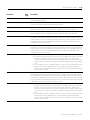
Index
Symbols
.ERR C-29
.SEGMENT C-30
.STATE C-30
.STATUS C-30
Numerics
1394C Drive module
Associated Axes Tab 7-10
New Axis button 7-11
Node X0 7-10
Node X1 7-10
Node X2 7-10
Node X3 7-11
Connection Tab 7-7
Inhibit Module checkbox 7-8
Major Fault on Controller if Connection Fails checkbox 7-9
Module Fault 7-9
Connection Request Error 7-9
Electronic Keying Mismatch 7-9
Module Configuration Invalid 7-9
Service Request Error 7-9
Requested packet Interval 7-7
General Tab 7-4
Base Node 7-5
Description 7-5
Electronic Keying 7-6
Compatible Module 7-6
Disable Keying 7-6
Exact Match 7-6
Name 7-5
Revision 7-5
Type 7-5
Vendor 7-5
Module Info tab 7-12
(16#xxxx) unknown 7-14
Configured 7-14
Internal State Status 7-14
Major/Minor Fault Status 7-13
Module Identity 7-15
Owned 7-14
Product Name 7-13
Refresh 7-15
Reset Module 7-15
Power Tab 7-11
Bus Regulator ID 7-11
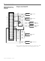
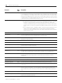
1394-CFLAExx Cable
Pinouts B-9
Wiring Diagram B-9
1394C-SJT05/10/22-D Digital Servo Drive Overview 7-3
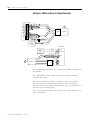
1398-CFLAExx
Cable Diagram B-7
Pinouts B-7
1756-M02AE Module Properties
Associated Axes Tab 3-12
Channel 0 3-13
Channel 1 3-13
New Axis button 3-13
Servo Update Period 3-13
Backplane Tab 3-17
ControlBus Parameters 3-17
ControlBus Status 3-17
Multicast CRC Error Threshold 3-18
Receive Error Counters 3-18
Refresh 3-18
Set Limit Button 3-18
Transmit Error Counters 3-18
Transmit Retry Limit 3-18
Connection Tab 3-9
Inhibit Module checkbox 3-10
Major Fault on Controller if Connection Fails checkbox 3-11
Module Fault 3-11
Requested Packet Interval 3-10
General Tab 3-8
Description 3-8
Electronic Keying 3-9
Name 3-8
Revision 3-9
Slot 3-8
Type 3-8
Vendor 3-8
Module Info Tab 3-13
Configured 3-15
Internal State Status 3-15
Major/Minor Fault Status 3-15
Module Identity 3-16
Owned 3-16
Refresh 3-16
Reset Module 3-16
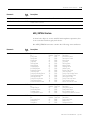
1756-M02AE servo module 1-1
Adding to a program 3-1, 6-1
Additional modules and axes 3-19
Block diagrams
Torque servo drive B-2
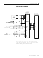
Velocity servo drive B-3
Publication 1756-UM006B-EN-P - July 2001