1
IQ
DATA PLUS II™
ww
w
.E
lec
tri
ca
lP
ar
tM
an
ua
ls
LINE METERING AND
PROTECTION SYSTEM
USER'S MANUAL
.c
om
TD 17271A
Effective September, 1989
@Westinghouse
ELECTRICAL COMPONENTS DIVISION
TD 17271A
.c
om
IQ DATA PLUS I I
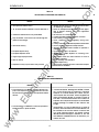
NOTE
an
ua
ls
All possible contingencies which may arise during installation, operation, or maintenance, and
all details and variations of this equipment do not purport to be covered by these instructions.
If further information is desired by purchaser regarding his particular installation, operation or
maintenance of his equipment, the local Westinghouse Electric Corporation representative should
be contacted.
ca
lP
ar
tM
Effective April, 1989
Copyright
Westinghouse Electric Corporation
Distribution and Control B usiness Unit
E lectrica l Components Division
Pittsburgh, PA 15220
ww
w
.E
lec
tri
©
First Printing:
September, 1989
TABLE OF CONTENTS
2
3
1 .0
1 .1
1 .2
1 .3
1 .4
Title
Sec/Par
Page
Introduction
Genera l . . . . . . . . . . . . . . . . . . . . . . . . . . . . . . . . . . . . . . . . . . . . . . . . . . . . . . . . . . .
Features a nd Options . . . . . . . . . . . . . . . . . . . . . . . . . . . . . . . . . . . . .
Required Externa l Ha rdwa re . . . . . . . . . . . . . . . . . . . . . . . . . .
Use of Ma nua l . . . . . . . . . . . . . . . . . . . . . . . . . . . . . . . . . . . . . . . . . . . . . . . .
Level of Repair . . . . . . . . . . . . . . . . . . . . . . . . . . . . . . . . . . . . . . . . . . . . . . .
Hardware Descripti on
7
4
5
5
5
5
2.0
Genera l . . . . .. . . . . . . . . . . . . . . . . . . . . . . . . . . . . . . . . . . . . . . . . . . . . . . . . . . . . . 7
2.1
Ha rdwa re Description . . . . . . . . . . . . . . . . . . . . . . . . . . . . . . . . . . . . . 7
2.1 . 1
Operator Pa nel . . . . . . . . . . . . . . . . . . . . . . . . . . . . . . . . . . . . . . . . . . . . 8
2. 1 .2
Rea r Access Area . . . . . . . . . . . . . . . . . . . . . . . . . . . . . . . . . . . . . . . 8
2 . 1 .2.1 SYNC Pulse . . . . . . . . . . . . . . . . . . . . . . . . . . . . . . . . . . . . . . . . . . . . . . . . 1 0
2 . 1 .2.2 Watthour Pulse . . . . . . . . . . . . . . . . . . . . . . . . . . . . . . . . . . . . . . . . . . . 1 0
2. 1 .3
Externa l Ha rdwa re . . . . . . . . . . . . . . . . . . . . . . . . . . . . . . . . . . . . . . 1 0
2.2
Specifications . . . . . . . . . . . . . . . . . . . . . . . . . . . . . . . . . . . . . . . . . . . . . . . . . 1 0
�
t
:n
Figure
1 .1
2.1A
2.1 B
�
.
......
.
.
........
...
.......
2.2
2.3A
2.3B
.....
...............................................................
5.0
5.1
Genera l . . . . . . . . . . . . . . . . . . . . . . . . . . . . . . . . . . . . . . . . . . . . . . . . . . . . . . . . . . . 29
Ba sic Block . . . . . . . .. . . . . . . . . . . . . . . . . . . . . . . . . . . . .. . . . . . . . . . . . . . . . 29
6.0
6.1
6.1 .1
6 . 1 .2
6 . 1 .3
6 . 1 .4
Genera l . . . . . . . . . . . . . . . . . . . . . . . . . . . . . . . . . . . . . . . . . . . . . . . . . . . . . . . . . . . 30
D I P Switch Settings . . . . . . . . . . . . . . . . . . . . . . . . . . . . . . . . . . . . . . . . 30
Current Tra nsformer Ratio . . . . . . . . . . . . . . . . . . . . . . . . . . 30
Display Current . . . . . . . . . . . . . . . . . . . . . . . . . . . . . . . . . . . . . . . . . . . 30
Line Frequency . . . . . . . . . . . . . . . . . . . . . . . . . . . . . . . . . . . . . . . . . . . 31
Overvolta ge, Undervoltage, Phase
Unba la nce - Insta nta neous or Delay . . . . 31
3 Wire/4 Wire Li ne . . . . . . . . . . . . . . . . . . . . . . . . . . . . . . . . . . . . . . 31
Overvoltage Detection Response . . . . . . . . . . . . . . . 32
U ndervolta ge Detection Response . . . . . . . . . . . . . 32
Phase Loss/Phase Reversa l
Detection Response . . . . . . . . . . . . . . . . . . . . . . . . . . . . . . . . 33
Phase Unba lance Detection Response . . . . . . 33
Potentia l Transformers' Ratio . . . . . . . . . . . . . . . . . . . . . 34
Pea k Dema nd Window a nd SYNC Pulse . . . 35
Protection Functions . . . . . . . . . . . . . . . . . . . . . . . . . . . . . . . . . . . 35
AC Line Voltage . . . . . . . . . . . . . . . . . . . . . . . . . . . . . . . . . . . . . . . . . . 35
Display Volts . . . . . . . . . . . . . . . . . . . . . . . . . . . . . . . . . . . . . . . . . . . . . . . 36
Norma l Operation . . . . . . . . . . . . . . . . . . . . . . . . . . . . . . . . . . . . . . . 36
Pulse Initiator Settings . . . . . . . . . . . . . . . . . . . . . . . . . . . . . . . . 36
% Line Overvolta ge Detection Level . . . . . . . . . . . 37
Alternate Power Fa ctor Ca lculation . . . . . . . . . . . . 37
Auto Reset . . . . . . . . . . . . . . . . . . . . . . . . . . . . . . . . . . . . . . . . . . . . . . . . . . 37
% Line U ndervoltage Detection Level . . . . . . . . . 37
% Phase Unba la nce Detection Level . . . . . . . . . 38
Walthour Count Reset . . . . . . . . . . . . . . . . . . . . . . . . . . . . . . . . 38
Protection Time Delay . . . . . . . . . . . . . . . . . . . . . . . . . . . . . . . . 38
Switch SW6 No. 8 . . . . . . . . . . . . . . . . . . . . . . . . . . . . . . . . . . . . . . . 38
Theory of Operati on
6 . 1 .5
6 . 1 .6
6 . 1 .7
6 . 1 .8
Application Considerati ons
ww
Title
Page
IQ Data Plus I I . . . . . . . . . . . . . . . . . . . . . . . . . . . . . . . . . . . . . . . . . . . . . . . . 4
Rea r Access Area . . . . . . . . . . . . . . . . . . . . . . . . . . . . . . . . . . . . . . . . . . . 7
Rear Access Area - Sepa rate Source
Power Module . . . . . . . . . . . . . . . . . . . . . . . . . . . . . . . . . . . . . . . . . . . . . 8
Dimensions . . . . . . . . . . . . . . . . . . . . . . . . . . . . . . . . . . . . . . . . . . . . . . . . . . . . . 9
Fusing for Three-Phase Power Module . . . . . . . . . . 1 0
Fusing for Sepa rate Source Power
Supply Module . . . . . . . . . . . . . . . . . . . . . . . . . . . . . . . . . . . . . . .. . . . . 1 0
Operator Pa nel . . . . .. . . . . . . . . . . . . . . . . . . . . . . . . . . . . . . . . . . . . . . . . 1 3
Power Quadra nts . . . . . . . . . . . . . . . . . . . . . . . . . . . . . . . . . . . . . . . . . . . 1 5
Induction Motor Load . . . . . . . . . . . . . . . . . . . . . . . . . . . . . . . . . . . . . . 15
Power Distribution . . . . . . . . . . . . . . . . . . . . . . . . . . . . . . . . . . . . . . . . . . 1 5
Chassis Cutout Dimensions . . . . . . . . . . . . . . . . . . . . . . . . . . . 17
Remova ble Power Module . . . . . . . . . . . . . . . . . . . . . . . . . . . . . 18
Remova ble Separate Source Power
Supply Module . . . . . . . . . . . . . . . . . . . . . . . . . . . . . . . . . . . . . . . . . . . . 1 9
Volta ge Selector Jumper . . . . . . . . . . . . . . . . . . . . . . . . . . . . . . . . 20
Wiring Diagra ms . . . . . . . . . . . . . . . . . . . . . . . . . . . . . . . . . . . . . . . . . . . . . 2 1
D I P Switches . . . . . . . . . . . .. . . . . . . . . . . . . . . . . . . . . . . . . . . . . . . . . . . . . . 27
Dl P Switch -Side View . . . . . . . . . . . . . . . . . . . . . . . . . . . . . . . . 28
IQ Data Plus I I Ba sic Block . . . . . . . . . . . . . . . . . . . . . . . . . . . . 29
LIST OF TABLES
Table
1 .A
1 .B
2.A
2.B
2.C
3.A
3.B
6 .A
6.B
6.C
6 .0
6.E
6.F
6 .G
6.H
6.1
6 .J
6.K
6.L
6.M
6 .N
6 .0
6 .P
6 .0
w
6 . 1 .9
6.1 .10
6.1.1 1
6.1 .12
6.1.13
6.1 .14
6.1 .15
6.1 .16
6 . 1 .17
6.1 .18
6.1.19
6 . 1 .20
6 . 1 .21
6 . 1 .22
6 . 1 .23
6 . 1 .24
General . . . . . . . . . . . . . . . . . . . . . . . . . . . . . . . . . . . . . . . . . . . . . . . . . . . . . . . . . . . 39
Troubleshooting . . . . . . . . . . . . . . . . . . . . . . . . . . . . . . . . . . . . . . . . . . . . . . 40
Initia l Startup . . . . . . . . . . . . . . . . . . . . . . . . . . . . . . . . . . . . . . . . . . . . . . . 40
Operational . . . . . . . . . . . . . . . . . . . . . . . . . . . . . . . . . . . . . . . . . . . . . .. . . 42
U nit Replacement . . . . . . . . . . . . . . . . . . . . . . . . . . . . . . . . . . . . . . . . . . . 42
tM
ar
Introduction . . . . . . . . . . . . . . . . . . . . . . . . . . . . . . . . . . . . . . . . . . . . . . . . . . . . . 17
Pa nel Prepa ration . . . . . . . . . . . . . . . . . . . . . . . . . . . . . . . . . . . . . . . . . . . 17
Cutout, Clearances . . . . . . . . . . . . . . . . . . . . . . . . . . . . . . . . . . . . . 17
Mounting . . . . . . . . . . . . . . . . . . . . . . . . . . . . . . . . . . . . . . . . . . . . . . . . . . . . . 17
Power Module . . . . . . . . . . . . . . . . . . . . . . . . . . . . . . . . . . . . . . . . . . . . . 18
yoltage Selector Jumper . . . . . . . . . . . . . . . . . . . . . . . . . . . . 18
Wm_ ng . . . . . . . . . . . . . . . . . . . . . . . . . . . . . . . . . . . . . . . . . . . . . . . . . . . . . . . . . . . . . 20
D I P Switch Settings . . . . . . . . . . . . . . . . . . . . . . . . . . . . . . . . . . . . . . . . 27
I nitia l Sta rtup . . . . . . . . . . . . . . . . . . . . . . . . . . . . . . . . . . . . . . . . . . . . . . . . . . 27
Before Power Application . . . . . . . . . . . . . . . . . . . . . . . . . . . 27
Initia l Power Application . . . . . . . . . . . . . . . . . . . . . . . . . . . . . . 28
lP
4.0
4.1
4. 1 . 1
4 . 1 .2
4. 1 .3
4. 1 .4
4.2
4.3
4 .4
4.4. 1
4.4.2
.E
lec
6
4.3
4.4
4.5
4.6
5.1
ca
5
Installation and Startup
3.1
3.2
3.3
3.4
4.1
4.2A
4.2B
tri
4
Page
LIST OF FIGURES
3.0
rr���gr ���- - . . . . .
. ...
.
13
3.1
Pushbuttons . . . . . . . . . . . . . . . . . . . . . . . . . . . . . . . . . . . . . . . . . . . . . . . . . . . 1 3
3.2
LEDs
13
3.2.1
Menu LEOs . . . . . . . . . . . . . . . . . . . . . . . . . . . . . . . . . . . . . . . . . . . . . . . . . 1 3
3.2. 1 . 1
Blinking LEOs . . . . . . . . . . . . . . . . . . . . . . . . . . . . . . . . . . . . . . . . . . . . . 1 5
3.2. 1 .2 Monitoring Inductive Loads . . . . . . . . . . . . . . . . . . . . . . . . . 15
3.2. 1 .3 Power Fa ctor Correction Ca pa citors . . . . . . . . . . . 15
3.2. 1 .4 Power Distribution . . . . . . . . . . . . . . . . . . . . . . . . . . . . . . . . . . . . . . . 15
3.2.2
U nit LEOs . . . . . . . . . . . . . . . . . . . . . . .. . . . . . . . . . . . . . . . . . . . . . . . . . . . . 15
3.2.3
Ala rm/Trip LEOs . . . . . . . . . . . . . . . . . . . . . . . . . . . . . . . . . . . . . . . . . 1 6
3.3
Display Window . . . . . . . . . . . . . . . . . . . . . . . . . . . . . . . . . . . . . . . . . . . . . . 16
3 .4
Walthour Counter . . . . . . . . . . . . . . . . . . . . . . . . . . . . . . . . . . . . . . . . . . . 16
3.5
Demand Watts . . . . . . . . . . . . . . . . . . . . . . . . . . . . . . . . . . . . . . . . . . . . . . . . 1 6
....
7.0
7. 1
7. 1 . 1
7. 1 .2
7.2
Title
Main tenance
an
1
ua
ls
Sec/Par
.c
om
TD 17271A
IQ DATA PLUS I I
6.R
6 .S
? .A
7.B
2
Title
Page
IQ Data Plus I I Features a nd Benefits . . . . . . . . . . . . 6
Communication Arra ngements . . . . . . . . . . . . . . . . . . .. . . . 6
Genera l Specifications . . . . . . . . . . . . . . . . . . . . . . . . . . . . . . . . . . . 1 1
Metering Sp ecifications . . . . . . . . . . . . . . . . . . . . . . . . . . . . . . . . . . 1 1
Protection Function Specifications . . . . . . . . . . . . . . . . . 1 2
Metered Va lues . . . . . . . . .. . . . . . . . . . . . . . . . . . . . . . . . . . . . . .. . . . . . . 14
Display Trip Conditions . . . . . . . . . . . . . . . . . . . . . . . . . . . . . . . . . . 1 6
I Q Data Plus I I Insta lla tion
Record Sheet: SW1 . . . . . . . . . . . . . . . . . . . . . . . . . . . . . . . . . . . . 30
CT Ratio Settings . . . . . . . . . . . . . . . . . . . . . . . . . . . . . . . . . . . . . . . . . . . 3 1
I Q Data Plus I I Installation
Record Sheet: SW2 . . . . . . . . . . . . . . . . . . . . . . . . . . . . . . . . . . . . 32
Overvoltage Detection Response . . . . . . . . . . . . . . . . . . . 32
U ndervoltage Detection Response . . . . . . . . . . . . . . . . . 32
Phase Loss/Reversa l Detection Response . . . . 33
Phase Unba la nce Detection Response . . . . . . . . . . 33
IQ Data Plus II Insta l la tion
Record Sheet: SW3 . . . . . . . . . . . . . . . . . . . . . . . . . . . . . . . . . . . . 34
PT Ratio Settings . . . . . . . . . . . . . . . . . . . . . . . . . . . . . . . . . . . . . . . . . . . 34
Peak Demand Sa mpling Interva l . . . . . . . . . . . . . . . . . . . . 35
IQ Data Plus I I Insta llation
Record Sheet: SW4 . . . . . . . . . . . . . . . . . . . . . . . . . . . . . . . . . . . . 35
AC Li ne Volta ge Selection . . . . . . . . . . . . . . . . . . . . . . . . . . . . . . 36
Watthour Pulse Settings . . . . . . . . . . . . . . . . . . . . . . . . . . . . . . . . . 36
IQ Data Plus I I Insta l la tion
Record Sheet: SW5 . . . . . . . . . . . . . . . . . . . . . . . . . . . . . . . . . . . . 37
Line Overvolta ge Detection (% Level) . . . . . . . . . . . . 37
Line U ndervoltage Detection (% Level) . . . . . . . . . . 37
IQ Data Plus I I Installation
Record Sheet: SW6 . . . . . . . . . . . . . . . . . . . . . . . . . . . . . . . . . . . . 38
Phase Unba lance Detection (% Level) . . . . . . . . . . . 38
Overvolta ge/U ndervolta ge/Phase U nba la nce
Time Dela y On Trip/Ara rm . . . . . . . . . . . . . . . . . . . . . . . . . . 38
Initia l Power-On Troubleshooting . . . . . . . . . . . . . . . . . . . 39
Operational Troubleshooting . . . . . . . . . . . . . . . . . . . . . . . . . . 41
IQ DATA PLUS I I
.c
om
TD 17271A
QUICK LIST FOR IQ DATA PLUS II INSTALLAT ION
It is suggested that you thoroughly fam i liarize yourself with
the IQ DATA PLUS II User's Manual before attem pting instal
lation. This list should be used to assist you.
ua
ls
5. If installing an IQ DATA PLUS II equipped with a 3-phase
power module, be sure that the voltage jumper is in the
correct position. Power up the unit. If the unit does not
power up or if one or more phases are reading the incorrect
voltage, check the fuses located just above the voltage
inputs inside the cover of the power module. The fuses
should sit comfortably in their clips. Possible problems are
blown fuses or fuses that have shaken loose in transit.
1 . The first thing to check on the IQ OATA PLUS II is that the
voltage selector jumper is shorting at the correct level.
Each product is shipped from the factory at 1 20 v olts.
tM
ar
3. Connect the power leads to the voltage inputs of the IQ
DATA PLUS I I-directly from the l ine if 600 volts or below,
from PT's for up to 1 4.4 kV. Be sure to take special care of
the phasing of the voltage. (The IQ OATA P LUS I I looks for
an A-B- C sequence.) The IQ DATA PLUS II is extremely
phase sensitive-errant readings could occur in the power
calculations if the phasing is wrong.
an
2. Using the technical manual, Sections 4.3 and 6, setthe D I P
switches o n the back of the IQ DATA PLUS I I at the desired
values (CT ratio, PT ratio, nominal line voltage, protection
settings) .
ca
lP
4. Connect CT inputs to the CT term inals of the IQ DATA
PLUS I I . Again be extremely careful to connect the inputs
correctly and to line up the phases with the voltage. (The
product could read voltage and current correctly, but read
watts, vars, PF, and watthours incorrectly if the CT inputs
are reversed or if the current phase does not match with the
voltage phase.)
6. If you think a problem exists, check the voltage and current
readings with hand-held meters. If they are correct, the unit
should be operating correctly. If an LED is not functioning,
return the device to the factory for repairs. If a fuse is burned
out, replace it with Buss Type KTK-R-3/4 or equivalent.
tri
IMPORTANT
lec
Areas in this manual shaded in gray (
) pertain only to
those units which operate with the optional 120/240 VAC
.E
Separate Source Power Supply Module (style number
2D78522G02). If your unit does not have this option, please
ww
w
skip these shaded areas.
Shaded area designates informati on that
replaces or supplements applicati ons using
the 1 20/240 VAC Separate S ource Power
Supply Module.
3
IQ DATA PLUS I I
.c
om
TD 17271A
Section 1
IN T RODUCTION
•
AC line cu rrent (each phase)
•
AC li ne to li ne voltage (all three)
•
AC li ne to neut ral voltage (fou r-wire syst ems- all t h ree)
•
W atts
•
Vars
•
Power Factor
•
Peak Demand
•
Watt- hours
Cu rrent monitori ng is throug h ex ternal cu rrent t ransformers
wit h ratios b et ween 1 00/5 to 5000/5.
an
Typical applicat ions for the IQ D ata Plus I I are:
•
Incoming 3-phase AC lines
•
Transformer feeder circuits
•
Branch ci rcuits
tM
F req uency
Voltag e may be di rectly monitored on 3-phase AC lines wit hi n
a range of 1 20 t o 600 VAC nomi nal without external potential
t ransformers and wit hi n a rang e above 600 VAC to 14.4KV
with ex ternal potent ial t ransformers.
•
Motor starters
•
3-phase electrical loads
A listing of the 15 monitored items a ppea rs on the u nit's
fa ceplate, as shown in Figu re 3.1 on page 12.
ar
•
ua
ls
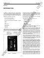
1.0 Genera l- The IQ Data P lus 11™ is a microprocessor
based, self-contained , door-mounted device desig ned to both
mrmitor and display electrical parameters as well as to pro
tect i ndust rial eq uipment connected to the li ne. (See Fig ure
1.1)
T he elect rical parameters it meters are:
The unit will auto-range all monitored values displayed on the
screen by means of a floating decimal point and U NITS, KILO,
and M EGA LED's on t he device's faceplate. See Fig u re 3. 1.
lP
It monitors the AC line feeding a specific load or loads to
detect conditions which exceed user-chosen electrical
parameters. It may protect the loads aga inst such conditions
as:
• U ndervolt age
• P hase Loss
• Overvoltag e
• P hase U nbalance
• P hase R eversal
ca
The prog ram di recti ng the monitoring function is permanently
stored in the IQ Data Plus I I, and so there iS no need to reload
prog rams after an AC power loss. Threshold set points, cho
sen by t he user, are also retai ned throug hout a power loss
by means of D IP switch setti ngs.
tri
T he non-volatile memory of the IQ Dat a Pl us I I will not only
maintain programmed setpoi nts , it will save a "snapshot" of
a ll metered val ues j ust b efo re a trip conditio n. These values
ca n be st epped throug h and recorded before resetting the
unit to aid in t roub leshooting the system .
lec
T he u n it's monitoring a nd protective fu nctions a re prepro
g rammed in the form of softwa re su pplied as sta nda rd a nd
resident in the IQ Data Plus II m icroprocessor. A com plete
listing of the monitored values is g iven in Table 3.A on pag e 1 3.
.E
T he Operator Pa nel, which makes u p the unit's front face, su p
ports a Display Window which visua lly indicates the a ctua l
va lu e of the metered item selected for display. The Display
Window is a lso u sed to visually indicate the cau se of a
detected trip sig nal. A self-diag nostic check prog ram a lso initi
ates a malfu nction display shou ld the IQ Data Plu s II detect
a n interna l ma lfu nction.
ww
w
T he u nit's prima ry fu nction is to monitor a nd display electri
ca l pa ram eters that a re requ ired or desired by a n operator.
Figure 1.1
-
T he u n it's secondary fu nction is to monitor a 3-phase AC line
and, if the tolera nces a re exceeded, a protective fu nction will
enable an interna l Ala rm a nd/or Trip Relay. Contacts from
these relays may be u sed to a lert personnel, to tu rn off the
IQ Da ta P lu s I I
4
TD 17271A
.c
om
IQ DATA PLUS I I
to carry o ut metering functions involving current. I n retrofit
cases where o nly 2 current transfo rmers are provided, see the
sample wiring diagrams in F igures 4.4C, 4.4D, 4.41 and 4.4J .
load device, or to do both.
In instances where a particular protective item is not necessary
for the applicatio n , it can be disabled, although it remains
passively resident sho uld it be required later.
NOTE: A 2 CT arrangement will wo rk, but wil l not detect a
current phase loss on L2 .
The IQ Data Plus II is available in two models. One style
(2 D78522G01) co mes equipped with a three-phase Vo ltage
Power Module. Power fo r this unit is derived from the line being
monitored. The seco nd style (2 D78522G02) is packaged with
a 120/240 VAC Separate So urce Power Supply Module. This
model of the IQ Data Plus II requires 120 or 240 VAC control
power.
The CT's may be chosen fro m a wide range of ratios, as is
indicated in Table 6.8 .
ua
ls
For appl icatio ns in which the mo nito red AC line is 600 VAC, o r
less, n o external potential transformers are required. I n
those cases where the monitored AC supply line exceeds 600
VAC, user-supplied potential transformers are required to step
down the vo ltage to match the maximum allowable vo ltage
permitted by the unit. See Tables 6.1 and 6.L fo r the vo ltage
ranges the IQ Data Plus II can monitor.
Since the IQ Data Plus II has o nly two models and very few
external optio ns, individualizing for an application is perfo rmed
in the field by the user/OEM. Users choose and enter the
specifications fo r the individual setpo ints by setti ng a series
of D I P switches. No specialized p rogramming language is
necessary.
an
1 .3 Use of Manual - This m anual is des igned for use during
instal lation and troubles hooting and, if necessary, unit
repl acem ent. It also has inform ation of s pecific importance
for the user's appl ication engineer who is planning the overal l
system and who is determining the s etpoint val ues for a
s pecific IQ Data Plus I I application.
1 .1 Features and Opti ons- A l ist of features and benefits is
•
tM
given in Table 1 .A (page 6) . Since the IQ Data Plus II is a
standardized package, there are very few external optio ns.
The options are:
The manual is bro ad enough in scope to fo rm the bas is of
new employee fam il iarization, refres her training sessions, and
o n-going m aintenance.
A 36-inch Extensio n Cable (style number 7871A40G02)
which allows removal of the Three Phase Power Module
or Separate So urce Power Supply Module fro m the chas
sis for separate mo unting
A Communicatio ns Module (PONI Card)
See IL 17158A
•
A 120/240 VAC Separate So urce Power Supply Module
(style number 2 D78508G01)
The IQ Data Plus I I is capable of carrying o n external data
exchanges with a co mputer by means of a Co mmunicatio n
Module. Electrical 9perating data supplied over a two-wire
com munication link will suppo rt plant energy management
systems. This module can be added at any time. A l ist of
co mmunications co nfigurations is given in Table 1 .8 (page 6) .
1 .4 Level of Repair
This manual is written with the
ass um ptio n that only unit-level troubles hooting will be
performed . If the cause of malfunction is traced to an IQ Data
P l us II, the u n it s ho u ld be replaced with a s pare. The
malfunctioning unit should then be returned to Westinghouse
fo r facto ry repairs .
tri
ca
lP
ar
•
It is stro ngly advised that the appl ication engineer carefully
read Sections 2 thru 6 befo re producing the appl ication's
wiring plan drawings and fil l ing out the Setpoint Record Sheet.
Installation teams should carefully read al l of Section 4 before
starting final instal latio n . Maintenance pers onnel s ho u ld be
famil iar with Section 7 before attempting to service the IQ Data
Plus II.
ww
w
.E
lec
1 .2 Required External Hardware- In all instances, it is rec
ommended that the IQ Data Plus I I use 3 user-supplied
external current transfo rmers, with 5 amp seco ndaries in o rder
5
-
T D 17271A
.c
om
IQ DATA PLUS I I
Table 1.A
IQ DATA PWS II FEATURES AND BENEFIT S
Benefit
Feature
•
•
All 15 va lues metered ava ila ble in each IQ Data Plus II
•
•
Undesired va l ues/functions may be disabled
•
•
Only two models - both monitor over a wide ra ng e of 3phase AC line voltag es
•
•
Nonvolatile memory
•
•
Simplified setpoint entry
Simplified Operator Pa nel
•
La rg e 6-dig it Display Window
•
Ea se of sta rtup
•
Sepa rate a ux ilia ry trip a nd a la rm relay contacts
•
•
•
•
•
tM
•
Reliable service without the need for numerous exter
na l measuring instruments
Allows for widesprea d standa rdization of units regard
less of specific metering a nd control a pplication
req uirements
No extra cost for unused features
In-field remova l/a ctivation of protection functions
Low inventory of spa res possible
Q uick, inex pensive i ntercha ngeability d u ring ma intena nce
In many cases eliminates externa l potentia l tra nsformers
No lost prog ra ms or specia l backup batteries
Setpoints a nd current va lues reta ined on trip/a la rm or
power loss
No specia l la ng uag e to be lea rned
No ela borate, complex keyboa rd or confusing , multi
function rea dings
Easy-to-read va lues a nd clea r indication of ca use of
trip/a la rm conditions
Q uick assembly a nd insta l lation
Simple setpoint entry
Allow control of externa l devices or loads when setpoint
thresholds a re exceeded
ua
ls
M icroprocessor-based control
an
•
•
•
ar
•
•
ca
lP
•
Table 1.B
tri
C OM M UNI CATI ON ARRANGEMENTS
Feature
•
A Loca l Area Network, Westing house INCOM, is formed
by 2 or more IQ Data Plus li s connecting to a persona l
computer via a sha red twisted pa ir of wires. T he per
sona l computer acts as a master. In this a rra ng ement the
PONI Communication Module is mounted on ea ch IQ
Data Plus I I . A CONI Communication Ca rd is used in a n
expa nsion slot of the persona l computer. A sta nda rdized
softwa re pa ckage is a vaila ble for data collection a nd
storag e.
Commu nications via RS232C to other microprocessor
based produ cts or phone modems.
•
Using INCOM, 2 or more IQ Data Plus lis (or other IQ
products), each with a PONI Communication Module, ca n
be connected to the two wire network to tra nsmit data
to a single Tra nsla tor Module. T his module converts
INCOM formatted messag es to RS232C for use with
other RS232C compatible devices. No softwa re is pro
vided in this ca se.
ww
w
•
Commu nication to an IB M PC ( or clone) persona l com
puter. This computer a cts as the master and ca n a lso
be u sed as the interface to other microprocessor-based
devices.
.E
lec
•
Benef it
6
TO 17271A
.c
om
IQ DATA PLUS I I
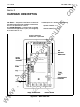
Section 2
HARDWARE DESCRIPTION
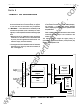
2 .0 General - T he pu rpose of this Section is to fam ilia riz e
the reader with the IQ Data Plus II ha rdwa re, its nomenclatu re,
a nd to list the specifications of the u nit.
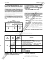
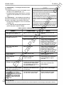
to be mou nted throug h a cutout in a pa nel. (T his will genera lly
be a ca binet's fa ce or doo r.)
•
Operator Pa nel ( Pa r. 2.1.1)
•
Rea r a ccess a rea ( Par. 2.1 . 2)
•
Externa l hardware ( Pa r. 2.1 .3)
H
2
A
H
1
8
H
2
8
H
1
C
H
2
C
lP
ar
H
1
A
tM
Current Transformer
Connections 3 phase AC
an
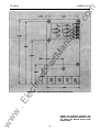
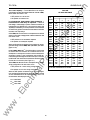
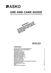
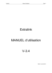
2.1 Hardware Description- The IQ Data Plus II is designed
ua
ls
T he description here is divided into the following :
lec
tri
Connection
ca
Power
Module ---!+--+
Field
Selectable
DIP Switches
Communication
Connection
ww
w
.E
WH
Pulse
Voltage Terminal Block
Neutral Terminal
Figure 2.1A - Rear Access Area
7
IQ DATA PLUS I I
tri
ca
lP
ar
tM
an
ua
ls
.c
om
T D 17271A
lec
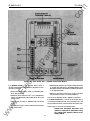
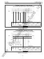
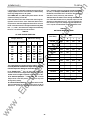
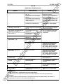
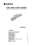
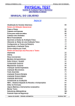
Figure 2.18
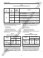
2.1.1 Operator Panel
-
Rear Access Area - Separate Source Power Module
T he Operator Pa nel, which is
norma lly a ccessible from the ou tside of the pa nel or door,
provides a m ea ns to:
•
.E
•
-
Monitor the a ctua l metered valu es
dow. (See Figure 3.1)
on
Determine the cause of a tr ip or a larm condition by mea ns
of a single-digit code shown in the Display Window. ( T he
descr iption of each code num ber is pr inted on the bottom
of the Operator Pa nel.)
•
Attem pt to r eset the u nit after a tr ip or a larm condition
has occurred by mea ns of a Reset pu shbutton
the Display Win
Determ ine which m eter ed valu e 1s oemg displayed by
mea ns of a n illum inated LED located at the left of the
m onitor menu
Step throu gh the menu of m eter ed items and a ctua l
va lu es
•
Determine that a tr ip or a larm condition ex ists by mea ns
of 2 distinct LEO s
T he u se of the Operator Pa nel is deta iled in S ection 3.
2.1.2 Rear Access Area- T he r ear of the IQ Data Plu s I I
i s norma lly accessible from the r ear of the pa nel's door. All
wir ing connections to the u nit are made at the chassis' r ear.
w
•
ww
•
Stu dy Figure 2.1 a nd note the following items:
8
Shaded area designates information that
replaces or supplements applications using
the 120/240 VAC Separate Source Power
Supply Module.
IQ DATA PLUS I I
1 . The 3-phase AC line connections connect to the Voltage
T erminal Block at the bottom of the IQ Data Plus I I .
2 . I f using a three-phase power module, the Voltage Selector
Jumper , essentially a shorting bar , must be positioned by
the user dur ing i nstallation to match 1 of 4 operating voltage
ranges. ( Installation procedur es, along with a listing of
r anges, are given in Par agraph 4 . 1 .4.) See Figure 2 . 1 A.
.c
om
TD 17271A
6. D I P switches, located o n the r ear r ight side of the chassis,
tailor each IQ Data Plus II to a specific application . These
D I P switches are set according to character istics such as:
• The exter nal PT and CT ratios
• The input voltage of the incoming AC l ine
•Whether to trip on overvoltage or undervoltage conditions
ua
ls
(A complete descr iption of each D I P switch setting is listed
in Section 6.)
7. The Power Module is factory-shipped mounted on the rear
of the IQ Data Plus I I chassis. However , this component
may be detached from the chassis and moved up to 36
inches (91 .44 e m) away if local codes prevent AC power
devices being located on the cabinet door .
Trip and alarm relays energize on device power-up and
de-energize on device power loss or trip condition. Ter
minal block label is in Trip/De-energized position. (These
9. A neutral Terminal is provided for 4-wire systems. (Wher e
the monitored A C lines are a 3-wire configur ation, this
ter m inal is not to be wir ed.)
ar
connections may be made at the NO or NC pairs (Form C)
associated with the internal Trip and Alar m Relays.)
an
5. Connections with controlled, exter nal devices, if used, are
made at the Tr ip/Alar m Ter minal Block.
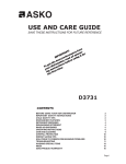
8. A fuse is located in ser ies with each of the 3 incoming AC
lines. The fuses are 3/4 Amp, 600 Volt, 200kA interr upting
r ating. These fuses are inter nal to the Power Module and
can be accessed by removing the three screws holding the
cover in place. (See Figures 2 . 1 and 2 .3.) If it is necessary
to replace fuses, make sure all voltage has been removed
from the IQ Data Plus I I before replacing the fuses.
tM
4. Connections from the 3 requir ed exter nal current trans
for mers are made at the Current Transfor mer Ter minal
Block located at the top of the chassis.
lP
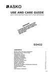
10. A Communication Port, located on the lower r ight of the
ca
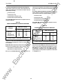
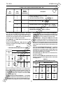
.______ 5.350----
0.500 __;
6.72
@
WESTINGHOUSE
10 DATA PLUS I I
o� 0""
I
Card (PONI)
4.420 ---
Without Card
o-·
0 ... o._.�
'------� 0 �" -·
.E
lec
Ip
i'
I
:-----,.
tri
Faceplate
With Communication
o·.·--
o•c·--
o•... �" .....
a�.. � -a"._
O•c• oa•ta•..
o·...
Q ..,.
t0.25
.0.''"""
.o·, ...
'OQ.'' ......
o·····
a .....,
0 .._., . .. .
a·, ......;: ... . ,
0 ··�<A-o· .
0""" .,_ •.
�
ww
w
·---
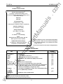
Figure 2.2 - Dimensions
9
Shaded area designates information that
replaces or supplements applications using
the 120/240 VAC Separate Source Power
Supply Module.
TD 17271A
.c
om
IQ DATA PLUS I I
2. 1.2.2 Watthour Pulse- The Wattho ur Pulse I nitiator is a
chassis, i s designed to connect with an optional Co m muni
cation Module (PONI Card).
Fo rm C contact that when activated will complete a circuit and
send a pulse signal to an exter nal pulse r ecorder . The length
between pulses is programmed using D I P switches. (See
Table 6.M.) The pulse duration is approximately 150 ms.
2. 1.3 External Hardware- Each 10 Data Plus II requires at
ua
ls
least 2 cur rent transfor mers be wir ed into the CT Ter minal
Block fro m an exter nal location. (See Figures 4.4A- 4.4L.)
These ar e user -supplied and must have a 5 amper e secondar y.
Potential Transfor mers are required when line voltage is above
600 volts. These are wired directly to the AC Line Connec
tion Ter minals. (See Figures 4.48 , 4.4D, 4.4F, 4.4 H , 4.4J, 4.4L.)
2.2 Speci fications - The following specificatio ns of the 10
Figure 2.3A- Fusing
For Three-Phase Power Module
Data Plus I I ar e co ntained here:
•
•
an
•
General specifications (Table 2.A)
Meter ing specifications (Table 2.8 )
Protection functio n specificatio ns (Table 2.C)
tM
Each of the protection functions can be individually D I P switch
selected to initiate either a trip, alar m , tr ip and alarm, o r nei
ther tr ip nor alar m condition . A sho rt description of each of
the protectio n functions follows:
Phase loss protection. A voltage phase loss is detected
when the amplitude of any single phase is less than 50%
of the nominal amplitude. A current phase loss is detected
when the current amplitude of the smallest phase is 1;;6
the current amplitude of the largest phase.
ca
lP
ar
•
Phase unbalance. A phase vo ltage unbalance is
detected when the difference of the largest and smallest
line to line vo ltages exceeds the percentage of nom inal
line voltage by a factor of 5, 1 0, 15, 20, 25, 30, 35, or 400/o.
(The % factor is deter m ined by DIP switches.)
•
Phase reversal. A phase r eversal is detected if a nega
•
Overvoltage. An overvoltage is detected when the ampli
tive voltage phase sequence is detected .
tri
2. 1.2. 1 SYNC PULSE - The SYNC PULSE input is essen
tially a sensor that r eceives a signal fro m a utility co mpany,
synchronizing the IQ Data Plus II with the demand window the
utility billing is ba sed o n . The SYNC PULSE is activated by
means of a D I P switch on the back of the IQ Data Plus I I . See
Table 6 . H , page 33. When the DIP switch for the SYNC
tude of the AC line voltage exceeds 1 05, 1 1 0, 1 15, 120,
125, 1 30, 1 35, or 140% of the no minal line voltage. (The
% factor is determined by DI P switches.)
.E
lec
•
PULSE is set, the demand time (5, 10, 15 or 30 minutes) is
overridden and the unit looks for a 24 volt DC signal to be
passed fro m Contact 1 and r eceived by Contact 2. When an
exterior co ntact is closed by the utility and the contact 1 -2
circuit is co mpleted, it ends the last demand per iod, updates
the displayed value, and begins the new period in line with the
utility. The IQ Data Plus II will keep its demand window
pr ecisely in line with the utility when this function is activated.
Undervoltage. An undervo ltage is detected when the
amplitude of the AC li ne voltage falls below 95, 90, 85,
80, 75, 70, 65, or 60% of the nomi nal line vo ltage. (The
% factor is deter m ined by D I P switches.)
All protection functions ar e updated every 1 .4 seco nds with
a 60 Hz line, or every 1 .5 seco nds with a 50 Hz line.
w
ww
•
Shaded area designates information that
replaces or supplements applications using
the 120/240 VAC Separate Source Power
Supply Module.
10
TD 17271A
.c
om
IQ DATA PLUS I I
Table 2.A
GENERAL SPECIFICATIONS
Device's Power Requirement<1>
PT Burden (3-Phase Power Module) 10 VA
PT Burden (Sep arate Source Power Module) 0.02 VA
C.T. Burden 0.003 VA
ua
ls
Frequency
5 0/60 Hz<2>
Line Characteristics
•
•
Nominal Line ± 20%
Will continue to op erate in event of a p hase loss
oo
an
Operating Temperature
to 70° C (32° to 158° F)
Storage Temperature
-20° to 85° C (-4° to 185° F)
tM
Humidity
0 to 95% R.H. noncondensing
ar
Fuses
(Supp lied with the unit) 3/4 amp ere, 600 volts
Buss Typ e KTK- R-3/4 (3 required)
Trip/Aiarm/WH Contact Ratings
lP
1 0 amp eres @ 120/240 VAC (Resisti ve)
1 0 amp eres @ 30 VDC (Resistive)
(1 ) For the I Q Data Plus I I with a Three Phase Power Module,
control p ower is drawn from the monitored incoming AC
Line Terminal connections. The minimum inp ut control
voltage is 90 VAC.
(2) D I P switch must be set for the correct incoming frequency.
ca
Table 2 . 8
METERING SPECIFICATIONS (1>
Accuracy
In % of Reading
Phase A, B, C
±10Jb
Line A-to-B, B-to-C, and C-to-A
±1 %
.E
lec
AC amperes(2> ( 3>
Voltage
Description
tri
Item
Voltage
Line A-to-neutral, 8-to-neutral, and C-to-neutral
±1%
Watts
Instantaneous watts collected and displayed each second
±2%
Vars
Power factor
Reactive power
W/VW2+Q2 for sinusoidal loads
±2%
Alt. power factor
W/(V h[3) for non-sinusoidal loads, and very light loads
±4%
Demand watts
Average watts occurring over a specified period. The period defined
by DIP switch settings can be 5, 10, 15 or 30 minutes. The DIP
switches can be disabled by using the Sync Pulse.
±2%
Frequency
Line frequency is displayed as a number and 2 decimal places (XX .XX).
This is updated every 1 0 seconds.
w
Watthours
Pulse initiator
±0.5%
±2%
Settable WH, KWH or MWH intervals
(1 ) Up dated every 1.4 seconds with a 60 Hz li ne or 1.5 seconds with a 50 Hz line, unless otherwise noted.
(2) At 2% of the CT ratio the unit will zero the current.
(3) Above 20% of the CT ratio the unit will meet accuracy.
ww
±4%
,
11
Table 2.C
PROTECTION FUNCTION SPECIFICATIONS<1l
Voltage Phase Loss
Current Phase Loss
ua
ls
Any p hase less than 50% of nominal
.c
om
TO 1 7271 A
IQ DATA PLUS I I
Smallest p hase less than 1/1s of largest p hase
Phase Unbalance<2l
Line voltage ± nominal
in ranges from 5 to 40%
an
Phase Reversal <3l
Absolute monitor ing
Overvoltage
Range
105 to 140%(2)
=
Range
tM
Undervoltage
=
95 to 60%(2)
Overvoltage/Undervoltage/Phase Unbalance/Delay
=
4
0 to 8 seconds< l
ar
Range
(1) All pr otection functions up dated approximately once p er
(3) See the descr iption of Paragrap h 2.2.
lP
second except current p hase loss which is up dated twice
p er second.
ww
w
.E
lec
tri
ca
(2) D I P switch selectable in 5% increments.
12
(4) D I P swi tch selectable in 1 -second increments. Note: the
tr ip delay setting is the same for all three protective func
tions: overvoltage, undervoltage, and p hase unbalance.
TD 17271 A
.c
om
IQ DATA PLUS I I
Section 3
OPERATOR PANEL
3.0 Introduction
This Section describes the op eration of
the 10 Data Plus I I . It is divided into the following Sections:
ua
ls
monitored item i s illuminated. At the same time the
current op erati ng value corresp onding to that item is
shown in the Disp lay Window.
-
•
Pushbutton (Par. 3.1 )
•
LEOs (Par. 3.2)
•
Di sp lay Wi ndow (Par. 3.3)
For examp le, whi le the Watts LED is illuminated, the Step
Disp lay, Down p ushbutton is p ressed once. Immediately
the LED next to VARS li ghts, and a new value is shown
in the Di sp lay Window.
3.1 Membrane Pushbuttons- The Op erator Panel supp orts
3 membrane p ushbuttons. (See Fi gure 3.1 . ) The membrane
pushbuttons p erform the following functi ons:
•
an
Table 3.A (page 1 4) contains a description of each of the
15 items that can be disp layed.
Reset. The Reset p ushbutton allows resetting from an
alarm or trip condition, assumi ng the cause of the
condition is corrected . (If the condition which caused the
alarm or trip is sti ll p resent, the alarm or trip occurs agai n
after the p ushbutton is p ressed.)
3.2 LE Os
The Op erator Panel LEO s are divided i nto 3
tM
•
If the Step Disp lay, Dow n p ushbutton is p ressed and held,
the 15 monitored items are continuously stepped through.
-
typ es:
3.2.1 Menu LE Os. At any given ti me, one of the LEOs
associ ated with a menu item is illumi nated . ( See Table 3.A
for a listing of these 1 5 items.) Each acts to identify which
menu item value i s currently being shown in the Disp lay
Wi ndow.
Step Display: Up/Down. The Step Di sp lay: Up/ Down
lP
ar
p ushbuttons are used to step through the 1 5 monitored
i tems li sted on the moni tor menu shown on the Op erator
Panel's face. Each time one of these p ushbuttons is
p ressed, the LED at the left of the newly selected
ca
(W )
WESTINGHOUSE
IQ DATA PLUS I I
•
ALARM
•
TRIP
lec
tri
Display Window
Menu LEOs.
__
__
__
One of these
ww
w
.E
is always lit.
RESET
•
•
___,.,.... .
__
•
•
•
•
•
•
•
•
•
•
•
•
•
•
lA
AMPS RMS
18 AMPS RMS
lc AMPS RMS
VA·B VOLTS RMS
V8.c VOLTS RMS
vC·A VOLTS RMS
VA·N VOLTS RMS
vB· N VOLTS RMS
vC·N VOLTS RMS
WATTS
VARS
POWER FACTOR
DEMAND WATTS
FREQUENCY
WATT- HOURS
Figure 3.1
•
Operator Panel
13
0
UNITS
KI LO-UN ITS
M EGA- U NITS
STEP
DISPLAY
UP
0
0
DOWN
1.
2.
3.
4.
5.
6.
7.
External Trip
Overvoltage
Undervoltage
Phase Unbalance
Phase Loss
Phase Reversal
Malfunction
10 DATA PLUS I I
.c
om
TD 17271A
Table 3.A
METERED VAWES
Display
Selection
Description
Format
or
v
XXXXXX
or
Phases A-to-8
v
XXXXXX
or
Phases 8-to-C
v
XXXXXX
or
Phases C-to- A
V A-N Volts RMS(1J
v
XXXXXX
or
Phase A-to-neutral
V B-N Volts RMS(1l
v
XXXXXX
or
V e-N Volts RMS(1J
v
XXXXXX
or
xxx.xxx
KV
xxx.xxx
KV
xxx.xxx
KV
xxx.xxx
KV
xxx.xxx
KV
Vars
Watthour Counter
XXXXXX
I nstantaneous Watts. Sampling time
1 second.
Menu LED blinks if this is a negative value. Refer to
Par. 3.2.2. Vars Menu LED blinks if the Vars are negative. Refer to Par. 3.2 .1 .1 .
Units in Watthours. Refer to Par. 3.4.
xxx.xxx
xxxxxx
xxx.xxx
XXXXXX
XXX .XXX
=
xxxx.xx
Power Factor. Menu LED blinks if the power factor is
lagging. Refer to Par. 3.2.1 .1.
xxxxxx
Demand Watts over a 5, 10, 15, or 30 minute interval
as determined by SW3 DIP switches 5 and 6 or by a
Sync Pulse Input (Contacts 1 & 2).
tri
KW
MW
lec
Frequency
Phase C-to-neutral
xx.xx
Power Factor
Demand Watts
Phase 8-to-neutral
ca
KW
MW
KV
MV
KWH
MWH
MWH
Watts
an
xxx.xxx
KV
tM
V c-A Volts RMS
ar
V e-c Volts RMS
xxx.xxx
lP
V A.e Volts RMS
Amps
K Amps
ua
ls
XXXXXX
lA Amps RMS
16 Amps RMS
lc Amps RMS
xxx.xxx
xx.xx
Incoming AC line frequency.
ww
w
.E
(1) These values are blanked automatically with systems which do not wire the neutral line to the Neutral Terminal of the IQ
Data Plus II. The blanking occurs when position 8 of SW1 is set for the 3 wire position.
14
TD 17271 A
.c
om
IQ DATA P LUS I I
3.2.1.2 Monitoring Inductive Loads - Typically when
monitoring induction motor loads the power flow is in Quad
rant 4. The watts are positive and the power factor is lagging.
VA RS
QUADRANT 2
QUADRANT 1
WATTS NEGATIVE
WATTS POSITIVE
I)
I)
LINE
VARS POSITIVE
POWER FACTOR LAGGING
POWER FACTOR LEADING
LINE
ua
ls
V A R S POSITIVE
EXAMPLE: C A PACI TIVE LOAD
BREAKER A
REVERSE POWER FLOW
N ORMAL POWER FLOW
X�
r
..:p
(�
-�---.-----+-- � X�
X+ I +
�X
-�
WATTS
WATTS N EGATIVE
WATTS POSITIVE
V A R S N EGATIVE
VARS NEGATIVE
an
EXAMPLE: INDUCTIVE LOAD
QUADRANT 3
BREAKER C
I
POWER FACTOR LAGGING
POWER FACTOR LEADING
BREAKER B
QUADRANT 4
MOTOR LOADS
Figure 3.2
ar
tM
MOTOR LOADS
Power Quadrants
lP
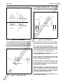
3.2.1.1 Blinking LEOs: Watts, Vars and/or Power Factor
tri
ca
To display reverse power flow, lagging (negative) power fac
tor, and negative var, the menu select LED being viewed will
blink. If it is not blinking the values are positive (leading). Refer
to Figures 3.2, 3.3, 3.4 for a further explanation.
lec
------� ffffl1
POWER FLOW
LINE
I
0
�
-
Condition 3: Breaker B & C closed, Breaker A open. The
power flow for Breaker B is in Quadrant 4 and the metering
condition is the same as condition 1 & 2. But the power flow
for Breaker C is reversed and will be in Quadrant 2. Only the
watts LED and power factor LED will blink .
w
ww
Power Factor Correction Capacitors
When
monitoring a load that also has power factor correction capa
citors and/or leading power factor synchronous motors such
that the net load is capacitive, then the power flow is in Quad
rant 1. In this case, none of the LEOs will blink.
3.2.1.3
Condition 2: Breaker A & C closed, Breaker B open. Power
flow for Breaker A & C is in Quadrant 4. The power factor and
var will be negative, and thus the LEOs will be blinking for
power factor and var readings.
LOAD
CURRENT T RANSFORMER
Figure 3.3
Thus by definition the power factor and var will be negative
and the LEOs will blink for these two values. Refer to Figure
3.3.
Condition 1: Breaker A & B closed, Breaker C open. Power
flow is in Quadrant 4. The power factor and var will be nega
tive and their respective LEOs will blink.
.E
I
Power Distribution
3.2.1.4 Power Distribution - Referring to Figure 3.4, three
conditions typically can be encountered.
-t----t--+---t----T-------j
-----
Figure 3.4
3.2.2 Units LEOs : Auto range units for monitoring -
kilo, mega. Refer to Figure 3.1.
Induction Motor Load
15
Units,
3.2.3 Alarm/Trip LEOs. The Alarm and Trip LEOs, when lit,
indicate that an alarm or trip condition ex ists, respectively.
At the same time a blinking digit, from 1 to 7, appears in the
Display Window. This digit represents the specific type of
alarm or trip condition that occu rred. { See Table 3.8.)
Table 3.8
3
U ndervoltage
4
Phase u nbal ance
5
Phase loss
6
Phase reversal
Phase unbalance
•
Malfunction
A trip or alarm condition
occurred as listed here.
See Tabl e 2 . C for a description of the trip specifications. Also Section 6
descri bes how to set the
DIP switches for the desired values.
ua
ls
•
An al arm only
•
A trip only
•
Both a trip and al arm
•
No trip or alarm
These reactions are selected by means of D I P switches
l ocated on the rear of the unit. { Section 6, Appl ication Con
siderations, l ists each D I P switch setting.)
an
Overvoltage
•
3.3 Display Window
The 6-digit LED Display Window dis
plays one of the 15 metered val ues listed in T abl e 3.A at any
given time. { See Paragraph 3.1 for details on sel ecting an
individu al value.) I n addition there are 2 special situations,
as listed next:
-
•
When a trip condition occurs, the Display Window con
tains a blinking digit from 1 to 7. Table 3. 8 lists each of
the conditions and suppl ies additional information where
needed.
•
An overrange occurs when a monitored value exceeds
the absolute range of the 6-digit Display, at which time
the val ue 999.999 appears on the Displ ay. For exam ple,
the instantaneous Watts val ue can display up to 9999.99
megawatts. If an instantaneous value of 10500.00
megawatts is monitored, an overrange condition would
ex ist, and the val ue freezes at its highest val ue, 9999.99.
ar
2
Indicates an internal malfu nction was m on itored
by the IQ Data Plu s II microprocessor. See Section 7, Maintenance, for
details.
Mal fu nction
ca
lP
7
Description
A trip initiated from a
remote device by m eans
of the Comm unication
Module.
External trip
Phase reversal
tM
1
•
The resulting overvoltage, undervoltage, phase u nbal ance,
phase loss, and phase reversal conditions can be individu ally
tailored to cause one of the following:
Display
Operator Panel
Designation
Phase loss
Table 3. 8 fu rther describes these conditions.
DISPLAY TRIP CONDITIONS
Window
Nu mber
•
.c
om
T D 17271A
IQ DATA PLUS I I
These digits may be compared with a listing of the conditions
on the bottom of the Operator Panel in order to identify the
cause of the alarm or trip condition.
3.4 Watthour Counter - To reset, set D I P switch SW6 No.
4 (Table 6.0), and hold down the reset pushbutton for 5
The possible cau ses of the alarm and trip conditions are:
3.5 Demand Watts - This
tri
When an alarm cond ition occu rs, the internal Alarm Relay
is de-energized. Li kewise, when a trip condition occu rs, the
internal T rip Relay is de-energized. { External NO/NC contact
pairs, brought out from these Relays, are available to the u ser.)
seconds while the Menu L ED is illuminated for Watthours. The
Watthou r cou nter will not reset on a power loss.
lec
parameter will collect and calcu
late the average Demand Watts over a preset time period (or
by the SYNC PULSE). The IQ Data Pl us II will store the highest
value until the u nit is reset. The reading can be reset by holding
down the reset pushbutton for 5 seconds while the Menu L ED
is illu minated for Demand Watts. The Dem and Watts will not
reset on a power loss.
External trip
•
U ndervoltage
•
Overvoltage
ww
w
.E
•
16
10 DATA P LUS I I
.c
om
TD 17271A
Section 4
INSTALLATION AND STARTUP
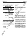
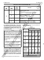
4.1.1 Cutout, Clearances- Since the IQ Data Plus II is typi
cally m ounted on a cabinet's door, it is necessary to prepare
a cutout in which it will be placed. The dimensions for this
cutout, along with the location of 6 mounting holes, are shown
in Figure 4.1. Before actually cutting the panel, be sure that
the req uired 3-dimensional clearances for the IQ Data Plus
II chassis allow mounting in the desired location. (Clearances
are shown in Figure 2.2.)
ua
ls
4.0 Introduction - This Section describes the following
•
Mounting (Par. 4.1)
•
Wiring (Par. 4.2)
•
D I P switch settings (Par. 4.3)
•
I n itial startup (Par. 4.4)
an
item s associated with the installation and startup of the IQ
Data Plus I I :
It is necessary to hold fairly close to tolerances when m ak
ing the cutout and placing the holes for the m ounting screws.
In particular the horizontal dimension between t he center of
the m ounting holes and the cutout's vertical edge m ust be
within 0 and +0.050 in. (0 . 13 em).
Earlier Sections, especially Section 2, Hardware Description,
should be read by anyone using this Section to install an IQ
Data Plus I I .
WARNING --------.
Do not high-pot or m egger this device.
4.1 .2 Mounting - Do not use a tap on the face since this
will remove excessive plastic from the holes, resulting in less
threaded m aterial to secure the IQ Data Plus II to its mount
ing panel.
lP
ar
4.1 Panel Preparation - This Paragraph describes the panel
preparation and mounting of the IQ Data Plus I I .
tM
,...---
ca
5.12
r
.201 DIA.
(6 HOLES)
..
/
.E
lec
tri
4.44
,I
4.44
w
ww
.13 -J
-
r-- 2.56 -
J_l
•
9.38
-
�
1
I--
I
I
5.38
I
J
1
�-
0
Figure 4.1 Chassis Cutout Dimensions
These dimensions m ust be -0 and + 0.050 i n .
17
IQ DATA PLUS I I
.c
om
TD 17271A
3.200
ua
ls
THREE PHASE PD�ER MODULE
STYLE NO.
1A49111H01
an
6.750
9966D75G01
lP
ar
tM
6.550
2.060
ca
1 . 600
C
�
NEU
3.60
-
Removable Power Module
Place the IQ Data Plus II through the cutout in the panel. Be
sure the Operator Panel faces outward. Use 0.5 in. (1 .2 e m)
long screws (included with the Data Plus II) to mount the unit
on a single-thickness panel. Be sure to start the screws from
inside the panel so that they go through the metal first.
.E
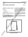
location desired. (See clearance dimensions i n Figure
4.2A or 4,213�
To separate the Power Module, remove the 2 mounting screws
securing it, then use the Module as a drilling template at the
new locati on. The two 8-32 screws can be used to remount
the Module in holes properly drilled and tapped.
4.1 .3 3-Phase Power Module and 1 20/240 VAC Separate
Source Power Supply Module - In those cases where it
w
4.1 .4 Voltage Selector Jumper - It is necessary to match
the placement of the Voltage Selector Jumper with the incom
ing AC line voltage, measured line-to-line. (See Figure 4.3.)
is necessary to remove the Power Module and mount it
separately from the chassis, be sure that:
•
The location allows for a cable connection between the
IQ Data Plus II chassis and Power Module by means of
the 36 in. (91.4 e m) Extension Cable Option.
•
The separated Power Module can physically fit in the
ww
�
B
1-ol<e----- Qf-------=>�l
tri
lec
Figure 4.2A
�
.,
',",
18
Shaded area designates information that
replaces or supplements applications using
the 1 20/240 VAC Separate Source Power
Su oolv Mod ul i'!.
TD 17271 A
lec
tri
ca
lP
ar
tM
an
ua
ls
.c
om
IQ DATA PLUS I I
-
Removable Separate Source Power Supply Module
ww
w
.E
Figure 4.28
Shaded area designates information that
replaces or supplements applications using
the 1 20/240 VAC Separate Source Power
Supply Module.
19
IQ DATA PLUS I I
.c
om
TD 17271A
Ribbon Cable
Connec tor t o
Power M odule
Voltag e
ua
ls
S el ector
Block
Power
an
Module
Figure 4.3 - Voltage Selector Jumper
1 . Phasing and pol arity of the AC cu rrent inputs and the
AC voltage inputs and their rel ationship is critical to the
correct operation of the wattmeter.
CAUT ION -------,
T he Voltage Selection Block on the Modu le accepts the
Voltage Selector Ju mper ONLY . Do not connect any other
type of wires to this T erminal Block since improper opera
tion and/ or equ ipment damage wi ll resu lt.
2. T he incoming AC line phases A, B and C wire directly
to the AC Line Connection Terminals on the chassis,
when l ine vol tage is 600 volts or less.
lP
ar
.------
A typical wiring plan is shown in Figu res 4.4A thru 4.4L.
Observe the Figu res and note the following:
tM
.---W
-- ARN ING
Never attempt to change the position of the Voltage Selec
tor Ju mper when AC l ine power is applied to the 10 Data
Plus II . Personal inju ry, i ncluding death, could result.
ca
A plastic cover with a screw is used to cover the Voltage
Selector Ju mper. T he Ju mper is positioned as determined by
the monitored, nominal AC line voltage. T here are 4 possible
po sitions, whic h represent ranges, measu red line-to-line. These
are:
=
460/ 575V
• 27 0 to 432 VAC
=
38014 1 6V
• 170 to 272 VAC
=
208/220/240V
• 96 to 1 54 VAC
=
1 20V
lec
These ranges are indicated on the Power Modul e, as shown in
Figu re 4.3. Consult the wiring plan drawings made up by the
user or OEM to determine the intended line voltage. Change
the Selector Ju mper to the Line Voltage when not using
potential transformers. When using potential transformers with
a 120 volt (or 1 1 0 volt) secondary, the Selector Ju m per shou ld
be positioned for 96- 1 54 volt range.
.E
6. T he protective fu nctions of the IQ Data Plus II directly
control the Trip or Alarm Relays, as described in Para
graph 2.2 and Table 2.C. DIP switch settings, l isted in
Paragr? ph 6.1 , determine if and when the Trip and Al arm
Relays wil l be energized .
7 . Sync Pu lse 24VDC on Terminal 1 .
8. W H Pu lse Initiator 10A 30VDC, 10A 120/240 VAC N O &
NC.
All wiring must conform to applicabl e Federal, state, and local
codes.
After repositioning the Ju mper, repl ace the plastic cover and
secu re with screw.
4.2 Wiring - T he wiring of the IQ Data Plus II must follow
a su itabl e "wiring pl an drawing." T h e term wiring pl an , as
u sed here, refers to the d rawings made for the specific appl i
cation. It describes all el ectrical connections between the IQ
Data Plu s II and the machine or process equ ipment. T his is
made u p by the u ser or OEM .
.-----
WARNING -------....,
Insu re that the incoming AC power and al l "foreign" power
sou rces are tu rned OFF and l ocked out before perform
ing any work on the 10 Data Plus II or its associated equ ip
ment. Failu re to observe this practice can result in seriou s
o r eve n fatal inju ry and/or equ ipment damage.
w
ww
4. T he wires connecting to the IQ Data Plu s II must not be
larger than AWG No. 14. Larger wires will not connect
properl y with the variou s terminal bl ocks.
5. Wiring between the cu rrent transformers and the IQ Data
Plu s II shou ld be kept as short as possibl e (200 feet
max .). Also, whenever possibl e, route these lines away
from other AC l ines and inductive devices. If the lines
must cross other AC lines, plan to cross them at right
angles.
tri
• 425 to 680 VAC
3. NO and NC contacts from the Al arm and Trip Relays can
be u sed to control external devices. T hese contacts are
rated at 10 amperes for 120/240 VAC or 30 VDC.
20
IQ DATA P LUS II
3
PHASE
3
WIRE (UP TO
600
.c
om
TD 17271 A
VOLTS)
D I R ECT VOLTAGE CONN ECTION & EXTERNAL C U RRENT TRANSFO R M E R S
:haL
B
L2
LINE
rn
�IY'\L
� L
A
L1
3CT
2CT
1 CT
LOAD
ua
ls
c
L3
an
1-1-
.
T T T
N EUTRAL
TER M .
Figure 4.4A
PHASE
3
-
PULSE
WH
r*T 1 r*T1 r*T 1
1 l
1
ALARM
3
2
4
5 6
7
8 9
10
11
Wiring Diagram
WIRE (ABOVE
lP
3
SYNCE TRIP
PULS
tM
:�
� ..
H1C H1B H1A
H2C H2B H2A
ar
FUS E
IQ Data Plus II
600
VOLTS)
EXTERNAL POTENTIAL TRANSFORM ERS & CU RRENT TRA N SFORMERS
B
L2
LINE
ca
c
L3
�
A
-�L
----L-3-v-,
� L
lec
FUSE
tri
L1
f""Y"1
rhl
1
.E
O P E N D E LTA
PT C O N N ECTION
�
ww
w
FUS
�
,D
=
·.
�
3CT
2CT
1 CT
LOAD
�
IQ Data Plus II
•
H1C H 1 B H1A
H2C H2B H2A
T T T
.\J E U TRAL
TERM.
Figure 4.48
-
SYNCE TRIP
PULS
l l
1
2
Wiring Diagram
21
ALARM
PULSE
WH
r*T 1 r*T 1 r*T 1
3
4
5 6
7
8 9
10
11
IQ DATA PLUS I I
3
PHASE
3
WIRE (UP TO
VOLTS)
600
2 CT's WIT H IQ DAT A PLUS II
.c
om
TD 17271A
D I R ECT VOLTAGE CONN ECTION & EXTERNAL C U R R E NT TRANSFO R M E R S
L2
2CT
. f""V"'\
1 CT
·,�.
A
L1
. rv-...
L
� L.
LOAD
ua
ls
LINE
C
B
L3
�"'\
cO
B
N E UTRAL
TE R M .
SYNCE TRIP ALARM WH E
1'ULS
H1C
H1B
H1
H2C H2B H2A l l IT 1 r*r 1 r9 1
10 11
i i i 12
tM
�
IQ Data Plus I I
•
Figure 4.4C
PHASE
3
-
4
5
6
7
8
9
Wiring Diagram
WIRE (ABOVE
lP
3
3
ar
�
FUS
I
an
-
600
2 CT'S WIT H IQ DATA PLUS I I
VOLTS)
EXTERNAL POTENTIAL TRANSFOR M ERS & C U R R E NT TRANSFO R M E R S
2
C
��
CT
l ________
·�
�
Y4L3 ----------��--------------*
ca
B
·,�.
-.11.
-.--
L
L2 ------�--�--+-
A
L1
LOAD
Q y [
WL
lec
FUSE
1 CT
tri
LINE
rN
.E
O P E N D E LTA
PT C O N N ECTION
��
l
ww
w
FUS
IQ Data Plus I I
.
N E UTRAL
TERM.
Figure 4.4D - Wiring Diagram
NOTE: This circuit will work, but will not detect a current phase loss if L2 is grounded.
22
TD 17271A
3
PHASE
4
WIRE (UP TO
VOLTS)
600
.c
om
IQ DATA P LUS I I
an
ua
ls
D I R ECT VOLTAGE CONNECTION & EXTERNAL C U R R E NT TRANSFO R M E R S
10 Data Plu s II
FUS
c
B
�;�T ���T ���T 1 1
tM
�o
SYNCE TRIP
PULS
1
2
ar
N E UTRAL
TERM.
ALARM
PULSE
WH
IT 1 r*r 1 IT 1
3
4
5 6
7
8 9
10
11
Figure 4.4E - Wiring Diagram
PHASE
4
WIRE (ABOVE
lP
3
600
VOLTS)
EXTERNAL POTENTIAL TRAN SFO R M E R S & C U R R E NT TRANSFO R M E R S
c
B
L2
LINE
A
�("Y"',_L.
N
3CT
2CT
1CT
LOAD
L.
�
tri
L1
rY"'.
",J,rY"'.L
ca
L3
lec
FUSE
.E
WYE
CONN ECTION
I
IQ Data Plus I I
PSYNCL TRIP
ww
w
FUSE
A
N E UTRAL
TERM.
ALARM
WH
�;�i ���T ���i t r IT 1 r*r 1 r*t 1
I
1
1
1
2
Figure 4.4F - Wiring Diagram
23
a
4
5 6
7
8 9
10
11
T D 17271A
3
PHASE
WIRE (UP TO
3
.c
om
IQ DATA PLUS I I
VOLTS)
600
D I R ECT VOLTAGE CONN ECTION & EXTE RNAL C U RRENT TRANSFO R M E R S
3CT
rY'"\
C
L3 ----------��------------���--�-----
�---�[
2CT
B
L2 ------�----�--------+---����-------
1 20/240 VAC
CONTROL POWER
TTTTT
;J
•
•
� FUSE
bJ
1
2e 3e 4
A
(SEE LABEL FOR
120/240 VAC JUMPERS)
B
c
Neu
I--
H1C H1B H1A
H2C H2B H2A
-
3
10
5 6
4
Data Plu s I I
600
VOLTS)
2
PULSE
WH
7
8 9
10
11
Wiring Diagram
WIRE (ABOVE
lP
3
ALARM
r*r 1 IT 1 IT 1
l l
1
ar
Figure 4.4G
PHASE
LOAD
SYNCE TRIP
PULS
i T i
SEPARATE SOURCE POWER SUPPLY MODULE
3
L
1CT
ua
ls
�rv'"\l
A
an
L1
tM
LINE
EXTERNAL POTENTIAL TRANSFO R M E R S & C U R R E N T TRA N S FO R M E R S
c
B
L2
L1
wl�
�I
o
O P E N D E LTA
PT C O N N ECTION
.E
120/240 VAC
CONTROL POWER
TTT T T
�
FUS
w
A
2e 3• 4
1
(SEE LABEL FOR
120/240 VAC JUM PERS)
;:J
�
H1C H 1 B H1A
H2C H2B H2A
1 CT
LOAD
T T i
SYNCE TRIP
PULS
l l
1
2
Figure 4.4H
-
Wiring Diagram
24
ALARM
PULSE
WH
r*r 1 IT 1 IT 1
3
10
SEPARATE SOURCE POWER SUPPLY MODULE
ww
2CT
Q
----- --
cO "':
3CT
L
lec
FUSE
A
tri
LINE
rY'"\
'�L
r-?{V)T:
ca
L3
4
5 6
Data Plus I I
7
8 9
10
11
3
PHASE
WIRE (UP TO
3
600
VOLTS)
2 CT's WITH IQ DATA PLUS I I
DI R ECT VOLTAGE CONN ECTION & EXTERNAL C U R R E NT TRANSFO R M E R S
C
2CT
. r-Y:"1
8
L
J.
3:
VAC
POWER
T T T T T
1 2e 3e
120/240
A
4
�
•
�
FUS
c
(SEE LABEL FOR
VAC J U M PERS)
Neu
-
�
ar
Figure 4.41
3
-
4
5
WH
6
10 Data Plus I I
7
8
9
Wiring Diagram
WIRE (ABOVE
lP
PHASE
,b
SYNC TRIP ALARM
E
�;i� ���T �;{rr
IT 1 r*r1 r9
10 111
i 12 3
L
SEPARATE SOURCE POWER SU PPLY MODULE
3
L
tM
120/240
LOAD
an
�\
cONTROL
1 CT
.r'C'J.
A
L
L
ua
ls
L3
2
1
LINE
.c
om
IQ DATA PLUS I I
TO 17271 A
600
2 CT'S WITH IQ DATA PLUS II
VOLTS)
EXTERNAL POTENTIAL TRANSFOR M E RS & C U R RENT TRANSFO R M E R S
ca
8
2
c
L ------�--+--�-
LINE
A
lec
FUSE
LOAD
tri
L1
O P E N D E LTA
PT C O N N ECTI ON
120/240
.E
VAC
CONTROL POWER
1 2e 3e
120/240
4
SYNC
TRIP ALARM PULSE
ULSE
�
H1C
H18
H1
H2C H28 H2A l l IT 1 r*r1 r*T 1
12 3 4
10 11
WH
A
w
(SEE LABEL FOR
VAC JUMPERS)
5
IQ Data Plus I I
ww
SEPARATE SOURCE POWER SUPPLY MODULE
Figure 4.4J
6
-
Wiring Diagram
25
7
8
9
T O 17271A
3
PHASE
WIRE (UP TO
4
.c
om
IQ DATA PLUS I I
VOLTS)
600
D I R ECT VO LTAGE CONN ECTION & EXTERNAL C U R R ENT TRANSFORM E R S
3CT
�(V"\-
2CT
.l.
8
�rv-'\L
;J L
A
L1
L
N
1 CT
LOAD
ua
ls
L2
LINE
fV"\
c
L3
an
�
120/240 VAC
CONTROL POWER
FUSE
8
c
A
1
2e 3e 4
(SEE LABEL FOR
1 20/240 VAC J U M PERS)
Neu
O
I--
SYNCE TRIP
PULS
tM
TYYTY
H1C H 1 B H1A
H2C H28 H2A
T T T
PULSE
WH
IT 1 r*r 1 IT 1
1 1
1
ALARM
3
2
4
5 6
7
8 9
10
11
IQ Data Plus I I
ar
SEPARATE SOURCE POWER SUPPLY MODULE
Figure 4.4K - Wiring Diagram
PHASE
WIRE (ABOVE
4
lP
3
600
VOLTS)
EXTERNAL POTENTIAL TRANSFO R M ERS & C U R RENT TRAN S FOR M E R S
ca
c
L3
8
L2
LINE
A
N
Lu..J Lu_J luA.
r'1 rrnl (Yll
WYE
C O N N ECTION
1 20/240 VAC
CONTROL POWER
.E
YYYTI
1
2. 3. 4
A
o
w
�o
FUS
(SEE LABEL FOR
1 20/240 VAC J U M PERS)
2CT
1 CT
LOAD
c
Neu
ll
-b
b
I--
SEPARATE SOURCE POWER SUPPLY MODULE
ww
-�i--v-\L
�
lec
FUSE
3CT
�rv-'\L
� L
tri
L1
fV"\
H1C H 1 B H1A
H2C H2B H2A
T i T
l
SYNCE TRIP
PULS
l 1
1
2
Figure 4.4L - Wiring Diagram
26
ALARM
PULSE
WH
IT 1 r*r 1 IT 1
3
4
5 6
IQ Data Plus I I
7
8 9
10
11
TD 17271A
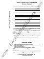
4.3 DIP Switch Settings - The D I P switches located and
accessed from the rear-right portion of the chassis must be
properly set according to application requirements. Obtain the
Installation Record Sheet produced specifically for the appli
cation. A blank Record Sheet is shown in the Tables 6.A, 6.C,
6. H , 6.K, 6. N, 6.0. Note: Section 6 describes how to deter
mine the D I P switch positions. Each of the DIP switches
SW1 thru SW6 - contains eight 2-position switches which
are set in combination. (See Figure 4.5.) The switches are
turned ON or OFF by sliding the switch. As you face the D I P
switches, slide:
To the LEFT to turn the switch OFF
•
To the RIGHT to turn the switch ON
OFF - ON
Current transformers' ratio
50/Pro6te0ction:selnoectdelionay/delay
wire/4 wire system
SW1
Hz
3
Figure 4.6 shows a side view of a single slide switch and how
it is turned on and off.
ua
ls
•
.c
om
IQ DATA PLUS II
SW2
an
Observe the ON and OFF designations on the DIP switches
shown in Figure 4.5. Always look for the OFF and ON desig
nations on the hardware or printed circuit board to be sure
you are setting the switches correctly.
tM
After all the D I P switches are set according to the settings
listed on the Installation Record Sheet, the system is ready
to have AC power applied. Follow the procedure listed in Para
graph 4.4 when first applying power to the IQ Data Plus I I .
SW3
lP
ar
4.4 Initial Startup - The information here i s intended to be
used when first applying AC power to the IQ Data Plus II. Each
item is shown with a box to the left. In this way it can be used
as a checklist to reduce the chance of omitting or skipping
an item.
SW4
tri
ca
.------ WARNING --------,
The following startup procedures m ust be performed only
by qualified personnel who are familiar with the IQ Data
Plus II and its associated electrical and/or mechanical
equipment. Failure to observe this caution can result in
serious or even fatal personal injury and/or equipment
damage.
Detected overvoltage response
Detected undervoltage response
Detected phase loss/reversal response
Detected phase unbalance response
Potential transformers' ratio
Peak demand window (minutes)
(ON/ioOnsFF)(ON/OFF)
PrSyncotectPulionseFunct
Nominal AC line voltage setting
Test·factory use only
Pulse initiator settings
Line overvoltage detection level
e PowerResetFactor Calculation
AutAlteor/nMatanual
Line undervoltage detection level
%
4.4.1 Before Power Application
Before applying AC
power to the IQ Data Plus II, perform the following :
-
lec
SW5
O Verify that the incoming AC power to the system is discon
nected. Also, if foreign power sources - such as may be wired
to the Alarm and Trip Relay contacts- are wired into the panel,
verify that these sources are turned OFF and, if possible,
locked out.
.E
%
D Verify all DIP switches are set according to the Installation
Record Sheet.
Phase unbalance detection level
count reset
Protection interval time setting
Unused
%
o If installing an IQ Data Plus I I with a 3-Phase Power Module,
verify that the position of the Voltage Selector Jumper on the
Voltage Terminal Block is correct for the nominal voltage.
SW6
w
O Verify that all wiring is correct, as shown on the wiring plan
drawings.
WH
o
ww
When possible, disable the IQ Data Plus I I until the rest of the
machine or process has been started up and checked out.
Figure 4.5 - DIP Switches - See Section 6
for programming information
27
TD 17271A
D
_
_
_
D
___
OFF
ua
ls
ON
.c
om
IQ DATA PLUS I I
o
Remove the 3 line fuses contained in the Power Module of
the IQ Data Plus II.
Figure 4.6
-
DIP Switch (side view)
o
Turn on AC power and verify that the line-to-line voltages (A
to-B. A-to-C, and 8-to-C) fall within the correct range, as noted
on the wiring plan drawing. Note: The voltage range must
match the Voltage Selector Jumper's position. See Paragraph
4. 1 .4 which lists the ranges.
The l A AMPS RMS LED illuminates
•
The Display Window shows the actual line phase A
amperes
4.4.2 Initial Power Application
Perform the following
steps when first applying AC power to the IQ Data Plus I I :
o
Remove AC power and re-install the 3 line fuses.
ar
-
If the voltages do not match - as determined by comparing
the actual reading with the Voltage Selector Jumper's position,
refer to the system wiring drawings to locate the error.
tM
•
an
D Restore AC power and verify that the Operator Panel func
tions, after an initial 2-second delay, are as follows:
ww
w
.E
lec
tri
ca
lP
�----- NOTE --------�
If a trip or alarm occurs, refer to Section 7, Maintenance,
for details.
Shaded area designates information that
replaces or supplements applications using
the 120/240 VAC Separate Source Power
Supply Module.
28
IQ DATA PLUS I I
.c
om
TO 17271A
Section 5
T HEORY O F OPERAT ION
- This Section provides a general description
of how the IQ Data Plus II functions internally. Its purpose
is to give the user only an overview theory of operation.
•
Updating the Operator Panel o n a regular basis. When
a component of the Panel - such as the Step Display
Up pushbutton - is pressed, the executive program
reacts by displaying the new information requested in the
Display Wi ndow.
•
Conditioning the signals from the control area to make
them compatible with the Operator Panel devices and the
internal Trip and Alarm Relays. This is carried out in the
interface area.
5.1 Basic Block- The IQ Data Plus II is controlled by a self
tM
The executive program assigns the highest priority to
energizing the Trip and Alarm Relays. Lower priorities are
given to other operations, such as updating the Display
Window of the Operator Panel.
Checking the information obtained from the AC line being
monitored for the various trip and alarm conditions, as
listed in Paragraph 2.2.
ca
lP
ar
•
an
contained microprocessor which is directed by an "execu
tive program" resident in ROM (read-only memory). (See
Figure 5.1.) The m icroprocessor directs the following 4 oper
ations:
• Monitoring the AC line voltage and currents and storing
their levels in a "data table" which is a solid state mem
ory device. (The actual signals from the AC line are "con
ditioned" by various circuits grouped together here and
referred to simply as the line interface).
ua
ls
5.0 General
;--
II:
II:
....
...
...
II:
.E
AC line
current
I
I
tri
...
i
n
t
e
r
f
a
c
e
I ..
lec
AC line
voltage
L
i
n
e
.---
M icroprocessor
Executive
program
I
I
I
I
Data
table
I
n
t
e
..
Operator
Panel
Components
I--f--
r
f
a
c
e
...._
ro..
...
�
...
�
�
'----
Alarm
Trip
and
WH
Pulse
Relays
SYNC
PULSE
w
ww
..
Figure 5.1
-
IQ Data Plus I I Basic Block
29
T D 17271 A
.c
om
IQ DATA PLUS I I
Section 6
APPLICATION CONSIDERATIONS
6.0 General - This Section contains various considerations
to be kept in mind when applying the IQ Data Pl us II to a
specific application. It is designed primarily for the systems
or application engineer responsible for making up the wiring
plan drawings.
It is strongly suggested that all earlier Sections - especially
2 and 3 - be read thoroughly before proceeding.
Table 6.A
an
ua
ls
6.1 DIP Switch Settings - A number of DIP switches,
located on the right rear side of the chassis, tailor each IQ
Data Plus II to a specific application The switches provide 18
selection groupings which must be set by the user during
installation. Once these settings are determined, they should
be recorded on a copy of the Installation Record Sheet, shown
in Tables 6.A, 6.C, 6.H, 6.K, 6.N, 6.0. The filled-in Record Sheet
should then be made available to the installation team and
to maintenance personnel. Paragraph 4.3 describes how to
physically set the switches.
Switch
1
2
3
4
5
-
The ratio of the external current transformers
:5
(1 00/150/200/250/300/400/500/600/800/1000/1200/1500/1600/
Refer to Table 6. 8
2000/2500/3000/3200/4000/5000)
=
__
ca
-
-
lec
8
-
Line frequency ON
=
60 Hz; OFF
=
50 Hz
Action on over/undervoltage/phase unbalance detection.
Action
i mmed. (Delay/immediate)
OFF
i mmediate; ON
delay
=
=
=
AC line wiring
3 wire
3 wire or 4 wire
=
6.1 .1 Current Transformer Ratio
The ratio of the user
provided external current transformers can vary from 100:5
to 5000:5. Switch SW1 , Nos. 1 thru 5 must be set to cor
respond to the external current transformer's ratio, as listed
in Table 6.8.
ON
OFF
6.1 .2 Display Current
=
=
4 wire
3 wire
The AC line current level appear
ing in the Display Window is auto ranged to represent
amperes to kiloamperes.
.E
-
The CT's must be chosen so that at least 20% of the pri
mary rated current is drawn. The 1 % accuracy of the IQ
w
Data Plus II is valid only above 20% of the current rating.
Below 2% of the primary rated current, the IQ Data Plus
II reads zero current.
ww
Description
lP
-
6
7
Combinations
tri
SW1
Setting
ON/OFF
Slide
Switch
ar
DIP
tM
IQ DATA PLUS II INSTALLATION RECORD SHEET: SW1
30
-
6.1.3 Line Frequency - The IQ Data Plus II can accept a
line frequency of either 50 or 60 Hz. Selection is made at SW1 ,
No. 6. Place the switch in the:
OFF position for a 50 Hz line
•
ON position for a 60 Hz line
Table 6.8
CT RATIO SETTINGS
CT
Ratios
6.1.4 Overvoltage, Undervoltage, Phase Unbalance Instantaneous or Time Delay on Trip/Alarm - When an
overvoltage, undervoltage or phase unbalance condition is
first detected, the IQ Data Plus II can actuate its Alarm and
Trip Relays immediately; or the trip condition can be selected
to continuously persist for several seconds before it actuates
the Alarm and Trip Relays.
•
OFF position for an immediate response
•
ON position for a delayed response
3
4
5
ON
ON
ON
ON
ON
ON
ON
ON
ON
OFF
ON
ON
ON
OFF
OFF
ON
ON
ON
ON
ON
ON
ON
OFF
ON
OFF
OFF
ON
OFF
OFF
ON
ON
ON
OFF
ON
ON
ON
1000:5
1200:5
1500:5
OFF
ON
OFF
ON
OFF
OFF
ON
ON
ON
OFF
OFF
OFF
ON
ON
ON
1600:5
2000:5
2500:5
ON
OFF
ON
ON
ON
OFF
OFF
OFF
OFF
OFF
OFF
OFF
ON
ON
ON
3000:5
3200:5
4000:5
5000:5
OFF
ON
OFF
ON
OFF
ON
ON
OFF
OFF
ON
ON
ON
OFF
ON
ON
ON
ON
OFF
OFF
OFF
1
2
100:5
150:5
200:5
ON
OFF
ON
ON
ON
OFF
250:5
300:5
400:5
OFF
ON
OFF
500:5
600:5
800:5
an
Switch SW1 , No. 7 m ust be set to correspond to the desired
action on over/under voltage/phase unbalance detection. Set
this switch to the:
SW1 Switch Settings(1l
ua
ls
•
tM
When the ON position is selected, the time delay can be pro
grammed using switches SW6, Nos. 5, 6 and 7. (See Para
graph 6.1 .23.)
lP
ar
6.1.5 3 Wlre/4 Wire Line - The IQ Data Plus II can be used
to monitor either a 3-conductor or 4-conductor AC line. An
example of a 4-wire system is a case in which a transformer's
secondary is wired in a wye configuration with the XO neu
tral terminal ground brought out as the fourth wire. In this case
the XO fourth wire connects with the Neutral Terminal on the
IQ Data Plus ll's chassis. (See Figure 2.1.)
Switch SW1 , No. 8 must be set to correspond to the chosen
wiring configuration. Set this switch to the:
OFF position for a 3-wire wiring configuration
•
ON position for a 4-wire wiring configuration
ca
•
VA-N Volts RMS
VB·N Volts RMS
•
VC·N Volts RMS
ww
w
.E
lec
•
tri
When the OFF position is selected for the 3-wire configura
tion, the Display Window does not display the 3 1ine-to-neutral
AC line measurements of the Operator Panel's menu. The
measurements not displayed are:
•
.c
om
IQ DATA PLUS II
TD 17271A
31
(1) All other combinations are invalid.
T D 17271 A
.c
om
IQ DATA PLUS I I
Table 6.C
IQ DATA PLUS II INSTALLATION RECORD SHEET: SW2
DIP
Slide
Setting
ON/OFF
Switch
Switch
Combinations
Action on overvoltage
(Do nothing/trip/alarm/trip and alarm) Refer to Table 6. D
-
=
-
3
4
Action on undervoltage
(Do nothing/trip/alarm/trip and alarm) Refer to Table 6. E
-
=
-
5
6
Action on phase unbalance
(Do nothing/trip/alarm/trip and alarm) Refer to Table 6.G
-
=
-
6.1 .7 Undervoltage Detection Response
Activate alarm relay
•
Activate both trip and alarm relays
•
Activate neither trip and alarm relays
Should an
undervoltage condition be detected, the IQ Data Plus II can
control the internal Trip and Alarm Relays in 4 ways:
lP
•
__
•
Activate trip relay
-
ar
-
Activate trip relay
__
an
=
-
6.1 .6 Overvoltage Detection Response
Should an over
voltage condition be detected, the IQ Data Plus II can control
the internal Trip and Alarm Relays in 4 ways:
•
__
Action on phase loss/reversal
(Do nothing/trip/alarm/trip and alarm) Refer to Table 6. F
-
7
8
__
tM
SW2
ua
ls
1
2
Description
ca
Switch SW2, Nos. 1 and 2 determine the response of the unit,
as listed in Table 6.D.
•
Activate alarm relay
•
Activate both trip and alarm relays
•
Activate neither trip and alarm relays
Switch SW2, Nos. 3 and 4 determine the response of the unit,
as listed in Table 6. E.
Table 6.E
OVERVOLTAGE DETECTION RESPONSE
UNDERVOLTAGE DETECTION RESPONSE
SW2 Switch Settings
1
lec
Response
of Relay(s)
tri
Table 6.D
ON
OFF
OFF
ON
2
Alarm only
Trip only
Alarm and trip(1l
No alarm or trip
OFF
ON
OFF
ON
.E
Alarm only
Trip only
Alarm and trip(1 >
No alarm or trip
Response
of Relay(s)
SW2 Switch Settings
3
4
ON
OFF
OFF
ON
OFF
ON
OFF
ON
(1) Relays energize or de-energize simultaneously
Note also that the Switch SW1 , No. 7 determines whether the
response is instantaneous or a selectable time interval, as
described in Paragraph 6.1.4. Switch SW6, Nos. 5, 6, 7 deter
mine the time interval, in seconds, as described in Paragraph
6.1 . 23. Switch SW3, No. 8 disables or enables all of the over
voltage and undervoltage protective capabilities, as described
in Paragraph 6.1 .12.
Note also that Switch SW1 , No. 7 determines whether or not
there is a time interval, as described in Paragraph 6.1.4. Switch
SW6, Nos. 5, 6, 7 determine the time interval, in seconds,
as described in Paragraph 6.1 .23. Switch SW3, No. 8 disa
bles or enables all of the overvoltage and undervoltage pro
tective capabilities, as described in Paragraph 6.1 .12.
ww
w
(1) Relays energize or de-energize simultaneously
32
IQ DATA PLUS I I
6.1 .8 Phase Loss/Phase Reversal Detection Response -
.c
om
TD 17271A
specific time i n seconds that the condition must persist before
the Alarm/Trip Relays are actuated as described in Paragraph
6.1 .23.
Should either a phase loss or phase reversal condition be de
tected, the IQ Data Plus II can control the internal Trip and
Alarm Relays in 4 ways:
6.1 .9 Phase Unbalance Detection Response - Should a
phase unbalance condition be detected, the IQ Data Plus I I
can control the internal Trip and Alarm Relays i n 4 ways:
Activate trip relay
•
Activate alarm relay
•
Activate both trip and alarm relay
• Activate neither trip and alarm relay
Switch SW2, Nos. 5 and 6 determine the response of the unit,
as listed in Table 6.F.
•
Activate trip relay
•
Activate alarm relay
•
Activate both trip and alarm relay
•
Activate neither trip and alarm relay
ua
ls
•
Switch SW2, Nos. 7 and 8 determine the response of the unit,
as listed in Table 6.G.
Table 6. F
PHASE LOSS/REVERSAL DETECTION RESPONSE
an
Table 6.G
SW2 Switch Settings
6
ON
OFF
OFF
ON
OFF
ON
OFF
ON
Response
of Relay(s)
Alarm only
Trip only
Alarm and trip(1)
No alarm or trip
ar
Alarm only
Trip only
Alarm and trip(1)
No alarm or trip
5
PHASE UNBALANCE DETECTION RESPONSE
tM
Response
of Relay(s)
(1 ) Relays energize or de-energize simultaneously
lP
There are no time interval enable/disable switch settings as described in Paragraphs 6.1.4 and 6.1 .23, respectively
for this feature.
Switch SW1 , No. 7 determines whether the Alarm/Trip Relays
ca
actuate on an immediate basis or after a delay.
•
OFF position for immediate actuation
•
ON position for delayed actuation
ww
w
.E
lec
tri
Note also that Switch SW6, Nos. 5, 6, 7, determine the
33
SW2 Switch Settings
7
8
ON
OFF
OFF
ON
OFF
ON
OFF
ON
(1) Relays energize or de-energize simultaneously
Note also that Switch SW1 , No. 7 determines whether or not
there is a time interval, as described in Paragraph 6.1 .4. Switch
SW6, Nos. 5, 6, 7 determine the time interval, in seconds,
as described in Paragraph 6.1 .23. Switch SW3, No. 8 disa
bles or enables all of the protective capabilities, as described
in Paragraph 6.1 .12.
TD 17271A
.c
om
IQ DATA PLUS I I
Table 6.H
IQ DATA PWS II INSTALLATION RECORD SHEET: SW3
Setting
ON/OFF
Combinations
-
Potential transformers, if used
ratio = ---: 1
( 1 /2/4/5/20/30/35/40/55/60/70/1 00/1 20) Refer to Table 6.1
or ratio =
: 1 1 OV (3.3kV, 6.6kV, 1 1 kV)
-
__
-
5
6
7
-
Peak demand window (sampling)
time
minutes.
(5/10/15/30 min.)
Refer to Table 6.J
-
Sync Pulse
=
-
8
ua
ls
1
2
3
4
SW3
Description
__
=
__
ON
OFF
Protection Functions
(Enabled/Disabled)
6.1 .1 0 Potential Transformers' Ratio
=
=
Enabled
Disabled
ON
OFF
__
=
=
Enabled
Disabled
(For more application details on the use of potential trans
formers, see Paragraph 1 .2.)
ar
- Some systems
may include optional, user-provided potential transformers.
Their ratios must be taken into account by means of settings
on Switch SW3, Nos. 1 , 2, 3 and 4, as listed in Table 6.1. 1n this
case, SW4, Nos. 1 , 2 and 3 should be set to correspond with
the PT's secondary voltage.
CAUTION ------,
When external potential transformers are used, calculate
the secondary output level of the transformers by dividing
the nominal voltage input to the PT's primary side by the
turns ratio. The secondary of the PT's must be 1 1 0 or 1 20
VAC, measured line-to-line. Place the Voltage Selector
Jumper to 1 20 volts, as described in Paragraph 4.1 .4.
ca
lP
,....---
=
an
Slide
Switch
tM
DIP
Switch
SW3 Switch Settings
PT Ratio
1 :1
2:1
4:1
Table 6.1
PT RATIO SETTINGS
(1)
1
2
3
4
ON
OFF
ON
ON
ON
OFF
ON
ON
ON
ON
ON
ON
5:1
20:1
30: 1
OFF
ON
OFF
OFF
ON
ON
ON
OFF
OFF
ON
ON
ON
Examples:
35:1
40 : 1
55 : 1
ON
OFF
ON
OFF
OFF
ON
OFF
OFF
ON
ON
ON
OFF
60:1
70:1
1 00:1
1 20:1
OFF
ON
OFF
ON
ON
OFF
OFF
ON
ON
ON
ON
OFF
OFF
OFF
OFF
OFF
OFF
ON
OFF
ON
OFF
OFF
OFF
OFF
OFF
OFF
OFF
OFF
ON
ON
OFF
OFF
lec
tri
The IQ Data Plus II is self-powered through the voltage
circuit connections. Therefore, when selecting external
potential transformers, the nominal secondary voltage must
be at least 1 1 0 volts.
1 . 41 60 Volt System : Select a potential transformer with a
41 60/1 20 ratio = 35/1 . Therefore, set Switch SW3 for
35:1 ratio and set selector jumper on 1 20 volts.
.E
2. 3300 Volt System : Select a potential transformer with a
3600/1 20 ratio = 30/1 . Therefore, set Switch SW3 for
30:1 ratio and set selector jumper on 1 20 volts.
INTERNATIONAL
PT SETTINGS
3.3kV:1 1 0V
6.6kV:1 1 0V
1 1 kV:1 1 0V
ww
w
International PT settings have been included for customers
that use 1 1 OV secondary PT's. In these applications, the
international PT settings are selected using SW3, Nos. 1 , 2, 3
and 4 as shown in Table 6.1. When international PT settings
are used, the nominal line voltage is automatically set to 1 1 0
V line-to-line, 64V line-to-neutral (SW4, Nos. 1 , 2 and 3 are
disabled) . The 1 1 OV nominal line voltage can only be obtained
when 3.3kV:1 1 OV, 6.6kV:1 1 OV or 1 1 kV:1 1 OV ratios are se
lected.
1 20:1
INVALID
Any other combinations
Pl Required setting when no PT used.
If potential transformers are not used, select a ratio of 1 :1 .
34
TD 1 7271A
6.1.11 Peak Demand Window and SYNC Pulse- The peak
demand, in watts, may be shown in the Display Window.
Switch SW3, Nos. 5 and 6 determine the time, in minutes,
upon which the consumption sampling will be based. The
samplings are made from a range between 5 and 30 minutes,
as indicated in Table 6.J. The highest value obtained is stored
in the unit until the reset button is pressed. The peak demand
value accumulated during the time interval may be reset by
either pressing the reset (red) pushbutton on the front of the
IQ Data Plus II while the demand LED is illuminated, or
remotely over the INCOM network.
6.1 .12 Protection Functions - The I Q Data Plus ll's pro
tection features can be enabled or disabled.
Switch SW3, No. 8 determines the response of the unit. Set
this switch to the:
PEAK DEMAND SAMPLING INTERVAL
ON
ON
OFF
OFF
ua
ls
•
SW5, Nos. 1 , 2, 3 - % point to initiate an overvoltage
response
•
SW2, Nos. 1, 2 - Overvoltage detection response
•
SW5, Nos. 6, 7, 8 - % point to initiate an undervoltage
response
•
SW2, Nos. 3, 4 - Undervoltage detection response
•
SW6, Nos. 1 , 2, 3 - Phase unbalance detection level
•
SW2, Nos. 7, 8 - Phase unbalance detection response
•
SW1 , No. 7 - Overvoltage, undervoltage, and phase
unbalance instantaneous or time interval
•
SW6, Nos. 5, 6, 7 - Protection time interval (seconds)
•
SW2, Nos. 5, 6 - Phase loss/reversal detection response
ar
ON
OFF
ON
OFF
ON position to enable protection features
lP
5
10
15
30
•
tM
SW3 Switch Settings
6
OFF position to disable protection features
an
Table 6.J
5
•
If these features are disabled, the functions contained in the
following list are also disabled. (Since they are disabled, the
switches listed here may be left in any position.) In the ON
or OFF position, the External Trip via the Communication Link
and the internal diagnostic functions remain active.
The demand window time can be disabled by turning on the
SYNC PULSE, SW3, No. 7. When changing from SYNC mode
to time based demand, you m ust reset the demand value.
Refer to Paragraph 2.1 .2.1 for a description of the SYNC
PULSE.
Time Interval
(minutes)
.c
om
IQ DATA PLUS I I
Table 6.K
Slide
Switch
Switch
Description
Combinations
lec
1
2
3
-
-
-
Nominal monitored line voltage selection:
• If measured line-to-line
VAC in a 3 wire system
(120/208/220/240/380/416/460/575)
VAC in a 4 wire system
• If measured line-to-neutral
(69/120/127/138/219/240/266/332)
Refer to Table 6. L
=
=
__
-
Test Mode. For normal operation, this switch should always be
"OFF".
5
6
7
8
-
Pulse Initiator Settings. Refer to Table 6.M
(100, 500 W)
(1 , 5, 10, 50, 100, 500 KW)
(1 , 5, 10, 50, 100, 500 MW)
-
-
w
-
6.1 .13 AC Line Voltage - The IQ Data Plus II can be set
to measure AC line voltage in one of two ways:
ww
__
4
.E
SW4
Setting
ON/OFF
tri
DIP
ca
IQ DATA PWS II INSTALLATION RECORD SHEET: SW4
•
Line-to-line - 3 Phase 3 Wire
•
Line-to-neutral - 3 Phase 4 Wire
(SW4 setting continued on following page)
35
IQ DATA PLUS I I
.c
om
TO 17271A
I t is necessary to set switches to indicate the nominal AC line
voltage applied to the AC Line Terminals, as determined by
the wiring configuration for the system .
Plus II will send pulses to an external recorder (supplied by
the user). For example, if SW4, Nos. 5, 6, 7, 8 are set to ON
ON-ON-ON, the IQ Data Plus II will close its Form C contact
and send a short pulse every 100 watthours.
Switch SW4, Nos. 1 , 2 and 3 specify these factors. Set the
switches according to Table 6.L.
Table 6. M shows all Watthour Pulse settings available to the
user. These DIP switches can vary the pulse output from 1 00
watthours to 500 mega-watt hours. The Form C pulse con
tacts, shown in Figure 4.4A, change state and complete a cir
cuit to a pulse recorder based on the programmed value.
Follow the Table's line-to-line column when the wiring con·
figuration of the AC line is 3-wire. Follow the Table's line-to·
neutral column when the configuration of the AC line is 4-wire.
ua
ls
NOT E : If the International PT settings are selected using SW3,
Nos. 1 , 2, 3 and 4, the nominal line voltage will automatically
be set to 1 1 OV line-to-line, 64V line-to-neutral.
Table 6.M
WAlTHOUR PULSE SETTINGS
Table 6.L
AC LINE VOLTAGE SELECTION
SW4
Pulse Every
1
2
3
69
1 20
127
138
ON
OFF
ON
OFF
ON
ON
OFF
OFF
ON
ON
ON
ON
380
41 6
460
575
219
240
266
332
ON
OFF
ON
OFF
ON
ON
OFF
OFF
OFF
OFF
OFF
OFF
7
8
1 00 WH
ON
ON
ON
ON
500 WH
OFF
ON
ON
ON
1 KWH
ON
OFF
ON
ON
5 KWH
OFF
OFF
ON
ON
1 0 KWH
ON
ON
OFF
ON
50 KWH
OFF
ON
OFF
ON
1 00 KWH
ON
OFF
OFF
ON
500 KWH
OFF
OFF
OFF
ON
1 MWH
ON
ON
ON
OFF
lP
ar
120
208
220
240
6
tM
Line-to-Line Line-to-Neutral
5
an
SW4 Switch Settings
Voltages (Nominal)
5 MWH
OFF
ON
ON
OFF
10 MWH
ON
OFF
ON
OFF
6.1 .14 Display Volts - The 3 AC line-to-line voltages and
50 MWH
OFF
OFF
ON
OFF
ON
ON
OFF
OFF
OFF
ON
OFF
OFF
ca
The Voltage Selector Jumper's position and the optional,
external potential transformers' output ratings must be
matched to prevent damage to the IQ Data Plus II.
the 3 AC line-to-neutral voltages which appear in the Display
Window are auto ranged to represent units of kilovolts or volts.
tri
1 00
MWH
500 MWH
always be set in the OFF position. This switch is only used
during factory testing.
500 MWH
lec
6.1 .15 Normal Operation - Switch SW4, No. 4 should
ww
w
.E
6.1 .16 Pulse Initiator Settings - Table 6.M shows the DIP
switch combinations for the pulse initiator feature of the IQ
Data Plus II. This lets the user determine when the IQ Data
36
Any other selection
TD 17271A
Table 6 N
.
IQ DATA PLUS II INSTALLATION RECORD SHEET: SW5
Setting
Description
DIP
Slide
ON/OFF
Switch
Switch
Combinations
1
2
3
-
4
-
Percent of nominal monitored line voltage
to cause overvoltage
Refer to Table 6.0
(1 05/110/1 15/120/125/130/135/140%)
-
=
Alt. Power Factor Calculation ON
OFF
SW5
-
=
=
Disabled
Enabled
Auto Reset attempt 3 times within 3 seconds. ON
OFF
=
=
Enabled
Disabled
an
6
7
8
__
ua
ls
-
5
.c
om
IQ DATA PLUS I I
U ndervoltage % detection point
%
Refer to Table 6.P
(95/90/85/80/75/70/65/60%)
-
=
-
6.1.17 o/o Line Overvoltage Detection Level - The IQ Data
Plus I I can be set to detect an overvoltage condition as a
selectable level. The available range is from 105 to 1 40% of
the nominal AC line voltage. As the resu lt of a detected level,
the Trip and Alarm Relays may be actuated.
__
tM
the alternate calculation can be enabled with SW5, No. 4.
Applications that may require the alternate calculation include
lighting loads, computer room monitoring, and loads at less
than 20% of the current transformer full load rating.
6.1 .19 Auto Reset - Setting Switch SWS, No. 5 to the ON
position will enable the IQ Data Plus II to attempt an auto reset
based on any protective function. The unit will attempt to reset
itself 3 times in 3 seconds by monitoring the line and looking
for a fault. If the condition still exists, the IQ Data Plus II will
remain off-line until an operator resets it, either locally or over
IN COM .
6.1.20 o/o Line Undervoltage Detection Level - The IQ Data
Plus I I can be set to detect an undervoltage condition at a
selectable level. The available range is from 60 to 95% of the
nominal AC line voltage. As the result of a detected level, the
Trip and Alarm Relays may be actuated.
Switch SWS, Nos. 6, 7 and 8 determine the detection level,
as shown in Table 6.P.
ar
Switch SW5, Nos. 1 , 2, and 3 determine the detection level,
as shown in Table 6.0.
lP
Note also that Switch SW2, Nos. 1 and 2 determine the unit's
response to a detected overvoltage condition, as described
in Paragraph 6.1 .6.
Table 6.0
SW5 Switch Settings
1
ON
OFF
ON
OFF
1 25
1 30
1 35
1 40
ON
OFF
ON
OFF
2
3
ON
ON
OFF
OFF
ON
ON
ON
ON
ON
ON
OFF
OFF
OFF
OFF
OFF
OFF
.E
lec
1 05
1 10
1 15
1 20
tri
% Detection
Level
ca
LINE OVERVOLTAGE DETECTION (% LEVEL)
Note also that Switch SW2, Nos. 3 and 4 determine the unit's
response to a detected undervoltage condition, as described
in Paragraph 6.1 .7.
Table 6.P
LINE UNDERVOLTAGE DETECTION (% LEVEL)
% Detection
Level
w
Note: If the protection function switch is in the ON position
and you wish to disable a particular protection function, set
its specific detection response to No Alarm or Trip. Example:
To disable Overvoltage refer to Table 6. D and set Switch SW2
No. 1 ON and No. 2 ON.
ww
6.1.18 Alternate Power Factor Calculation - The standard
power factor calculation for the IQ Data Plus II is Wf\(W2 + Q2
for sinusoidal loads. If the user has a load waveform that is
nonsinusoidal (e.g. chopped) or a load that is extremely light,
37
SWS Switch Settings
6
7
8
95
90
85
80
ON
OFF
ON
OFF
ON
ON
OFF
OFF
ON
ON
ON
ON
75
70
65
60
ON
OFF
ON
OFF
ON
ON
OFF
OFF
OFF
OFF
OFF
OFF
T O 17271A
.c
om
JQ DATA PLUS I I
Table 6.Q
IQ DATA PWS II INSTALLATION RECORD SHEET: SW6
Switch
Setting
ON/OFF
Slide
Switch
Combinations
Description
1
2
3
-
Percent of line voltage variation between
phases to cause phase unbalance
%
(5/1 0/15/20/25/30/35/40%)
Refer to Table 6.R
-
4
=
WH count reset
-
SW6
-
Unused
tM
Assuming the unit is set
to detect an undervoltage, overvoltage, or phase unbalance
condition and Switch SW1 , No. 7 is set in the ON position,
the IQ Data Plus II must also be set to determine how long
the condition must exist before it actuates the Alarm and Trip
Relays. The selectable range is 1 to 8 seconds.
ar
lP
Switch Settings
2
3
ON
ON
OFF
OFF
ON
ON
ON
ON
lec
.E
ON
OFF
ON
OFF
ON
ON
OFF
OFF
Switch SW6, Nos. 5, 6, and 7 determine the time i nterval the
condition must persist as indicated in Table 6.S.
Table 6.S
OVERVOLTAGE/UNDERVOLTAGE/PHASE UNBALANCE
TIME DELAY ON TRIP/ALARM
Time
(in seconds)
tri
1
__
6.1.23 Protection Time Delay -
ca
SW6
an
8
=
PHASE UNBALANCE DETECTION (% LEVEL)
OFF
OFF
OFF
OFF
Note also that Switch SW2 , Nos. 7 and 8 determine the
response to a detected phase unbalance condition, as
described in Paragraph 6.1 .9.
SW&
Switch Settings
5
6
7
1
2
3
4
ON
OFF
ON
OFF
ON
ON
OFF
OFF
ON
ON
ON
ON
5
6
ON
OFF
ON
OFF
ON
ON
OFF
OFF
OFF
OFF
OFF
OFF
7
8
6.1 .22 Watthour Count Reset
Switch SW6 No. 4 is used
to reset the watthour count internal to the IQ Data Plus II. If
the user sets the switch and then presses and holds the reset
button (while watthours are displayed on the screen), the dis
played value of watthours will reset to zero.
-
6.1.24 Switch SW6 No. 8 Is Unused -
The circuitry inter
nal to the device is using this space for other functions of the
IQ Data Plus II. Setting SW6 No. 8 will not affect the opera
tion of the unit.
w
ww
Enabled
Disabled
Only used if SW1 No. 7 is on for a
continued trip condition. Delay
sec.
(1/2/3/4/5/6/7/8 sec.)
Refer to Table 6.S
Table 6.R
± 25
± 30
± 35
± 40
=
-
Switch SW6, Nos. 1 , 2 and 3 determine the detection level,
as shown in Table 6.R.
ON
OFF
ON
OFF
=
-
IQ Data
Plus II can detect a phase unbalance condition within a select
able range from ±5 to ±40%. As a result, the Trip and/or
Alarm Relays may be actuated.
± 5
± 10
± 15
± 20
ON
OFF
__
5
6
7
6.1.21 % Phase Unbalance Detection Level - The
% Detection
Level
ua
ls
DIP
38
TO 17271A
.c
om
IQ DATA PLUS I I
Section 7
MAI NTENANCE
7.0 General - This Section describes maintenance proce
dures for the IQ Data Plus II. The information contained here
is divided as follows:
Isolating a malfunction (Par. 7.1)
•
Replacing the IQ Data Plus I I (Par. 7.2)
Note: The phasing and polarity of the AC current inputs and
the AC voltage inputs and their relationship is critical to the
correct operation of the unit. (Same as wiring an electro
mechanical wattmeter.)
Earlier Sections of this Manual, especially Section 2, Hard-
ua
ls
•
ware Description; Section 3, Operator Panel; and Section 4.
Installation and Startup, should be read thoroughly to familiar
ize the maintenance person with the IQ Data Plus II.
Table 7 A
.
an
INITIAL POWER-ON TROUBLESHOOTING
Probable Cause(s)
Symptom
•
*AC line voltage level is deficient.
•
Locate cause of deficiency in AC
line monitored.
•
Verify that the AC line and/or PT
transformers are wired as shown on
the wiring plan drawings for the
application .
ar
tM
All Operator Panel indicators are off.
Solution
lP
• AC line, Voltage Selector Jumper, or
optional, external PT transformers
are not properly selected, wired or
installed.
ca
*If AC voltage level being applied
to the AC line Connection Terminals
is correct.
•
Digit 2 flashes in the Display Win
dow, indicating an overvoltage. (1)
.E
•
• Replace unit. (See Paragraph 7.2.)
tri
Digit 1 flashes in the Display Win
dow, indicating an "external trip." (1)
lec
•
Digit 3 flashes in the Display Win
dow, indicating undervoltage. (1)
• Check the pos�ion of the Voltage
Selector Jumper for proper place
ment. (See Paragraph 4.1 .4.)
A trip condition has been externally
initiated through the Comm unica
tions Port. (2)
Determine why the trip was initiated
from the external device through
the Communications Option.
AC line, Voltage Selector Jumper, or
optional, external PT transformers
are not properly installed or wired.
(3)
Verify that the AC line, Vo�age Se
lector Jumper and PT transformers
are installed and wired as shown on
the wiring plan drawing for the appli
cation.
An undervoltage condition actually
exists. (3)
Isolate the AC line deficiency's
cause.
( 1 ) See Table 3.8.
w
(2) This assumes the unit is equipped with the Communications Option .
ww
(3) Whether the unit also reacts with a trip and/or alarm condition depends on switch settings, as described in
Section 6.
39
Shaded area designates information that
replaces or supplements applications using
the 1 20/240 VAC Separate Source Power
Supply Module.
7.1 Troubleshooting - This Paragraph describes the follow
ing procedu res:
•
Troubleshooting when AC power is first applied to an IQ
Data Plus II in an application (Par. 7.1 .1).
•
Troubleshooting assuming the IQ Data Plus I I has been
installed and was operational for a period of time (Par.
7.1 .2).
�------
DANGER --------�
All maintenance procedu res m ust be performed only by
qualified personnel who are familiar with the IQ Data Plus
II and the associated AC lines being monitored. Failure to
observe this caution can result in serious or even fatal per
sonal injury and/or equipment damage.
The following procedures at times involve working in equip
ment areas where the hazard of fatal electrical shock is
present. Live parts are exposed. Personnel m ust exercise
extreme caution to avoid injury, including possible fatal
i njury.
All steps listed in Paragraph 4.4.1 and 4.4.2 have been
completed , and
•
The lA AMPS RMS LED and Display Window do not dis
play the line phase A amperes message.
Always disconnect and, if necessary, lock out the AC power
source before touching the components on the rear of the
IQ Data Plus II. Failure to do so can result in serious or
even fatal personal injury and/or equ ipment damage.
INITIAL POWER-ON TROUBLESHOOTING
an
Table 7.A (Cont'd.)
ua
ls
7.1 .1 Initial Start-up - This Paragraph lists procedures to
follow when the IQ Data Plus II is not operating properly after
AC power is first applied. The procedures assume that:
•
Probable Cause(s)
Symptom
.c
om
T D 17271A
IQ DATA PLUS I I
Solution
A phase unbalance condition exists.
(3)
Isolate the cause of the AC l ine
deficiency.
Digit 5 flashes in the Display Window,
indicating a phase loss. (1 )
A phase loss condition exists. (3)
Isolate the AC line phase problem's
cause
ar
tM
Digit 4 flashes in the Display Window,
indicating a phase unbalance. ( 1 )
lec
Power readings are
incorrect
ca
Current readings not
accurate or zero
Blown or loose fuse(s)
.E
Digit 6 flashes in the Display Window,
indicating a phase reversal. (1 )
Check fuse(s) on affected phase(s)
located just above voltage inputs
behind cover of power module.
Reseat fuse(s). Replace if necessary
with 3/4 ampere, 600 volt, Buss Type
KTK-R-3/4. (See Par. 2 . 1 .2, No. 8)
Check fuse(s) on affected phase(s)
located j ust above voltage inputs
behind cover of power module.
Reseat fuse(s). Replace if necessary
with 3/4 ampere, 600 volt, Buss Type
KTK-R-3/4 (See Par. 2 . 1 .2, No. 8)
Incorrect size CT's used
Replace with proper size CT's
(See Paragraph 6. 1 . 1 )
Phasing for voltage and
current is incorrect
Check phasing. Verify connections
with wiring diagrams. (Figures
4.4A-4.4L)
AC line phases are incorrectly wired
to the AC Line Connection Terminals.
The IQ Data Plus II is phase sensitive. The IQ Data Plus II looks for an
A-B-C phase sequence. (3)
Correct the improper wiring.
tri
One or more voltage phases
read incorrect
lP
Blown or loose fuse(s)
Check utility to determine their
phase sequence.
IQ Data Plus II has detected an internal malfunction.
Replace the unit. (See Paragraph
7.2)
The numbers 1 1 1 1 1 1 , 222222, . . .
999999, 0000 appear in the display.
The select LED scans down the tunctions at a fast rate. The trip/alarm
LEOs flash. The units LEOs flash.
The trip/alarm/WH pulse contacts
change state.
The Test switch is in the "ON" position. The unit is in self-test mode.
Set the Test Mode switch (SW4,
switch 4) to the "OFF" position.
ww
w
Digit 7 flashes in the Display Window
indicating an internal malfunction. ( 1 )
( 1 ) See Table 3.B.
(3) Whether the unit also reacts with a trip and/or alarm condition depends on switch settings, as described in Section 6.
IQ DATA PLUS I I
.c
om
TD 17271 A
Table 7.8
OPERATIONAL TROUBLESHOOTING
Symptom
Probable Cause(s)
AC line being monitored is below 85
VAC. (5)
Locate the cause of the deficiency in
the AC line monitored.
Separate Source AC line voltage is
deficient.
Locate the cause of the deficiency in
the AC control power line.
ua
ls
All Operator Panel indicators are off.
Solution
AC line fuses on the 10 Data Plus I I
are blown o r missing, o r are not contacting correctly. (5)
10
Data Plus I I is malfunctioning
Verify that the incoming AC line is at
the correct voltage level. Check that
the fuses are sitting correctly in their
clips.
Replace the unit. (See Paragraph
7.2.)
A trip condition has been externally
initiated through the Communications
Port. (2)
Determine why the trip was initiated
from the external device through the
Communications Option.
Digit 2 flashes in the Display Window,
indicating an overvoltage. ( 1 )
An overvoltage condition was
detected. (3)
The AC line being monitored is deficient with respect to the probable
cause stated.
Digit 3 flashes. ( 1 )
An undervoltage condition was
detected. (3)
Digit 4 flashes. ( 1 )
A phase unbalance condition was
detected. (3)
Digit 5 flashes. ( 1 ) (4)
A phase loss condition was detected.
(3)
ar
tM
an
Digit 1 flashes in the Display Window,
indicating an "external trip". ( 1 )
Current readings not
accurate or zero
Blown or loose fuse(s)
tri
One or more voltage phases
read incorrect
ca
lP
Blown or loose fuse(s)
Check fuse(s) on affected phase(s)
located just above voltage inputs
behind cover of power module.
Reseat fuse(s) . Replace if necessary
with 3/4 ampere, 600 volt, Buss Type
KTK-R-3/4. (See Par. 2 . 1 .2, No. 8)
Check fuse(s) on affected phase(s)
located just above voltage inputs
behind cover of power module.
Reseat fuse(s). Replace if necessary
with 3/4 ampere, 600 volt, Buss Type
KTK-R-3/4. (See Par. 2.1 .2, No. 8)
Replace with proper size CT's
(See paragraph 6 . 1 . 1 )
Power readings are
incorrect
Phasing for voltage and
current is incorrect
Check phasing. Verify connections
with wiring diagrams. (Figures
4.4A-4.4L)
Digit 6 flashes ( 1 )
A phase reversal condition was
detected. (3)
The AC line being monitored is deficient with respect to the probable
cause stated.
Digit 7 flashes. ( 1 )
10 Data Plus I I has detected an internal malfunction.
Replace the unit. (See Paragraph
7.2.)
.E
lec
Incorrect size CT's used
w
( 1 ) See Table 3 . B .
(2) This assumes the unit is equipped with the Communications Option.
ww
(3) Whether the unit also reacts with a trip and/or alarm condition depends on switch settings, as described in
Section 6.
(4) Correct CT selection must be observed for current phase loss protection to operate correctly. See Section 6 . 1 .2.
(5) Applicable to
10
Data Plus II with 3-Phase Power Module only.
41
10 DATA PLUS I I
Table 7.8 (Cont'd)
OPERATIONAL TROUBLESHOOTING
CT polarity is reversed
Step 6 - Loosen each screw terminal or nut where there is
Before attempting to troubleshoot the IQ Data Plus II and the
associated equipment, read and observe the Dangers listed
in the box on page 39. When the normal operational condi
tions of the JQ Data Plus II listed above cannot be observed,
refer to Table 7.A. This Table lists a probable cause and sug
gests an approach for each possible sympto m .
a wire connection. Remove the associated wire.
Step 7 - Remove the 6 mounting screws holding the unit
an
against the door or panel. These are accessed from the 10
Data Plus I J 's rear.
CAUTION: Be prepared to support the 10 Data Plus II from
its front side once most of the screws are loosened or
removed. Without such support, the unit could fall off, and
the Panel could be damaged.
tM
7.1 . 2
Step 8
-
the replacement unit.
Follow this procedu re to replace
the IQ Data Plus I I .
Step 10 - Reverse the procedure noted in Steps 4 thru 7.
Step 11 - Using the sketch noted in Step
3, above, replace
each wire at the correct terminal. Be sure each is firmly
tightened.
Step 1 - Remove AC power at t h e main disconnect o r isola
lP
tion switch of the line being monitored. If the switch is located
at a distance from the IQ Data Plus I I , lock it out to guard
against personnel accidentally turning it on .
Step 1 2
Be sure the Voltage Selector Jumper on the
standard Voltage Terminal Block, if used, is positioned accord
ing to the AC line's input level. It may be necessary to reposition
it. (See Paragraph 4.1 .4.)
ca
Step 2 - Verify that all "foreign" power sources wired to the
IQ Data Plus II are de-energized. These may be present on
the Trip/Alarm Terminal Block.
Step 13
tri
11.
-
Set the DIP switches on the right rear of the unit
according to the individual application's I nstallation Record
Sheet. (If necessary, see Paragraph 4.3 for details.)
Remove separate source 120/240 VAC control power from 10
Data Plus
Carefully lay these screws aside for later use.
Step 9 - Read Paragraph 4.1 .2 before attempting to mount
ar
Operational Troubleshooting - A troubleshooting
chart, shown in Table 7.B, lists the probable causes and solu
tions for each of a number of symptoms. This Table assumes
the IQ Data Plus II has been operating properly for a period
of time. Before attempting to troubleshoot the unit and its
associated equipment, read and observe the Dangers listed
in this Section.
If an inductive load is being
monitored , the WATIS LED should
be solid; if it is blinking, check
wiring diagrams (Figures 4.4A·
4.4F) and verify CT connections.
ua
ls
Watthours counter not
accumulating
7.2 Unit Replacement -
Solution
Probable Cause(s)
Symptom
.c
om
T O 17271A
Step 3 - Before disconnecting any wires from the unit, make
-
Step 14 - Restore AC power and verify that the Operator
sure they are individually identified to assure that reconnec
tion will be correctly performed. Make a sketch to help with
the task of terminal and wire identification.
lec
Panel functions, after an initial 2-second delay, are as follows:
Step 4 - If an optional ribbon cable connects with the Com
munications Port, carefully unplug it. The connectors may be
screwed together.
•
The lA AMPS RMS LED illuminates.
•
The Display Window shows the actual line phase A
amperes.
ww
w
.E
Step 5 - If the unit has its Power Module remotely located,
carefully unplug the optional Extension Cable from the 10 Data
Plus ll's chassis, not the Power Module. (See Figure 2.1.)
Shaded area designates information that
replaces or supplements applications using
the 120/240 VAC Separate Source Power
Supply Module.
42
IQ DATA PLUS I I
.c
om
TD 17271A
ww
w
.E
lec
tri
ca
lP
ar
tM
an
ua
ls
NOTES
T D 17271 A
.c
om
IQ DATA PLUS I I
ww
w
.E
lec
tri
ca
lP
ar
tM
an
ua
ls
NO T ES
.c
om
IQ-1 000 & IQ DATA PLUS I I USER MANUAL
Customer Comments
ua
ls
Did you find any corrections that need to be made to this manual? (I nclude page number.)
Were any parts of the manual unclear? Do any require further detail or description? (List parts.)
(ij
-
£.
0..
.8
Q)
an
-5
"'0
�
What are your special application needs?
c
0
-�
tM
.gQ)
0..
0>
c
0
ar
(ij
iii
�
lP
As part of a constant effort to serve your needs, Westinghouse is interested in &ny information
you can supply about your application or use of the 10-1000110 DATA PLUS II. If you would
like to share this information, please check the box below.
D Please call me to discuss my application or use of the 10-1000, 10 DATA P LUS I I
Name
Title
______
ca
Company
Street and Number
City
______________
Phone
_____________
-------
_______
State
_______
Zip
_________
tri
Just fill in above and drop this card in the mail. No postage needed .
lec
. - - - - - - - - - - - - - - - - - - - - - - - - - - - - - - - - - - - - - - - - - - - - - - - - - - - - - - - - - - - - - - - � - - - - - - - - - - - � - - - ·- - - - - - - - - - - - - - - - - - - - 1
I
ww
w
.E
I
I
I.
I
I
I
I
I
I
I
I
I nformation Request
D
Please send me updated application materials when available.
D
Please have a Sales Engineer call.
D
D
Please send me information on
Please contact me to discuss INCOM Local Area Network applications.
Name
Title
Company
_______
_
_
_
_
_
_
_
_
_
_
_
_
__
Phone
_
_
_
_
_
_
_
_
_
_
_
__
Street and Number ------City
_______
@
State
_______
Zip
_
_
_
_
_
_
_
__
Distribution and Control Business U nit
Electrical Components Division
.c
om
9Nil3>11:fYW S.lOOOOI:fd NOilY:>INOWWO:> = NllY
o��s � Yd '41imqsJ�td
Jatua:> AeM)iJBd s
uoneJ odJo� 0 1 J 1� a 13
asno4 6u nsaM
33SS3tlOO'v' AS Ol'v'd 38 ll i M 38\fl.SOd
SSe i ::J )SJI.::I
S3.1V.lS 03.11 N n
3 H.l N l
0311VVII ::1 1
At!VS83:)3N
3 8V.lSOd ON
,
ww
w
.E
lec
tri
ca
lP
ar
tM
an
1 11 1
ua
ls
l iVIAI Al d 3 tl S S3 N I S n 8
West i n g ho u se
Electric Corporation
5 Parkway Center
Pittsburg h , PA 15220
ATTN: COMMUNICATION PRODUCTS MARKETING
PLACE
STAMP
HERE